

Canon DADF-Q1 Service Manual

Aug 24 2007
Service Manual
Feeder
DADF-Q1


Application
This manual has been issued by Canon Inc. for qualified persons to learn technical theory, installa tion, ma intenance, and repair
of products. This manual covers all localities where the products are sold. For this reason, there may be information in this
manual that does not apply to your locality.
Corrections
This manual may contain technical inaccuracies or typographical errors due to improvements or changes in products. When
changes occur in applicable products or in the contents of this manual, Canon will release technical information as the need
arises. In the event of major changes in the contents of this manual over a long or short period, Canon will issue a new edition
of this manual.
The following paragraph does not apply to any countries where such provisions are inconsistent with local law.
Trademarks
The product names and company names used in this manual are the registered trademarks of the individual companies.
Copyright
This manual is copyrighted with all rights reserved. Under the copyright laws, this manual may not be copied, reproduced or
translated into another language, in whole or in part, without the written consent of Canon Inc.
COPYRIGHT © 2001 CANON INC.
Printed in Japan
Caution
Use of this manual should be strictly supervised to avoid disclosure of confidential information.
Introduction
Symbols Used
This documentation uses the following symbols to indicate special information:
Symbol Description
Indicates an item of a non-specific nature, possibly classified as Note, Caution, or Warning.
Indicates an item requiring care to avoid electric shocks.
Indicates an item requiring care to avoid combustion (fire).
Indicates an item prohibiting disassembly to avoid electric shocks or problems.
Indicates an item requiring disconnection of the power plug from the electric outlet.
Indicates an item intended to provide notes assisting the understanding of the topic in question.
Indicates an item of reference assisting the understanding of the topic in question.
Provides a description of a service mode.
Provides a description of the nature of an error indication.
Memo
REF.

Introduction
The following rules apply throughout this Service Manual:
1. Each chapter contains sections explaining the purpose of specific functions and the relationship between electrical and mechanical systems with reference to the timing of operation.
In the diagrams, represents the path of mechanical drive; where a signal name accompanies the symbol , the arrow indicates the
direction of the electric signal.
The expression "turn on the power" m eans flipping on the power switch, closing the front door, and closing the delivery unit door, which results in
supplying the machine with power.
2. In the digital circuits, '1'is used to indicate that the voltage level of a given signal is "High", while '0' is used to indicate "Low".(The voltage value, however, differs from circuit to circuit.) In addition, the asterisk (*) as in "DRMD*" indicates that the DRMD signal goes on when '0'.
In practically all cases, the internal mechanisms of a microprocessor cannot be checked in the fi eld. Therefore, the operations of the microprocessors
used in the machines are not discussed: they are explained in terms of from sensors to the input of the DC controller PCB and from the output of the
DC controller PCB to the loads.
The descriptions in this Service Manual are subject to change without notice for product improvement or other purposes, and major changes will be communicated in the form of Service Information bulletins.
All service persons are expected to have a good understanding of the contents of this Service Manual and all relevant Service Information bulletins and be
able to identify and isolate faults in the machine."


Contents
Contents
Chapter 1 Specifications
1.1 Product Specifications................................................................................................................................1- 1
1.1.1 ADF Specifications..................................................................................................................................................1- 1
1.2 Names of Parts............... .... ... ... .......................................... ... .... .................................................................1- 2
1.2.1 External View............................................................................................... .. ..........................................................1- 2
1.2.2 Cross Section..........................................................................................................................................................1- 3
1.3 Using the Machine......................................................................................................................................1- 3
1.3.1 Original Set Indicator...............................................................................................................................................1- 3
Chapter 2 Functions
2.1 Basic Construction......................................................................................................................................2- 1
2.1.1 Overview of Electrical Circuit...................................................................................................................................2- 1
2.1.2 Inputs to ADF Controller PCB.............................................................................................................................. ....2- 2
2.1.3 Outputs from ADF Controller PCB...........................................................................................................................2- 4
2.2 Basic Operation..........................................................................................................................................2- 4
2.2.1 Outline................................................................................................................................................................. ... .2- 4
2.2.2 Outline................................................................................................................................................................. ... .2- 6
2.2.3 CW Pickup/Delivery.................................................................................................................................................2- 7
2.2.4 Pre-Reversal/Reversal/Delivery ..............................................................................................................................2- 7
2.2.5 Manual Feeder Pickup/Delivery...............................................................................................................................2- 8
2.3 Document Detection...................................................................................................................................2- 9
2.3.1 Outline................................................................................................................................................................. ... .2- 9
2.3.2 Detecting the Presence/Absence of an Original..................................................................................................... .2- 9
2.3.3 Original Size Detection 1.......................................................................................................................................2- 10
2.3.4 Original Size Detection 2.......................................................................................................................................2- 11
2.3.5 Detecting the Presence/Absence of an Original in the Manual Feeder.................................................................2- 14
2.4 Document Pickup/Separation...................................................................................................................2- 15
2.4.1 Outline...................................................................................................................................................................2- 15
2.4.2 Moving Up/Down the Pickup Roller Unit................................................................................................................2- 15
2.4.3 Switching the Separation Pressure .......................................................................................................................2- 17
2.4.4 Separation Sensor (S4) and Skew Sensor (S5)....................................................................................................2- 18
2.4.5 Controlling the Pickup Motor (M3).........................................................................................................................2- 19
2.4.6 Controlling the Separation Motor (M4) ..................................................................................................................2- 19
2.4.7 Sequence of Operations........................................................................................................................................2- 20
2.5 Document Feeding/Delivery .....................................................................................................................2- 20
2.5.1 Outline...................................................................................................................................................................2- 20
2.5.2 Controlling the Belt Motor (M2)..............................................................................................................................2- 21
2.5.3 Controlling the Delivery Motor (M5).......................................................................................................................2- 22
2.6 Feeding Unit .............................................................................................................................................2- 22
2.6.1 Outline of CW Pickup/Delivery ..............................................................................................................................2- 22
2.6.2 CW Pickup/Delivery Fixed Reading.......................................................................................................................2- 23
2.6.3 CW Pickup/Delivery (stream reading) ..................................................................................................................2- 27
2.6.4 Double-Sided Originals (fixed reading) .................................................................................................................2- 33
2.6.5 Fixed Reading (continuous; double-sided original) ...............................................................................................2- 39
2.6.6 Controlling the Reversal Motor (M1)......................................................................................................................2- 46
2.6.7 Manual Feeder Pickup/Delivery Operation............................................................................................................2- 46
2.7 Detecting Jams............... .... ... ... ... .......................................... .... ... ... ... .... ... ...............................................2- 47
2.7.1 Overview ...............................................................................................................................................................2- 47
2.7.2 List of Jam Code....................................................................................................................................................2- 48

Contents
2.7.3 Alarm Code............................................................................................................................................................2- 51
2.8 Power Supply ...........................................................................................................................................2- 51
2.8.1 Overview................................................................................................................................................................2- 51
Chapter 3 Parts Replacement Procedure
3.1 Removing from the Host Machine..............................................................................................................3- 1
3.1.1 Feeder......................................................................................................................................................................3- 1
3.1.1.1 Disconnecting the DADF.......................................................................................................................................................... 3- 1
3.2 External Covers..........................................................................................................................................3- 1
3.2.1 External Covers .................................................................................................................................... ...................3- 1
3.2.1.1 External Covers .......................................................................................................................................................................3- 1
3.2.2 Front Cover..................................................................................................................................... .........................3- 1
3.2.2.1 Removing the Front Cover.......................................................................................................................................................3- 1
3.2.3 Main Cover........................................................................................................................ ... ....................................3- 1
3.2.3.1 Removing the Main Cover ....................................................................................................................................................... 3- 1
3.3 Drive System........................................ .......................................... ............................................................3- 2
3.3.1 Reversal Motor.........................................................................................................................................................3- 2
3.3.1.1 Removing the Front Cover.......................................................................................................................................................3- 2
3.3.1.2 Removing the Main Cover ....................................................................................................................................................... 3- 2
3.3.1.3 Removing the Reversal Motor Unit.........................................................................................................................................3- 3
3.3.2 Pickup Motor............................................................................................... ....................................... ......................3- 3
3.3.2.1 Removing the Front Cover.......................................................................................................................................................3- 3
3.3.2.2 Removing the Main Cover ....................................................................................................................................................... 3- 4
3.3.2.3 Removing the Separation Motor Unit....................................................................................................................................... 3- 4
3.3.2.4 Removing the Pickup Motor Unit ............................................................................................................................................ 3- 5
3.3.3 Delivery Motor.................................................................................................................................................. ........3- 5
3.3.3.1 Disconnecting the DADF.......................................................................................................................................................... 3- 5
3.3.3.2 Removing the Front Cover.......................................................................................................................................................3- 6
3.3.3.3 Removing the Main Cover ....................................................................................................................................................... 3- 6
3.3.3.4 Removing the Delivery Motor................................................................................................................................................... 3- 7
3.3.4 Separation Motor Unit..............................................................................................................................................3- 7
3.3.4.1 Removing the Front Cover.......................................................................................................................................................3- 7
3.3.4.2 Removing the Main Cover ....................................................................................................................................................... 3- 7
3.3.4.3 Removing the Separation Motor Unit....................................................................................................................................... 3- 8
3.3.5 Belt Motor Unit.........................................................................................................................................................3- 9
3.3.5.1 Removing the Front Cover.......................................................................................................................................................3- 9
3.3.5.2 Removing the Main Cover ....................................................................................................................................................... 3- 9
3.3.5.3 Removing the Separation Motor Unit..................................................................................................................................... 3- 10
3.3.5.4 Removing the Pickup Motor Unit .......................................................................................................................................... 3- 10
3.3.5.5 Removing the Belt Motor Unit................................................................................................................................................3- 10
3.4 Document Feeding System......................................................................................................................3- 11
3.4.1 Registration Roller .................................................................................................................................................3- 11
3.4.1.1 Removing the Front Cover.....................................................................................................................................................3- 11
3.4.1.2 Removing the Main Cover ..................................................................................................................................................... 3- 11
3.4.1.3 Removing the Registration Roller .......................................................................................................................................... 3- 12
3.4.2 Reversing Roller ....................................................................................................................................................3- 12
3.4.2.1 Removing the Front Cover.....................................................................................................................................................3- 12
3.4.2.2 Removing the Main Cover ..................................................................................................................................................... 3- 13
3.4.2.3 Removing the Reversal Motor Unit.......................................................................................................................................3- 14
3.4.2.4 Removing the Reversing Roller ............................................................................................................................................. 3- 14
3.4.3 Feed Belt.................................. ... .................................................. .........................................................................3- 15
3.4.3.1 Removing the Front Cover.....................................................................................................................................................3- 15
3.4.3.2 Removing the Feeding Belt.................................................................................................................................................... 3- 15
3.4.3.3 Attaching the Feeding Belt..................................................................................................................................................... 3- 15
3.4.4 Separation Belt ........................................... ...........................................................................................................3- 16
3.4.4.1 Removing the Front Cover.....................................................................................................................................................3- 16
3.4.4.2 Removing the Main Cover ..................................................................................................................................................... 3- 16
3.4.4.3 Removing the Separation Belt ............................................................................................................................................... 3- 17

Contents
3.4.5 Delivery Roller.......................................................................................................................................................3- 18
3.4.5.1 Disconnecting the DADF........................................................................................................................................................ 3- 18
3.4.5.2 Removing the Front Cover..................................................................................................................................................... 3- 18
3.4.5.3 Removing the Main Cover ..................................................................................................................................................... 3- 18
3.4.5.4 Removing the Delivery Roller ................................................................................................................................................3- 19
3.4.6 Pickup Rollor .........................................................................................................................................................3- 20
3.4.6.1 Removing the Pickup Roller......... .......................................................................................................................................... 3- 20
3.4.7 Separation Rollor................................... ................................................................................................................3- 21
3.4.7.1 Removing the Front Cover..................................................................................................................................................... 3- 21
3.4.7.2 Removing the Main Cover ..................................................................................................................................................... 3- 21
3.4.7.3 Removing the Separation Roller............................................................................................................................................3- 22
3.4.8 Feeding (pull-off) Roller.........................................................................................................................................3- 24
3.4.8.1 Removing the Front Cover..................................................................................................................................................... 3- 24
3.4.8.2 Removing the Main Cover ..................................................................................................................................................... 3- 24
3.4.8.3 Removing the Feeding (pull-off) Roller .................................................................................................................................. 3- 25
3.4.9 Document Tray......................................................................................................................................................3- 25
3.4.9.1 Removing the Original Tray ................................................................................................................................................... 3- 25
3.4.10 Manual Feed Registration Roller .........................................................................................................................3- 26
3.4.10.1 Removing the Front Cover...................................................................................................................................................3- 26
3.4.10.2 Removing the Main Cover....................................................................................................................................................3- 26
3.4.10.3 Removing the Manual Feed Registration Roller ................................................................................................................. 3- 27
Chapter 4 Maintenance
4.1 User Maintenance ........................... ... ... ... .... ... ... ... ... .......................................... .... ... ... ... ...........................4- 1
4.1.1 User maintenance item...................................... .................................................. ..................................... ...............4- 1
4.2 Maintenance and Inspection........ .... ... ... ... .... ... ... ... ... .... ... ... ... .....................................................................4- 1
4.2.1 Periodically Replaced Parts.....................................................................................................................................4- 1
4.2.1.1 Periodiccally Replaced Parts ................................................................................................................................................... 4- 1
4.2.2 Durables................................................................................................................................................................. .4- 1
4.2.2.1 Durables...................................................................................................................................................................................4- 1
4.2.3 Periodical Servicing.................................................................................................................................................4- 2
4.2.3.1 Scheduled Servicing Chart ......................................................................................................................................................4- 2
4.2.4 Cleaning ............................................................................................................................................. ... ..................4- 3
4.2.4.1 Outline......................................................................................................................................................................................4- 3
4.2.4.2 Cleaning the Separation Assembly.......................................................................................................................................... 4- 3
4.2.4.3 Cleaning the Registration Roller .............................................................................................................................................. 4- 4
4.2.4.4 Copyboard Glass ..................................................................................................................................................................... 4- 5
4.2.4.5 Belt Assembly .......................................................................................................................................................................... 4- 6
4.2.4.6 Original Trailing Edge Sensor..................................................................................................................................................4- 6
4.2.4.7 Original Sensor ........................................................................................................................................................................ 4- 6
4.2.4.8 Separation Paper/Skew Paper.................................................................................................................................................4- 6
4.2.4.9 Pre-Registration Roller Paper..................................................................................................................................................4- 7
4.2.4.10 Post-Registration Roller Paper............................................................................................................................................... 4- 8
4.2.4.11 Reversal Paper Sensor..........................................................................................................................................................4- 8
4.2.4.12 Manual Feed Registration......................................................................................................................................................4- 9
4.2.4.13 Pickup Roller.......................................................................................................................................................................... 4- 9
4.2.4.14 Separation Belt/Feeding......................................................................................................................................................... 4- 9
4.2.4.15 Pull-Off Roller....................................................................................................................................................................... 4- 10
4.2.4.16 Registration Roller................................................................................................................................................................4- 11
4.2.4.17 Reversing Roller A, Support Member ..................................................................................................................................4- 11
4.2.4.18 Reversing Roller B, Support Member ..................................................................................................................................4- 11
4.2.4.19 Manual Feed Roller, Support Member.................................................................................................................................4- 12
4.2.4.20 Delivery Roller, Support Member.........................................................................................................................................4- 12
4.2.4.21 Manual Feed Registration Roller, Support Member............................................................................................................. 4- 12
4.3 Adjustment................................................................................................................................................4- 13
4.3.1 Basic Adjustment...................................................................................................................................................4- 13
4.3.1.1 Basic Adjustments .................................................................................................................................................................4- 13
4.3.1.2 ADF Height Adjustment .........................................................................................................................................................4- 13
4.3.1.3 ADF Right Angle Adjustment ................................................................................................................................................. 4- 13

Contents
4.3.1.4 Correcting the Skew............................................................................................................................................................... 4- 14
4.3.1.5 Horizontal Registration Adjustment........................................................................................................................................ 4- 17
4.3.1.6 Original Stop Position Adjustment ......................................................................................................................................... 4- 19
4.3.1.7 Stream Reading Speed Adjustment.......................................................................................................................................4- 21
4.3.2 Adjustment at Time of Parts Replacement............................................................................................................4- 21
4.3.2.1 Outline.................................................................................................................................................................................... 4- 21
4.3.2.2 Replacing the EEPROM ........................................................................................................................................................4- 21
4.3.2.3 Adjusting the Sensors and the...............................................................................................................................................4- 22
4.3.3 Auxiliary Adjustmant ..............................................................................................................................................4- 23
4.3.3.1 Outline.................................................................................................................................................................................... 4- 23
4.3.3.2 Adjusting the Degree of Arching at the Registration Roller (pickup from the tray), (at time of reversal), (manual feed mode) .. 4-
23
4.3.3.3 Adjusting the Speed of the Feeding Belt................................................................................................................................4- 25
4.3.3.4 Adjusting the Speed of Reversal............................................................................................................................................ 4- 25
4.3.3.5 Checking the Sensor Output.................................................................................................................................................. 4- 26
4.3.3.6 Hinge spring pressure adjustment ......................................................................................................................................... 4- 27
4.3.4 Other......................................................................................................................................................................4- 29
4.3.4.1 Outline.................................................................................................................................................................................... 4- 29
4.3.4.2 Jam History............................................................................................................................................................................4- 29
4.3.4.3 Version of the Software.......................................................................................................................................................... 4- 29
4.3.4.4 Checking the Original Width .................................................................................................................................................. 4- 29
4.4 Troubleshooting........................................................................................................................................ 4- 30
4.4.1 Error Code .............................................................................................................................................................4- 30
4.4.1.1 E402....................................................................................................................................................................................... 4- 30
4.4.1.2 E404....................................................................................................................................................................................... 4- 31
4.4.1.3 E405....................................................................................................................................................................................... 4- 31
4.4.1.4 E410....................................................................................................................................................................................... 4- 31
4.4.1.5 E420....................................................................................................................................................................................... 4- 32
4.5 Outline of Electrical Components.............................................................................................................4- 32
4.5.1 Sensors..................................................................................................................................................................4- 32
4.5.2 Motors, Clutches, and Solenoids...........................................................................................................................4- 33
4.5.3 PCBs......................................................................................................................................................................4- 34
4.6 Variable Resistors (VR), Light-Emitting Diodes (LED), and Check Pins by PCB.....................................4- 34
4.6.1 Outline....................................................................................................................................................................4- 34
4.6.2 ADF Controller PCB...............................................................................................................................................4- 34
4.6.3 DIP Switch Functions.............................................................................................................................................4- 34
4.6.4 Reversal Motor Driver PCB/ Belt Motor Driver PCB..............................................................................................4- 37
4.6.5 Pickup Tray PCB....................................... .. ...........................................................................................................4- 37
4.6.6 Indication LED PCB...............................................................................................................................................4- 37
4.7 Service Tools............................................................................................................................................4- 38
4.7.1 Special Tools .........................................................................................................................................................4- 38
4.7.2 Solvents and Oils List ............................................... .............................................................................................4- 38
Chapter 5 Error Code
5.1 Service Error Code.....................................................................................................................................5- 1
5.1.1 E402.................................................................................................................................................................... .....5- 1
5.1.2 E404.................................................................................................................................................................... .....5- 1
5.1.3 E405.................................................................................................................................................................... .....5- 1
5.1.4 E410.................................................................................................................................................................... .....5- 1
5.1.5 E420.................................................................................................................................................................... .....5- 1

Chapter 1 Specifications


Contents
Contents
1.1 Product Specifications....................................................................................................................................................1-1
1.1.1 ADF Specifications...................................................................................................................................................................... 1-1
1.2 Names of Parts...............................................................................................................................................................1-2
1.2.1 External View .............................................................................................................................................................................. 1-2
1.2.2 Cross Section ............................................................................................................................................................................... 1-3
1.3 Using the Machine.........................................................................................................................................................1-3
1.3.1 Original Set Indicator................................................................................................................................................................... 1-3


Chapter 1
1-1
1.1 Product Specifications
1.1.1 ADF Specifications
0011-1972
T-1-1
Item Description Remarks
Original pickup auto
Original placement original tray face-up
manual feeder face-down: against rear end
Original separation top separation
Original type Sheet
Original weight original tray 50 to 216g/m2 However, if large-size double-sided,
100 g/m2; if longer than 432 mm, 60
to 90 g/m2.
manual feeder 38 to 216g/m2
Original size A5 to A3 / STMT to 279.4X431.8mm (11'X17')
feed direction: 139.7 to 432.0 mm (630.l0 mm)
cross-feed direction: 182.0 to 297.0 mm
Value in parentheses represents extralong paper.
Original tray capacity small-size 100 sheets In below 80g/ m2paper. The
manuscripts exceeding 80g/m2 are
base weight conversion.
A5, A4, B5, STMT, LTR, A4R, B5R, LTRR
large-size 100 sheets 80 g/m2 or less.
If heavier than 80 g/m2, conversion
used.
If longer than 432 mm, 1 sheet.
A3, B4, LGL, 279.4X431.8mm (11'X17')
Original reference tray center
manual feeder rear
Original reading stream (single-sided)/fixed
Pre-cycle end no
Control panel no
Display no
Original AE detection no (image processing after reading by host machine)
2-on-1 no (image processing after reading by host machine)
Original handling single-sided, double-sided
Stream reading yes (all sizes; with 20% to 200% only on one side)
Manual feeding yes (1 sheet)
Original size identification yes
Residual original detection yes (in combination with host machine)
Jam recovery yes
Count mode no
Original size mix yes (limited to same paper series; width)
Chapter 1
1-2
The above information is subject to change for product revision.
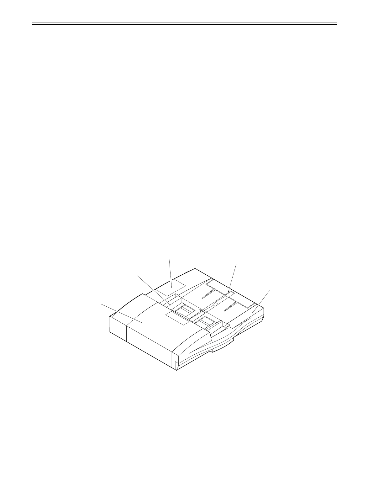
1.2 Names of Parts
1.2.1 External View
0011-1992
F-1-1
Book original supported (mobile hinge assembly; up/down)
Tracing paper mode no
Silent mode no
stamp no
Communication with host
machine
IP communication 2
Power supply 24 VDC, 13 VDC From printer unit by way of reader
unit.
Weight 21.5 kg (approx.) Not including delivery tray.
Dimensions 646 (W) x 569.5 (D) x 143 (H) mm Not including delivery tray.
Power consumption 100 W or less (during
operation)
Operating noise sound pressure: host machine + 3 dB Host machine + ADF + finisher
alone: 72 dB
sound quality: 10.78 sone (85 ipm)
DF opening/closing noise
(impact)
sound pressure: 70 dB
Operating noise same as host machine
Temperature range
Humidity range
[1] Upper cover [4] Manual feed tray
[2] Side guide [5] Front cover
[3] ADF controller cover
[1]
[2]
[3]
[4]
[5]
Chapter 1
1-3
1.2.2 Cross Section
0011-1993
F-1-2
1.3 Using the Machine
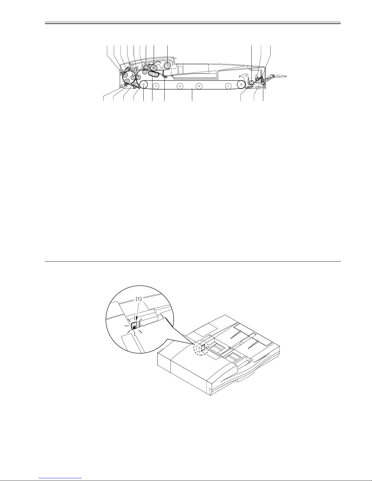
1.3.1 Original Set Indicator
0011-2222
The Original Set Indicator [1] goes on when an original is placed on the original tray, and flashes when a jam occurs.
F-1-3
-Warnings and Action to Take
If the Original Set indicator starts to flash while an original is inside the DADF, suspect a jam; go through the following to remove the jam:
1) Remove all originals from the original tray.
2) Open the upper cover, and remove the jam, if found.
3) Open the DADF, and remove the original from the copyboard glass, if found.
4) Put the originals back into initial sequence, and place the stack in the DADF.
[1] Reversing roller B member [13] Delivery roller B member
[2] Reversing roller B [14] Delivery roller
[3] Reversing flapper [15] Delivery guide flapper
[4] Registration pressure roller [16] Feeding belt
[5] Registration roller [17] Stopper plate
[6] Pull-off roller [18] Separation belt
[7] Pull-off pressure roller [19] Feed belt driver roller
[8] Feeding roller [20] Guide flapper
[9] Pickup roller [21] Pre-reversal flapper
[10] Manual feed registration roller [22] Reversing roller A
[11] Manual feed stopper plate [23] Reversing roller A member
[12] elivery roller A member
[1] [2] [3] [4] [5] [6] [7] [8] [9]
[10] [11] [12]
[15] [14] [13]
[16]
[18]
[17]
[19][20][21][23] [22]


Chapter 2 Functions


Contents
Contents
2.1 Basic Construction.........................................................................................................................................................2-1
2.1.1 Overview of Electrical Circuit ..................................................................................................................................................... 2-1
2.1.2 Inputs to ADF Controller PCB .................................................................................................................................................... 2-2
2.1.3 Outputs from ADF Controller PCB ............................................................................................................................................. 2-4
2.2 Basic Operation..............................................................................................................................................................2-4
2.2.1 Outline.......................................................................................................................................................................................... 2-4
2.2.2 Outline.......................................................................................................................................................................................... 2-6
2.2.3 CW Pickup/Delivery.................................................................................................................................................................... 2-7
2.2.4 Pre-Reversal/Reversal/Delivery................................................................................................................................................... 2-7
2.2.5 Manual Feeder Pickup/Delivery.................................................................................................................................................. 2-8
2.3 Document Detection ......................................................................................................................................................2-9
2.3.1 Outline.......................................................................................................................................................................................... 2-9
2.3.2 Detecting the Presence/Absence of an Original........................................................................................................................... 2-9
2.3.3 Original Size Detection 1........................................................................................................................................................... 2-10
2.3.4 Original Size Detection 2........................................................................................................................................................... 2-11
2.3.5 Detecting the Presence/Absence of an Original in the Manual Feeder...................................................................................... 2-14
2.4 Document Pickup/Separation.......................................................................................................................................2-15
2.4.1 Outline........................................................................................................................................................................................ 2-15
2.4.2 Moving Up/Down the Pickup Roller Unit................................................................................................................................. 2-15
2.4.3 Switching the Separation Pressure............................................................................................................................................. 2-17
2.4.4 Separation Sensor (S4) and Skew Sensor (S5) .......................................................................................................................... 2-18
2.4.5 Controlling the Pickup Motor (M3).............. .. ................................ ............................... .. .......................................................... 2-19
2.4.6 Controlling the Separation Motor (M4)..................................................................................................................................... 2-19
2.4.7 Sequence of Operations ............................................................................................................................................................. 2-20
2.5 Document Feeding/Delivery........................................................................................................................................2-20
2.5.1 Outline........................................................................................................................................................................................ 2-20
2.5.2 Controlling the Belt Motor (M2) ............................................................................................................................................... 2-21
2.5.3 Controlling the Delivery Motor (M5)............................... ............................... .......................................................................... 2-22
2.6 Feeding Unit.................................................................................................................................................................2-22
2.6.1 Outline of CW Pickup/Delivery................................................................................................................................................. 2-22
2.6.2 CW Pickup/Delivery Fixed Reading ......................................................................................................................................... 2-23
2.6.3 CW Pickup/Delivery (stream reading) ...................................................................................................................................... 2-27
2.6.4 Double-Sided Originals (fixed reading) .................................................................................................................................... 2-33
2.6.5 Fixed Reading (continuous; double-sided original)................................................................................................................... 2-39
2.6.6 Controlling the Reversal Motor (M1)............................................................................ ............................................................ 2-46
2.6.7 Manual Feeder Pickup/Delivery Operation............................................................................................................................... 2-46
2.7 Detecting Jams.............................................................................................................................................................2-47
2.7.1 Overview ................................................................................................................................................................................... 2-47
2.7.2 List of Jam Code ........................................................................................................................................................................ 2-48
2.7.3 Alarm Code................................................................................................................................................................................ 2-51
2.8 Power Supply...............................................................................................................................................................2-51
2.8.1 Overview.................................................................................................................................................................................... 2-51

Chapter 2
2-1
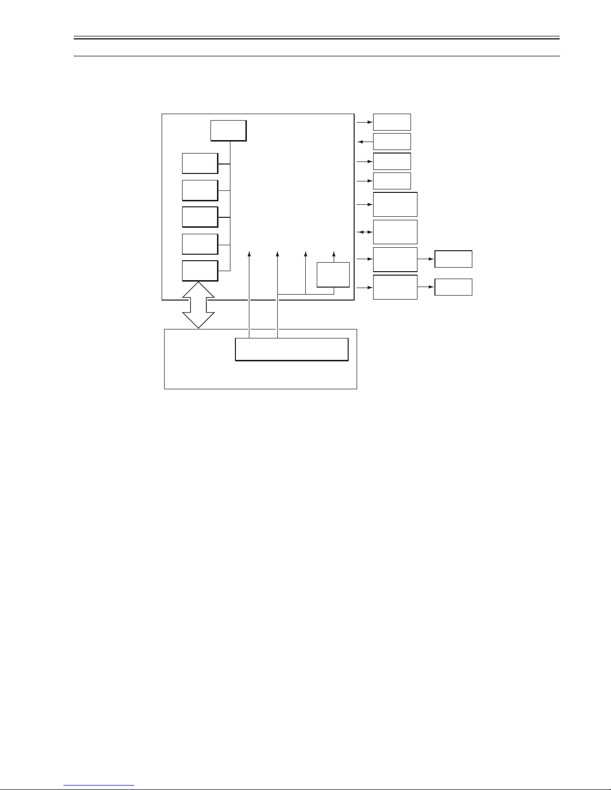
2.1 Basic Construction
2.1.1 Overview of Electrical Circuit
0011-2223
The machine's electrical mechanisms are controlled by the ADF controller PCB (microcomputer CPU). The CPU interprets signals from sensors and the host machine, and generates appropriate signals to drive such loads as motors and solenoids at such times as programmed in advance.
F-2-1
CPU
(Q1)
ROM
(IC1)
EEPROM
(IC2)
RAM
(Q4)
D/A
(Q9)
IPC
(Q2)
+5V +24V +5R+24R
Power supply PCB
Copier
Solenoid
Clutch
Original
indicator
LED PCB
Sub tray PCB
Reversal
motor
driver PCB
Belt motor
driver PCB
Motor
Sensor
Motor
Motor
ADF controller PCB
DC5V
(Q65)
Chapter 2
2-2
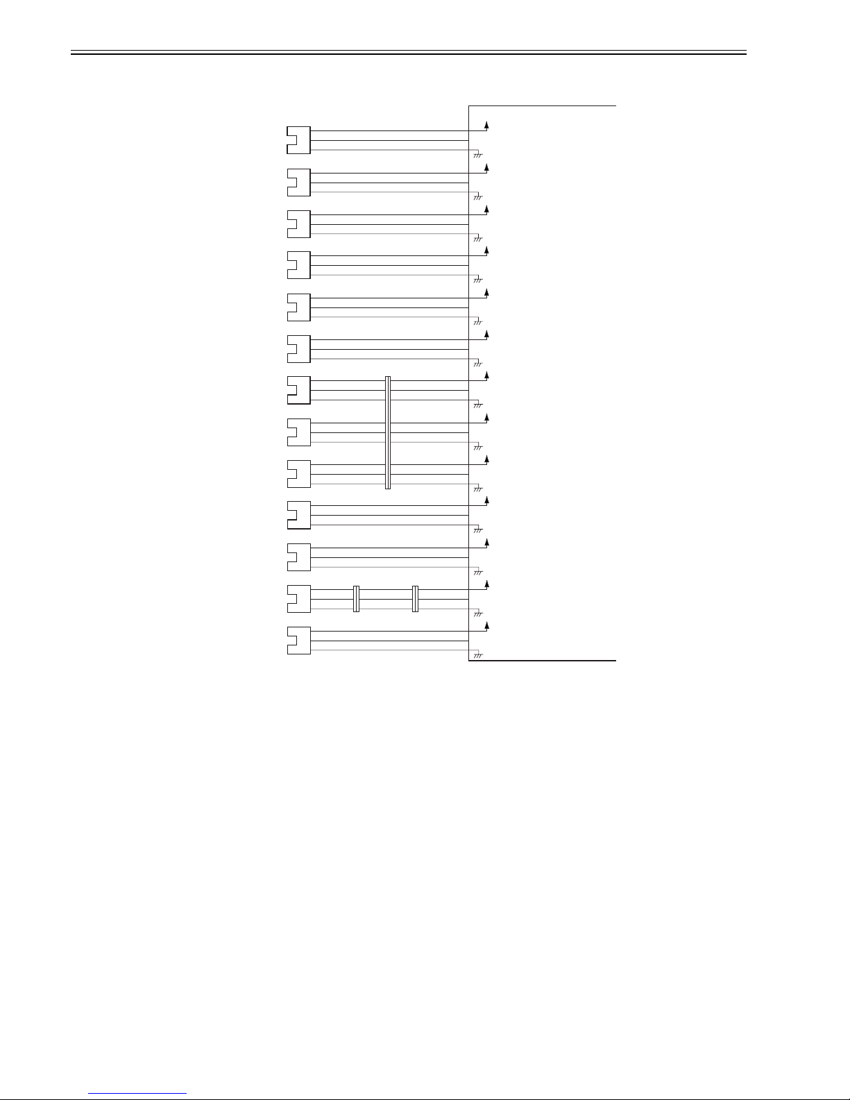
2.1.2 Inputs to ADF Controller PCB
0011-2225
-Inputs to ADF Controller PCB(1/2)
F-2-2
+5V
PI 1
BTCLK
J12-3
-2
-1
+5V
PI 2
SPCLK
J12-6
-5
-4
+5V
PI 3
LCVR
J12-7
-9
-8
+5V
PI 4
PRTR
J12-10
-12
-11
+5V
PI 5
TRCLK
J14-B10
-B9
-B8
+5V
PI 6
LCVF
J14-B5
-B7
-B6
+5V
PI 7
PKHP
J14-A3
-A5
-A4
-9
-7
-8
+5V
PI 8
PKH1
J14-A6
-A8
-A7
-6
-4
-5
+5V
PI 9
PKH2
J14-A9
-A11
-A10
-3
-1
-2
-1
-3
-2
-4
-6
-5
-7
-9
-8
+5V
PI 10
RFOP
J12-13
-15
-14
+5V
PI 11
EJCLK
J2-13
-15
-14
+5V
PI 12
MFST
J2-8
-10
-9
-5
-3
-4
-8
-10
-9
-3
-1
-2
-5
-7
-6
J141
J21J23
+5V
PI 13
EJJAM
J3-3
-2
-1
Pulses according to the
rotation speed of the belt
motor.
Pulses according to the
rotation speed of the
separation motor.
When the paper cover is
closed, '1'.
When paper is present,
'1'.
Pulses according to the
rotation speed of the
registration roller.
When the upper cover is
closed, '1'.
When the pickup roller is
in home position, '1'.
When the pickup roller is
on paper, '1'.
When the pickup roller is
on paper, '1'.
When the DADF is
closed, '1'.
Pulses according to the
rotation speed of the
delivery motor.
When paper is present,
'1'.
Belt motor clock
sensor
Separation motor
clock sensor
Upper cover sensor
(rear)
Pre-reversal sensor
Registration roller
clock sensor
Upper cover sensor
(front)
Pickup roller
home position
sensor
Pickup roller height
sensor 1
Pickup roller height
sensor 2
ADF open/closed
sensor
Delivery motor clock
sensor
Manual feed set
sensor
Original delivery
sensor
ADF controller PCB
When paper is present,
'1'.
Chapter 2
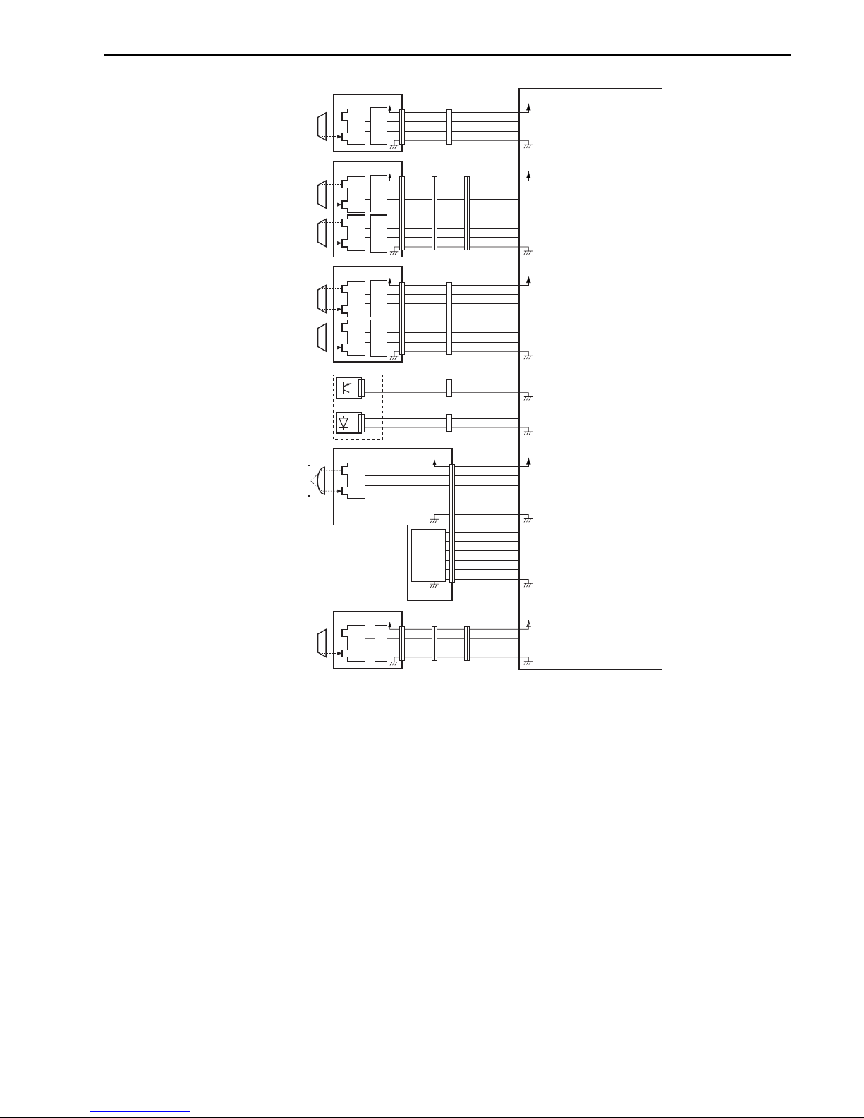
2-3
-Inputs to ADF Controller PCB(2/2)
F-2-3
+5V
+5V
TNSAJ
TNS
J14-B1
-B4
-B3
-B2
-4
-1
-2
-3
-2
-5
-4
-3
-4
-1
-2
-3
S1
+5V
+5V
RGBSAJ
RGBS
J13-8
-3
-4
S2
RGASAJ
RGAS
-5
-6
-7
-1
-6
-5
-4
-3
-2
-8
-3
-4
-5
-6
-7
-6
-1
-2
-3
-4
-5
-1
-6
-5
-4
-3
-2
-1
-6
-5
-4
-3
-2
S3
+5V
+5V
SPSAJ
SPS
J13-14
-9
-10
S4
SKSAJ
SKS
DTS
DTSAJ
TAILSAJ
TAILS
SSW-0
SSW-1
SSW-2
SSW-3
SSW-4
-11
-12
-13
J13-2
-1
-7-8-2
-1
-2
-1
-3-2-1
-2
-2
-1
-1
-6
-5
-4
-3
-2
-1
-6
-5
-4
-3
-2
-6
-1
-2
-3
-4
-5
S5
S6
+5V
+5V
MFRGSAJ
MFRGS
J2-4
-7
-6
-5
S9
+5V
+5V
S7
J14-A1
-A2
J5-12
-9
-10
-11
J5-6
-5
-4
-3
-2
-1
-2
-5
-4
-3
-8
-9
-10
-11
-12
-13
J144
J149
J131
J134
J132
J136
J140
J145
J133 J132J135
-9
-6
-7
-8
-4
-7
-6
-5
-1
-4
-3
-2
-7
-4
-5
-6
-4
-1
-2
-3
J23 J21J25
SW301
J51
Reference signal for
paper detection
When paper is present, '0'.
Paper
Reversal sensor
Pre-registration
roller paper sensor
Post registration
roller paper sensor
Separation sensor
Skew sensor
Original sensor
(light-receiving)
Original sensor
(light-emitting)
Original trailing
edge sensor
Manual feed
registration roller
paper sensor
ADF controller PCB
Reference signal for
paper detection
When paper is present, '0'.
Reference signal for
paper detection
When paper is present, '0'.
Reference signal for
paper detection
When paper is present, '0'.
Reference signal for
paper detection
When paper is present, '0'.
When paper is present, '0'.
Light intensity adjustment
signal
Light intensity adjustment
signal
When paper is present, '1'.
Light intensity adjustment
signal
When paper is present, '1'.
Signal according to
paper width
Reference signal for
paper detection
When paper is present, '0'.
Pickup tray
PCB
Original
width
detecting
switch
Comparator
circuit
Comparator
circuit
Comparator
circuit
Comparator
circuit
Comparator
circuit
Chapter 2
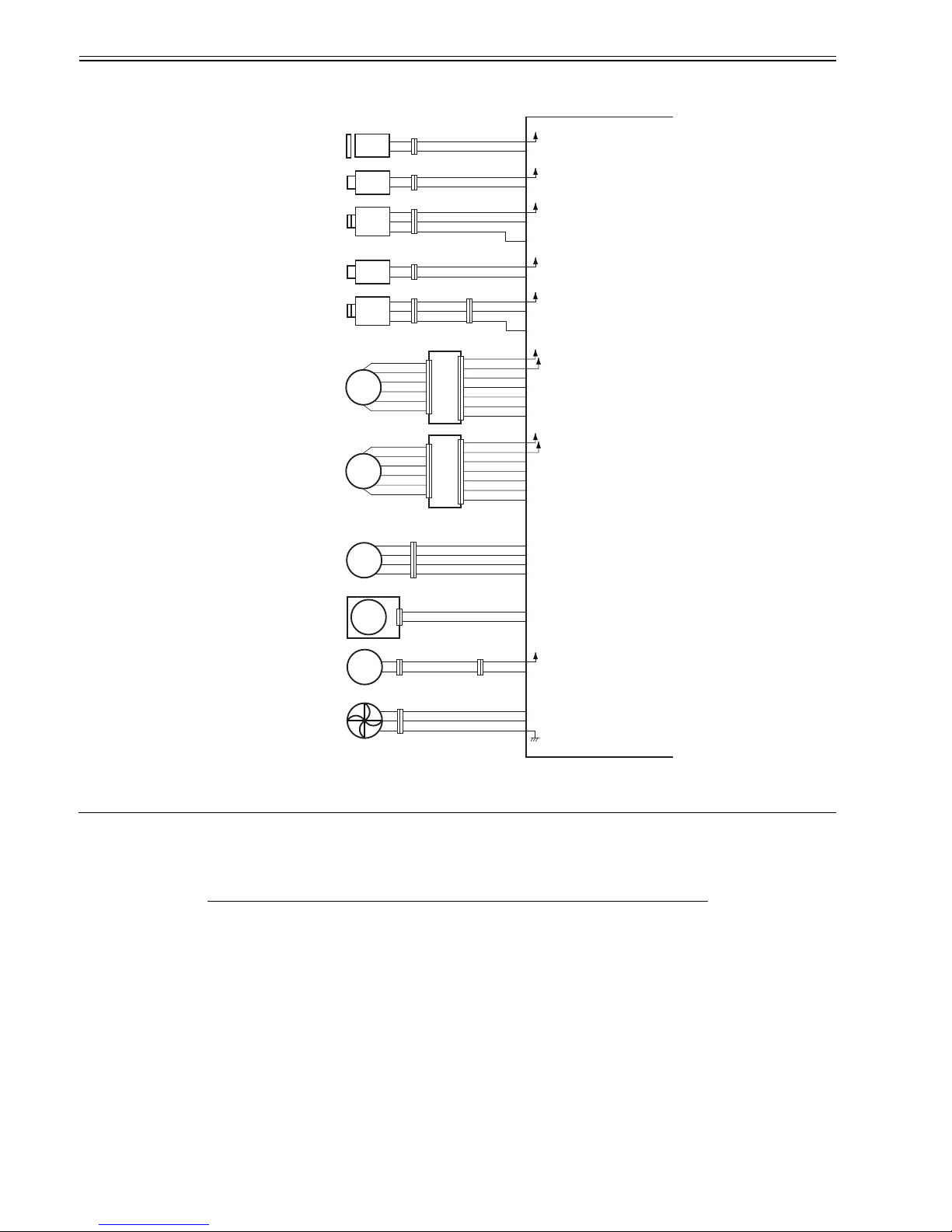
2-4
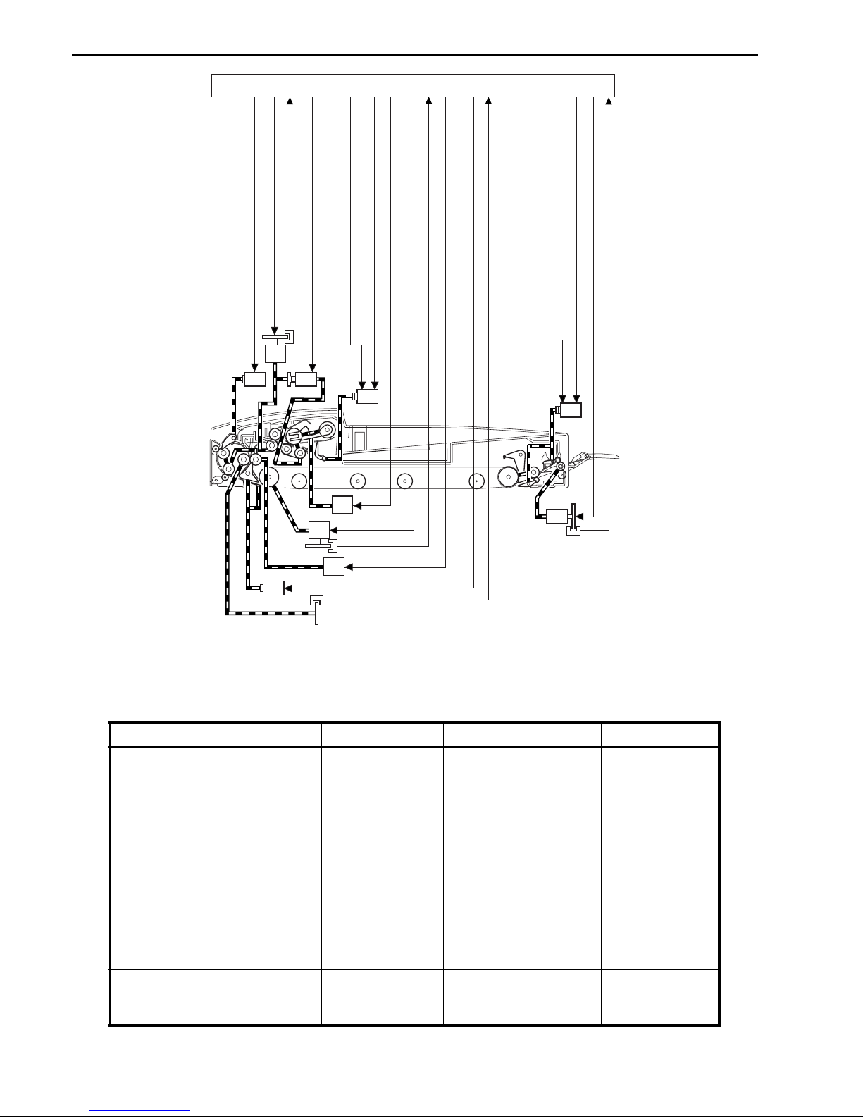
2.1.3 Outputs from ADF Controller PCB
0011-2226
-Outputs from ADF Controller PCB(1/1)
F-2-4
2.2 Basic Operation
2.2.1 Outline
0011-2227
The DADF uses five motors and one clutch to pick up, separate, move, and deliver originals.
Name (notation) Description
Reversal motor (M1) Moves and reverses originals.
Belt motor (M2) Moves originals.
Pickup motor (M3) Moves up/down the pickup roller.
Separation motor (M4) Separates originals.
Delivery motor (M5) Delivers originals and picks up manually fed originals.
Separation clutch (CL) Turns on/off the pull-off roller and the separation/feed drive system.
+24V
CLD*
J10-3
-4
+24V
SL1D*
J9-1
-2
+24V
SL2D1*
SL2D2*
J9-3
-4
-5
+24V
+24V
SL3D*
J10-1
-2
-2-1-1
-2
-2-1-1
-2
-2-1-1
-2
+24V
+24V
+5V
SL4D1*
SL4D2*
M1OB*
M1OA*
M1OB
M1OA
T-Vref
EJMD*
SEPM+
SEPM-
J2-1
-2
-3
-12
-11
-10
-1
-2
-3
-3
-2
-1
-1
-2
-3
-3
-2
-1
-1
-2
-3
J6-8~10
-1
-2
-3
-4
-5
-6
-4~6
-13
-12
-11
-10
-9
-8
-1
-2
-3
-4
-5
-6
+24V
+24V
A
A*
B
B*
-1
-2
-3
-4
-5
-6
+24V
+24V
A
A*
B
B*
-4~6
-13
-12
-11
-10
-9
-8
M1
J8-1
-2
-2
-1
J2-11
-12
-2
-1
-2-1-1
-2
-11
-12
M5
M4
J24
J81
J21
FM1
J601
J602
J21J22
J101
FAN(+24V)
LOCK
J9-6
-7
-8
-3
-2
-1
-1
-2
-3
J93
J92
J91
J102
CL
SL1
SL2
SL3
SL4
+24V
+5V
M2OB*
M2OA*
M2OB
M2OA
B-Vref
J7-8~10
-1
-2
-3
-4
-5
-6
M2
J71
J72
Separation clutch
Reversal solenoid
Stopper plate solenoid
(2-position)
Pre-reversal solenoid
Delivery solenoid
(2-position)
Reversal motor
Belt motor
Pickup motor
Separation motor
Delivery motor
ADF controller PCB
When '0',
the separation clutch
goes on.
When '0', the solenoid
goes on.
When '0', the solenoid
goes on. (position 1)
When '0', the solenoid
goes on. (position 2)
When '0', the solenoid
goes on.
When '0', the solenoid
goes on. (position 1)
When '0', the solenoid
goes on. (position 2)
For details,
see Functions.
For details,
see Functions.
For details,
see Functions.
For details,
see Functions.
For details,
see Functions.
When '1', the fan
goes on.
When the fan is
at rest, '1'.
Reversal moter
driver PCB
Belt motor
driver PCB
M3OA
M3OA*
M3OB
M3OB*
J11-1
-2
-3
-4
-1
-2
-3
-4
M3
J111
Chapter 2
2-5
Diagram of Drive
F-2-5
PI 2
PI 1
PI 5
PI 11
SL3
SL1
SL2
SL4
M5
Pre-reversal solenoid drive signal (SL1D)
Separation motor clock signal (SPCLK)
Separation motor drive signal
Separation clutch drive signal (CLD)
Stopper solenoid drive signal 2 (SL2D2)
Stopper plate solenoid signal 1 (SL2D1)
Pickup motor drive signal
Belt motor drive signal
Belt motor clock signal (BTCLK)
Reversal motor drive signal
Reversal solenoid drive signal (SL3D)
Registration roller clock signal (TRCLK)
Delivery solenoid drive signal 1 (SL4D)
Delivery motor drive signal
Delivery motor clock signal (EJCLK)
CL
Delivery solenoid drive signal 1 (SL4D)
ADF controller PCB
M2
M3
M4
M1
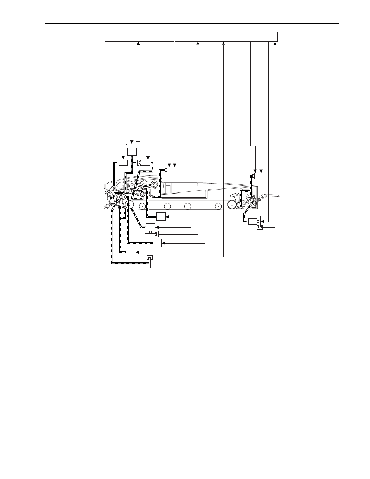
Chapter 2
2-6
Sensor Arrangement
F-2-6
2.2.2 Outline
0011-2233
The DADF operates in either of the following three modes; the DADF operates in response to instructions from the copier, executing appropriate modes to suit the
copier's operations.
The following table shows each operation mode, an outline of its operation, and its corresponding copying mode:
T-2-1
No. Mode Operation Copying mode Copying operation
1 CW pickup/delivery Picks up an original, and
delivers it as it is after
copying.
Single-sided original to
single-sided copy
Signal-sided original to
double-sided copy
Stream reading (fixed if
the reproduction ratio is
not between 50% and
200%)
2 Pre-reversal pickup/reversal/ delivery Reverses an original,
picks it up, reverses it
once again after copying,
and delivers it.
Fixed reading
Double-sided original
to double-sided copy
Double-sided original
to single-sided copy
Fixed reading
3 Manual feeder
pickup/delivery
Picks up an original from
the manual feeder, and
delivers it after copying.
Manual copy Fixed reading
PI 2
PI 1
PI 5
PI 11
SL3
SL1
SL2
SL4
M5
Pre-reversal solenoid drive signal (SL1D)
Separation motor clock signal (SPCLK)
Separation motor drive signal
Separation clutch drive signal (CLD)
Stopper solenoid drive signal 2 (SL2D2)
Stopper plate solenoid signal 1 (SL2D1)
Pickup motor drive signal
Belt motor drive signal
Belt motor clock signal (BTCLK)
Reversal motor drive signal
Reversal solenoid drive signal (SL3D)
Registration roller clock signal (TRCLK)
Delivery solenoid drive signal 1 (SL4D)
Delivery motor drive signal
Delivery motor clock signal (EJCLK)
CL
Delivery solenoid drive signal 1 (SL4D)
ADF controller PCB
M2
M3
M4
M1
Chapter 2
2-7
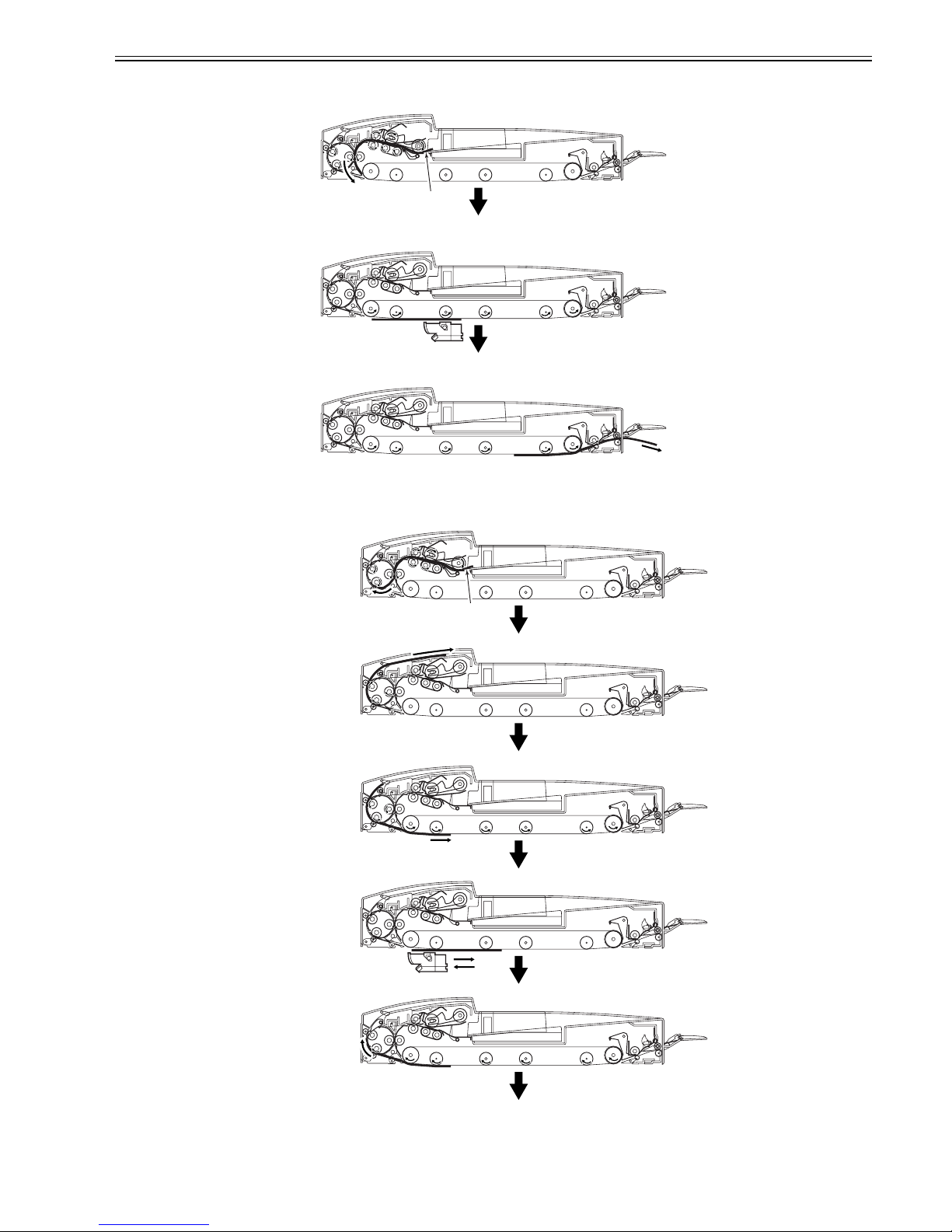
2.2.3 CW Pickup/Delivery
0011-2234
The following is an outline of the flow of originals.
Pickup
F-2-7
Scan
F-2-8
Delivery
F-2-9
2.2.4 Pre-Reversal/Reversal/Delivery
0011-2235
The following is an outline of the flow of originals:
F-2-10
Picking up
Pre-reversing
Feeding
Copying
the 1st side
Moving
To next page
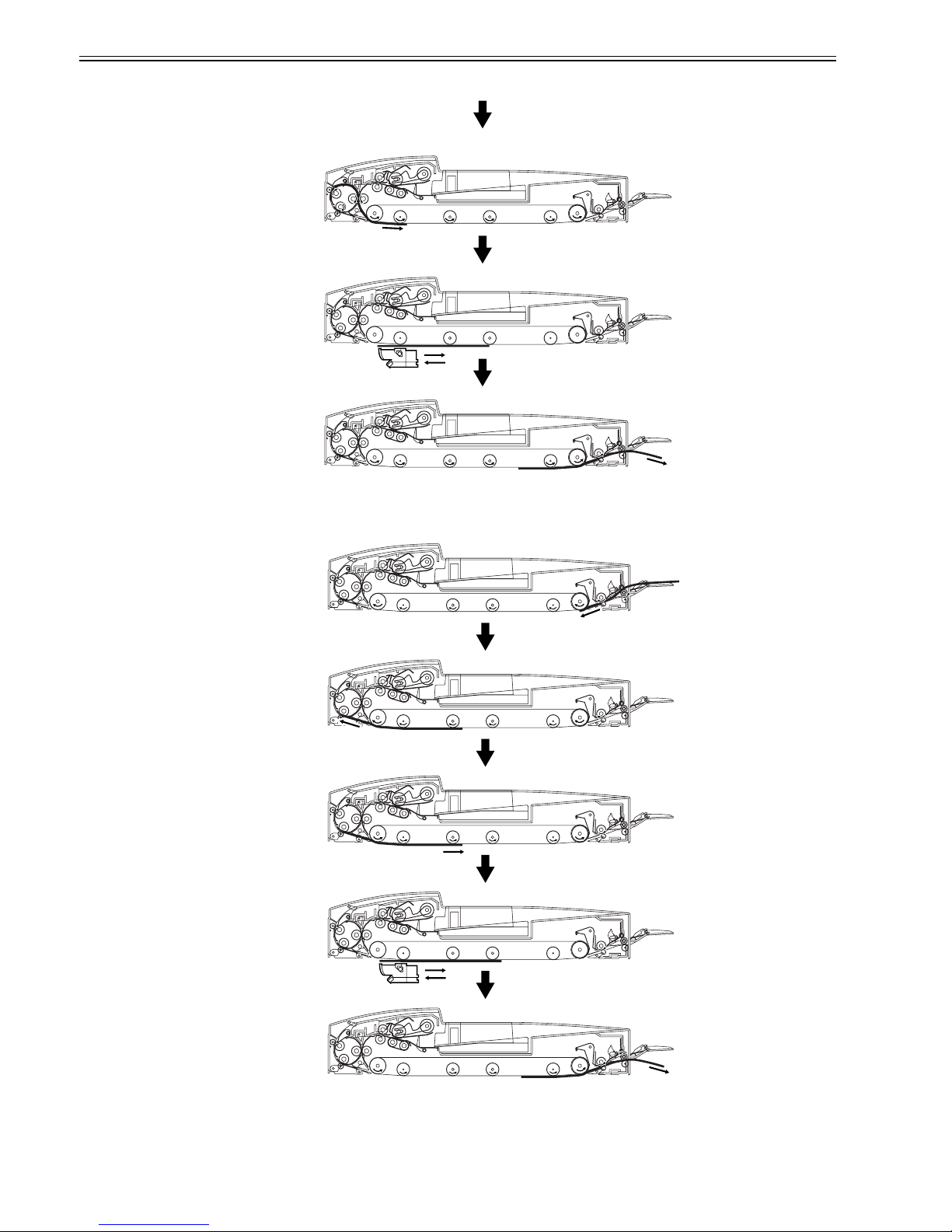
Chapter 2
2-8
F-2-11
2.2.5 Manual Feeder Pickup/Delivery
0011-2237
The following is an outline of the flow of originals:
F-2-12
Reversing
Copying
the 2nd side
Delivering
From previous page
Picking up
Stopping
Switching back
Copying
Delivering
 Loading...