

Canon DADF-N1 Service Manual
SERVICE
MANUAL
imageRUNNER
iR2270/2870/
3570/4570
DADF-N1
COPYRIGHT 2004 CANON INC. CANON imageRUNNER DADF-N1 REV. 0 PRINTED IN U.S.A.
DU7-1128-000
SEPT. 2004
REV. 0

Application
This manual has been issued by Canon Inc. for qualified persons to learn technical theory, installation,
maintenance, and repair of products. This manual covers all localities where the products are sold. For
this reason, there may be information in this manual that does not apply to your locality.
Corrections
This manual may contain technical inaccuracies or typographical errors due to improvements or changes
in products. When changes occur in applicable products or in the contents of this manual, Canon will
release technical information as the need arises. In the event of major changes in the contents of this
manual over a long or short period, Canon will issue a new edition of this manual.
The following paragraph does not apply to any countries where such provisions are inconsistent with
local law.
Trademarks
The product names and company names used in this manual are the registered trademarks of the
individual companies.
Copyright
This manual is copyrighted with all rights reserved. Under the copyright laws, this manual may not be
copied, reproduced or translated into another language, in whole or in part, without the written consent
of Canon Inc.
COPYRIGHT © 2001 CANON INC.
Printed in Japan
Caution
Use of this manual should be strictly supervised to avoid disclosure of confidential information.

Introduction
Symbols Used
This documentation uses the following symbols to indicate special information:
Symbol Description
Indicates an item of a non-specific nature, possibly classified as Note,
Caution, or Warning.
Indicates an item requiring care to avoid electric shocks.
Indicates an item requiring care to avoid combustion (fire).
Indicates an item prohibiting disassembly to avoid electric shocks or
problems.
Indicates an item requiring disconnection of the power plug from the electric
outlet.
Memo
REF.
Indicates an item intended to provide notes assisting the understanding of the
topic in question.
Indicates an item of reference assisting the understanding of the topic in
question.
Provides a description of a service mode.
Provides a description of the nature of an error indication.

Introduction
The following rules apply throughout this Service Manual:
1. Each chapter contains sections explaining the purpose of specific functions and the
relationship between electrical and mechanical systems with reference to the timing of
operation.
In the diagrams, represents the path of mechanical drive; where a signal name
accompanies the symbol, the arrow indicates the direction of the electric
signal.
The expression "turn on the power" means flipping on the power switch, closing the front
door, and closing the delivery unit door, which results in supplying the machine with
power.
2. In the digital circuits, '1'is used to indicate that the voltage level of a given signal is
"High", while '0' is used to indicate "Low".(The voltage value, however, differs from
circuit to circuit.) In addition, the asterisk (*) as in "DRMD*" indicates that the DRMD
signal goes on when '0'.
In practically all cases, the internal mechanisms of a microprocessor cannot be checked
in the field. Therefore, the operations of the microprocessors used in the machines are
not discussed: they are explained in terms of from sensors to the input of the DC
controller PCB and from the output of the DC controller PCB to the loads.
The descriptions in this Service Manual are subject to change without notice for product
improvement or other purposes, and major changes will be communicated in the form of
Service Information bulletins.
All service persons are expected to have a good understanding of the contents of this
Service Manual and all relevant Service Information bulletins and be able to identify and
isolate faults in the machine."

Contents
Contents
Chapter 1 Specifications
1.1 Product Specifications ............................................................................................... 1-1
1.1.1 Specifications ...................................................................................................... 1-1
1.2 Names of Parts ........................................................................................................... 1-4
1.2.1 External View ..................................................................................................... 1-4
1.2.2 Cross Section....................................................................................................... 1-5
1.3 Using the Machine ..................................................................................................... 1-6
1.3.1 Original Placement Indicator .............................................................................. 1-6
1.3.2 Warning and Action to Take............................................................................... 1-6
Chapter 2 Functions
2.1 Basic Construction ..................................................................................................... 2-1
2.1.1 Outline of the Electrical Circuitry....................................................................... 2-1
2.1.2 Inputs to the ADF Controller PCB...................................................................... 2-2
2.1.3 Output for the ADF Controller PCB ................................................................... 2-3
2.2 Basic Operation.......................................................................................................... 2-4
2.2.1 Transmission of Drive......................................................................................... 2-4
2.2.2 Outline of the Operation Mode ........................................................................... 2-6
2.2.3 Normal Rotation Pickup/Delivery (single-sided original -> single-sided print) 2-6
2.2.4 Normal Rotation Pickup/Reversal Delivery (double-sided original -> doubles-sided
print) ......................................................................................................................... 2-8
2.2.5 Idle Feed/Pickup/Delivery (double-sided originals of mixed sizes -> double-sided
print) ....................................................................................................................... 2-10
2.2.6 Idle Feeding/Reversal Pickup/Delivery (single-sided originals of mixed sizes ->
single-sided prints) ................................................................................................. 2-13
2.3 Document Detection ................................................................................................ 2-16
2.3.1 Outline............................................................................................................... 2-16
2.3.2 Detecting the Presence/Absence of an Original................................................ 2-17
2.3.3 Detecting the Last Original ............................................................................... 2-18
2.3.4 Original Size Initial Identification (feed direction)........................................... 2-19
2.3.5 Original Size Initial Identification (cross-feed direction) ................................. 2-20
2.3.6 Slide Guide Positioning Spacer......................................................................... 2-23

Contents
2.3.7 Original Size Final Identification...................................................................... 2-24
2.4 Document Pickup/Separation................................................................................... 2-27
2.4.1 Basic Operation ................................................................................................. 2-27
2.4.2 Pickup Roller and the Stopper........................................................................... 2-30
2.4.3 Timing of Pickup .............................................................................................. 2-32
2.4.4 Controlling the Pickup Motor (M2) .................................................................. 2-32
2.5 Document Reversing................................................................................................ 2-34
2.5.1 Basic Operation ................................................................................................. 2-34
2.5.2 Sequence of Operation ...................................................................................... 2-36
2.6 Document Feeding/Delivery .................................................................................... 2-37
2.6.1 Basic Operation ................................................................................................. 2-37
2.6.2 Sequence of Operation ...................................................................................... 2-38
2.6.3 Controlling the Feed Motor (M1) ..................................................................... 2-38
2.7 Detecting Jams ......................................................................................................... 2-40
2.7.1 Jams................................................................................................................... 2-40
2.8 Power Supply ........................................................................................................... 2-42
2.8.1 Power Supply .................................................................................................... 2-42
2.9 Stamp Operation ...................................................................................................... 2-43
2.9.1 Outline............................................................................................................... 2-43
Chapter 3 Parts Replacement Procedure
3.1 Removing from the Host Machine ............................................................................. 3-1
3.1.1 Feeder .................................................................................................................. 3-1
3.1.1.1 Disconnecting from the Host Machine......................................................... 3-1
3.2 External Covers.......................................................................................................... 3-2
3.2.1 Front Cover .........................................................................................................3-2
3.2.1.1 Removing the Front Cover ........................................................................... 3-2
3.2.2 Rear Cover .......................................................................................................... 3-2
3.2.2.1 Removing the Rear Cover ............................................................................ 3-2
3.2.3 Feeder Cover ....................................................................................................... 3-3
3.2.3.1 Removing the Feeder Cover ......................................................................... 3-3
3.3 Drive System.............................................................................................................. 3-4
3.3.1 Pickup Motor ....................................................................................................... 3-4
3.3.1.1 Removing the Rear Cover ............................................................................ 3-4
3.3.1.2 Removing the Pickup Motor ........................................................................ 3-4
3.3.1.3 Mounting the Pickup Motor ......................................................................... 3-5
3.3.2 Feed Motor ..........................................................................................................3-5
3.3.2.1 Removing the Rear Cover ............................................................................ 3-5

Contents
3.3.2.2 Removing the Feed Motor............................................................................ 3-6
3.3.2.3 Mounting the Feed Motor ............................................................................ 3-6
3.3.3 Timing Belt/Pulley .............................................................................................. 3-7
3.3.3.1 Removing the Rear Cover ............................................................................ 3-7
3.3.3.2 Removing the Front Cover ........................................................................... 3-8
3.3.3.3 Removing the Feeder Cover......................................................................... 3-8
3.3.3.4 Removing the Pickup Motor ........................................................................ 3-9
3.3.3.5 Removing the Pickup Clutch........................................................................ 3-9
3.3.3.6 Removing the Reinforcing Plate ................................................................ 3-10
3.3.3.7 Removing the Feed Motor.......................................................................... 3-10
3.3.3.8 Detaching the Timing Belt and the Pulley ................................................. 3-11
3.3.4 Pickup Clutch .................................................................................................... 3-13
3.3.4.1 Removing the Rear Cover .......................................................................... 3-13
3.3.4.2 Removing the Pickup Motor ...................................................................... 3-13
3.3.4.3 Removing the Pickup Clutch...................................................................... 3-14
3.3.4.4 Mounting the Pickup Clutch ...................................................................... 3-15
3.4 Document Feeding System ...................................................................................... 3-16
3.4.1 Pickup Roller Unit ............................................................................................ 3-16
3.4.1.1 Removing the Front Cover ......................................................................... 3-16
3.4.1.2 Removing the Feeder Cover....................................................................... 3-16
3.4.1.3 Removing the Pickup Roller Unit.............................................................. 3-16
3.4.1.4 Mounting the Pickup Roller Unit ............................................................... 3-17
3.4.2 Pickup Roller/Separation Roller ....................................................................... 3-18
3.4.2.1 Removing the Front Cover ......................................................................... 3-18
3.4.2.2 Removing the Feeder Cover....................................................................... 3-18
3.4.2.3 Removing the Pickup Roller Unit.............................................................. 3-18
3.4.2.4 Removing the Pickup Roller and the Separation Roller ............................ 3-19
3.4.3 Separation Plate/Separation Pad ....................................................................... 3-19
3.4.3.1 Removing the Separation Plate and the Separation Pad ............................ 3-19
3.4.3.2 Adjusting the Separation Pressure.............................................................. 3-20
3.4.4 Upper Registration Roller ................................................................................. 3-21
3.4.4.1 Removing the Front Cover ......................................................................... 3-21
3.4.4.2 Removing the Feeder Cover....................................................................... 3-21
3.4.4.3 Removing the Upper Registration Roller................................................... 3-21
3.4.5 Lower Registration Roller ................................................................................. 3-22
3.4.5.1 Removing the Rear Cover .......................................................................... 3-22
3.4.5.2 Removing the Front Cover ......................................................................... 3-22
3.4.5.3 Removing the Feeder Cover....................................................................... 3-23
3.4.5.4 Removing the Pickup Motor ...................................................................... 3-23
3.4.5.5 Removing the Pickup Clutch...................................................................... 3-24

Contents
3.4.5.6 Removing the Reinforcing Plate ................................................................ 3-24
3.4.5.7 Removing the Feed Motor.......................................................................... 3-25
3.4.5.8 Detaching the Timing Belt and the Pulley ................................................. 3-25
3.4.5.9 Removing the Feeder Unit ......................................................................... 3-27
3.4.5.10 Removing the Upper Delivery Reversing Roller ..................................... 3-28
3.4.5.11 Removing the Platen Guide L .................................................................. 3-29
3.4.5.12 Removing the Read Roller 1 .................................................................... 3-29
3.4.5.13 Removing the Read Roller 2 .................................................................... 3-31
3.4.5.14 Removing the Lower Registration Roller ................................................ 3-31
3.4.6 Delivery Reversing Roller (upper) .................................................................... 3-32
3.4.6.1 Removing the Rear Cover .......................................................................... 3-32
3.4.6.2 Removing the Front Cover ......................................................................... 3-33
3.4.6.3 Removing the Feeder Cover ....................................................................... 3-33
3.4.6.4 Removing the Pickup Motor ...................................................................... 3-34
3.4.6.5 Removing the Pickup Clutch...................................................................... 3-34
3.4.6.6 Removing the Reinforcing Plate ................................................................ 3-35
3.4.6.7 Removing the Feed Motor.......................................................................... 3-35
3.4.6.8 Detaching the Timing Belt and the Pulley ................................................. 3-36
3.4.6.9 Removing the Feeder Unit ......................................................................... 3-38
3.4.6.10 Removing the Upper Delivery Reversing Roller ..................................... 3-39
3.4.7 Read Roller 1 .....................................................................................................3-39
3.4.7.1 Removing the Rear Cover .......................................................................... 3-39
3.4.7.2 Removing the Front Cover ......................................................................... 3-40
3.4.7.3 Removing the Feeder Cover ....................................................................... 3-40
3.4.7.4 Removing the Pickup Motor ...................................................................... 3-40
3.4.7.5 Removing the Pickup Clutch...................................................................... 3-41
3.4.7.6 Removing the Reinforcing Plate ................................................................ 3-42
3.4.7.7 Removing the Feed Motor.......................................................................... 3-42
3.4.7.8 Detaching the Timing Belt and the Pulley ................................................. 3-43
3.4.7.9 Removing the Feeder Unit ......................................................................... 3-45
3.4.7.10 Removing the Platen Guide L .................................................................. 3-45
3.4.7.11 Removing the Read Roller 1 .................................................................... 3-46
3.4.8 Read Roller 2 .....................................................................................................3-47
3.4.8.1 Removing the Rear Cover .......................................................................... 3-47
3.4.8.2 Removing the Front Cover ......................................................................... 3-48
3.4.8.3 Removing the Feeder Cover ....................................................................... 3-48
3.4.8.4 Removing the Pickup Motor ...................................................................... 3-49
3.4.8.5 Removing the Pickup Clutch...................................................................... 3-49
3.4.8.6 Removing the Reinforcing Plate ................................................................ 3-50
3.4.8.7 Removing the Feed Motor.......................................................................... 3-50

Contents
3.4.8.8 Detaching the Timing Belt and the Pulley ................................................. 3-51
3.4.8.9 Removing the Feeder Unit ......................................................................... 3-53
3.4.8.10 Removing the Read Roller 2 .................................................................... 3-54
3.4.9 Platen Roller ...................................................................................................... 3-54
3.4.9.1 Removing the Rear Cover .......................................................................... 3-54
3.4.9.2 Removing the Front Cover ......................................................................... 3-55
3.4.9.3 Removing the Feeder Cover....................................................................... 3-55
3.4.9.4 Removing the Pickup Motor ...................................................................... 3-56
3.4.9.5 Removing the Pickup Clutch...................................................................... 3-56
3.4.9.6 Removing the Reinforcing Plate ................................................................ 3-57
3.4.9.7 Removing the Feed Motor.......................................................................... 3-57
3.4.9.8 Detaching the Timing Belt and the Pulley ................................................. 3-58
3.4.9.9 Removing the Feeder Unit ......................................................................... 3-60
3.4.9.10 Removing the Platen Guide L .................................................................. 3-61
3.4.9.11 Removing the Platen Roller ..................................................................... 3-61
3.4.10 Delivery Reversing Roller (lower) .................................................................. 3-62
3.4.10.1 Removing the Lower Delivery Reversing Roller..................................... 3-62
3.4.10.2 Removing the Rear Cover ........................................................................ 3-62
3.4.10.3 Removing the Front Cover ....................................................................... 3-63
3.4.10.4 Removing the Feeder Cover..................................................................... 3-63
3.4.10.5 Removing the Pickup Motor .................................................................... 3-64
3.4.10.6 Removing the Pickup Clutch.................................................................... 3-64
3.4.10.7 Removing the Reinforcing Plate .............................................................. 3-65
3.4.10.8 Removing the Feed Motor........................................................................ 3-65
3.4.10.9 Detaching the Timing Belt and the Pulley ............................................... 3-66
3.4.10.10 Removing the Feeder Unit ..................................................................... 3-68
3.4.10.11 Removing the Lower Delivery Reversing Roller Unit........................... 3-69
3.4.11 Read Roller Roll .............................................................................................. 3-69
3.4.11.1 Removing the Read Roller 2 Roll ............................................................ 3-69
3.4.12 Separation Guide Sheet ................................................................................... 3-70
3.4.12.1 Before Replacing the Separation Guide Sheet ......................................... 3-70
3.4.12.2 Removing the Front Cover ....................................................................... 3-70
3.4.12.3 Removing the Feeder Cover..................................................................... 3-70
3.4.12.4 Replacing the Separation guide Sheet...................................................... 3-71
3.4.13 Feed Roller Guide ........................................................................................... 3-71
3.4.13.1 Repacking the Feed Roll Guide (dust-collecting tape) ............................ 3-71
3.5 Electrical System ..................................................................................................... 3-73
3.5.1 ADF Controller PCB ......................................................................................... 3-73
3.5.1.1 Removing the Rear Cover .......................................................................... 3-73
3.5.1.2 Removing the ADF Controller PCB .......................................................... 3-73

Contents
3.5.2 Inner Sensor of Feed Unit .................................................................................3-74
3.5.2.1 Removing the Rear Cover .......................................................................... 3-74
3.5.2.2 Removing the Front Cover ......................................................................... 3-74
3.5.2.3 Removing the Feeder Cover ....................................................................... 3-75
3.5.2.4 Removing the Pickup Motor ...................................................................... 3-75
3.5.2.5 Removing the Pickup Clutch...................................................................... 3-75
3.5.2.6 Removing the Reinforcing Plate ................................................................ 3-76
3.5.2.7 Removing the Feed Motor.......................................................................... 3-76
3.5.2.8 Detaching the Timing Belt and the Pulley ................................................. 3-77
3.5.2.9 Removing the Feeder Unit ......................................................................... 3-79
3.5.2.10 Removing the Upper Delivery Reversing Roller ..................................... 3-80
3.5.2.11 Removing the Platen Guide L .................................................................. 3-80
3.5.2.12 Removing the Read Roller 1 .................................................................... 3-81
3.5.2.13 Removing the Read Roller 2 .................................................................... 3-82
3.5.2.14 Removing the Platen Roller ..................................................................... 3-83
3.5.2.15 Removing the Feeder Unit Inside Sensor................................................. 3-84
3.5.3 Document Width Volume .................................................................................3-85
3.5.3.1 Removing the Front Cover ......................................................................... 3-85
3.5.3.2 Removing the Original Width Volume ...................................................... 3-85
3.5.3.3 Mounting the Original Width Volume ....................................................... 3-86
3.5.4 Cover Open/Closed Sensor ...............................................................................3-86
3.5.4.1 Removing the Rear Cover .......................................................................... 3-86
3.5.4.2 Removing the Cover Open/Closed Sensor ................................................. 3-87
3.5.5 Document Set Sensor ........................................................................................3-87
3.5.5.1 Removing the Rear Cover .......................................................................... 3-87
3.5.5.2 Removing the Original Placement Sensor.................................................. 3-88
3.5.6 Pressurization Solenoid .....................................................................................3-88
3.5.6.1 Removing the Rear Cover .......................................................................... 3-88
3.5.6.2 Removing the ADF Controller PCB .......................................................... 3-89
3.5.6.3 Removing the Locking Solenoid ................................................................ 3-89
Chapter 4 Maintenance
4.1 User Maintenance ...................................................................................................... 4-1
4.1.1 Cleaning .............................................................................................................. 4-1
4.1.2 Replacement ........................................................................................................ 4-2
4.2 Maintenance and Inspection ...................................................................................... 4-4
4.2.1 Periodically Replaced Parts ................................................................................. 4-4
4.2.1.1 Periodically Replaced Parts.......................................................................... 4-4

Contents
4.2.2 Durables .............................................................................................................. 4-4
4.2.2.1 Durables ....................................................................................................... 4-4
4.2.3 Periodical Servicing ............................................................................................ 4-5
4.2.3.1 Scheduled Servicing ..................................................................................... 4-5
4.2.4 Cleaning .............................................................................................................. 4-8
4.2.4.1 ADF Components......................................................................................... 4-8
4.2.4.2 Rollers and Guides ....................................................................................... 4-8
4.2.4.3 Applying Silicone Oil to the Reading Glass (copyboard glass)................. 4-12
4.3 Adjustment............................................................................................................... 4-14
4.3.1 Basic Adjustment .............................................................................................. 4-14
4.3.1.1 Overview .................................................................................................... 4-14
4.3.1.2 Adjusting the Tray Width........................................................................... 4-14
4.3.1.3 Adjusting the Height .................................................................................. 4-15
4.3.1.4 Adjusting the Right Angles ........................................................................ 4-17
4.3.1.5 Adjusting the Read Position ....................................................................... 4-19
4.3.1.6 Adjusting the Magnification....................................................................... 4-19
4.3.1.7 Adjusting the Horizontal Registration........................................................ 4-19
4.3.1.8 Adjusting the Trailing Edge Registration................................................... 4-20
4.3.1.9 Adjusting the White Level ......................................................................... 4-20
4.3.2 Adjustment at Time of Parts Replacement ....................................................... 4-21
4.3.2.1 Adjusting the Side Guide Plate .................................................................. 4-21
4.4 Outline of Electrical Components............................................................................ 4-22
4.4.1 Motors, Clutches, Solenoids, PCBs, and Others............................................... 4-22
4.5 Variable Resistors (VR), Light-Emitting Diodes (LED), and Check Pins by PCB. 4-25
4.5.1 Overview ........................................................................................................... 4-25
4.5.2 ADF Controller PCB......................................................................................... 4-25
4.5.3 Relay PCB......................................................................................................... 4-26
4.5.4 Original Placement LED PCB .......................................................................... 4-26
Chapter 5 Error Code
5.1 Overview.................................................................................................................... 5-1
5.1.1 Overview ............................................................................................................. 5-1
5.2 User Error Code ......................................................................................................... 5-2
5.2.1 Alarm Code List.................................................................................................. 5-2
5.3 Service Error Code..................................................................................................... 5-3
5.3.1 Error Code List.................................................................................................... 5-3
5.4 Jam Codes .................................................................................................................. 5-4
5.4.1 Jam Code List...................................................................................................... 5-4

Chapter 1
Specifications

Contents
Contents
1.1 Product Specifications................................................................................1-1
1.1.1 Specifications ...................................................................................... 1-1
1.2 Names of Parts ...........................................................................................1-4
1.2.1 External View......................................................................................1-4
1.2.2 Cross Section.......................................................................................1-5
1.3 Using the Machine .....................................................................................1-6
1.3.1 Original Placement Indicator ..............................................................1-6
1.3.2 Warning and Action to Take...............................................................1-6

1.1 Product Specifications
Chapter 1
1.1.1 Specifications
T-1-1
Item Description
Method of original pickup auto pickup/delivery
Placement of original face-up
Point of original reference center
Method of original
separation
Type of original
Original size
top separation
single-sided sheet if longer than
AB-configuration: 42 to 128 g/m2
Inch-configuration: 50 to 128 g/m2
double-sided sheet: 50 to 128g/m2
AB-configuration: B6/A5/A5R/B5/
B5R
A4/A4R/B4/A3
Inch-configuration: STMT/LTR/
LTRR/LGL/11"X17"
original width: 148 to 297 mm
0006-2222
Remarks
432 mm,
single-sided,
single feed
60 to 90 g/m2
if STMT/B6,
horizontal feed
only
original length (feed direction): 128 to
432 (630) mm
if in parentheses,
in reference to
operator
1-1

Chapter 1
Item Description
50 sheets (of 80 g/m2 pap
er)
if in excess of 80 g/m2, conversion
Original tray capacity
applies
if folded, 10 mm or less
if 42 g/m2, 10 sheets
Method of reading stream reading
Original processing mode single-sided original processing, double-
sided original processing
Identification of original
by photointerrupter in pickup tray
size
Jam recovery offered
DONE stamp offered
offered, of same configuration
offered, of different configurations
Remarks
in lengthwise
direction, 2 pc.;
in breadthwise
direction, 1 pc. +
volume
Original size mix
combination of different configurations
AB-configuration: A3/B4 A4/B5/B4/
A4R B5/A5 A5/B6
Book original supported (must be 50 mm or less in
thickness)
Speed of original feed 236 mm/sec (at 100%)
Speed of original
45 ipm (single-sided) Speed may be
processing (A4/LTR)
19 ipm (double-sided)
1-2
weight
guaranteed as in
the case of
duplexing
varied.

Chapter 1
Item Description
Communication with host
serial
machine
Power supply 24 VDC (power)
13 VDC (logic)
Weight 8.5 kg (approx.)
Dimensions 565 (W) x 538 (D) x 122 (H) mm
A-configuration KCDxxxxx
Inch/A-configuration
KCCxxxx
Serial number
Operating
environment
temperature
range
humidity
range
AB-configuration
Inch/AB-configuration
in keeping with host machine
in keeping with host machine
KCBxxxxx
KCExxxxx
Remarks
Supplied by host
machine.
1-3
Chapter 1
[
[4]
6]
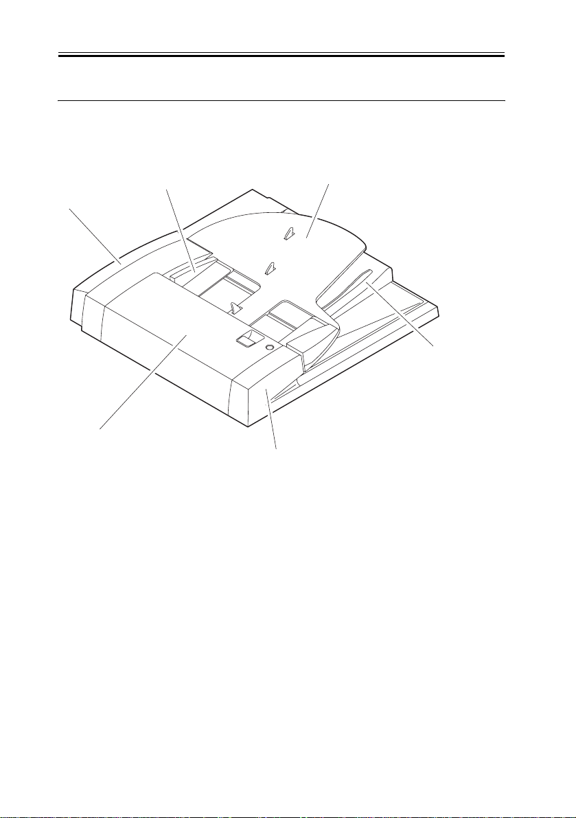
1.2 Names of Parts
1.2.1 External View
[3]
2]
[1]
F-1-1
[5]
T-1-2
0006-2225
[
[1] Feeder cover [4] Original pickup tray
[2] Rear cover [5] Front cover
[3] Slide guide [6] Original delivery
assembly
1-4
Chapter 1
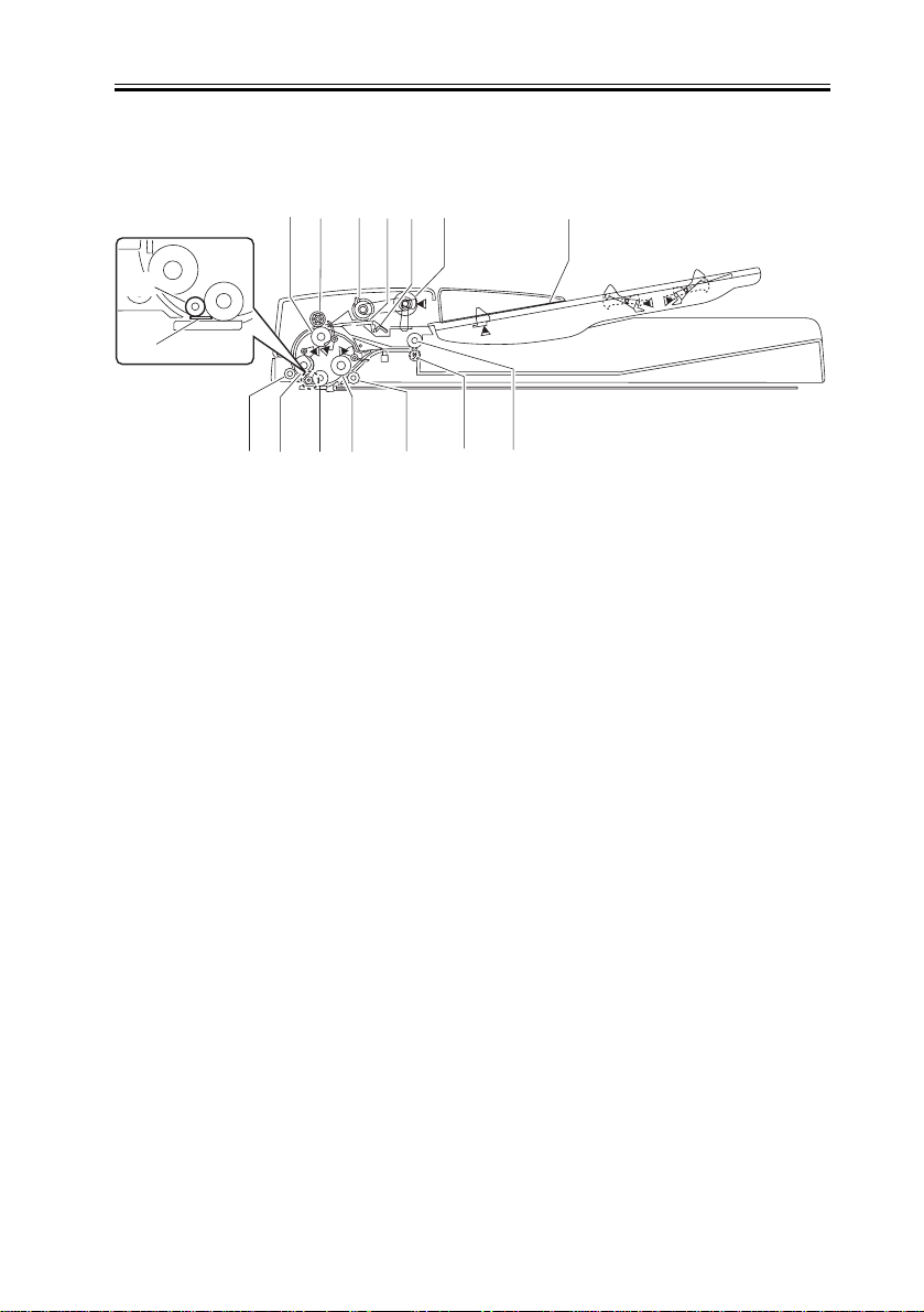
1.2.2 Cross Section
[1] [2] [3]
[13]
[16]
[15]
F-1-2
[1] Registration roller lower)
[2] Registration roller (upper)
[3] Separation roller
[4] Separation pad
[5] Separation plate
[6] Pickup roller
[7] Original pickup tray
[8] Delivery reversing roller (upper)
[9] Delivery reversing roller (lower)
[10] Reading roller 2 spacer
[11] Reading roller 2
[12] Plant roller
[13] Reading spacer
[14] Reading roller 1
[15] Reading roller 1 spacer
[16] White standard sheet
[4]
[10]
[11][12][14]
[5] [6]
[9]
0006-2226
[7]
[8]
1-5
Chapter 1
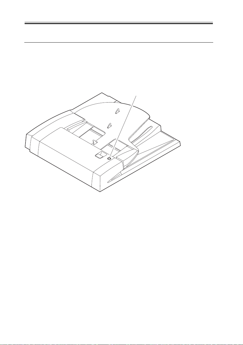
1.3 Using the Machine
1.3.1 Original Placement Indicator
The Original Placement indicator goes on when an original is placed in the original tray,
and flashes in response to an original jam.
Original Placement indicator
F-1-3
1.3.2 Warning and Action to Take
0006-2227
0006-2228
If the Original Placement indicator start to flash while an original is being moved, suspect
a jam, and go through the following steps:
1) Remove all originals from the original tray.
2) Open the feed cover, and remove the jam, if any.
3) Put all originals back in order starting with the 1st original, and put the stack back in the
ADF.
1-6

Chapter 2
Functions

Contents
Contents
2.1 Basic Construction .....................................................................................2-1
2.1.1 Outline of the Electrical Circuitry.......................................................2-1
2.1.2 Inputs to the ADF Controller PCB......................................................2-2
2.1.3 Output for the ADF Controller PCB ...................................................2-3
2.2 Basic Operation..........................................................................................2-4
2.2.1 Transmission of Drive.........................................................................2-4
2.2.2 Outline of the Operation Mode ...........................................................2-6
2.2.3 Normal Rotation Pickup/Delivery (single-sided ................................2-6
2.2.4 Normal Rotation Pickup/Reversal Delivery .......................................2-8
2.2.5 Idle Feed/Pickup/Delivery (double-sided originals .........................2-10
2.2.6 Idle Feeding/Reversal Pickup/Delivery (single- ...............................2-13
2.3 Document Detection.................................................................................2-16
2.3.1 Outline...............................................................................................2-16
2.3.2 Detecting the Presence/Absence of an Original................................ 2-17
2.3.3 Detecting the Last Original ...............................................................2-18
2.3.4 Original Size Initial Identification (feed direction)...........................2-19
2.3.5 Original Size Initial Identification (cross-feed .................................2-20
2.3.6 Slide Guide Positioning Spacer.........................................................2-23
2.3.7 Original Size Final Identification......................................................2-24
2.4 Document Pickup/Separation...................................................................2-27
2.4.1 Basic Operation.................................................................................2-27
2.4.2 Pickup Roller and the Stopper...........................................................2-30
2.4.3 Timing of Pickup ..............................................................................2-31
2.4.4 Controlling the Pickup Motor (M2) ..................................................2-32
2.5 Document Reversing................................................................................2-34
2.5.1 Basic Operation.................................................................................2-34
2.5.2 Sequence of Operation ......................................................................2-36
2.6 Document Feeding/Delivery ....................................................................2-37
2.6.1 Basic Operation.................................................................................2-37
2.6.2 Sequence of Operation ......................................................................2-38
2.6.3 Controlling the Feed Motor (M1) .....................................................2-38
2.7 Detecting Jams ......................................................................................... 2-40

Contents
2.7.1 Jams................................................................................................... 2-40
2.8 Power Supply...........................................................................................2-42
2.8.1 Power Supply.................................................................................... 2-42
2.9 Stamp Operation ...................................................................................... 2-43
2.9.1 Outline............................................................................................... 2-43
2.1 Basic Construction
Chapter 2
2.1.1 Outline of the Electrical Circuitry
0006-2231
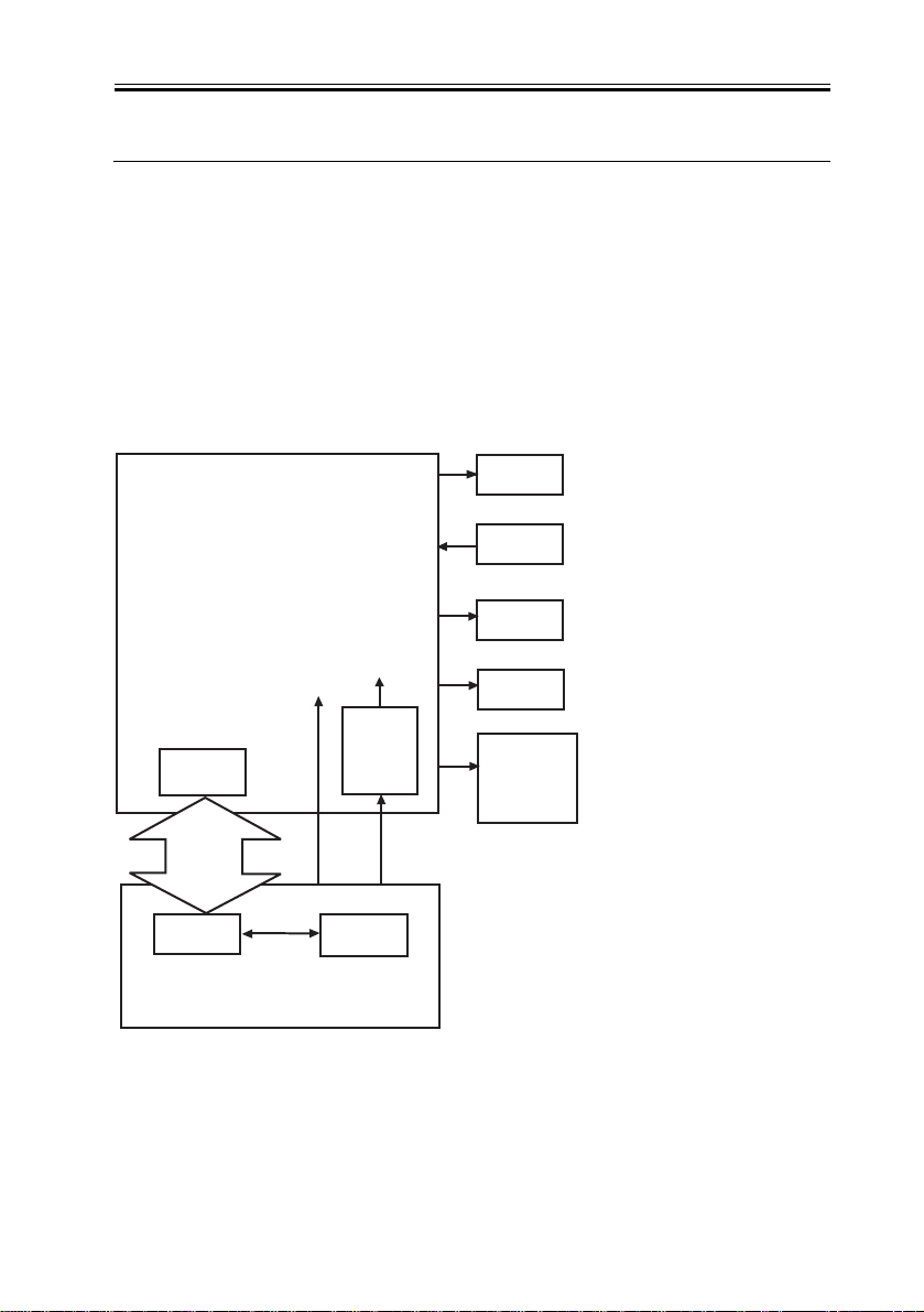
The machine's electrical mechanisms are controlled by its reader controller PCB. The CPU
of the reader unit interprets signals from the sensors and the devices connected to it, and
generates signals used to drive such DC loads as motors and solenoids. The ADF controller
PCB does not have memory areas, and data associated with service mode and the like are
stored in the EEPROM found on the reader controller PCB.
ADF controller PCB
Motors
Senso
Solenoids
+5V
CPU
(IC1)
Serial
communication
+24V
24V
DC5V
Power
supply
J2-2
13V
(IC2)
J1-6
Clutches
Original
Placement
indicator
LED PCB
CPU
Reader controller PCB
F-2-1
EEPROM
2-1
Chapter 2
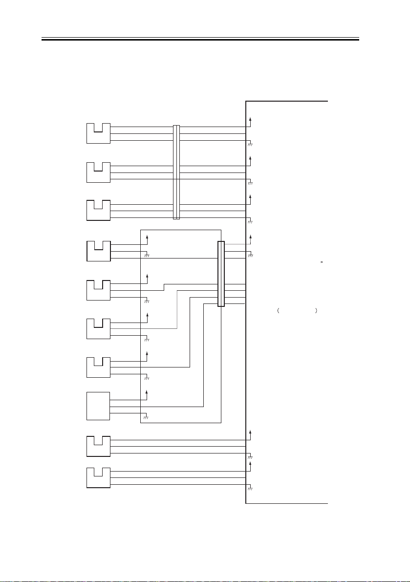
2.1.2 Inputs to the ADF Controller PCB
Inputs to the ADF Controller PCB (1/1)
Registration
paper sensor
Read
sensor
Delivery
reversal
sensor
A4R/LTRR
sensor
Length
sensor 1
Length
sensor 2
PI2
PI3
PI4
PI5
PI6
PI7
J302F
-3
-1
-2
J303F
-3
-1
-2
J304F
-3
-1
-2
J305F
-3
-1
-2
J306F
-3
-1
-2
J307F
-3
-1
-2
J102F
-1
-2
-3
J102F
-4
-6
-5
J102F
-7
-9
-8
+5V
+5V
+5V
J13T
-9
-1
-7
-3
-8
-2
-6
-4
-4
-6
-5
-5
-3
-7
-1
-9
-2
-8
Relay PCB
J101F
ADF controller PCB
+5V
J3F
-1
-3
REGS
-2
+5V
J3F
-4
-6
READS
-5
+5V
J3F
-7
-9
DELIVS
-8
+5V
J5F
-7
-1
-6
-2
-5
-3
A4R/LTR
J6F
-4
-1
LENG1S
-3
-2
LENG2S
-2
-3
ENDS
-1
-4
VR
0006-2232
if paper is present, '0'.
if paper is present, '1'.
if power is present, '1'.
if paper is A4R, '1'.
if paper is LTRR, '0'
if paper is present, '1'
if paper is present, '1'.
if paper is present, '1'.
detects width of original
analog signal
Last
original
sensor
Original
width
volume
Original
payment
sensor
Cover
open/closed
sensor
F-2-2
2-2
PI8
VR1
PI9
PI10
J308F
-3
-1
-2
J309F
-3
-1
-2
J310F
-3
-1
-2
J102F
-10
-12
-11
J102F
-13
-15
-14
+5V
+5V
J4F
J4F
-1
-3
-2
-4
-6
-5
+5V
EMPS
+5V
COVERS
if paper is present, '1'
if cover is opened, '1'
Chapter 2
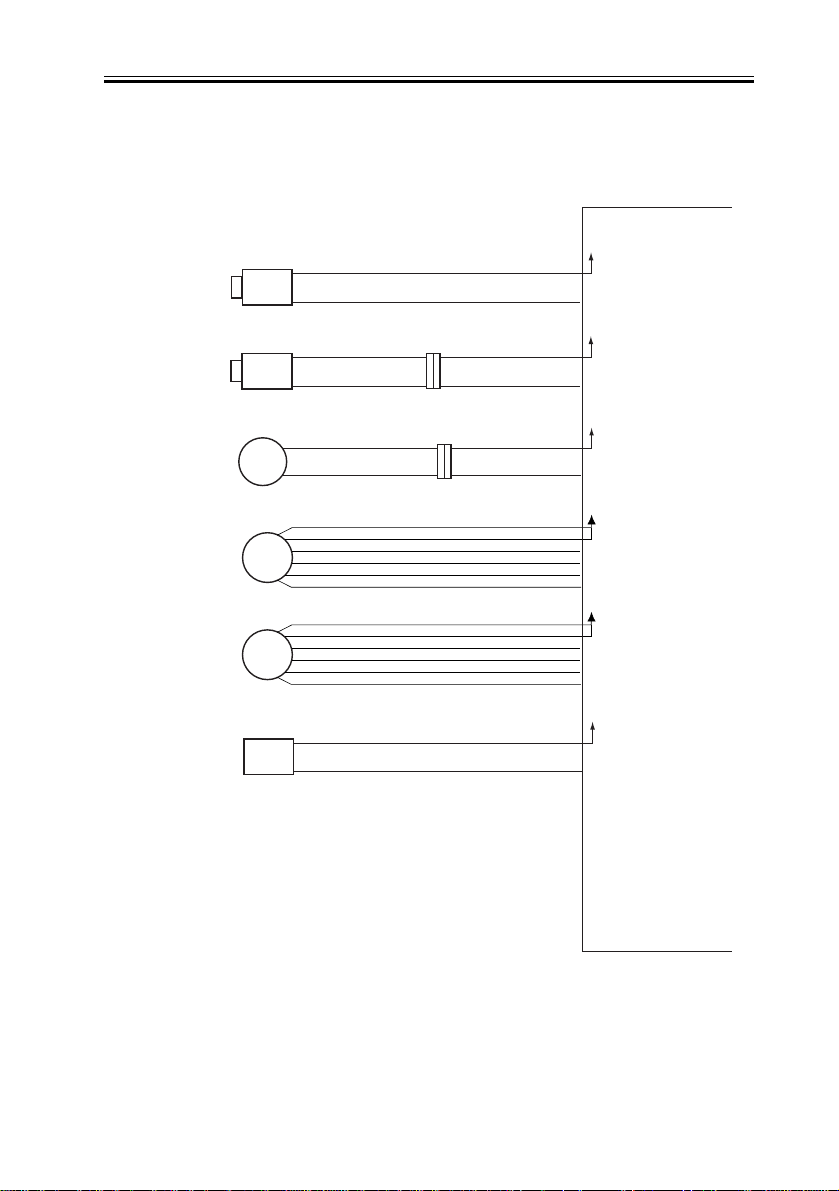
2.1.3 Output for the ADF Controller PCB
Output from the ADF Controller PCB (1/1)
Locking
solenoid
Stamping
solenoid
Pickup clutch
Pickup motor
Feed motor
SL1
SL2
CL1
M2
M1
J14
-1
-2
-2
-1
J16
211
2
0006-2233
ADF controller PCB
+24V
J10
-2
-1
L_SOL when '0', SL2 goes on
+24V
J11
-1
-2
S_SOL
when '0', SL1 goes o
+24V
J11
5
6
J8
-1
-2
-3
-4
-5
-6
J7
-1
-2
-3
-4
-5
-6
CLU
+24V
P_MOT A
P_MOT A*
P_MOT B
P_MOT B*
+24V
R_MOT A
R_MOT A*
R_MOT B
R_MOT B*
when '1', CL1 goes o
n
n
Original Placement
indicator LED
F-2-3
LED
J201
1
2
J11
+5V
-3
-4
LED
when '0', goes on.
2-3

Chapter 2
2.2 Basic Operation
2.2.1 Transmission of Drive
0006-2247
The machine is designed exclusively for stream reading, and uses 2 motors for picking up
and moving originals.
T-2-1
Item (notation) Description
Feed motor (M1) moves originals.
Pickup motor (M2) separates/moves paper.
turns on/off the drive to the separation roller/
Pickup cultch (CL1)
pickup roller using drive from the pickup
motor (M1).
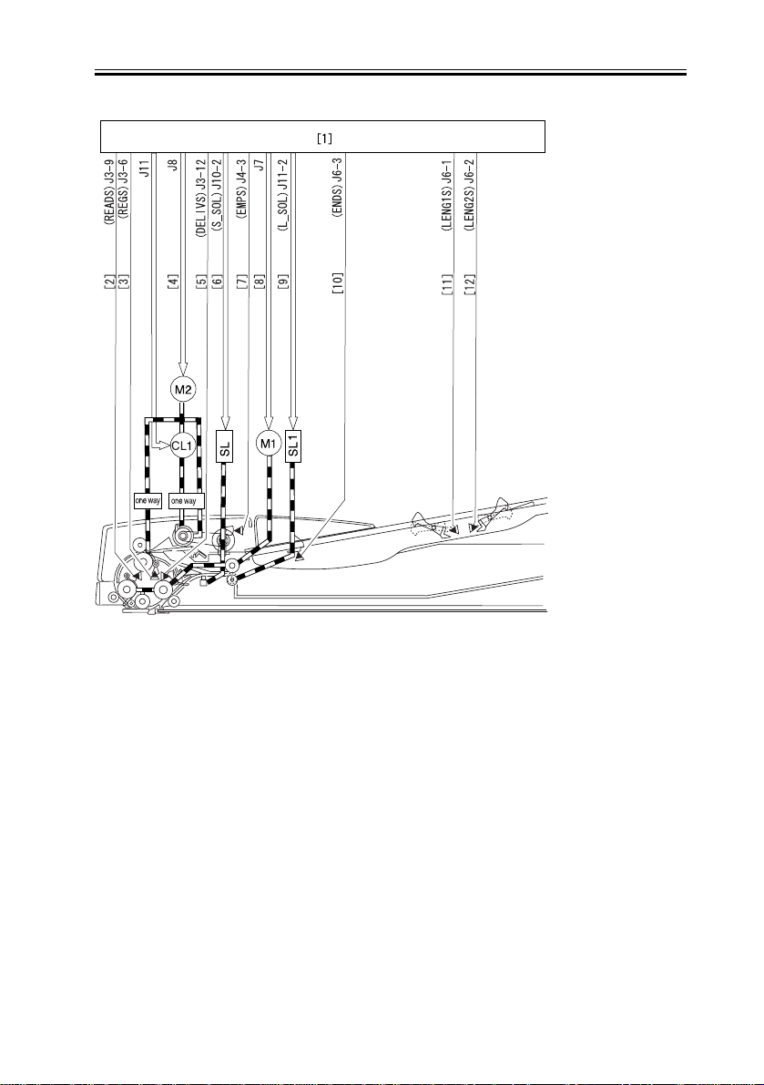
The following is a diagram showing the route of drive transmission in the machine:
2-4
PI3
PI2
PI4
Chapter 2
PI7
PI9
2
PI8
PI6
F-2-4
[1] ADF controller PCB
[2] Original detection signal
[3] Original detection signal
[4] Pickup clutch drive signal
[5] Pickup motor drive signal
[6] Original detection signal
[7] Stamping solenoid drive signal
[8] Original placement signal
[9] Feed motor drive signal
[10] Locking solenoid drive signal
[11] Last original detection signal
[12] Paper size signal 1
[13] Paper size signal 2
2-5

Chapter 2
2.2.2 Outline of the Operation Mode
0006-2248
The machine operates in either of 4 modes, executing each in response to the instructions
from its host machine to generate output. For specifics of each of these modes, see the table
and the charts that follow.
T-2-2
Operation mode Description Print mode
[1]Normal rotation pickup/
delivery
[2]Normal pickup/reversal
delivery
[3]Idle feed/reversal
pickup/reversal delivery
picks up an original; when reading ends,
delivers it as it is.
picks up an original; when reading ends,
turns it over and delivers it.
feeds the original idly to check its size,
feeds the original once again so that
reading will start with the face side, picks
up the original; when reading ends, turns
it over and delivers it.
single-sided original ->
single-sided print
single-sided original ->
double-sided print
double-sided original ->
double-sided print
double-sided original ->
single-sided print
double-sided originals
of mixed sizes ->
double-sided prints
double-sided originals
of mixed sizes -> single-
sided prints
[4]Idle feed/reversal
pickup/delivery
feeds the original idly to check the size,
and reverses it; when reading ends,
delivers it as it is.
single-sided originals of
mixed sizes -> single-
sided prints
single-sided originals of
mixed sizes -> double-
sided prints
2.2.3 Normal Rotation Pickup/Delivery (single-sided
original -> single-sided print)
The original moves as follows:
MEMO
2-6
0006-2249
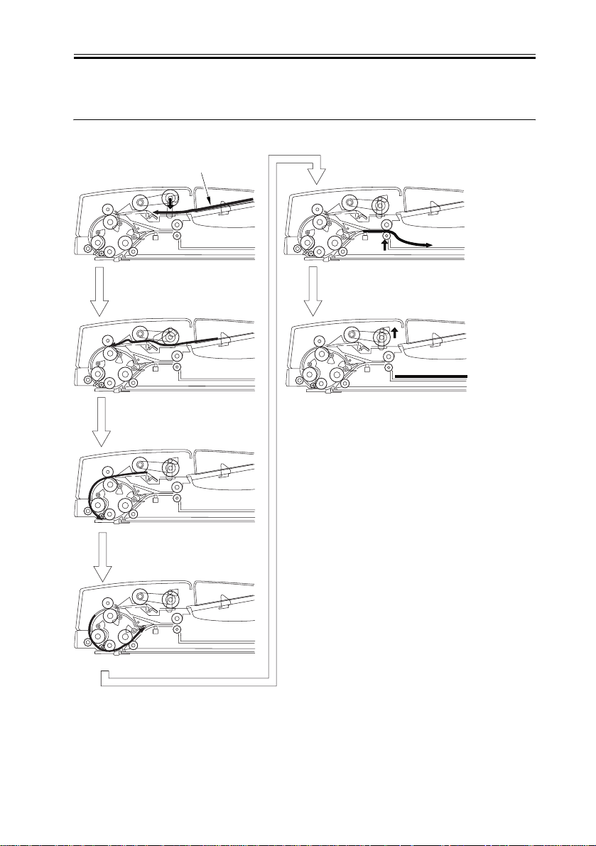
Chapter 2
This operation is also performed when originals with the same width and different lengths
are copied at the 100% scaling ratio.
Original
Pickup
Arching
Standby for reading
Reading
Delivery
Job end
F-2-5
2-7
Chapter 2
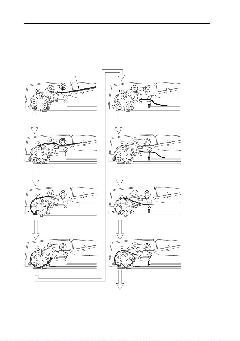
2.2.4 Normal Rotation Pickup/Reversal Delivery
(double-sided original -> doubles-sided print)
The original moves as follows:
Original
Pickup
Arching
0006-2250
Feeding
Reversal
F-2-6
2-8
Standby for reading
Reading
Arching
Standby for reading
To next page
 Loading...