

Page 1
SERIE Z |
Z
SERIES
| SÉRIE Z |
BAUREIHE
Z |
SERIE Z
Documentazione
Tecnica
QUADRO COMANDO
CONTROL PANEL
ARMOIRE DE COMMANDE
SCHALTTAFEL
CUADRO DE MANDO
ZL19N
U33
rev. 0.1
12/2006
©
CAME
CANCELLI
AUTOMATICI
319U33
ITALIANO
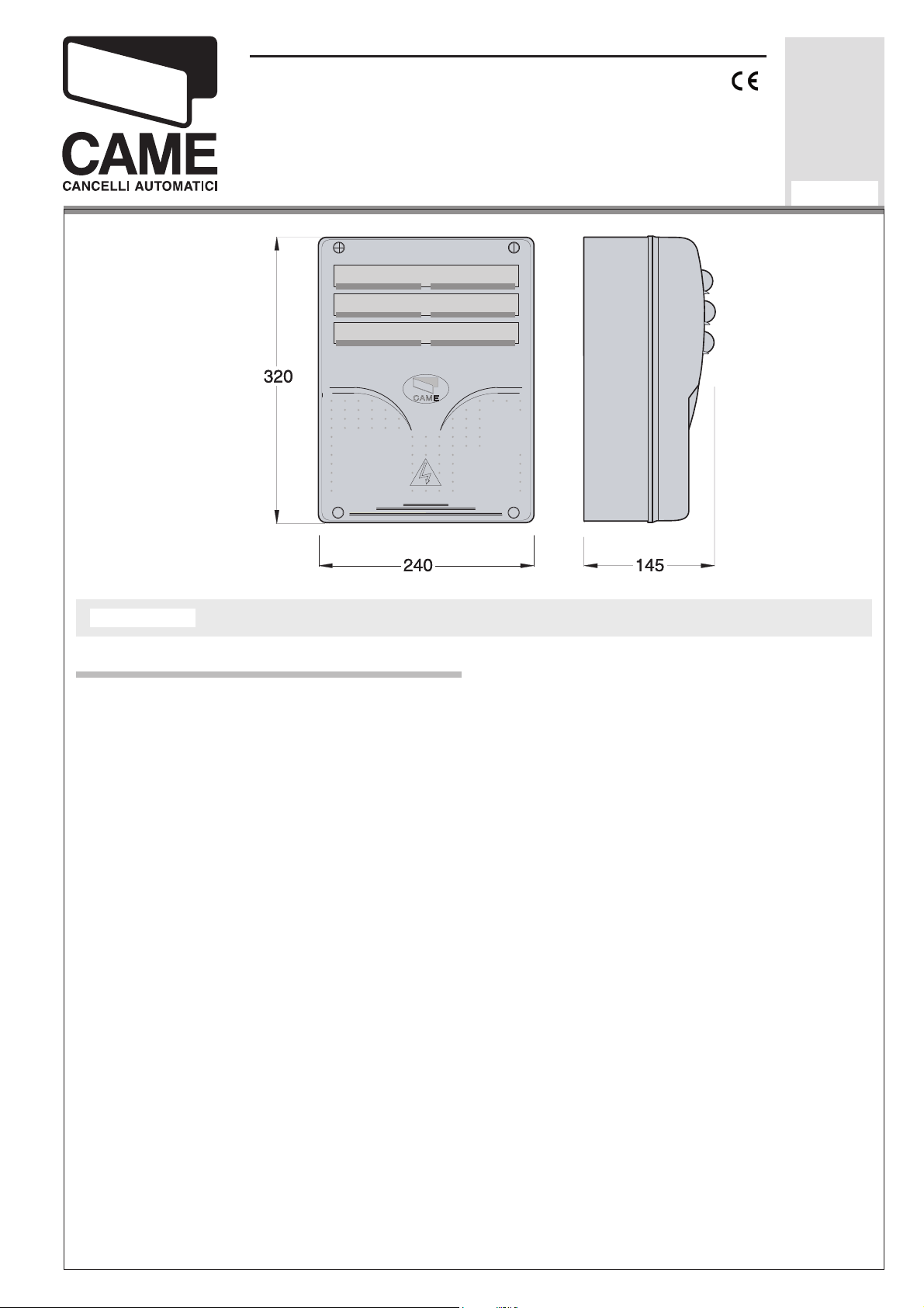
DESCRIZIONE QUADRO COMANDO
CARATTERISTICHE GE NE RA LI
Quadro comando per motoriduttori a
24V con ali men ta zio ne 230V mo no fa se;
fre quen za 50÷60 Hz.
Adatto al comando di motoriduttori serie
FERNI e FROG.
Progettato e costruito interamente dalla
CAME cancelli automatici s.p.a., ri spon de
alle vigenti norme di sicurezza, con grado di
pro te zio ne IP 54. Contenitore in ABS dotato
di presa per il ricircolo dell'aria. Ga ran ti to 24
mesi salvo manomissioni.
Il quadro comando va alimentato con la
ten sio ne di 230V sui morsetti L1 ed L2 ed è
protetto in in gres so con fusibile di linea da
3.15A-F.
I dispositivi di comando sono a bassa
tensione e protetti con fusibile da 315mA-F.
La potenza com ples si va degli ac ces so ri a
24V, protetti da fusibile a 2A-F, non deve
su pe ra re i 40W.
Page 2
->
Le
fotocellule
pre di spo ste per:
• Riapertura in fase di chiusura
le fotocellule rilevando un ostacolo durante la fase di chiusura del cancello,
provocano l’inversione di marcia fi no
alla completa apertura;
SICUREZZA
possono essere col le ga te e
(2-C1),
->
I trasformatori sono dotati di una pro te zio ne che in caso di sovraccarico termico
mantiene le ante aperte.
La richiusura avviene solo dopo che
la tem pe ra tu ra è scesa sotto la soglia di
sovraccarico.
ACCESSORI COLLEGABILI
• Stop parziale
(2-C3), arresto del
cancello se in mo vi men to con con se guen te predisposizione alla chiu su ra
au to ma ti ca;
• Stop totale
(1-2), arresto del cancello
con l'esclusione del ciclo di chiusura
au to ma ti ca; per ri pren de re il mo vi men to bi so gna agire sulla pulsantiera
o sul radiocomando;
->
Il quadro comando include un
amperometrico
dei motori che in ter vie ne
sensore
quan do un ostacolo blocca il mo vi men to in
apertura o in chiu su ra.
Normalmente ne inverte la direzione
di movimento, ma se interviene quando il
cancello si trova nello spazio di 5 cm dalla
battura di chiusura o di apertura, ne arresta
il movimento (vedi anche regolazione del
trimmer OP TIME pag. 27).
->
Lampada di segnalazione
di "cancello
aperto";
->
Lampeggiatore
->
Lampada ciclo
->
Elettroserratura
->
Scheda LB18 per
dian te batteria
di mo vi men to;
.
;
ali men ta zio ne me-
che, in caso di man can za
di energia elettrica, in ter vie ne au to ma ti ca men te. Al ripristino della tensione di linea,
provvede alla ricarica della batteria stessa;
->
Scheda
radiofrequenza
AF (vedi tabella
pag. 30).
FUNZIONI SELEZIONABILI
(vedi pagine da 22 a 26)
La sen si bi li tà del di spo si ti vo è regolabile
me dian te trimmers (vedi pag. 26).
Attenzione! Nel caso venga rilevato per due
volte consecutive un ostacolo in fase di chiusura
(e con funzione Chiusura Automatica attivata),
l’automazione si comporterà nel seguente modo:
1) inverte il moto, aprendo completamente
il cancello;
2) disattiva la Chiusura Automatica;
3) blocca qualsiasi funzione del quadro
comando
Per riattivare l’automazione è necessario dare
un comando di chiusura con i pulsanti collegati
su 2-3, 2-3P e 2-7 (solo pulsante).
-2-
->
Chiusura automatica.
Il temporizzatore di chiu su ra au to ma ti ca
si autoalimenta a fi ne-tempo corsa in aper tu ra.
Il tempo pre fi s sa to regolabile, è co mun que su bor di na to dal l'in ter ven to di even tua li ac ces so ri di sicurezza e si esclude
dopo un intervento di "stop" o in man can za
di energia elettrica;
->
Test di sicurezza fotocellule
.
Ad ogni co man do di apertura e chiu su ra
delle ante, la centralina verifi ca l'effi cenza
delle fotocellule (selettore a 4 dip).
Page 3

->
Rilevazione ostacolo
.
A mo to re fermo (cancello chiuso, aperto
o dopo un co man do di stop totale), im pe di sce qualsiasi mo vi men to se i dispositivi
di sicurezza (es. fotocellule) ri le va no un
ostacolo;
->
Colpo d'ariete.
A ogni co man do di aper tu ra, le ante pre mo no in battuta di chiusura per un se con do,
facilitando l'ope ra zio ne di sgancio dell'elettroserratura;
->
Lampada ciclo
.
Lam pa da che illumina la zona di manovra: rimane accesa dal mo men to in cui le
ante ini zia no l'aper tu ra fi no alla com ple ta
chiusura (com pre so il tempo di chiusura
REGOLAZIONI
->
Trimmer FINE ADJ/AMP SENS = Regolazione fi ne del sensore amperometrico
durante la marcia:
->
Trimmer AMP SENS = Regolazione
min/max
;
sensibilità amperometrica durante la marcia:
min/max
->
Trimmer SLOWDOWN/AMP SENS = Re-
;
golazione sensibilità amperometrica durante
il ral len ta men to:
->
Trimmer ACT = Regolazione tempo chiusura au to ma ti ca:
->
Trimmer DELAY 2M = Ritardo chiusura
del motore M2:
min/max
;
da 2" a 120"
da 1" a 15"
;
;
au to ma ti ca). Nel caso non venga inserita la
chiusura au to ma ti ca, rimane accesa solo
du ran te il mo vi men to (10-E3).
->
Azione mantenuta
.
Fun zio na men to del cancello man te nen do premuto il pul san te (esclu de la
fun zio ne del radiocomando);
->
Prelampeggio
->
Tipo di comando
• «apre-stop-chiude-stop
in aper tu ra e chiusura;
:
» per pul-
san te e/o trasmettitore;
• «apre-chiude-inversione
» per pulsan-
te e/o tra smet ti to re;
• «solo apre
» per trasmettitore.
->
Trimmer OP TIME = Regolazione della
zona di arresto in battuta (vedi pag. 27);
->
Regolazione velocità di marcia e di ral-
lentamento
me dian te connettori faston sulla
scheda (vedi pag. 34);
Attenzione! Prima di interve nire
al l’in ter no del l’ap pa rec chia tu ra, to glie re la
ten sio ne di linea e scollegare le batterie
(se inserite).
-3-
Page 4
ENGLISH
GENERAL CHARACTERISTICS
DESCRIPTION OF CONTROL PANEL
Control panel for 24V d.c. gear motors, pow-
ered by 230V a.c. at 50-60 Hz (single-phase).
Designed to control FERNI and FROG
gear motors.
Designed and built entirely by CAME cancelli automatici s.p.a., it meets regulations in
force and with IP 54 level of protection.
Housing in ABS equipped with vents to
provide internal air circulation. Guaranteed 24
months, unless tampered with.
This control panel is powered by 230V a.c.
across terminals L1 and L2, and is protected
by a 3.15A-F fuse on the main power line.
Control systems are powered by low voltage
and protected by a 315mA-F fuse.
The total power consumption of 24V accessories (which are protected by a 2A-F fuse)
must not exceed 40 W.
SAFETY
->
Photocells
•
Re-opening during the closing cycle (2-
can be connected to obtain:
C1), if the photocells identify an obstacle
while the gate is closing, they will reverse
the direction of movement until the gate
is completely open;
•
Partial stop (2-C3), shutdown of moving gate, with activation of an automatic
closing cycle;
•
Total stop (1-2), shutdown of gate
movement without automatic closing; a
pushbutton or radio remote control must
be actuated to resume movement).
-> The control board includes an
sensor
for the motors which is activated when
amperometric
an obstruction blocks the opening and closing
motions.
The sensor's sensitivity can be adjusted
using the trimmers (see p.
26
).
It normally inverts the direction of movement, but if it activates when the gate is 5 cm
from being fully close or open, it completely
halts the movement (also see adjusting the OP
TIME trimmer page 28).
Warning! If an obstacle is detected two times in
a row during the closing phase (and when the Automatic Closing function is on), the operator will:
1) it inverts the motion, completely opening
the gate;
2) it deactivates the Automatic Closing;
3) Block all functions of the control panel.
To reactivate the operator, send a “close command” by pushing the buttons connected on 2-3,
2-3P and 2-7 (only the button).
-> The transformers are equipped with a
which in case of
thermal over load
will keep the
guard
,
doors open.
They are closed again only after the tem per a ture falls be low the overload thresh old.
ACCESSORIES WHICH CAN BE
CONNECTED TO THIS UNIT
-> “Gate open”
->
Flashing signal light
->
Cycle lamp
->
Electric lock
-> LB18 circuit card for
signal light
when gate is in motion
;
;
emergency battery
,
which is automatically connected in case of
power failure; battery is recharged when line
power is restored
->
Radiofrequency
AF board (see table page
30).
-4-
Page 5

FUNCTIONS AVAILABLE
(see pages 22 through 26)
->
Automatic closing.
timer is automatically activated at the end of
the opening cycle.
The preset, adjustable automatic closing
time is automatically interrupted by the activation of any safety system, and is deactivated
after a STOP command or in case of power
failure;
->
Photocells safety test.
now check the safety system every time an
opening or closing command is given (4 dip
switch selector)
->
Obstacle detection.
stopped (gate is closed, open or half-open after
an emergency stop command), the transmitter
and the control pushbutton will be deactivated
if an obstacle is detected by one of the safety
devices (for example, the photocells);
->
Hammer movement.
tarily press against the closure stops when the
open command is given, which facilitates release
of the electric lock;
.
The automatic closing
The control unit will
When the motor is
The door wings momen-
->
Type of command:
• «
open-stop-close-stop
and radio transmitter;
• «
open-close-reverse
and radio transmitter;
• «
open only
-> Trimmer FINE ADJ/AMP SENS= Fine adjustment of amperometric sensitivity during motor
operation: min/max;
-> Trimmer AMP SENS = Adjustment of amperometric sensitivity during operating: min/max;
-> Trimmer SLOWDOWN/AMP SENS = Adjustment of amperometric sensitivity during
slowdown: min/max;
-> Trimmer ACT = Adjustment of automatic
closing time: 2" to 120";
-> Trimmer DELAY 2M = Delay on closing cycle
motor 2: 1" to 15";
-> Trimmer OP TIME =
zone (open/closed position, see page 28)
» for radio transmitter.
ADJUSTMENTS
» for pushbutton
» for pushbutton
Adjusting of the stop
;
->
Cycle lamp
remains on from the moment the doors begin
to open until they are fully closed (including
the automatic closing time). If automatic closing is not activated, the lamp remains on only
during movement.
->
"Maintained action" function:
only when the pushbutton is held down (the radio
re mo te control system is deactivated);
->
Flashing light
closing cycle begins;
to light the passage area: it
Gate operates
activated before opening and
-> Faston connectors on the circuit card are
used to
speeds
select normal operating and slowdown
(see page 34)
;
Caution! Shut off the mains
power and disconnect the batteries before servicing the inside of the unit.
-5-
Page 6
FRANÇAIS
CARACTÉRISTIQUES GÉNÉRALES
DESCRIPTION ARMOIRE DE COMMANDE
Armoire électrique pour motoréducteurs à
24V c.c. avec alimentation 230V monophasée;
fréquence 50÷60 Hz.
Adaptée à commander les motoréducteurs
de la série FERNI ou FROG.
L’armoire est entièrement conçue et fabriquée par CAME cancelli au to ma ti ci s.p.a. conformément aux normes de sécurité en vigueur
avec un degré de protection IP 54.
Boîtier en ABS muni de prise de circulation
d'air. Garantie 24 mois sauf en cas d’endommagement.
L’armoire de commande doit être alimentée
avec une tension de 230V sur les bornes L1 et
L2 et elle est protégée en entrée par un fusible
de ligne de 3.15A-F. Les dispositifs de commande sont à basse tension et protégés avec
un fusible de 315mA-F. La puissance totale des
accessoires en 24V, protégés par un fusible de
2A-F, ne doit pas dépasser 40W.
SÉCURITÉ
-> Il est possible de brancher des
les
et de les programmer pour:
photocellu-
• Réouverture en phase de fermeture
(2-C1), les cellules photoélectriques provoquent l’inversion de marche jusqu’à
l’ouverture complète si elles relèvent un
obstacle durant la phase de fermeture
du portail ;
• Stop partiel
(2-C3), arrêt du portail et
fermeture automatique ;
• Stop total
(1-2), arrêt du portail et
désactivation d’un éventuel cycle de
fermeture automatique; pour activer de
nouveau le mouvement, il faut agir sur
les boutons-poussoirs ou sur la radiocommande
.
-> L’armoire de commande contient un
ampérométrique
des moteurs qui intervient
capteur
lorsqu’un obstacle bloque le mouvement en
ouverture ou en fermeture.
La sensibilité de ce dispositif est réglable
au moyen trimmers (voir p. 26).
Normalement il sert pour invertir la direction du mouvement, mais s’il intervient lorsque
le portail se trouve à 5 cm. de la butée de
fermeture ou d’ouverture, il en arrête le mouvement (voir aussi réglage du trimmer OP
TIME page 28).
Attention ! Au Au cas où un obstacle serait détecté deux fois de suite au cours de la fermeture (et
avec la fonction Fermeture Automatique en activité),
l’automatisme procèdera de la façon suivante :
1) il invertit le mouvement en ouvrant complètement le portail ;
2 ) il arrête la Fermeture Automatique ;
3) il bloque absolument toutes les fonctions
de l’armoire de commande.
Pour remettre en marche l’automatisme il faut
donner une commande de fermeture avec les boutons
connectés sur 2-3, 2-3P et 2-7 (bouton-poussoir
seulement).
-> Les transformateurs sont dotés d’une
tec tion
qui en cas de
surcharge ther mi que
pro-
garde les portes ouvertes.
Le renouvellement de la fermeture s’effectue seulement lorsque la température est descendue au-dessous du seuil de surcharge.
ACCESSOIRES POUVANT ÊTRE BRANCHÉS
->
Lampe de signalisation
Clignotant de mouvement
->
->
Lampe cycle
->
Serrure électrique ;
.
de “portail ouvert” .
.
-6-
Page 7
-> Carte LB18 pour l’
alimentation par batterie
intervenant automatiquement en cas d’absence
d’énergie électrique, au rétablissement de la
tension de ligne, la carte procède au rechargement de la batterie ;
-> Carte
radiofréquence
AF (voir tableau pag.
30).
FONCTIONS POUVANT ÊTRE SÉLECTIONNÉES
(voir les pages de 22 à 26)
-
>
Fermeture automatique.
Le temporisateur de
fermeture automatique est autoalimenté à la fi n
du temps de la course en ouverture.
Le temps réglable est programmé, cependant, il est subordonné à l’intervention
d’éventuels accessoires de sécurité et il est
exclu après une intervention de “stop” ou en
cas de coupure de courant;
->
Fonction “Action maintenue”
. Fonctionnement du portail en maintenant appuyé
le bouton-poussoir (exclut la fonction de la
radiocommande) ;
Préclignotement
->
en ouverture et en fer-
meture;
ype de commande:
-> T
• «ouverte-stop-fermée-stop» pour bouton-poussoir et émetteur radio;
• «ouverture - fermeture - inversion
» pour
bouton-poussoir et émetteur radio;
• «seulement ouverture
» pour émetteur
ra dio;.
RÉGLAGES
->
Trimmer FINE ADJ/AMP SENS = Réglage
fi n du capteur ampèremétrique pendant le
fonctionnement: min./max.;
Test de sécurité photocellules.
->
Cela permet
au boîtier de vérifi er le bon fonctionnement
des despositifs de securité aprés chaque
commande d'ou ver tu re ou de fermeture (sélecteur à 4 dip);
Détection obstacle.
->
Quand le moteur est
arrêté (portail fermé, ouvert ou semi-ouvert,
cette position est obtenue avec une commande
de stop total), annule toute fonction de l’émetteur ou du bouton-poussoir en cas d’obstacle
détecté par les dispositifs de sécurité (ex.
Photocellules) ;
Coup de bélier.
->
Á chaque commande
d’ouverture, les vantaux se portent en butée
de fermeture pendant une se con de, facilitant
ainsi l’opération de déblocage de la serrure
électrique;
Lampe cycle
->
pour éclairer la zone de
manœuvre: elle reste allumée à partir du moment où les vantaux commencent à s’ouvrir
jusqu’à la fermeture complète (y compris le
temps de fermeture automatique). Elle ne
reste allumée que durant le mouvement si la
fermeture automatique n’est pas activée.
->
Trimmer AMP SENS = Réglage sensibilité
ampèrométrique pendant le mouvement :
min./max;
->
Trimmer SLOWDOWN/AMP SENS = Réglage sensibilité ampèrométrique pendant le
ralentissement : min./max;
->
Trimmer ACT = Temps de fermeture auto-
matique: de 2 à 120";
->
Trimmer DELAY 2M = Retard fermeture
moteur 2: de 1" à 15";
->
Trimmer OP TIME = Réglage de
l’emplacement d’arrêt en butée (voir page
28);
->
Réglage vitesse de mouvement et de ralentissement
à l'aide de connecteurs rapides
placés sur carte (voir page 34).
Attention! Avant d’intervenir à
l’intérieur de l’appareillage, couper la tension de ligne et débrancher les batteries
(si branchées).
-7-
Page 8
DEUTSCH
ALLGEMEINE MERKMALE
BESCHREIBUNG DES STEUERGERÄTS
Schalttafel für 24-V-Gleichstrom-Getriebemotoren mit 230-V-Einphasen strom versorgung;
Frequenz: 50-60 Hz.
Zur Steuerung von Getriebemotoren der
Baureihen FERNI und FROG.
Vollkommen von der CAME cancelli automatici s.p.a. den geltenden Sicherheitsnormen entsprechend entwickelt und hergestellt.
Schutzgrad: IP 54. ABS-Gehäuse mit Luftklappe. 24 Monate Garantie, vorbehaltlich unsachgemäßer Handhabung und Montage.
Die Schalttafel wird mit einer Spannung
von 230V über die Klemmen L1 und L2 gespeist und ist am Eingang mit einer 3.15A-FHauptsicherung. Die Steuerungen erfolgen
mit Niederspannung und geschützen enie
315mA-F-Sicherung. Die Gesamtleistung des
durch eine 2A-F-Sicherung geschützten 24-VZubehörs darf 40W nicht überschreiten.
SICHERHEITSVORRICHTUNGEN
-> Die
Lichtschranken
können für folgende
Funktionen angeschlossen bzw. vorbereitet
werden:
• Wiederöffnen beim Schließen
(2-C1),
die Lichtschranken ermitteln ein Hindernis während des schließens vom Tor und
lösen die Umkehr der Laufrichtung vom
Tor aus, bis dieses wieder vollständig
geöffnet ist;
• Teilstop
(2-C3), Stillstand des Tores
während des Torlaufs, mit darauffolgender automatischer Torschließung;
• Totalstop (1-2), sofortiger Stillstand
des Tores mit Ausschluß eventueller
Schließautomatik: Fortsetzung des
Torlaufs über Drucktaster- bzw. Funksendersteuerung;
Die Empfi ndlichkeit der Vorrichtung kann
mithilfe eines Trimmers eingestellt werden
(siehe Seite
26
).
Normalerweise wird der Torlauf reversiert,
doch wenn der Torfl ügel nur 5 cm von den
Toranschlägen entfernt ist, wird der Torlauf
unterbrochen (siehe auch Einstellung des
Trimmers OP TIME auf Seite 28).
Achtung! Sollte während des Zulaufs zweimal
hintereinander ein Hindernis erfasst werden (bei
aktiviertem Autozulauf), bewirkt der automatische
Antrieb folgendes:
1) Reversierung bis zur völligen Toröffnung;
2) Deaktivierung des Autozulaufs;
3) Jede Funktion der Steuerung wird blockiert.
Um den Antrieb wieder zu reaktivieren muss mit
den auf 2-3, 2-3P und 2-7 (nur Schalter) angeschlossenen Tastern ein Zu-Befehl gegeben werden.
-> Die Transformatoren sind mit einer Sicherung ausgestattet, die bei Wärmestau dafür
sorgt, daß die Torfl ügel offen bleiben.
Das Tor schließt erst wieder, wenn die
Temperatur unter das Niveau der Überladung
abgesunken ist.
ANSCHLIEßBARES ZUBEHÖR
->
Anzeigeleuchte
Blinkleuchte
->
für “Tor offen”;
“Tor in Bewegung”;
-> Betriebszyklus-Anzeigeleuchte
->
Elektroschloß;
-> Steckplatine LB18 für
Notbatterie
, die sich bei Stromausfall automa-
Stromversorgung über
tisch zuschaltet und die Bat te rie bei erneuter
Netz-Stromversorgung wieder aufl ädt.
Funkfrequenz-Platine
->
AF (siehe Tabelle
Seite 30)
-> Motorsteuerung mit integriertem
perometrischen Fühler
der Motoren, zur
Unterbrechung von Auf- und Zulauf bei Hinderniserfassung.
-8-
am-
Page 9
WAHLFUNKTIONEN
(siehe Seiten 22 bis 26)
-
>
Schließautomatik
. Der SchließautomatikZeischalter speist sich beim Öffnen am Ende
der Torlaufzeit selbst . Die voreingestellte Zeit
ist auf jeden Fall immer dem Eingriff eventueller Sicherheitsvorrichtungen untergeordnet
und schließt sich nach einem “Stop”-Eingriff
bzw. bei Stromausfall selbst aus;
-
>
Sicherheitstest der Lichtschranken.
Dadurch besteht die Möglichkeit, die Leistungsfähigkeit der Sicherheits vorrichtungen
nach jeder Öffnungs-und Schließsteuerung
zu überprüfen (
-
>
Hinderniserfassung
4 Dip-Auswahltaster
. Bei stillstehendem
).
Motor (Tor geschlossen, geöffnet oder durch
eine Totalstop-Steuerung halb geöffnet) wird
bei durch die Sicherheitsvorrichtungen (z.B.:
Lichtschranken) erfaßtem Hindernis jede Sender- oder Drucktasterfunktion annulliert;
-
>
Widderstoß
. Bei jeder Öffnungssteuerung
üben die Torfl ügel eine Sekunde lang einen
leichten Druck auf den Schließungsendanschlag aus und erleichtern dadurch die
Entriegelung des Elektroschlosses;
->
Steuerart
:
• «Öffnen-Stop-Schließen-Stop» für
Drucktaster- und Funksendersteuerart;
•
«Öffnen-Schließen-Torlaufumsteuerung» für Drucktaster und Funksendersteuerart;
•
«nur Öffnen» für Funksendersteuerart.
EINSTELLUNGEN
->
Trimmer FINE ADJ/AMP SENS = Feineinstellung des amperemetrischen Sensors
während des Torlaufs: min/max;
->
Trimmer AMP SENS = Einstellung der
amperemetrischen Empfi ndlichk eit während
Laufgeschwindigkeit: min/max;
->
Trimmer SLOWDOWN/AMP SENS = Einstellung der amperemetrischen Empfi ndlichk
während Laufverlangsamung: min/max;
->
Trimmer ACT = Zeiteinstellung Schließautomatik: von 2" bis 120",
->
Trimmer DELAY 2M = Schließverzögerung
Motor 2: von 1" bis 15";
->
Trimmer OP TIME = Einstellung des Toran-
-> Betriebszyklus-Anzeigeleuchte. Das Licht,
das den Torbereich beleuchtet, bleibt vom
Beginn des Öffnens bis zum vollständigen
Schließen der Torfl ügel eingeschaltet (einschließlich Wartezeit für automatisches
Schließen). Wenn das automatische Schließen
nicht zugeschaltet ist, bleibt das Licht nur
während der Torbewegung eingeschaltet
(10-E3)
->
;
Funktion “Aktion wird beibehalten”
. Torbetrieb durch Druck tasterbetätigung (Funkfernsteuerung ausgeschlossen);
->
Vorblinken
beim Öffnen und Schließen;
schlages (siehe Seite 28);
->
Einstellung der Laufgeschwindigkeit und
Einstellung der Laufverlangsamung
über Fas-
ton-Verbinder auf Platine (siehe Seite 34).
Achtung! Das Gerät vor Eingrif-
fen im inneren spannungsfrei schalten
und die Stromzufuhr mittels Batterien
(falls zugeschaltet) unterbrechen.
-9-
Page 10
ESPANOL
CARACTERISTICAS GENERALES
DESCRIPCIÓN CUADRO DE MANDO
Cuadro eléctrico para motorreductores a
24V d.c. con alimentación 230V monofase:
frecuencia 50÷60 Hz.
Adecuado para el mando de motorreductores serie FERNI y FROG.
Diseñado y fabricado enteramente por
CAME cancelli automaticI S.P.A., cumple con
las normas de seguridad vigentes, con gra do
de protección IP 54. Caja de ABS, dotada de
toma para la recirculación de aire. Garantizado
24 meses salvo manipulaciones.
El cuadro de mando se alimenta con una
tensión de 230V en los bornes L1 y L2 y está
protegido en entrada con fusible de línea de
3.15A-F. Los dispositivos de mando son a
baja tensión y està protegidos por fusible a
315mA-F. La potencia total de los accesorios
a 24V, protegidos por fusible a 2A-F, no debe
superar los 40W.
SEGURIDAD
La sensibilidad del dispositivo puede regu-
larse me dian te unos trimmer (ver pág.
26
).
Normalmente invierte la dirección de movimiento, pero si interviene cuando la cancela
está a 5 cm del tope de cierre o de apertura,
detiene el movimiento (véase también regulación del trimmer OP TIME pág. 28).
¡Atención! Si se detectase dos veces consecutivas un obstáculo en fase de cierre (y con función
Cierre Automático activada), la automatización se
comportará de la siguiente manera:
1) invierte el movimiento, abriendo completamente la cancela;
2) desactiva el Cierre Automático;
3) bloquea cualquier función del cuadro de
mando.
Para reactivar la automatización es necesario dar
un mando de cierre con los pulsadores conectados
en 2-3, 2-3P y 2-7 (sólo pulsador).
-> Los transformadores están provistos de una
protección que ante una so bre car ga térmica
mantiene abiertas las ho jas.
-> Las
fotocélulas
pueden estar conectadas y
predispuestas para:
• Reapertura en la fase de cierre (2-C1),
las fotocélulas detectan un obstàculo
durante el cierre de la puerta, provocando la inversión de marcha hasta la
apertura completa;
• Parada parcial
(2-C3), parada de la
puerta si se encuentra en movimiento
con la consiguiente predisposición al
cierre automático;
• Parada total
(1-2), parada de la puerta excluyendo el posible ciclo de cierre
automático; para reactivar el movimiento
es preciso actuar en el teclado o en el
man do a distancia);
-> El cuadro de mando incluye un
amperomérico
de los motores que se acciona
sensor
cuando un obstáculo bloquea el movimiento en
las fases de apertura y cierre
El recierre se verifi ca recién después que
la temperatura ha descendido por debajo del
nivel de sobrecarga.
ACCESORIOS CONECTABLES
->
Lámpara de señal
Lámpara intermitente
->
Lámpara ciclo
->
Cerradura eléctrica
->
-> Tarjeta LB18 para la
batería
que, en caso de falta de energía eléc-
de “puerta abierta”;
de movimiento;
.
;
alimentación me dian te
trica, interviene automáticamente; una vez
conectada de nuevo la tensión de línea, se
ocupa de cargar la batería misma;
-> Tarjeta
radiofrecuencia
AF (ver tabla pág.
30).
-10-
Page 11

FUNCIONES SELECCIONABLES
(véase desde las páginas 26 a 30)
->
Cierre automático
. El temporizador de
cierre automático se au to a li men ta en fi n-detiempo carrera en fase de aper tu ra. El tiempo
prefi jado regulable, sin embargo, está subordinado a la intervención de posibles accesorios
de seguridad y se excluye después de una
intervención de parada o en caso de falta de
energía eléctrica;
->
Test de seguridad fotocélulas.
Permite a la
central comprobar la efi ciencia en los dispositivos de seguridad después de cada co man do
de apertura y cierre (
->
Detección obstáculo.
selector de 4 dip
Con el motor parado
).
(puerta cerrada, abierta o en posición semiabierta obtenida a través de un co man do
de stop total), anula cualquier función del
transmisor o del botón en caso de obstáculo
detectado por los dispositivos de seguridad
(por ejemplo: fotocélulas);
->
Tipo de mando;
• «apertura-parada-cierre-parada» para
tecla y transmisor de radio;
• «apertura-cierre-inversión
» para tecla
y transmisor de radio;
• «sólo apertura
» para transmisor de
ra dio.
REGULACIONES
->
Trimer FINE ADJ/AMP SENS = Regulación
fi n del sensor amperimétrico du ran te la marcha: mín./máx.;
->
Trimer AMP SENS = Regulación sensibilidad amperimétrica du ran te la marcha:
mín/máx;
->
Trimer SLOWDOWN/SENS = Regulación
sensibilidad amperimétrica du ran te el ralentamiento: mín/máx;
->
Trimer ACT = Tiempo cierre automático:
de 2" a 120”;
->
Golpe de ariete.
En cada co man do de apertura las puertas presionan el tope del cierre
durante un segundo, fa ci li tan do la operación
de desenganche de la electrocerradura);
->
Lámpara ciclo
para iluminar la zona de
maniobra: queda encendida desde cuando
las hojas comienzan a abrirse hasta que se
cierran por completo (incluido el tiempo de
cierre automático). Si no se conectara el cierre
automático, queda encendida sólo durante el
movimiento
Función "Acción mantenida"
->
;
. Funcionamiento de la puerta manteniendo pulsada
la tecla (excluye la función del man do a
distancia);
->
Preintermitencia
en fase de apertura y
cierre;
->
Trimer DELAY 2M = Retraso cierre motor
2: de 1" a 15”;
->
Trimer OP TIME = Regulación de la zona
de parada en el tope (véase pág. 28);
->
Regulación velocidad de marcha y de ra-
lentamiento
me dian te conectores faston en
tarjeta (véase pág. 34).
¡Atención! Antes de actuar den-
tro del aparato, quitar la tensión de línea
y desecnectar las baterías (si estuvieran
conectadas).
-11-
Page 12

SCHEDA BASE -
F
21
A
B
C
D
E
F
G
H
I
L
M
N
L_ 5 31
N
E
C
A
L
A
A
2
A
.
A
A
7
E
A
D
-
.
N
.
.
O
W
N
1
E
D
1
O
N
2
N
2
V
4
V
F
D
N
1
2
3
4
5
6
7
8
9
1
0
1
1
1
2
0
5
0
6
0
7
0
8
0
9
V
4
V
5
V
6
V
7
V
8
A
E
1
!
M
1
N
2
T
N
1
2
L
3
S
2
3
2
2
2
C
1
C
C
1
1
C
.
7
1
3
1
2
3
-
M
.
E
D
I
S
.
2
7
7
5
1
0
0
2
4
N
X
N
X
0
0
2
4
N
X
N
X
MOTHERBOARD
0
22330
112
- CARTE BASE -
2
GRUNDPLATINE
22330
112
- TARJETA BASE
224
LL..MMIIN
22330
LLLLAAX
VVEELL..MMIIN
2
N
MMOOTTOORR2
FFUUSSEE1100A
EELL..MMAAX
3
AABBCCDDEEFFGGHHIILLRR11RR2
V
V
4
CCOONNTTRROOLLBBOOAARRD
1
AACCCCEESSSSOORRIIEESSFFUUSSEE22A
4
EELLEECCTTRRIIC
LLOOCCKKFFUUSSEE22A
TTT
MMOOTTOORR1
FFUUSSEE1100A
SS..22777
1
N
2
W
N
O
1
O
D
E
ZZLL1199N
17
0
5
22
0
6
1
0
2
7
3
0
8
4
0
5
9
6
7
V
8
4
9
V
5
1
0
V
6
1
1
V
1
7
2
V
8
WWAARRNNIINNGG!
LLN
LLIINNE
FFUUSSE
112200VV==55A
223300VV==33,,1155A
12
23
4321
8765
109
20
O
N
C
RRCC1
RRAA1
RRAA22RRCC2
13
C
18
FFAA11FFCC1
ZZLL1199NNA
ZZLL1199UUL
14
C
FFAA22FFCC22C
CCHH11CCHH2
++--OOPP..TTIIMME
M
6
9
10
++-
DDEELLAAYY22M
++--AA..CC..TT.
2
1
2
N
1
1100111
224
RRAALLLL..MMIIN
RRX
EELL..MMIIN
..MMAAX
521
CCOONNTTRROOLLBBOOAARRD
FFUUSSEE331155mmA
FFIINNEEAADDJJ.
AAMMPP..SSEENNSS.
AAMMPP..SSEENNSS.
++--++--++-
7
11
1234
NO
BB11//BB2
++AALL//EE3
15
3
CC1
33PP7
++AAL
EESS55BB11BB2
EE3
CC3
TTS
SSLLOOWWDDOOWWN
AAMMPP..SSEENNSS.
19
1
5
7
7
2
.
S
I
D
16
8
AAF
-12-
Page 13

IT
PRINCIPALI COMPONENTI
EN
MAIN COMPONENTES
1) Trasformatori
2) Connettori regolazione velocità
3) Morsettiera per il collegamento al
caricabatterie LB18 (se non utilizzata,
assicurarsi che i ponticelli siano
collegati tra A-B; C-D; E-F; G-H)
4) Fusibile accessori 2A-F
5) Fusibile centralina 315mA-F
6) Trimmer di regolazione fi ne della
sen si bi li tà amperometrica durante la
marcia
7) Trimmer di regolazione sensibilità
amperometrica durante la marcia
8) Trimmer di regolazione sensibilità
amperometrica durante il ral len ta men to
9) Trimmer di regolazione della zona di
arresto in battuta
10) Trimmer di regolazione chiusura
au to ma ti ca
11) Trimmer di regolazione ritardo chiu su ra
2° motore
12) Selettore funzioni a 10 dip (vedi pagina
24)
13) LED di segnalazione codice radio/
con teg gio tempo ACT
14) Pulsanti memorizzazione codice
15) Jumper selezione uscita
B1-B2 / lampada ciclo
16) Innesto scheda radiofrequenza
17) Fusibile di linea 3.15A-F
18) Morsettiera di collegamento
19) Selettore funzioni a 4 dip (vedi pagina
23)
20) Jumper selezione tipo di comando per
pulsante 2-7
21) Fusibile elettroblocco 2A-F
22) Fusibile motore n°1 10A-F
23) Fusibile motore n°2 10A-F
1) Transformer
2) Connectors for speed selection
3) Terminal board for connectiong battery
charger LB18 (connect a bridge across
terminala A-B; C-D; E-F; G-H if battery
charger is not used)
4) Fuse on accessory power line, 2A-F
5) Fuse on central control unit, 315mA-F
6) Fine adjustment of amperometric
sensitivity during motor operation
7) Trimmer for adjustment of
amperometric sensitivity during
operation
8) Trimmer for adjustment of
amperometric sensitivity during
slowdown
9) Trimmer to adjust the stop zone (open/
closed position)
10) Trimmer for adjustment of automatic
closing
11) Trimmer for adjustment of delay on
closing cycle motor n.2
12) 10-dip function switch (see pag.24)
13) Radio code/automatic closing signal
LED
14) Button for memorizing code numbers
15) Jumper which selects output
B1-B2 / operating cycle indicador light
16) Radiofrequency board socket
17) Line fuse, 3.15A-F
18) Terminal block for external conections
19) 4-dip function switch (see pag.23)
20) Jumper for selection of type of control
for button in 2-7
21) Electric lock fuse 2A-F
22) Fuse motor n°1 10A-F
23) Fuse motor n°2 10A-F
-13-
Page 14

FR
PRINCIPAUX COMPOSANTS
DE
HAUPTKOMPONENTEN
1) Transformateur
2) Connecteurs réglage vitesse
3) Plaque à bornes pour le branchement
au chargeur de batteries LB18 (si elle
n'est pas utilisée, s'assurer que les
pontets sont branchés entre A-B; C-D;
E-F; G-H)
4) Fusible accessoires 2A-F
5) Fusible boîtier 315mA-F
6) Trimmer de réglage fi n de la sensibilité
ampèremétrique pendant le fonctionnement
7) Trimmer de réglage sensibilité am-
pèremétrique pendant le mouvement
8) Trimmer de réglage sensibilité am-
pèremétrique pendant le ralentissement
9) Trimmer de réglage de l’emplacement
d’arrêt en butée
10) Trimmer de réglage fermeture automa-
tique
11) Trimmer de réglage retard fermeture
moteur 2
12) Selecteur de fonctions à 10 interrup-
teurs à positions multiples (voir pag.25)
13) LED de signalisation code radio/
comptage temps TCA
14) Bouton-poussoir mémorisation code
15) Pontet sélection sortie B1-B2 / lampe
cycle
16) Branchement carte radiofréquence
17) Fusible de ligne 3.15A-F
18) Plaque à bornes de connexion
19) Selecteur de fonctions à 4 interrupteurs
à positions multiples (voir pag.23)
20) Pontet de sélection type de commande
pour bouton-poussoir en 2-7
21) Fusible du serrure electronique 2A-F
22) Moteur fusible n°1 10 A-F
23) Moteur fusible n°2 10 A-F
1) Transformatoren
2) Verbinder für Geschwin digkeits ein-
stellung
3) Klemmleiste für den Anschluß an das
Batterieladegerät LB18 (bei Nichtverwendung überprüfen, ob A-B, C-D,
E-F, G-H gebrückt sind)
4) Zubehör-Sicherung 2A-F
5) Schaltkastensicherung 315mA-F
6) Trimmer zur Feineinstellung des am-
peremetrischen Sensors während des
Torlaufs: min/max;
7) Trimmer zur Einstellung amperemetri-
schen Empfi ndlichkeit während Laufgeschwindigkeit
8) Trimmer zur Einstellung ampereme-
trischen Empfi ndlichkeit während
Laufverlangsamung
9) Trimmer zur Einstellung des Toransch-
lages
10) Trimmer zur Einstellung der Schließau-
tomatik
11) Trimmer zur Einstellung Schließverzö-
gerung Motor 2
12) Wählschalter für Funktionen mit 10 Dip.
(Siehe Seite 25)
13) Schließautomatik/Anzeige LED-
Funkcode
14) Code-Speichertasten
15) Jumper zur Wahl des Ausgangs
B1-B2 / Betriebszyklus Anzeigeleuchte
16) Steckanschluß Funkfrequenz-Platine
17) Hauptsicherung 3.15A-F
18) AnschlußKlemmenleiste
19) Wählschalter für Funktionen mit 4 Dip.
(Siehe Seite 23)
20) Steuerart-Wahljumper für Taste auf 2-7
21) Schmelz elektronische schloss 2A-F
22) Schmelz Motor n°1 10A-F
23) Schmelz Motor n°2 10A-F
-14-
Page 15

ES
PRINCIPALES COMPONENTES
1) Transformadores
2) Conectores regulación velocidad
3) Caja de bornes para la conexión del
cargador de batería LB18 (si no se
usa, asegurarse de que los puentes
están conectados entr A-B, C-D, E-F,
G-H)
4) Fusible accesorios 2A-F
5) Fusible para central 315mA-F
6) Trimer de regulación fi n de sensibilidad
amperimétrica durante la marcha
7) Trimer de regulación sensibilidad am-
perimétrica durante la marcha
8) Trimer de regulación sensibilidad
amperimétrica durante el ralentamiento
9) Trimmer de regulación de la zona de
parada en el tope
10) Trimer de regulación tiempo cierre
automático
11) Trimer de regulación retraso cierre 2°
motor
12) Selector de funciones con 10 dip (ver
pag.25)
13) LED de señal código radio / cierre
automático
14) Teclas memorización códigos
15) Jumper selección sali da B1-B2 / lám-
para ciclo
16) Conexión tarjeta radiofrecuencia
17) Fusible de línea 3.15A-F
18) Caja de bornes para las conexiónes
19) Selector de funciones con 4 dip (ver
pag.23)
20) Jumper selección tipo de mando para
tecla en 2-7
21)
Fusible de la cerradura electronica 2A-F
22) Fusible motor n°1 10A-F
23) Fusible motor n°2 10A-F
-15-
Page 16

FROG
M1 N1 M2 N2
24V
COLLEGAMENTO 2 MOTORI -
A
NSCHLU
ß 2 M
C
ONNECTION
OTOREN
2
MOTORS
-
CONEXIÓN 2 MOTORES
-
BRANCHEMENT 2 MOTEURS
RA1 RC1 C RA2 RC2CFA1 FC1 C FA2 FC2 C
1
marrone-
brown
marron-
4
blue
-bleu-
brown
marron-
1
MOTOR
CONEXIÓN 1 MOTOR
3
COLLEGAMENTO 1 MOTORE -
A
NSCHLU
ß 1 M
marrone-
C
ONNECTION
OTOR
blu-
-
M1 N1 M2 N2
braun
-marrón
Blau
-azul
braun
-marrón
-
BRANCHEMENT 1 MOTEUR
-16-
RA1 RC1 C RA2 RC2CFA1 FC1 C FA2 FC2 C
Microinterruttore di ral len ta men to
Microswitch-deceleration
Micro-interrupteur ralentissement
Microschalter Laufverlangsamung
Microinterruptor de deceleraciön
3 4
in chiusura in apertura
on closure on aperture
en fermeture en ouverture
beim Schließen beim Öffnen
en el cierre en la apertura
Cortocircuitare
Short-circuit
Court-circuiter
kurzg eschlossen werden
corto circuitar
Page 17

M1 N1 M2 N2
FERNI
24V
COLLEGAMENTO 2 MOTORI -
A
NSCHLU
RA1
RA1 RC1 C RA2 RC2CFA1 FC1 C FA2 FC2 C
C
ONNECTION
ß 2 M
OTOREN
2
MOTORS
-
CONEXIÓN 2 MOTORES
1
2
-
BRANCHEMENT 2 MOTEURS
M1 N1 M2 N2
R RC FA F M N
3
COLLEGAMENTO 1 MOTORE -
A
NSCHLU
RA1 RC1 C RA2 RC2CFA1 FC1 C FA2 FC2 C
Cortocircuitare
Short-circuit
Court-circuiter
kurzg eschlossen werden
corto circuitar
C
ONNECTION
ß 1 M
OTOR
1
MOTOR
-
BRANCHEMENT 1 MOTEUR
-
CONEXIÓN 1 MOTOR
R RC FA F M N
1
Collegamento motore
Connection to motor
Branchement moteur
Motoranschluß
Conexión motor
-17-
Page 18

10 11 E E3 S 5 TS B1 B2N1 M2 N2
M1
L1 L2
L1
L2
10
11
+AL
E3
Alimentazione quadro comando - 230V (a.c.)
Power supply for control unit - 230V (a.c.)
Alimentation armoire de commande - 230V (c.a.)
Stromversorgung Steuergerät - 230V (Wechselstrom)
Alimentación cuadro de mando - 230V (a.c.)
Alimentazione accessori (max 40W):
- 24V (a.c.) con alimentazione a 230V(a.c.)
- 24V (d.c.) con alimentazione a 24V (d.c.)
Power supply to accessories (max. 40W):
24V (a.c.) with power supply at 230V (a.c.)
24V (d.c.) with power supply at 24V (d.c.)
Alimentation accessoires (max 40W):
- 24V (c.a.) avec alimentation à 230V(c.a.)
- 24V (c.c.) avec alimentation à 24V (c.c.)
Stromversorgung Zubehör (max 40W):
- 24V (Wechselstrom) bei Stromversorgung 230V(Wechselstrom)
- 24V (Wechselstrom) bei Stromversorgung 24V (Gleichstrom)
Alimentación accesorios (max 40W):
- 24V (a.c.) con alimentación a 230V(a.c.)
- 24V (d.c.) con alimentación a 24V (d.c.)
10
E
11
S
10
5
Uscita 24V-25W max.in movimento (es. lam peg gia to re)
24V-25W max. output in motion (e.g. fl ashing light)
Sortie 24V-25W max. en mouvement (ex. clignotant)
Ausgang 24V-25W max. "in Bewegung" (z.B. Blinkleuchte)
Salida 24V-25W max. en movimiento (por ej. lámpara intermitente)
Collegamento elettroserratura (12V-15W max.)
Connection for electrically-actuated lock: 12V-15W max.
Connexion serrure électrique (12V-15W max.)
Anschluß Elektroschloß (12V-15W max.)
Conexión electrocerradura (12V-15W max.)
Lampada spia 24V-3W max. “cancello aperto”
24V-3W max. gate-open signal lamp
Lampe-témoin 24V-3W max. "vantail ouvert"
Kontrollampe 24 V-3W max. “Tor geöffnet”
Lámpara indicadora 24V-3W max. “puerta abierta”
-18-
Page 19

Collegamento antenna
12
33P7C3C1
Antenna connection
Connexion antenne
Antennenanschluß
Conexión antena
JUMPER n°15
POS. A POS. B
10
E3
B1
B2
-
JUMPER IN POS. A (DEFAULT)
Lampada ciclo a 24V - 25W max
-
JUMPER IN POSITION
A (
DEFAULT
)
24V - 25W max cycle indicador light
- PONTET EN POS. A (DEFAULT)
Lampe cycle 24V - 25W max
-
JUMPER AUF POS
. A
GESCHALTET (DEFAULT
)
Betriebszyklus-Anzeigeleuchte 24V - 25W max
- JUMPER IN POS. A (DEFAULT)
Lampara ciclo 24V - 25W max
- JUMPER IN POS. B
Uscita contatto (N.O.) 2° canale radio
Portata contatto: 1A a 24V d.c.
-
JUMPER IN POSITION
Contact output (N.O.) 2
B
nd
radio channel
Contact capacity: 1A to 24V d.c.
- PONTET EN POS. B
Sortie contact (N.O.) 2
eme
canal radio
Porté du contact: 1A à 24V c.c.
-
JUMPER AUF POS
. B
GESCHALTET
Ausgang Arbeitskontakt Stromfestigkeit gemäß Radiokanal
Stromfestigkeit Kontakt: 1A bei 24V Gleichstrom
- JUMPER IN POS. B
Salida contacto (N.O.) 2° canal radio
Capacidad contacto: 1A a 24V d.c.
-19-
Page 20

1
2
12
33P7C3C1
Pulsante di stop (N.C.)
Stop button (N.C.)
Bouton-poussoir de stop (N.F.)
Stop-Taste (Ruhekontakt)
Tecla de parada (N.C.)
Pulsante apre (N.O.)
2
Open button (N.O.)
Bouton-poussoir d'ouverture (N.O.)
3
Taste Öffnen (Arbeitskontakt)
Tecla de apertura (N.O.)
Collegamento radio e/o pulsante (N.O.), Jumper disinserito.
Per funzionamento vedi dip 2-3
Connector (N.O.) radio and/or pushbutton (Jumper desabled).
See DIP 2-3 for command type
Connection radio et/ou bouton-poussoir (N.O.), Jumper debranché.
Pour commande voir 2-3
Anschluß Funkfernsteuerung und/oder Drucktaster (N.O.), Jumper
Ausgeschalt.
Steuerart siehe DIP 2-3
Conexión radio y/o pulsador (N.O.), Jumper desactivado.
Para mando mirar dip 2-3
-20-
2
JUMPER n°20
7
Funzionamento pulsante: solo chiusura (Jumper inserito)
Button operation: closure only (Jumper enabled)
Fonction bouton-poussoir: seulement fermeture (Jumper
branché )
Taster-Funktion: nur Schließen (Jumper Eingeschalt)
Funcionamiento tecla: sólo cierre (Jumper activado)
JUMPER n°20
Page 21

2
3P
2
C1
Pulsante (N.O.) per apertura pedonale (apertura del 2°
motore)
Pushbutton (normally open) which opens the gate to permit pedestrian passage (opens to motor no. 2)
Bouton-poussoir (N.O.) pour ouverture passage
piétons (ouverture du 2° moteur)
Drucktaster (Arbeitskontakt) für Fußgänger-Durchgang
(Öffnung eines einzigen Torfl ügels über Motor 2)
Tecla (N.O.) para apertura peatonal (apertura del 2°
motor)
Contatto (N.C.) di riapertura in fase di chiu su ra
Contact (N.C.) for re-opening during closure
Contact (N.F.) de réouverture pendant la fermeture
Ruhekontakt Wiederöffnen beim Schließen
Contacto (N.C.) para la apertura en la fase de cierre
2
C3
N.B. Tutti i contatti e pul san ti
N.C. non usati
devono es se re
cortocircuitati.
Contatto (N.C.) di Stop parziale
Partial stop contact (N.C.)
Contact (N.F.) d'arrêt partiel
Ruhekontakt Partial-Stop
Contacto (N.C.) de parada parcial
N.B. A bridge
connection must
be applied across
all N.C. contacts
and pushbutton
not used.
N.B. Tous les
contacts et les
poussoirs N.C.
doivent être
courtcircuités
s'ils ne sont
utiliseé.
HINWEIS. Alle
Kontakte und
Tasten N.C. nicht
angeschlossen
sind, müssen
kurzgeschlossen
werden.
NOTA. Todos
los contactos y
pulsadores N.C.
no conexionados deben ser
cortocircuitados.
-21-
Page 22

TEST FUNZIONAMENTO FOTOCELLULE /
TEST FONCTIONNEMENT PHOTOCELLULES
TEST FÜR DAS FUNKTIONIEREN DER LICHTSCHRANKEN
PHOTOCELL FUNCTION TEST
/ TEST FUNCIONAMIENTO FOTOCELULAS
FIG. 1
ABB. 1
+
ITA LIA NO
- +
C.
N.O.
N.C.
10 11 E
E3
S 5 TS B1B2
DOC
-
FIG. 2
ABB. 2
10 2 TX C NC
-
+
10 11 EE3S 5 TS B1B2
ENGLISH
DIR
FUSIBILE 200mA
TX 2
TX 2
-
12 33P7C1C3
Consente alla centralina di ve ri fi ca re
l'effi cienza dei dispositivi di sicurezza (fotocellule) dopo ogni co man do
di aper tu ra o di chiu su ra. Un'eventuale ano ma lia delle fotocellule è
iden ti fi ca ta con un lampeggio del
led sul quadro co man do, di con se guen za annulla qual si a si funzione
del radiocomando e dei pulsanti.
Collegamento elettrico per il fun zio na men to del test di si cu rez za.
I trasmettitori e i ricevitori delle
fotocellule devono essere collegati
come illustrati nelle fi g.1 e fi g.2.
IMPORTANTE: Quando si esegue
la funzione test di si cu rez za, VE RI FI CA RE che NON CI SIANO PONTI
tra i contatti 2-C3, 2-C1 e, se non uti liz za ti, escluderli tramite dip 8 e 10.
It allows the gearcase to check the
effi ciency of the safety devices (photoelectric cells) after each command
to open or close. Any anomaly of the
photoelectric cells is identifi ed with a
fl ash of the LED on the control panel;
therefore all functions of the remote
control and buttons are cancelled.
Electrical connection for safety-test
functioning.
The transmitters and the receivers of
the photoelectric cells must be connected as illustrated in fi gs.1 and 2.
IMPORTANT: When the safety test
function is performed, check that there
are no jumpers between contacts 2-C3,
2-C1 and, if not being used, exclude
them using dip switches 8 and 10.
-22-
Page 23

FRANÇAIS
DEUTSCH
Il permet à la centrale de vérifi er
l'effi cacité des dispositifs de sécurité
(photocellules) après chaque commande d'ouverture ou de fermeture.
Un led qui clignote sur le tableau de
commande indique une anomalie
éventuelle des photocellules, ce qui
annule toute fonction de la radiocommande et des boutons.
Branchement électrique pour le fonctionnement du test de sécurité.
Les émetteurs et les récepteurs des
photocellules doivent être branchés
comme indiqué sur les fi g. 1 et 2.
IMPORTANT: En effectuant la fonction test de sécurité, VERIFIER s'il
Y A DES PONTS entre les contacts
2-C3, 2-C1 et les exclure à l'aide des
microinterrupteurs 8 et 10, s'ils ne
sont pas utilisés.
Erlaubt der Steuerung, die Funktionstüchtigkeit der Sicherheitsvorrichtungen (Lichtschranken) nach jedem
Befehl zum Öffnen oder Schließen
zu kontrollieren. Eine Störung an den
Lichtschranken wird durch Blinken vom
LED an der Steuertafel angezeigt und
setzt Fernbedienung und Tasten vorübergehend außer Betrieb.
Stromanschluß für den Sicherheitstest.
Die Sender und Empfänger der Lichtschranken müssen wie auf Abb. 1 und
2 dargestellt angeschlossen werden.
BITTE BEACHTEN: Wenn der Sicherheitstest durchgeführt wird, muß
SICHERGESTELLT werden, daß die
Kontakte 2-C3 und 2-C1 nicht.
ÜBERBRÜCKT sind. Wenn die Kontakte nicht benützt werden, müssen sie
mit den Dip-Schaltern 8 und 10 ausgeschlossen werden.
ESPANOL
Permite que la central verifi que la efi ciencia de los dispositivos de seguridad (fotocélulas) después de cada mando de apertura o de cierre. Una
posible irregularidad de las fotocélulas es identifi cada con un parpadeo del
indicador luminoso en el cuadro de mandos, anulando toda función de los
radiomandos y de los botones.
Conexión eléctrica para el funcionamiento del ensayo de seguridad.
Los transmisores y receptores de las fotocélulas se deben conectar tal
como muestran las fi guras 1 y 2.
IMPORTANTE: cuando se ejecuta la función de ensayo de seguridad, CONTROLE que NO HAYA PUENTES DE CONEXIÓN entre los contactos 2-C3, 2-C1
y, si no se los utiliza, desconéctelos con los dips 8 y 10.
-23-
Page 24

RSE
PROGRAM M ING FUNCTION
LI NE
FUSE
1,6A
A
B
C
D
MOTOR
FUSE
10 A
ACCESSORIES
FUSE
1,6A
CONTROL
BOARD
FUSE
630 m A
B A TTE R Y
MOTOR POT.EN C .
FUSE
LI NE
630m A
015
24
12
SM SM7
10 11
L2TL1T
FUSE
COMPR
3.15A
FUSE
ACCESSORIES
1.6A
FUSE
BOARD
315mA
CONTROL
M1
N1
M2 N2
L1T L2 T
10 11
E
E5 S5TS B1
B2
LLIINN EE
33,,1155AA
CONTROL B OARD
+-+-+-
AMP.SENS.
SLOWDOW NFINE ADJ.
AMP.SENS.
COMMON1
SLOWDOW N 1
SPEED1
COMMON2
SLOWDOW N 2
SPEED2
12V
24V
CONTROL B OARD
ZL19
1233 44 55 66 77 88 99 1100 1111 1122
04 05 06 0077 00 88 VV44 VV55 VV66 VV 77 VV88
ZL19A
FFUU SS EE
MOTOR 1
FUSE 10A
MOTOR 2
FUSE 10A
AMP. SENS.
LOC K FU S E 2 A
ACCESSORIES FUS E 2 A
ELECTRIC
FUSE 315m A
ZL19B
AF
W
A
RN
IN
G!
LN
1234
ON
TTEE RRMMIICCOO 11 22 33 33PP 77 CC33CC11
CC HH 11 CC HH 22
TT..LL..
TTRR 22 MM ..TT..CC ..AA..
++ -- ++ -- ++ --
11 22 33 44 55 66 77 88 99 1100 1111 1122
0044 0055 0066 0077 0088 VV11 VV22 VV 33
RRAA11 RRCC 11CCRRAA22 RR CC 22 FFAA 11
CC FFCC11 CC FF CC 22
FFAA 22
CC
EE 33
BB 11// BB22
1234
ON
5678
910
CH1
CH2
RA2RC2CFA1 FC 1
C
FA2 F C2 C
RA1
RC1
C
TERM ICO
3P 7C1C3
1
2
3
SELEZIONI FUNZIONI -
FUNKTIONSWAHL -
SELECTION FUNCTIONS -
SELECCIÓN DE LAS FUNCIONES
SÉLECTION FONCTIONES
DIP-SWITCH 10 VIE
10-WAY DIP-SWITCH
DIP-SWITCH 10 VOIES
ZEHNWEG-DIP-SWITCH
DIP-SWITCH 10 VÍAS
ITA LIA NO ENGLISH
1 ON Chiusura automatica attivata;
2 ON Funzionamento pulsante o
co man do radio "apre/chiu de/
in ver sio ne" attivato;
2 OFF Funzionamento pulsante o
co man do radio "apre/stop/chiude/
stop" attivato;
3 ON Funzionamento comando radio
"solo apertura" at ti va to;
4 ON Prelampeggio in apertura e in chiu-
su ra attivato;
5 ON Rilevazione dell'ostacolo at ti va to;
6 ON Funzionamento a "uomo pre sen te"
attivato; (esclude la fun zio ne del
radiocomando)
7 ON Funzione colpo d'ariete at ti va to;
(per facilitare lo sgan cio della ser ra tu ra)
8 OFF Stop parziale attivato; con
di spo si ti vo di sicurezza col le ga to
ai morsetti 2-C3, (se non viene
utilizzato il di spo si ti vo, se le zio na re
il dip in ON)
9 OFF Pulsante "stop" attivato; con
di spo si ti vo di sicurezza col le ga to
ai morsetti 1-2, (se non viene uti liz za to il dispositivo, se le zio na re il dip
in ON)
10 OFF Riapertura in fase di chiu su ra
at ti va to; con di spo si ti vo di sicurez-
-24-
za collegato ai morsetti 2-C1, (se
non viene utilizzato il dispositivo,
se le zio na re il dip in ON)
1 ON Automatic closure enabled;
2 ON "Open/close/reverse" radio control
or pushbutton function enabled;
2 OFF "Open/stop/close/stop" radio
control or pushbutton function
enabled;
3 ON "Only open" radio control function
enabled;
4 ON Pre-fl ashing (opening and closing)
enabled;
5 ON Obstacle detection device ena-
bled;
6 ON "Operator present" operation
enabled; (radio remote control
is deactivated when function is
selected)
7 ON Hammer movement operation ena-
bled; (this function helps unlock
the electric lock)
8 OFF "Partial-stop" enabled; insert the
safety device on terminal 2-C3 (if
not used, set the dip-switch to ON)
9 OFF "Stop" button enabled; insert the
safety device on terminal 1-2 (if not
used, set the dip-switch to ON)
10OFF Re-opening in closing phase ena-
bled; insert the safety device on
terminal 2-C1 (if not used, set the
dip-switch to ON)
Page 25

FRANÇAIS
DEUTSCH
1 ON Fermeture automatique activé;
2 ON Fonctionnement bouton-possoir ou
commande radio
"ouverte/fermeé/inversion" activé;
2 OFF Fonctionnement bouton-possoir ou
commande radio
"ouverture/stop/fermeture/stop"
activé;
3 ON Fonctionnement commande radio
"ouverture seulement" activé;
4 ON Preclignotement pandant la phase
d'ouverture et de
fermeture activé;
5 ON Dispositif de détection d'obstacle
activé;
6 ON Fonctionnement avec "homme
mort" activé; (exclut la
fonction radiocommande)
7 ON Fonctionnement coup de bélier
activé; (pour faciliter le
déblocage de la serrure)
8 OFF "Arrêt partiel" activé; monter le di-
spositif de sécurité sur les bornes
2-C3, (s'il n'est pas utilisé, positionner l'interrupteur à positions
multiples sur ON)
9 OFF Poussoir "stop" activé; monter
le dispositif de sécurité sur les
bornes 1-2, (s'il n'est pas utilisé,
positionner l'inter rupteur à positions multiples sur ON)
10 OFF Réouverture en phase de ferme-
ture activé;monter le dispositif
de sécurité sur les bornes 2-C1,
(s'il n'est pas utilisé, positionner
l'interrupteur à positions multiples
sur ON)
1 ON Schließautomatik zugeschaltet;
2 ON Betrieb Funkfernsteuerung und
Drucktaster "Umschalten/Öffnen/
Schließen" zugeschaltet
2 OFF Betrieb Funkfernsteuerung
und Drucktaster "Öffnen/Stop/
Schließen/Stop" zugeschaltet;
3 ON Betrieb Funkfernsteuerung "nur
Öffnen" zugeschaltet;
4 ON Vorblinken beim Öffnen und
Schließen zugeschaltet;
5 ON Hindemisaufnahme zugeschaltet;
6 ON Bedienung vom "Steuerpult"
zugeschaltet; (bei Wahl dieser
Betriebsart wird die Funkfernsteuerung ausgeschlossen)
7 ON Funktion Widderstoß zugeschal-
tet; (durch diese Funktion wird das
Auslösen des Elektroschlosses
erleichtert)
8 OFF "Teilweiser-Stop" zugeschaltet;
stecken Sie die Sicherung in die
Klemmen 2-C3 (falls nicht verwendet, schalten Sie den Dip auf ON)
9 OFF "Stop-Taste" zugeschaltet;
stecken Sie die Sicherung in die
Klemmen 1-2 (falls nicht verwendet, schalten Sie den Dip auf ON)
10 OFF Wiederöffnen beim Schließen
zugeschaltet; stecken Sie die
Sicherung in die Klemmen 2-C1
(falls nicht verwendet, schalten Sie
den Dip auf ON)
ESPANOL
1 ON Cierre automático activado;
2 ON Funcionamiento tecla o radioman-
do "apertura/cierre/
inversión" activado;
2 OFF Funcionamiento tecla o radioman-
do "apertura/parada/cierre/parada"
activado;
3 ON Funcionamiento radiomando "sola
apertura" activado;
4 ON Pre-intermitencia en la fase de
aper tu ra y cierre activado;
5 ON Detección del obstáculo activado;
6 ON Funcionamiento a "hombre
pre sen te" activado; (escluye la
función del mando de radio)
7 ON Funcionamiento golpe de ariete
activado; (esta función sirve para
agilizar desenganche de la electrocerradura)
8 OFF "Parada parcial" activada; introdu-
cir el dispositivo de seguridad en
los bornes 2-C3, ( si no se utiliza,
poner el dip en ON)
9 OFF "Pulsador parada" activada; in-
troducir el dispositivo de seguridad
en los bornes 1-2, ( si no se utiliza,
poner el dip en ON)
10 OFF Reapertura en la fase de cierre
activado; introducir el di spo si ti vo
de seguridad en los bornes 2-C1, (
si no se utiliza, poner el dip en ON)
-25-
Page 26

RSE
PROGRAM M IN G FU N C TION
R700
LI NE
FUSE
1,6A
S1 GND
A
B
C
D
MOTOR
FUSE
10 A
ACCESSORIES
FUSE
1,6A
CONTROL
BOARD
FUSE
630 m A
BATTERY
MOTOR POT.EN C .
-DISPLAY +
CONTRAST.
015
24
12
L2TL1T
FUSE
COMPR
3.15A
CONTROL
CC OO NN TTRROO LL BB OOAA RR DD
++ -- ++ -- ++ --
AA MM PP ..SSEENNSS ..
SSLLOOWW DDOO WW NNFFIINNEE AA DD JJ..
AA MM PP ..SSEENNSS ..
CC OO NNTTRROO LL BB OO AA RR DD
ZZ LL1199
ZZ LL1199 AA
AA MM PP .. SSEENNSS ..
LLOO CC KK FFUUSSEE 22 AA
ACCESSORIES FUS E 2 A
EELLEE CC TTRRIICC
FFUU SS EE 331155 mm AA
ZZ LL1199 BB
A F
1234
ON
CC HH 11 CC HH 22
TT..LL..
TTRR 22 MM ..TT..CC ..AA..
++ -- ++ -- ++ --
11 22 33 44 55 66 77 88 99 1100 1111 1122
0044 0055 0066 0077 0088 VV11 VV22 VV 33
EE 33
BB 11// BB22
CH1
CH2
DIP-SWITCH 4 VIE
4-WAY DIP-SWITCH
DIP-SWITCH 4 VOIES
VIERWEG-DIP-SWITCH
DIP-SWITCH 4 VÍAS
ITA LIA NO
1 Deve rimanere in OFF
2 Deve rimanere in OFF
3 ON Attivazione del test di si cu rez za per la verifi ca dell'effi cenza delle fotocellule
(vedi pag.22)
4 Non utilizzato
ENGLISH FRANÇAIS
1 Must stay OFF
2 Must stay OFF
3 ON Activates safety test that checks
the photocells proper operation
(see p.22)
4 Not used
DEUTSCH
1 Muss auf OFF eingestellt bleiben
2 Muss auf OFF eingestellt bleiben
3 ON Aktivierung der Sicherheitstest-
Funktion zur Überprüfung der
Lichtschranken-Leistungkeit
(siehe S. 23)
4 Nicht in Verwendung
REGOLAZIONE TRIMMERS -
EINSTELLUNG TRIMMERS
TRIMMERS ADJUSTMENT
FINE ADJ
AMP SENS
max min
-26-
AMP SENS
max min
max min
1 Il doit rester sur OFF
2 Il doit rester sur OFF
3 ON Activation du test de sécurité
4 Non utilisé
ESPANOL
1 Debe quedar en OFF
2 Debe quedar en OFF
3 ON Activación del puebra de se-
4 Non utilizado
- REGULACION TRIMMERS
SLOWDOWN
AMP SENS
pour le contrôle du bon fonctionnement des photocellules (voir
p.23)
guridad para comprobar
la efi ciencia de las fotocélulas
(ver pág.23)
- RÉGLAGE TRIMMERS
DELAY 2M
ACT
15" 1"
120" 2"
Page 27

- ITALIANO - REGOLAZIONE DELLA ZONA DI ARRESTO IN BATTUTA
Dopo aver impostato gli spazi di rallentamento (rif. C fi g. 3) con la procedura “regolazione microinterruttori” illustrata nel manuale del motoriduttore ...
... prendere la dima - che viene fornita assieme al quadro - e tenerla appoggiata a una delle due battute come da fi g. 1
Azionare il cancello - con un pulsante di comando o con il trasmettitore - e ruotare il trimmer OP TIME
in senso orario fi no a che l’anta inverte la direzione appena tocca l’osta co lo/dima.
Girare quindi la dima dal lato corto (fi g. 2) e ruotare il trimmer OP TIME in senso antiorario fi no a
che l’anta si arresta toccando l’ostacolo/dima.
Se il cancello è a due ante, bisogna eseguire la procedura per entrambe le ante.
(la regolazione va fatta in dif fe ren te men te sulla battuta di aper tu ra o di chiusura)
.
fi g. 1
OP TIME
fi g. 2
fi g. 3
OP TIME
A = Zona di intervento del sensore
amperometrico con inversione del
movimento
B = Zona di marcia a velocità normale
C = Zona di marcia a velocità rallentata
D = Zona di intervento del sensore
am pe ro me tri co con arresto del mo vi men to
E = Battute di arresto in chiusura e in apertura
-27-
Page 28

- ENGLISH - ADJUSTING THE STOP ZONE
After setting the slow down spacing (ref. C fi g. 3) with the “adjust microswitches” procedures shown in
the gearmotor’s manual…
…take the template - which is supplied with the control panel - and hold it up against one of the two
mechanical stops as shown in fi g. 1 (
endstop
).
adjustment is to be made either on the closing endstop or opening
Activate the gate - either using a command button or the remote control - and turn the OP TIME trimmer
clockwise until the gate leaf inverts its direction just as it touches the obstacle/template.
Then turn the template from its short side (fi g. 2) and turn the OP TIME trimmer counterclockwise until
the gate leaf stops against the obstable/template.
With two-leaved gates, this procedure must be performed on either side.
- FRANÇAIS - RÉGLAGE DE L’EMPLACEMENT D’ARRÊT EN BUTÉE
Après avoir confi guré les espaces de ralentissement (réf. C dessin 3) avec la procédure “ réglage microinterrupteurs “ comme il est indiqué sur le manuel du motoréducteur…
… prenez le gabarit - fourni avec l’armoire - et tenez-le en l’appuyant sur une des deux butées comme
sur le dessin 1 (
le réglage peut se faire aussi bien sur la butée d’ouverture que de fermeture
).
Mettez le portail en service - avec un bouton de commande ou avec l’émetteur - et tournez le trimmer
OP TIME dans le sens des aiguilles d’une montre jusqu’à ce que la porte invertisse la direction
dès qu’elle est en contact avec l’obstacle/gabarit.
Tournez ensuite le gabarit du côté court (dessin 2) et faites tourner le trimmer OP TIME dans le sens
inverse aux aiguilles d’une montre jusqu’à ce que la porte s’arrête au contact avec l’obstacle/
gabarit.
Si le portail possède deux portes, il faut répéter l’opération sur les deux portes.
- DEUTSCH - EINSTELLUNG DES TORANSCHLAGES
Nach Einstellung der Softstopps (Bez. C Fig. 3) mittels der in der Betriebsanleitung des Getriebemotors
beschriebenen “Einstellung der Mikroschalter” ...
… die der Steuerung beigefügte Schablone wie in Fig. 1 beschrieben an einen der beiden Toranschläge
anhalten (
die Einstellung kann auf beiden Toranschlägen, im Auf- oder Zulauf, erfolgen
).
Das Tor mittels Befehlstaster oder per Funk bewegen und den Trimmer OP TIME Uhrzeigersinn
drehen, bis der Torfl ügel reversiert, sobald er das Hindernis bzw. die Schablone berührt.
Die Schablone auf die kurze Seite drehen (Fig. 2) und den Trimmer OP TIME gegen den Uhrzeiger-
sinn drehen, bis der Torfl ügel stoppt, sobald er das Hindernis bzw. die Schablone berührt.
Bei zweifl ügeligen Toren, muss die Einstellung für beide Torfl ügel durchgeführt werden.
- ESPAÑOL - REGULACIÓN DE LA ZONA DE PARADA EN EL TOPE
Después de haber programado los espacios de desaceleración (ref. C fi g. 3) con el procedimiento
“regulación microinterruptores” ilustrado en el manual del motorreductor...
... tomar la plantilla - que se suministra con el cuadro y tenerla apoyada a uno de los dos topes como
se indica en la fi g. 1 (
de cierre
).
la regulación se efectúa indistintamente tanto en el tope de apertura como en el
Accionar la cancela, con un pulsador de mando o con el emisor y girar el trimmer OP TIME en sentido
horario hasta que la hoja invierte la dirección apenas toca el obstáculo /plantilla.
Girar por lo tanto la plantilla del lado corto (fi g. 2) y girar el trimmer OP TIME en sentido antihorario
hasta que la hoja se para tocando el obstáculo/plantilla.
Si la cancela es de dos hojas hay que efectuar el procedimiento en ambas hojas.
-28-
Page 29

fi g. 1
fi g. 2
fi g. 3
OP TIME
OP TIME
- EN -
A = Amperometric sensor’s operating area with
inverted movement
B = Normal speed operating area
C = Slowdown speed operating area
D = Amperometric sensor’s operating area with
stopped movement
E = Closing and opening endstops
- DE -
A = Wirkungsbereich des amperometrischen
Fühlers mit darauf folgender Reversierung
des Torlaufs
B = normale Torlaufgeschwindigkeit
C = verlangsamte Torlaufgeschwindigkeit
D = Wirkungsbereich des amperometrischen
Fühlers mit darauf folgendem Stopp
E = Toranschläge im Auf- und Zulauf
- FR -
A = Zone où le capteur ampérométrique intervient
avec inversion du mouvement
B = Zone de marche à vitesse normale
C = Zone de marche à vitesse ralentie
D = Zone où le capteur ampérométrique intervient
avec arrêt du mouvement
E = Butée d’arrêt en fermeture et en ouverture
-
ES -
A = Zona de intervención del sensor
amperométrico con inversión del movimiento
B = Zona de marcha a velocidad normal
C = Zona de marcha velocidad desacelerada
D = Zona de intervención del sensor amperométrico
con detención del movimiento
E = Topes de parada en fase de cierre y de
apertura
-29-
Page 30

PROGRAMMAZIONE DEL RADIOCOMANDO /
PROGRAMMATION DE LA COMMANDE RADIO
PROGRAMMIERUNG DER FUNKFERNSTEUERUNG
PROGRAMMING THE REMOTE CONTROL
/ PROGRAMACION DEL MANDO A DISTANCIA
ITALIANO
PROCEDURA
A. inserire una
scheda AF**.
B. co di fi ca re il/i
tra smet ti to re/i.
C. memorizzare la
codifi ca sulla
ENGLISH
PROCEDURE
A. insert an
AF card **.
B. encode
transmitter/s.
C. store code in the
motherboard.
scheda base.
A
Frequenza / MHz
Frequency / MHz
Frequence / MHz
Frequenz / MHz
Frecuencia / MHz
FM 26.995 AF130 TFM
FM 30.9 AF150 TFM
AM 26.995 AF26 TOP
AM 30.9 AF30 TOP
AM 433.92 AF43S / AF43SM TAM / TOP
AM 433.92 AF43SR ATOMO
AM 40.685 AF40 TOUCH
SCHEDA BASE
MOTHERBOARD
CARTE DE BASE
BASISKARTE
TARJETA BASE
INSERIMENTO SCHEDA AF -
EINSTECKEN DER KARTE AF-
Scheda radiofrequenza
Rdiofrequency board
Caret radiofréquence
Funkfrequenz-Platine
Tarjeta radiofrecuencia
Trasmettitore
Transmitter
Funksender
Transmisor
SCHE DA "AF"
"AF" BOARD
CAR TE "AF"
KARTE «AF»
TARJETA «AF»
Emetteur
FRANCAIS
PROCEDURE
A. placer une
carte AF **.
B. codifi er le/s
émetteur/s.
C. mémoriser la
codifi cation sur
la carte base.
DEUTSCH
PROZEDUR
A. Stecken Sie eine
Karte AF **.
B
. Codieren Sie
den/die Sender.
C. Speichern Sie
die Codierung
auf der Grund-
ESPANOL
PROCEDIMIENTO
A. introducir una
tarjeta AF **.
co di fi car el/los
B.
transmisor/es.
C. memorizar la
codifi cación en
la tarjeta base.
platine.
AF BOARD INSERTION
MONTAJE DE LA TARJETA AF
TOP
(**) Per tra smet ti to ri con fre quen za 433.92 AM (se rie TOP e
serie TAM) bi so gna, sul la re la ti va sche da AF43S, po si zio na re
il jumper come illustrato.
(**) On AM transmitters operating at 433.92 MHz (TOP and TAM
series), position the jumper connection on circuit card AF43S as
shown on the sheet.
(**) Pour les émetteurs de fréquence 433.92 AM (série TOP
et série TAM) il faut positionner le pontet sur la carte AF43S
correspondante de la façon indiquée.
(**) Bei Sendern mit einer Frequenz von 433.92 AM (Reihe TOP
und Reihe TAM) ist der auf der entsprechenden Platine AF43S
befi ndliche Jumper der Abbildung entsprechend zu positionieren.
(**) Para transmisores con frecuencia 433.92 AM (serie
TOP y serie TAM) es necesario, en la tarjeta corespondiente
AF43S, colocar el jumper como se indica
- INSTALLATION DE LA CARTE AF
TAM
La schedina AF deve essere inserita OBBLIGATORIAMENTE in assenza di tensione, perché la scheda madre la riconosce solo quan do viene alimentata
The AF board should AL WAYS be in sert ed when the pow er is off be cause the motherboard only rec og nis es it when it is pow ered.
La carte AF doit OBLIGATOIREMENT être branchée en l’absence de tension car la carte mère ne la reconnaît que quand elle est alimentée.
Vor Einschieben der Karte die Stromzufuhr UNBEDINGT abschalten, da die Erkennung durch die Hauptkarte nur über eine Neueinschaltung ( nur durch Versorgung) erfolgt.
La tarjeta AF se debe montar OBLIGATORIAMENTE en caso de falta de corriente, porque la tarjeta madre la reconoce sólo cuando está alimentada
-30-
Page 31

B
CODIFICA TRASMETTITORI -
CODIERUNG DER SENDER -
TRANSMITTER ENCODING
CODIFICACIÓN TRANSMISORES
- CODIFICATION DES EMETTEURS
CAME
CAME
CAME
TOUCH
TCH 4024 • TCH 4048
ATO MO
AT01 • AT02
AT 04
vedi istruzioni su confezione
see instructions on pack
voir instructions sur l'embal-
lage
Siehe Anleitungen auf der
Packung.
ver instrucciones en el
embalaje
vedi foglio istruzioni inserito nella confezione
del la scheda AF43SR
see instruction sheet inside the pack of
AF43SR circuit card
voir les instructions qui se trouve dans l'emballage
de la carte AF43SR
Siehe Anleitungen, die der Packung beiliegen
der Platine AF43SR
ver hoja de instrucciones adjunta en el embalaje
de la tarjeta AF43SR
TOP
TOP-432NA • TOP-434NA
TOP-432S
TOP
TOP-432A • TOP-434A
CAME
TAM
T432 • T434 • T438
TAM-432SA
CAME
TOP
TOP-302A • TOP-304A
CAME
CAME
TFM
T132 • T134 • T138
T152 • T154 • T158
CAME
CAME
CAME
CAME
CAME
E
M
A
C
E
M
CA
CAME
CAME
-31-
Page 32

C
MEMORIZZAZIONE CODICE -
SPEICHERN VOM CODE -
CODE STORAGE
MEMORIZACIÓN CÓDIGO
- MEMORISATION DU CODE
ITALIANO
Tenere premuto il tasto "CH1" sulla sche da base (il led di se gna la zio ne lam peg gia), con un tasto
del tra smet ti to re si invia il codice, il led rimarrà acceso a se gna la re l'avvenuta memorizzazione (vedi
fi g.1). Eseguire la stessa procedura con il tasto "CH2" associandolo con un altro tasto del trasmettitore
(fi g.2).
CH1 = Canale per comandi diretti ad una funzione della centralina del motoriduttore (comando "solo
apre" / "apre-chiude-inversione" oppure "apre-stop-chiude-stop", a seconda della selezione effetuata
sui dip-switch 2 e 3).
CH2 = Canale per comandi diretti ad un dispositivo accessorio collegato su B1-B2.
ENGLISH
Keep the CH1 key pressed on the base card (the signal LED will fl ash), and with a key on the transmitter
the code is sent, the LED will remain lit to signal the successful saving of the code (fi gure 1).
Perform the same procedure with the "CH2" key, associating it with another transmitter key (fi gure 2).
CH1 = Channel for direct control of one function performed by the control unit on the gear motor ("open only"
/ "open-close-reverse" or "open-stop-close-stop", depending on the position of dip switches 2 and 3).
CH2 = Channel for direct control of an accessory connected across B1-B2.
N.B. If you wish to change the code on your transmitters in the future, simply repeat the procedure
described above.
FRANCAIS
Appuyer sur la touche "CH1" sur la carte de base (le led de signalisation clignote), avec une touche
du emetteur on envoie le code, le led restera allumé pour signaler que la mémorisation s'est effectuèe
(fi g.1).
Suivre la même procédure avec la touche "CH2" en l'associant avec une autre touche du emetteur
(fi g.2).
CH1 = Canal pour obtenir la commande directe d'une fonction du boîtier du motoréducteur ( commande
"uniquement ouverture" / "ouverture-fermeture-inversion" ou "ouverte-stop-ferme-stop" en fonction de
la sélection effectuée sur les dip-switchs 2 et 3).
CH2 = Canal pour obtenir la commande directe d'un dispositif accessoire branché sur B1-B2.
DEUTSCH
Die Taste "CH1" gedrückt halten und nach Aufl euchten der Anzeige-Leuchtdiode über den Sender-Taster
einen Steuerimpuls ausführen: ein kurzes Blinken der Led zeigt die erfolgte Speicherung an (Abb.1).
Gehen Sie ebenso mit Taste "CH2" vor und ordnen sie ihr eine andere Taste des Senders zu (Abb.2).
CH1 = Kanal für die Direktsteuerung einer Funktion des Getriebemotor-Schaltkastens (Steuerung "nur
Öffnen" / "Öffnen-Schließen-Sicherheitsrücklauf" bzw. "Öffnen-Stp-Schließen-Stop", je nach über DipSwitch 2 und 3 ausgeführter Wahl).
CH2 = Kanal für Direktsteuerung eines über B1-B2 angeschlossenen Zubehörs.
HINWEIS: bei eventuell erwünschter Sender codeänderung ist der beschriebene Vorgang zu wiede-
ESPANOL
Mantener oprimida la tecla "CH1" en la tarjeta base (el led de señalización parpadea), con una tecla
del transmisor se envía el código, el led permanece encendido para indicar que el almacenamendo se
ha efectuado (fi g.1).
Efectuar el mismo procedimiento con la tecla "CH2" asociándola a otra tecla del transmisor (fi g.2).
CH1 = Canal para mando directo a una función de la central del motorreductor (man do "solo abre" /
"abre-cierra-inversión" o "abre-stop-cierra-stop", según la selección efectuada en los dip-switch 2 y 3).
CH2 = Canal para un mando directo a un dispositivo accesorio conectado en B1-B2.
Nota: Si posteriormente se quisiera cam biar el código de los propios transmisores, sólo hay que repetir
la secuencia descrita.
-32-
Page 33

C
MEMORIZZAZIONE CODICE -
SPEICHERN VOM CODE -
CODE STORAGE
MEMORIZACIÓN CÓDIGO
- MEMORISATION DU CODE
CH1
LED di segnalazione
signal LED
LED de signalisation
Anzeigeleuchtdiode
LED de señal
FIG. 1
ABB. 1
Scheda radiofrequenza AF
AF radiofrequency board
Carte radiofrèquence AF
Funkfrequenz-Platine AF
Tarjeta radiofrecuencia AF
CH2
FIG. 2
ABB. 2
-33-
Page 34

REGOLAZIONE VELOCITÀ DI APERTURA/CHIUSURA E DI RALLENTAMENTO
F OPENING/CLOSING AND SLOWDOWN SPEED
RALENTISSEMENT -
LANGSAMUNG -
EINSTELLUNG DER ÖFFNUNGS/SCHLIESSGESCHWINDIGKEIT UND DER LAUFVER-
REGULACIÓN VELOCIDAD DE APER TU RA/CIERRE Y DE RALENTAMIENTO
- RÉGLAGE VITESSE D'OU VER TU RE/FERMETURE ET DE
Per la regolazione del le velocità di marcia e dei ral len ta men ti, spo sta re i faston sui re la ti vi connettori indicati.
To adjust the operating and slowdown speeds, move the
faston con nectors to the indicated connectors.
Pour le réglage de la vitesse de fonction nement et des
ralentis sements, déplacer les fastons sur les connecteurs.
- SELECTION O
Zur Einstellung der Laufgeschwindigkeit und der
Laufverlang samungsphasen die Faston-Verbinder der Abbildung entsprech end positionieren.
Para la regulación de las velocidades de marcha y
ralenta mientos, desplazar los fastons a los corres pondientes conectores indicados.
faston marcia M2
M2 operating speed faston
faston ral len ta men to M1
M1 slowdown speed faston
faston ralentissement M1
Faston Laufverlangsamung M1
faston ralentamiento M1
faston mouvement M2
Faston Laufgeschwindigkeit M2
faston marcha M2
faston ral len ta men to M2
M2 slowdown speed faston
faston ralentissement M2
Faston Laufverlangsamung M2
faston ralentamiento M2
-34-
faston marcia M1
M1 operating speed faston
faston mouvement M1
Faston Laufgeschwindigkeit M1
faston marcha M1
Page 35

ISTRUZIONI MONTAGGIO -
MONTAGEANWEISUNGEN -
ASSEMBLY INSTRUCTIONS -
1
Assemblare le cerniere a pressione
Assemble the hinges by pressure
Assembler les charnières à pression
Setzen Sie die Druckscharniere zusammen.
Ensamblar las bisagras a presión
15 mm~
scorrono per ruotare
they must slide in order to turn
elles glissent pour tourner
laufen zum Drehen
deslizan para girar
INSTRUCTIONS MONTAGE
INSTRUCCIONES MONTAJE
!!
2
Inserire le cerniere nella scatola (sul lato
destro o sinistro a scelta) e fermarle con le viti
e le rondelle in do ta zio ne
Insert the hinges (on the right or left side,
according to choice) and secure using the
screws and washers supplied
Placer les charnières (du côté droit ou gauche
au choix) et les fi xer avec les vis et les
rondelles fournies de série
Setzen Sie die Scharniere ein (je nach
Wunsch auf der rechten oder linken Seite)
und befestigen Sie sie mit den mitgelieferten
Schrauben und Unterlegscheiben
Introducir las bisagras (en el lado izquierdo o
derecho, a placer) y fi jarlas con los tornillos y
las arandelas suministradas a tal efecto
3
Posizionare e fi ssare la sca to la del
quadro
Position and secure the control
panel housing
Placer et fi xer la boîte de l'armoire
Plazieren Sie das Gehäuse der
Schalttafel und befestigen Sie es.
Colocar y sujetar la caja del cuadro
Inserire a scatto il coperchio sulle cerniere,
4
chiuderlo e fi ssarlo con le viti in do ta zio ne
Snap the cover onto the hinges and secure
using the screws supplied.
Assembler par encliquetage le couvercle sur
les charnières et fi xer le couvercle avec les vis
fournies de série
Lassen Sie den Deckel in den Scharnieren
einrasten und befestigen Sie ihn mit den mitgelieferten Schrauben.
Introducir la tapa en las bisagras hasta oír un
chasquido y fi jar la tapa con los tornillos suministrados a tal efecto.
-35-
Page 36

IT
DICHIARAZIONE DI CONFORMITÀ
EN ES
Ai sensi dell’allegato II B della
Direttiva Macchine 98/37/CE
CAME cancelli automatici s.p.a. • Via Martiri della Libertà, 15 • 31030 Dosson di Casier • TREVISO - ITALY • www.came.it • info@came.it
Dichiara sotto la propria responsabilità, che i
seguenti prodotti per l’automazione di cancelli e
Is fully liable in declaring that the products for
automatic garage doors and gates listed below:
porte da garage, così denominati:
ZL19N
sono conformi ai requisiti essenziali ed alle
comply with the National Law related to the following
European Directives and to the applicable parts of
disposizioni pertinenti, stabilite dalle seguenti
Direttive e alle parti applicabili delle Normative di
riferimento in seguito elencate:
--- DIRETTIVE ---
-> 98/37/CE - 98/79/CE MACHINERY DIRECTIVE
-> 98/336/CEE - 92/31/CEE ELECTROMAGNETIC
-> 98/37/CE - 98/79/CE DIRETTIVA MACCHINE
-> 98/336/CEE - 92/31/CEE DIRETTIVA
-> 73/23/CEE - 93/68/CE LOW VOLTAGE
COMP ATIBILIT À ELETTR OMAGNETICA
-> 73/23/CEE - 93/68/CE DIRETTIVA
-> 89/106/CEE CONSTRUCTION PRODUCTS
BASSA TENSIONE
-> 89/106/CEE DIRETTIVA MATERIALI
DA COSTRUZIONE
--- NORMATIVE ---
EN 13241-1 • EN 12635 • EN 6100-6-2 • EN 12453 •
EN 12978 • EN 61000-6-3 • EN 12445 • EN 60335-1
EN 13241-1 • EN 12635 • EN 6100-6-2 • EN 12453 •
EN 12978 • EN 61000-6-3 • EN 12445 • EN 60335-1
AVVERTENZA IMPORTANTE!
È vietato mettere in servizio il/i prodotto/i oggetto
Do not use the equipment specifi ed here above,
before completing the full installation In full
compliance with the Machinery Directive 98/37/EC
della presente dichiarazione, prima del
completamento e/o incorporamento, in totale
conformità alle disposizioni della
Direttiva Macchine 98/37/CE
L’amministratore delegato
Andrea Menuzzo
DECLARATION OF CONFORMITY
Pursuant to annex II B of the
Machinery Directive 98/37/EC
ZL19N
the following Standards:
— DIRECTIVES —
COMPATIBILITY DIRECTIVE
DIRECTIVE
DIRECTIVE
--- STANDARDS ---
IMPORTANT WARNING!
The Managing Director
Mr. Andrea Menuzzo
DECLARACIÓN DE CONFORMIDAD
De conformidad con el anexo II B de la
Directiva de Máquinas 98/37/CE
Declara bajo su exclusiva responsabilidad, que los
siguientes productos para la automatización de
cancelas y puertas para garajes, denominados:
ZL19N
son de conformidad con los requisitos esenciales y
las disposiciones pertinentes, establecidos por las
siguientes Directivas y con las partes aplicables de
las Normativas de referencia que se indican a
continuación:
--- DIRECTIVAS ---
-> 98/37/CE - 98/79/CE DIRECTIVA DE MÁQUINAS
-> 98/336/CEE - 92/31/CEE DIRECTIVA
COMP ATIBILIDAD ELECTROMA GNÉTICA
-> 73/23/CEE - 93/68/CE DIRECTIVA BAJA TENSIÓN
-> 89/106/CEE DIRECTIVA MATERIALES PARA LA
FABRICACIÓN
--- NORMATIVAS ---
EN 13241-1 • EN 12635 • EN 6100-6-2 • EN 12453 •
EN 12978 • EN 61000-6-3 • EN 12445 • EN 60335-1
ADVER TENCIA IMPOR TANTE!
Está prohibido hacer funcionar el/los producto/s,
objeto de la presente declaración, antes del
completamiento y/o incorporación de los mismos
(en la instalación fi nal), de conformidad con la
Directiva de Máquinas 98/37/CE
El administrador delegado:
Sig. Andrea Menuzzo
Codice di riferimento per richiedere una copia
conforme all’originale:
DDF B IT A001D
DE FR
ERKLÄRUNG DES HERSTELLERS
Reference code to request a true
copy of the original:
DDF B EN A001D
Gemäß Anlage II B der Maschinenrichtlinie 98/37/EU
CAME cancelli automatici s.p.a. • Via Martiri della Libertà, 15 • 31030 Dosson di Casier • TREVISO - ITALY • www.came.it • info@came.it
Bestätigt unter eigener Verantwortung, dass folgende automatische Antriebe für
Tore und Garagentore:
ZL19N
… den grundlegenden Anforderungen und entsprechenden Bestimmungen
der folgenden Richtlinien und der anzuwendenden Teilbestimmungen
der im folgenden aufgeführten Gesetzesvorschriften entsprechen.
--- RICHTLINIEN ---
-> 98/37/CE - 98/79/CE MASCHINENRICHTLINIE
-> 98/336/CEE - 92/31/CEE RICHTLINIE ÜBER ELEKTROMAGNETISCHE
VERTRÄGLICHKEIT
->73/23/CEE - 93/68/CE NIEDERSPANNUNGSRICHTLINIE
-> 89/106/CEE RICHTLINIE FÜR BAUMATERIALIEN
--- NORMEN ---
EN 13241-1 • EN 12635 • EN 6100-6-2 • EN 12453 • EN 12978
EN 61000-6-3 • EN 12445 • EN 60335-1
WICHTIGE HINWEISE!
Es ist untersagt, das/die diese Erklärung betreffende/n Produkt/e vor
Fertigstellung und/oder Einbau gemäß den Bestimmungen der
Richtlinie 98/37/EU zu verwenden.
Der Geshaftfürer
Herr Andrea Menuzzo
Código de referencia para solicitar una copia de
conformidad con la copia original:
DDF B ES A001D
DECLARATION DU FABRICANT
Aux termes de la disposition de l’Annexe II B de la Directive Machines 98/37/CE
Déclare sous sa responsabilité, que les produits suivants pour l’automation de
portails et portes de garage, ainsi dénommés:
ZL19N
... sont conformes aux conditions nécessaires et aux dispositions appropriées,
fi xées par les Directives suivantes et aux articles applicables des
Règlementations de référence indiqués ci-après.
--- DIRECTIVES ---
-> 98/37/CE - 98/79/CE DIRECTIVE MACHINES
-> 98/336/CEE - 92/31/CEE DIRECTIVE COMPATIBILITÉ
ELECTROMAGNÉTIQUE
-> 73/23/CEE - 93/68/CE DIRECTIVE BASSE TENSION
-> 89/106/CEE DIRECTIVE MATÉRIAUX DE CONSTRUCTION
--- RÈGLEMENTATIONS ---
EN 13241-1 • EN 12635 • EN 6100-6-2 • EN 12453 • EN 12978
EN 61000-6-3 • EN 12445 • EN 60335-1
A VIS IMPORTANT !
Il est interdit de mettre en service le/les produit/s, objet de cette déclaration,
avant de les incorporer à l’installation et/ou de terminer le montage de cette
dernière, conformément aux dispositions de la Directive Machines 98/37/CE.
L’administrateur délégué
Monsieur Andrea Menuzzo
Code zur Anforderung einer dem Original entsprechenden Kopie:
DDF B DE A001D
SSISTENZA TECNICA
A
NUMERO VERDE
800 295830
EB
W
www.came.it
E-
MAIL
info@came.it
CAME CANCELLI AUTOMATICI S.P.A.
DOSSON DI CASIER (TREVISO)
(+39) 0422 4940 (+39) 0422 4940
SISTEMA Q U ALITÀ
CERTIFICATO
CAME NORD S.R.L.______COLOGNO M. (MI)
(+39) 02 26708293 (+39) 02 25490288
CAME SUD S.R.L. _________________NAPOLI
(+39) 081 7524455 (+39) 081 7529109
CAME (AMERICA) L.L.C._________MIAMI (FL)
(+1) 305 5930227 (+1) 305 5939823
CAME AUTOMATISMOS S.A_________MADRID
(+34) 091 5285009 (+34) 091 4685442
CAME BELGIUM____________LESSINES
(+32) 068 333014 (+32) 068 338019
Code de référence pour demander une copie conforme à l’original :
DDF B FR A001D
CAME FRANCE S.A.___NANTERRE CEDEX (PARIS)
(+33) 01 46130505 (+33) 01 46130500
CAME GMBH____KORNTAL BEI (STUTTGART)
(+49) 071 5037830 (+49) 071 50378383
CAME GMBH________S EEFELD BEI (BERLIN)
(+49) 033 3988390 (+49) 033 39885508
CAME PL SP.ZO.O_________WARSZAWA
(+48) 022 8365076 (+48) 022 8369920
CAME UNITED KINGDOM LTD___NOTTINGHAM
(+44) 0115 9210430 (+44) 0115 9210431
 Loading...