

CAME ZL180 SERIES Installation Manual
ZL180 SERIES
INSTALLATION MANUAL
ZL180
CONTROL PANEL
FOR 24V OPERATORS
Englis
h
E
Pag.
2
2 - Manual code:
319U17
319U17 ver.
12
12 04/20109 © CAME cancelli automatici s.p.a. - The data and information reported in this installation manual are susceptible to change at any time and without obligation on CAME cancelli automatici s.p.a. to notify users.
ENGLISH
The ZL180 control panel is designed to control the F7024N, A3024N and A5024N swing gate operators.
The use of this product for purposes other than as described above and installation executed in a manner other than
as instructed in this technical manual are prohibited.
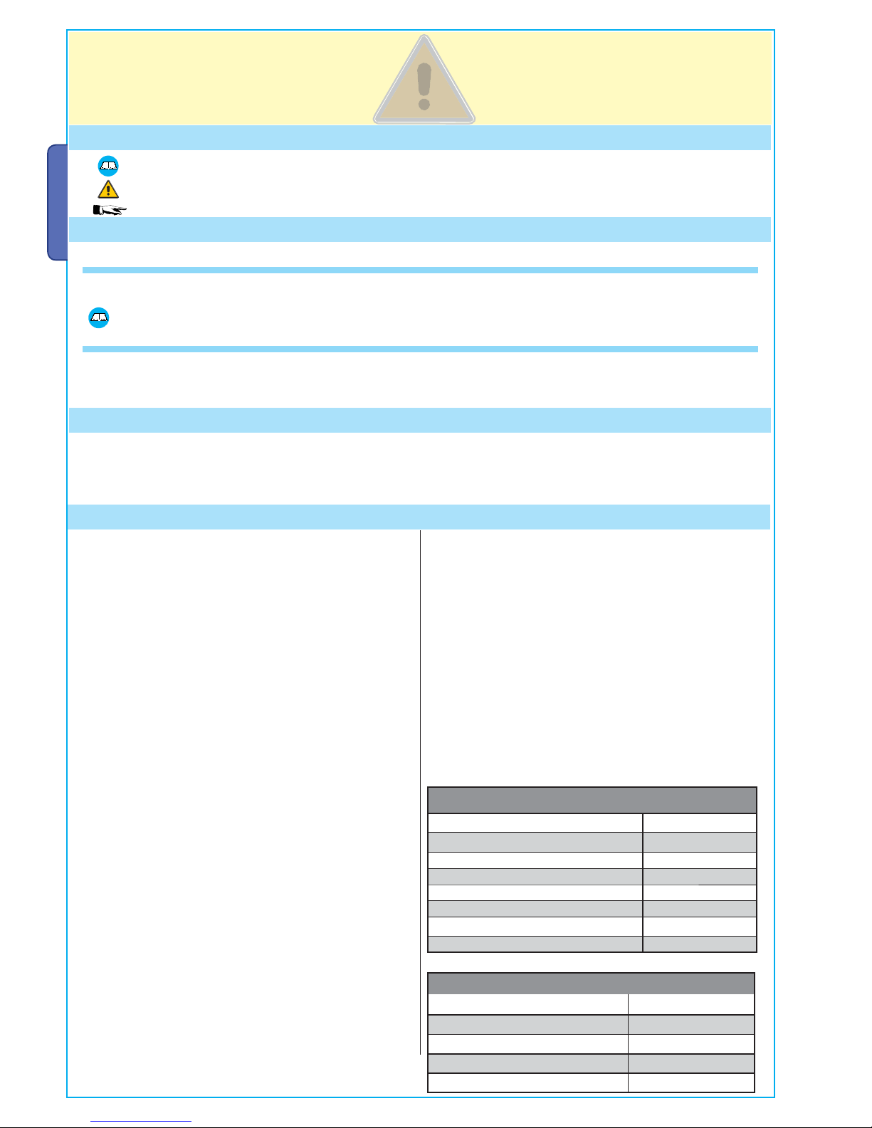
FUSES
protection: fuse type:
Motor/s 6.4 A-F
Electronic board (power supply line) 1.6 A-F
Accessories 2 A-F
Control devices 630 mA-F
TECHNICAL FEATURES
Power supply 230 V - 50/60 Hz
max. rated power 300 W
Power draw when idling 85 mA
Max power of 24 V accessories 34 W
Insulation rating II
Material ABS
Protection rating IP54
operating temperature -20 / +55°C
This product is engineered and manufactured by CAME cancelli
automatici s.p.a. and complies with current safety regulations.
Guaranteed 24 months if not tampered with.
The control panel works on 230 V AC of power, through the
term
inals L-N, 50/60 Hz frequency.
Both command and control devices and accessories are 24 V
po
wered. Warning! Accessories must not exceed 34 W overall.
The control unit is fi tted with an amperometric device which
constantly regulates the motor’s drive coeffi cient.
When the gate runs into an obstacle, the amperometric sensor
immediately detects an overcharge in the drive and redirects the
gate’s direction of movement, and:
- opens it if it is closing
(1)
;
- closes it if it is opening.
(1)
Warning!: in this case, after 3 consecutive obstacle detections, the gate
will stop open excluding the automatic closing function; for movement to
start again press the command button or use the remote control.
All connections are protected by quick fuses, see table.
The card provides and controls the following functions:
- automatic closing after an open-command;
- pre-fl ashing by the motion indicator;
- obstacle detection when gate is still in any position;
- continual monitoring of photocell operation.
The following command modes are possible:
- open/close;
- open/close and maintained action;
- partially open;
- complete stop;
- open/stop/close.
After detecting an obstacle and depending on the type of
connection used, the photocells may cause:
- reopening of the gate when it is closing;
- partial stop.
Apposite trimmers regulate:
- the automatic closing run time;
- the second gate leaf’s motion time difference;
- the amperometric device’s detection sensitivity, in separately
in terms of normal opening and closing and braking.
Further implemented options:
- controlling of just one gearmotor;
- peripheral speed reduction (for gate leaves of over 3 m);
- option to change opening endpoint fromt Stop to
Deceleration. With the function of slowing down is mandatory
setback mechanical;
- connecting up an electric lock (alternatively to the 2nd radio
channel or the “Open Gate” indicator light) and possibly adding
the “Ram Blow” function.
Make sure you respect the distances and cable diameters as shown in “cable types and minimal thicknesses” table.
The overall power of the motors must not exceed 300 W.
4 Description
2.1 - INTENDED USE
1 Legend of symbols
This symbol indicates sections to be read with particular care.
This symbol indicates sections concerning safety
This symbol indicates notes to communicate to users.
2 Intended use and application
3 Reference Standards
“IMPORTANT INSTALLATION, SAFETY INSTRUCTIONS”
“CAUTION: IMPROPER INSTALLATION MAY CAUSE SERIOUS DAMAGE, FOLLOW ALL INSTALLATION INSTRUCTIONS CAREFULLY”
“THIS MANUAL IS ONLY FOR PROFESSIONAL INSTALLERS OR QUALIFIED PERSONS”
2.2 - APPLICATION
For its quality processes management Came Cancelli Automatici is ISO 9001:2000 certified, and for its environmental management it
is
ISO 14001 certified. Came designs and manufactures entirely in Italy.
This product complies with the following standards: see chapter 13 - Conformity declaration - pag. 21.
A B C D E F G H I I
1
3
7 69
10
13
14
5
15
4
2
1211
8
A =
B =
C =
D =
E =
F =
G =
H =
I =
Pag.
3
3 -
Manual code
:
319U17
319U17
ver.
1.2
1.2
04/2010
9 © CAME cancelli automatici s.p.a. -
The data and information reported in this installation manual are susceptible to change at any time and without obligation on CAME cancelli automatici s.p.a. to notify users.
ENGLISH
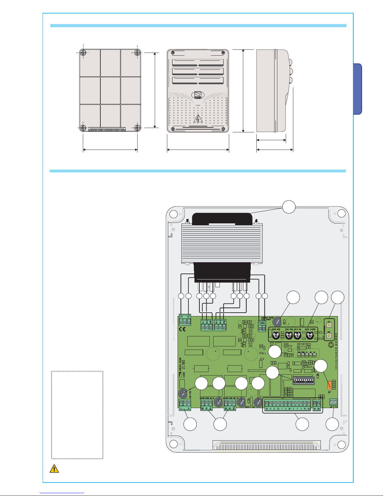
4.1 - DIMENSIONS, SPANS AND ANCHORING HOLES
4.2 - MAIN COMPONENTS
Warning! Before acting on the machinery, cut off the main power
supply and dis
connect any emergency batteries.
1 - Transformer
2
- Control unit fuse
3 - Trimmers (see page 9)
4 - Buttons for memorising the radio code
5 - Plug for the remote control frequency card
6 - Terminal board for connecting the antenna
7 - Terminal blocks for connecting accessories,
control and safety
8 - Terminal board for connecting the gearmotors
9 - Terminal board for 230 V AC power grid
10 - Line fuse
11 - M1 motor fuse
12 - M2 motor fuse
13 - Accessories fuse
14 - Fucntions selector
15 - Control and signalling LED unit
Black
White
Grey
Orange
Red
Blue
Brown
Yellow
Violet
LINKS
THE TRANSFORMER
295
215
!!
Pag.
4
4 - Manual code:
319U17
319U17 ver.
12
12 04/20109 © CAME cancelli automatici s.p.a. - The data and information reported in this installation manual are susceptible to change at any time and without obligation on CAME cancelli automatici s.p.a. to notify users.
ENGLISH
Before installing do the following:
• Check that the panel’s anchoring point is protected from possible blows, and that the anchoring surface is solid. Also check that the
anchoring is done using the appropriate bolts, screws etc.
• Make sure you have a suitable omnipolar cut-off device with contacts more than 3 mm apart, and independent (sectioned off) power
supply.
•
Make sure that any connections inside the case (that provide continuance to the protective circuit) are fitted with extra insulation
as compared to the other conductive parts inside;
• Make sure you have suitable tubing and conduits for the electrical cables to pass through and be protected against mechanical
damage.
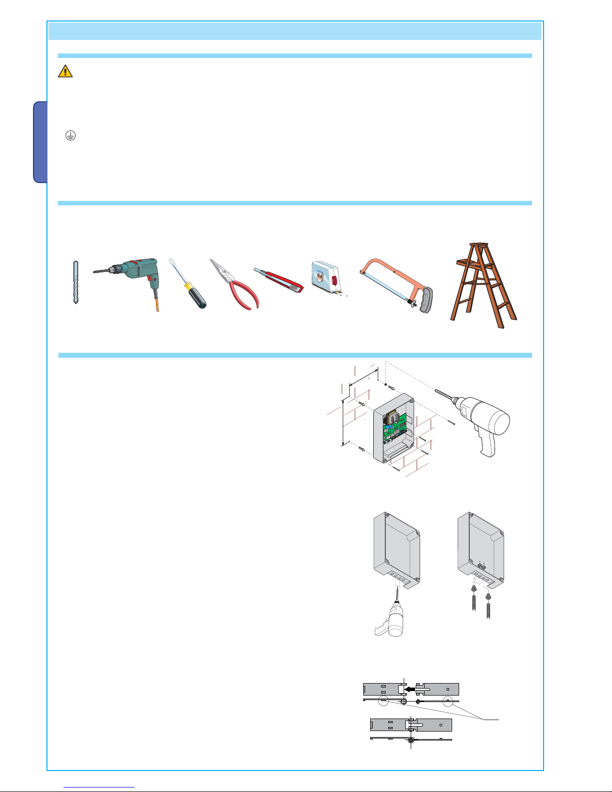
Make sure you have all the tools and materials you will need for the installation at hand to work in total safety and compliance with the
current standards and regulations. The following figure illustrates the minimum equipment needed by the installer.
Here are some examples.
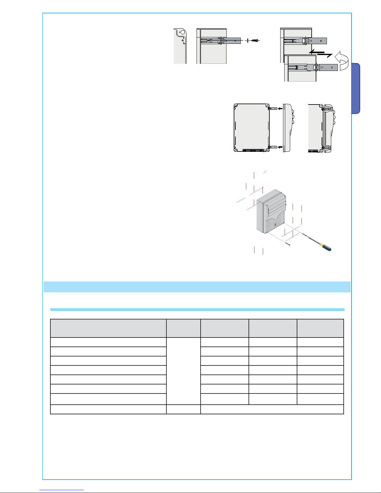
Fix the base of the panel in a protected area; we suggest
using round top Phillips recessed head screws of max. 6mm in
diameter.
5.3 - FIXING AND MOUNTING THE BOX
Perforate the pre-punched holes and insert the cable glands with
the corrugated tubing for the electrical cables to travel through
N.B.: the pre-punched holes have the following diameters:
23m 29 and 37 mm.
Assemble the pressure hinges.
5 Installation
5.1 - PRELIMINARY CHECKS
5.2 - TOOLS AND MATERIALS
15 mm~
Pag.
5
5 -
Manual code
:
319U17
319U17
ver.
1.2
1.2
04/2010
9 © CAME cancelli automatici s.p.a. -
The data and information reported in this installation manual are susceptible to change at any time and without obligation on CAME cancelli automatici s.p.a. to notify users.
ENGLISH
They must slide in order to turn
After the adjustments and settings, fix the cover using the provided
screws.
Insert the pressure hinges into the box (on the
left or right as you wish) and set them using the
provided screws and washers.
Snap the cover into place onto the hinges. Close it and fix it using the
provided screws.
6.1 - CABLE LIST AND MINIMUM THICKNESSES
N.B.: If the cable length differs from that specified in the table
, then you must determine the proper cable diameter based on the actual
power draw from the connected devices and according to the CEI EN 60204-1 standards.
For connections that require several, sequential loads, the sizes given on the table must be re-evaluated based on actual power draw
and distances.
When connecting products that are not specified in this manual, please follow the documentation provided with said products.
Connections
Type
of cable
Length of cable
1 < 10 m
Length of cable
10 < 20 m
Length of cable
20 < 30 m
Control panel power supply 230 V
FROR CEI
20-22
CEI EN
50267-2-1
3G x 1,5 mm
2
3G x 2,5 mm
2
3G x 4 mm
2
Motor power supply 24 V 3 x 1 mm
2
3 x 1,5 mm
2
3 x 2,5 mm
2
flashing lamp 2 x 0,5 mm
2
2 x 1 mm
2
2 x 1,5 mm
2
Transmitter photocells 2 x 0,5 mm
2
2 x 0.5 mm
2
2 x 0,5 mm
2
Receiver photocells 4 x 0,5 mm
2
4 x 0,5 mm
2
4 x 0,5 mm
2
Power supply to accessories 2 x 0,5 mm
2
2 x 0,5 mm
2
2 x 1 mm
2
Control and safety devices 2 x 0,5 mm
2
2 x 0,5 mm
2
2 x 0,5 mm
2
Antenna connection RG58 max. 10 m
6 Electrical connections
+
-
Pag.
6
6 - Manual code:
319U17
319U17 ver.
12
12 04/20109 © CAME cancelli automatici s.p.a. - The data and information reported in this installation manual are susceptible to change at any time and without obligation on CAME cancelli automatici s.p.a. to notify users.
ENGLISH
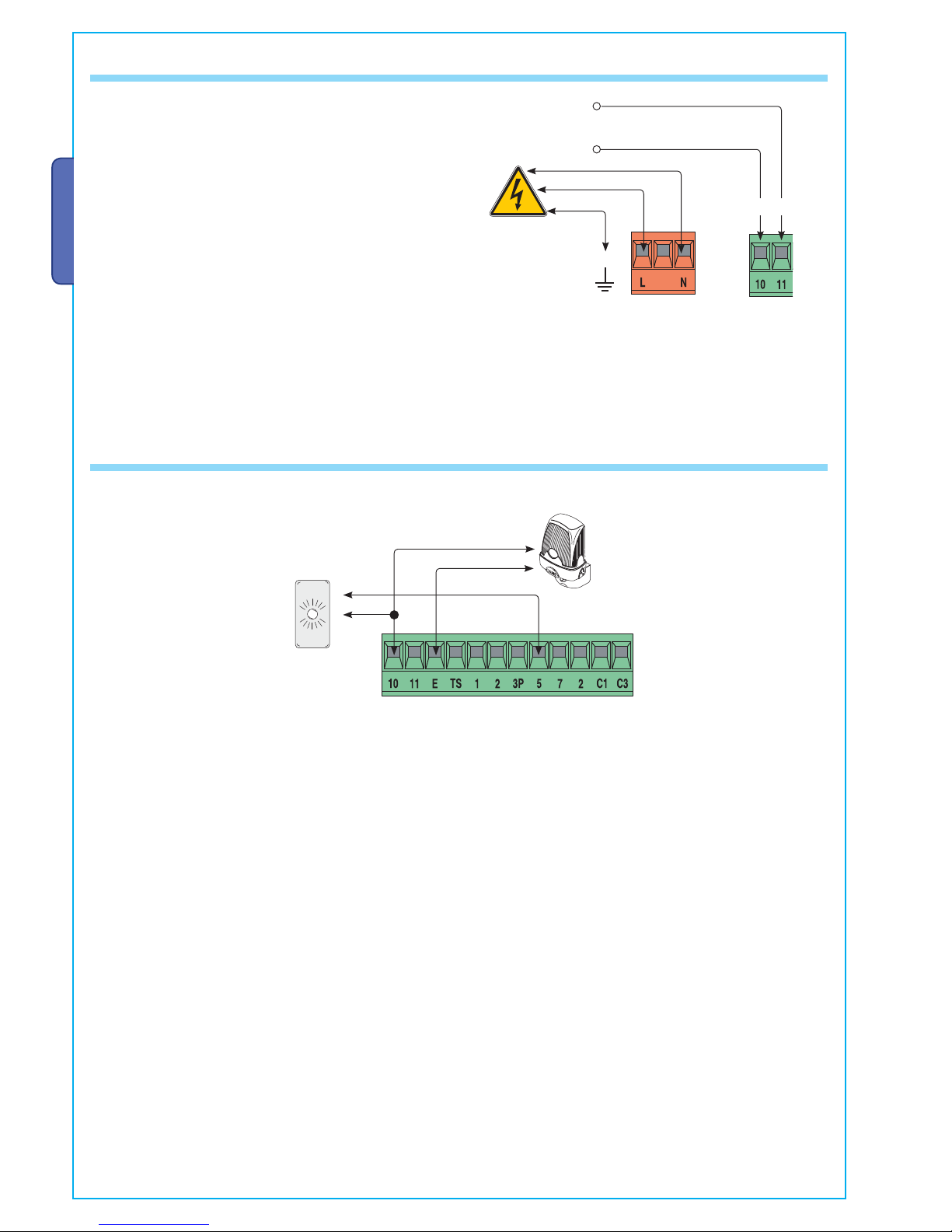
Terminals for powering the following accessories:
- 24 V AC (normally alternated power)
- 24 V AC (continuous power) when the emergency batteries
are in operation.
Overall power allowed: 34 W
Power supply
230 V AC 50/60 Hz
6.4 - POWER SUPPLY TO AND ACCESSORIES
6.3- SIGNALLING AND LIGHTING DEVICES
Open gate indicator-light
(socket rating: 24 V - 3 W max.).
- Turns on when the gate is ajar or
open. It turns off when the gate is
closed.
(Also see Chapt. 6.5)
Signal Flasher
(socket rating: 24 V - 25 W max.)
- Flashes during opening and
closing phases
Pag.
7
7 -
Manual code
:
319U17
319U17
ver.
1.2
1.2
04/2010
9 © CAME cancelli automatici s.p.a. -
The data and information reported in this installation manual are susceptible to change at any time and without obligation on CAME cancelli automatici s.p.a. to notify users.
ENGLISH
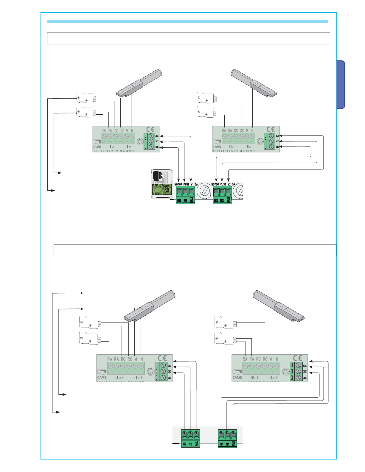
24V DC gearmotor
featuring delayed action on closing (M2),
Left-hand installed (inside view)
- Standard installation -
24V DC gearmotor
featuring delayed action on opening (M1),
Left-hand installed (inside view)
- Standard installation -
A302 4N-A5024N gearmotors
RA-RA = Opening-speed blocker
microswitch
RC-RC = Closing-speed reduction
microswitch
6.4 - CONNECTING TO THE GEARMOTORS
RA-RA = Microswitch
Opening programmable.
RC-RC = Closing-speed reduction
microswitch
A302 4N-A5024N gearmotors
24V DC gearmotor
featuring delayed action on closing (M2),
Left-hand installed (inside view)
- Standard installation -
24V DC gearmotor
featuring delayed action on opening (M1),
Left-hand installed (inside view)
- Standard installation -
LO
CK
UNLOCK
CAM
E
LOCK
UNLOCK
CAM
E
LO
CK
UNLOCK
CAM
E
LOCK
UNLOCK
CAM
E
Pag.
8
8 - Manual code:
319U17
319U17 ver.
12
12 04/20109 © CAME cancelli automatici s.p.a. - The data and information reported in this installation manual are susceptible to change at any time and without obligation on CAME cancelli automatici s.p.a. to notify users.
ENGLISH
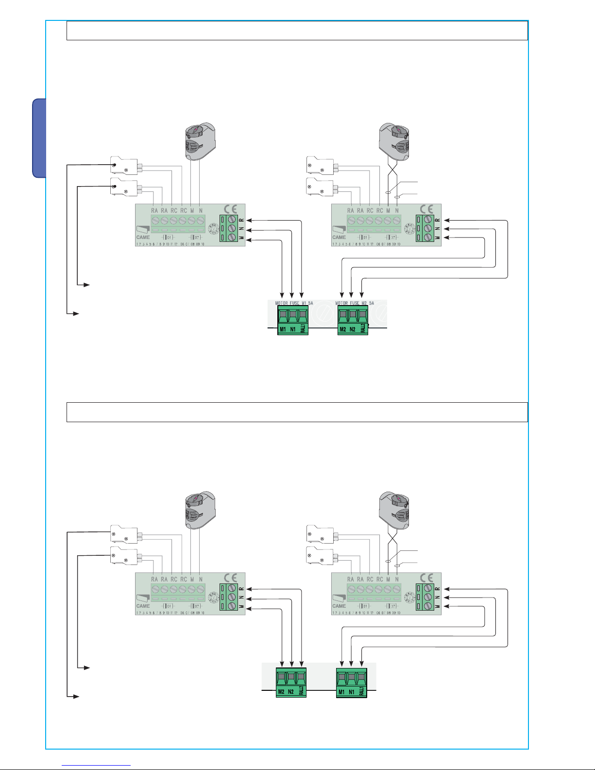
RC-RC = Closing-speed reduction
microswitch
M = red
N = b
lack
F7024N gearmotors
RA-RA = Microswitch
Opening programmable.
RA-RA = Opening-speed blocker
microswitch
RC-RC = Closing-speed reduction
microswitch
M = red
N = b
lack
F7024N gearmotors
24V DC gearmotor
featuring delayed action on closing
(M2),
Left-hand installed (inside view)
- Standard installation -
24V DC gearmotor
featuring delayed action on opening
(M1),
Left-hand installed (inside view)
- Standard installation -
24V DC gearmotor
featuring delayed action on closing
(M2),
Left-hand installed (inside view)
- Standard installation -
24V DC gearmotor
featuring delayed action on opening
(M1),
Left-hand installed (inside view)
- Standard installation -
 Loading...