

Page 1
CONTROL PANEL
h
ZL180 SERIES
FOR 24V OPERATORS
INSTALLATION MANUAL
ZL180
Englis
E
Page 2
2
319U17
12
“IMPORTANT INSTALLATION, SAFETY INSTRUCTIONS”
“CAUTION: IMPROPER INSTALLATION MAY CAUSE SERIOUS DAMAGE, FOLLOW ALL INSTALLATION INSTRUCTIONS CAREFULLY”
“THIS MANUAL IS ONLY FOR PROFESSIONAL INSTALLERS OR QUALIFIED PERSONS”
1 Legend of symbols
This symbol indicates sections to be read with particular care.
This symbol indicates sections concerning safety
This symbol indicates notes to communicate to users.
ENGLISH
2 Intended use and application
2.1 - INTENDED USE
The ZL180 control panel is designed to control the F7024N, A3024N and A5024N swing gate operators.
The use of this product for purposes other than as described above and installation executed in a manner other than
as instructed in this technical manual are prohibited.
2.2 - APPLICATION
Make sure you respect the distances and cable diameters as shown in “cable types and minimal thicknesses” table.
The overall power of the motors must not exceed 300 W.
3 Reference Standards
For its quality processes management Came Cancelli Automatici is ISO 9001:2000 certified, and for its environmental management it
ISO 14001 certified. Came designs and manufactures entirely in Italy.
This product complies with the following standards: see chapter 13 - Conformity declaration - pag. 21.
4 Description
This product is engineered and manufactured by CAME cancelli
automatici s.p.a. and complies with current safety regulations.
Guaranteed 24 months if not tampered with.
The control panel works on 230 V AC of power, through the
term
inals L-N, 50/60 Hz frequency.
Both command and control devices and accessories are 24 V
wered. Warning! Accessories must not exceed 34 W overall.
po
The control unit is fi tted with an amperometric device which
constantly regulates the motor’s drive coeffi cient.
When the gate runs into an obstacle, the amperometric sensor
immediately detects an overcharge in the drive and redirects the
gate’s direction of movement, and:
- opens it if it is closing
- closes it if it is opening.
(1)
Warning!: in this case, after 3 consecutive obstacle detections, the gate
will stop open excluding the automatic closing function; for movement to
start again press the command button or use the remote control.
(1)
;
All connections are protected by quick fuses, see table.
The card provides and controls the following functions:
- automatic closing after an open-command;
- pre-fl ashing by the motion indicator;
- obstacle detection when gate is still in any position;
- continual monitoring of photocell operation.
The following command modes are possible:
- open/close;
- open/close and maintained action;
- partially open;
- complete stop;
- open/stop/close.
After detecting an obstacle and depending on the type of
connection used, the photocells may cause:
- reopening of the gate when it is closing;
- partial stop.
Apposite trimmers regulate:
- the automatic closing run time;
- the second gate leaf’s motion time difference;
- the amperometric device’s detection sensitivity, in separately
in terms of normal opening and closing and braking.
Further implemented options:
- controlling of just one gearmotor;
- peripheral speed reduction (for gate leaves of over 3 m);
- option to change opening endpoint fromt Stop to
Deceleration. With the function of slowing down is mandatory
setback mechanical;
- connecting up an electric lock (alternatively to the 2nd radio
channel or the “Open Gate” indicator light) and possibly adding
the “Ram Blow” function.
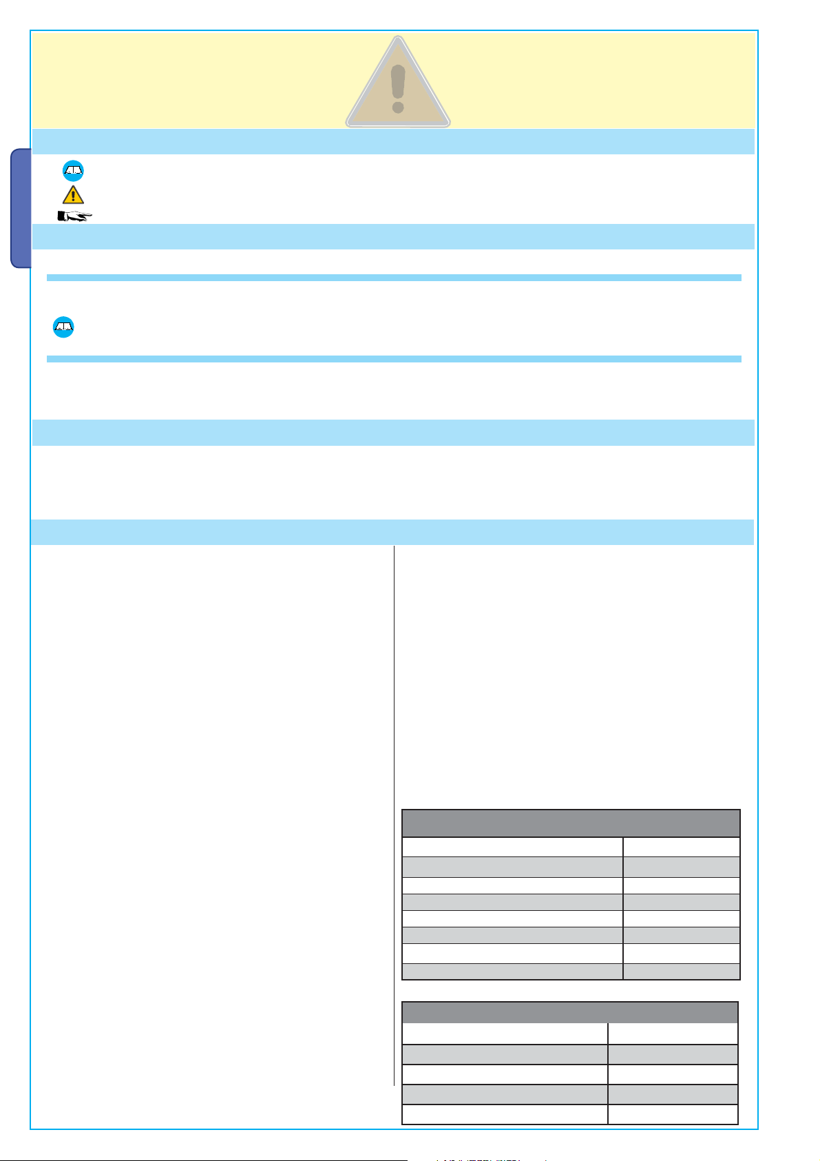
TECHNICAL FEATURES
Power supply 230 V - 50/60 Hz
max. rated power 300 W
Power draw when idling 85 mA
Max power of 24 V accessories 34 W
Insulation rating II
Material ABS
Protection rating IP54
operating temperature -20 / +55°C
FUSES
protection: fuse type:
Motor/s 6.4 A-F
Electronic board (power supply line) 1.6 A-F
Accessories 2 A-F
Control devices 630 mA-F
is
12 04/20109 © CAME cancelli automatici s.p.a. - The data and information reported in this installation manual are susceptible to change at any time and without obligation on CAME cancelli automatici s.p.a. to notify users.
319U17 ver.
2 - Manual code:
Pag.
Page 3
3
319U17
1.2
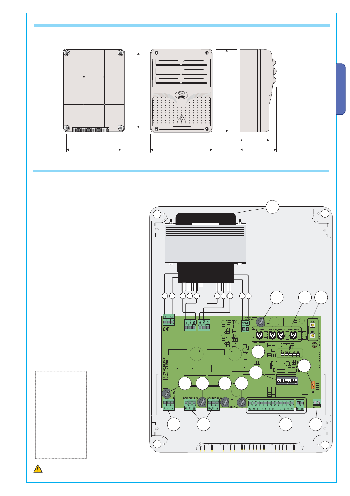
4.1 - DIMENSIONS, SPANS AND ANCHORING HOLES
4.2 - MAIN COMPONENTS
1 - Transformer
2
- Control unit fuse
3 - Trimmers (see page 9)
4 - Buttons for memorising the radio code
5 - Plug for the remote control frequency card
6 - Terminal board for connecting the antenna
7 - Terminal blocks for connecting accessories,
control and safety
8 - Terminal board for connecting the gearmotors
9 - Terminal board for 230 V AC power grid
10 - Line fuse
11 - M1 motor fuse
12 - M2 motor fuse
13 - Accessories fuse
14 - Fucntions selector
15 - Control and signalling LED unit
A B C D E F G H I I
ENGLISH
1
2
3
4
The data and information reported in this installation manual are susceptible to change at any time and without obligation on CAME cancelli automatici s.p.a. to notify users.
LINKS
THE TRANSFORMER
White
A =
9 © CAME cancelli automatici s.p.a. -
04/2010
1.2
ver.
319U17
:
Manual code
3 -
Pag.
Black
B =
Violet
C =
D =
Grey
Orange
E =
Red
F =
Blue
G =
Brown
H =
I =
Yellow
Warning! Before acting on the machinery, cut off the main power
supply and dis
connect any emergency batteries.
10
15
5
14
13
1211
8
7 69
Page 4
4
319U17
12
5 Installation
5.1 - PRELIMINARY CHECKS
Before installing do the following:
• Check that the panel’s anchoring point is protected from possible blows, and that the anchoring surface is solid. Also check that the
anchoring is done using the appropriate bolts, screws etc.
• Make sure you have a suitable omnipolar cut-off device with contacts more than 3 mm apart, and independent (sectioned off) power
supply.
•
Make sure that any connections inside the case (that provide continuance to the protective circuit) are fitted with extra insulation
as compared to the other conductive parts inside;
ENGLISH
• Make sure you have suitable tubing and conduits for the electrical cables to pass through and be protected against mechanical
damage.
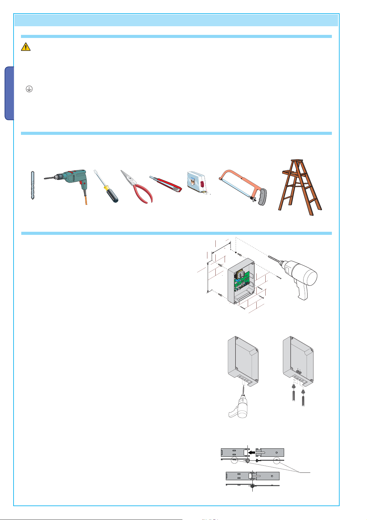
5.2 - TOOLS AND MATERIALS
Make sure you have all the tools and materials you will need for the installation at hand to work in total safety and compliance with the
current standards and regulations. The following figure illustrates the minimum equipment needed by the installer.
Here are some examples.
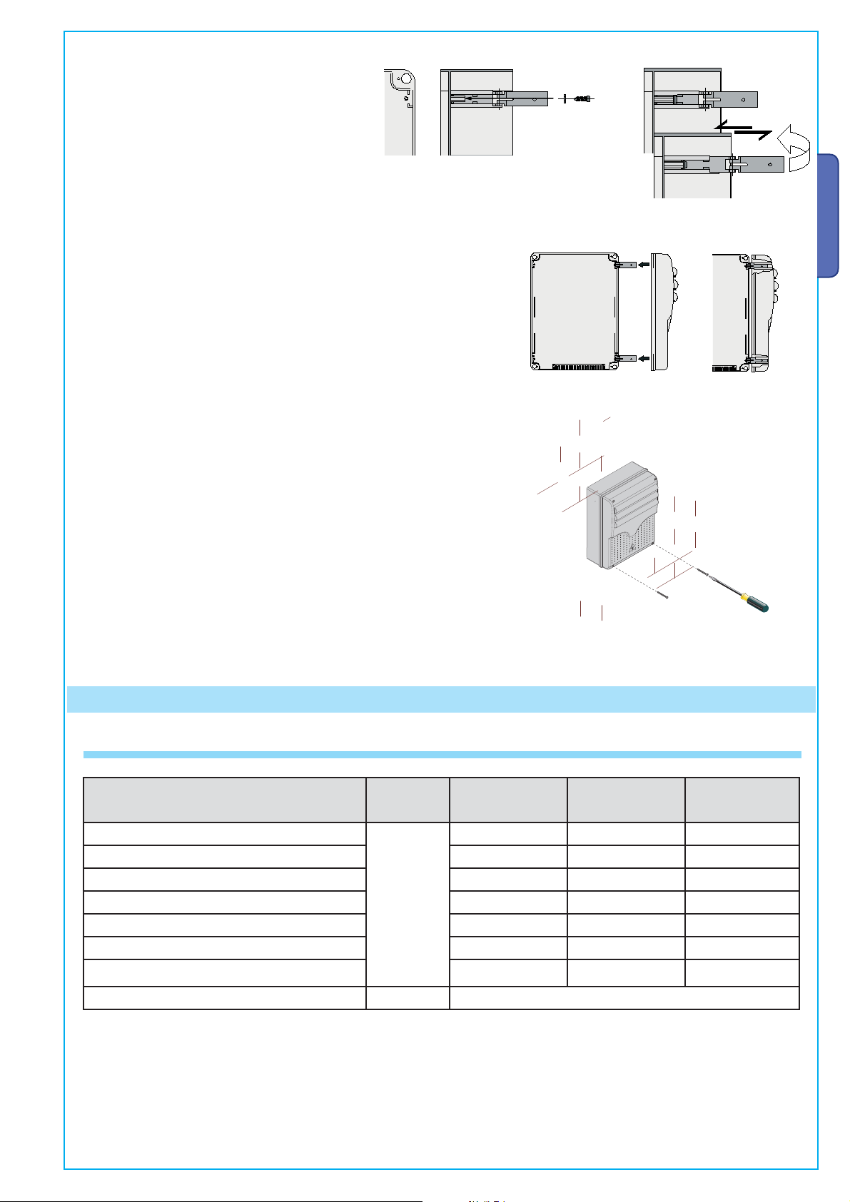
5.3 - FIXING AND MOUNTING THE BOX
Fix the base of the panel in a protected area; we suggest
using round top Phillips recessed head screws of max. 6mm in
diameter.
Perforate the pre-punched holes and insert the cable glands with
the corrugated tubing for the electrical cables to travel through
N.B.: the pre-punched holes have the following diameters:
23m 29 and 37 mm.
215
295
Assemble the pressure hinges.
!!
12 04/20109 © CAME cancelli automatici s.p.a. - The data and information reported in this installation manual are susceptible to change at any time and without obligation on CAME cancelli automatici s.p.a. to notify users.
319U17 ver.
4 - Manual code:
Pag.
Page 5
5
319U17
1.2
Insert the pressure hinges into the box (on the
left or right as you wish) and set them using the
provided screws and washers.
Snap the cover into place onto the hinges. Close it and fix it using the
provided screws.
15 mm~
They must slide in order to turn
ENGLISH
After the adjustments and settings, fix the cover using the provided
screws.
6 Electrical connections
6.1 - CABLE LIST AND MINIMUM THICKNESSES
Connections
The data and information reported in this installation manual are susceptible to change at any time and without obligation on CAME cancelli automatici s.p.a. to notify users.
Control panel power supply 230 V
Type
of cable
Motor power supply 24 V 3 x 1 mm
flashing lamp 2 x 0,5 mm
Transmitter photocells 2 x 0,5 mm
Receiver photocells 4 x 0,5 mm
FROR CEI
20-22
CEI EN
50267-2-1
Power supply to accessories 2 x 0,5 mm
9 © CAME cancelli automatici s.p.a. -
Control and safety devices 2 x 0,5 mm
Length of cable
1 < 10 m
3G x 1,5 mm
Length of cable
10 < 20 m
2
2
2
2
2
2
2
3G x 2,5 mm
3 x 1,5 mm
2 x 1 mm
2 x 0.5 mm
4 x 0,5 mm
2 x 0,5 mm
2 x 0,5 mm
2
2
2
2
2
2
2
Length of cable
20 < 30 m
3G x 4 mm
3 x 2,5 mm
2 x 1,5 mm
2 x 0,5 mm
4 x 0,5 mm
2 x 1 mm
2 x 0,5 mm
2
2
2
2
2
2
2
Antenna connection RG58 max. 10 m
04/2010
1.2
ver.
N.B.: If the cable length differs from that specified in the table
power draw from the connected devices and according to the CEI EN 60204-1 standards.
319U17
:
For connections that require several, sequential loads, the sizes given on the table must be re-evaluated based on actual power draw
, then you must determine the proper cable diameter based on the actual
and distances.
When connecting products that are not specified in this manual, please follow the documentation provided with said products.
Manual code
5 -
Pag.
Page 6
6
319U17
12
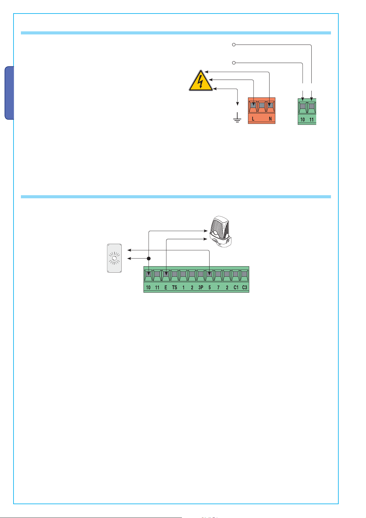
6.4 - POWER SUPPLY TO AND ACCESSORIES
Terminals for powering the following accessories:
- 24 V AC (normally alternated power)
- 24 V AC (continuous power) when the emergency batteries
are in operation.
Overall power allowed: 34 W
ENGLISH
Power supply
230 V AC 50/60 Hz
6.3- SIGNALLING AND LIGHTING DEVICES
+
-
Open gate indicator-light
(socket rating: 24 V - 3 W max.).
- Turns on when the gate is ajar or
open. It turns off when the gate is
closed.
(Also see Chapt. 6.5)
Signal Flasher
(socket rating: 24 V - 25 W max.)
- Flashes during opening and
closing phases
12 04/20109 © CAME cancelli automatici s.p.a. - The data and information reported in this installation manual are susceptible to change at any time and without obligation on CAME cancelli automatici s.p.a. to notify users.
319U17 ver.
6 - Manual code:
Pag.
Page 7
7
319U17
1.2
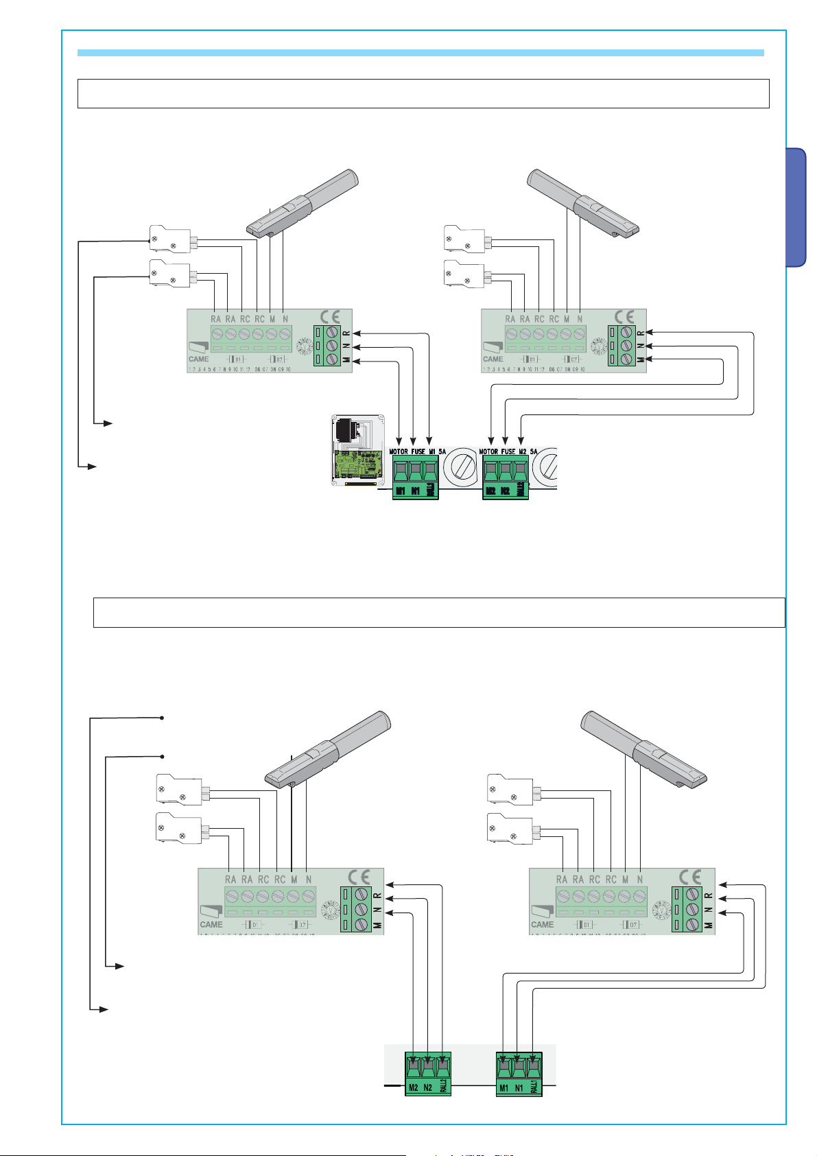
6.4 - CONNECTING TO THE GEARMOTORS
A302 4N-A5024N gearmotors
featuring delayed action on opening (M1),
24V DC gearmotor
Left-hand installed (inside view)
- Standard installation -
RA-RA = Opening-speed blocker
microswitch
RC-RC = Closing-speed reduction
microswitch
featuring delayed action on closing (M2),
24V DC gearmotor
Left-hand installed (inside view)
- Standard installation -
ENGLISH
The data and information reported in this installation manual are susceptible to change at any time and without obligation on CAME cancelli automatici s.p.a. to notify users.
9 © CAME cancelli automatici s.p.a. -
04/2010
1.2
ver.
319U17
:
featuring delayed action on closing (M2),
24V DC gearmotor
Left-hand installed (inside view)
- Standard installation -
RA-RA = Microswitch
Opening programmable.
RC-RC = Closing-speed reduction
microswitch
A302 4N-A5024N gearmotors
24V DC gearmotor
featuring delayed action on opening (M1),
Left-hand installed (inside view)
- Standard installation -
Manual code
7 -
Pag.
Page 8
8
319U17
12
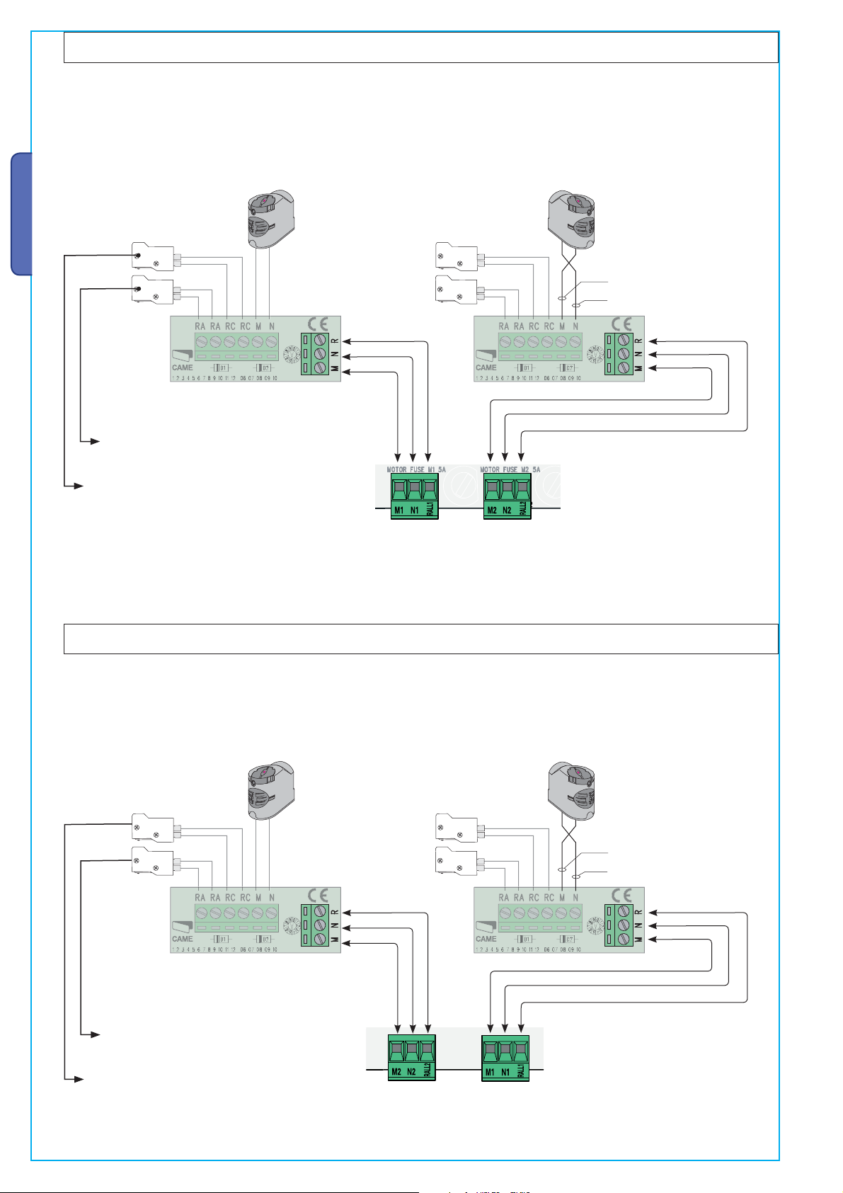
F7024N gearmotors
24V DC gearmotor
featuring delayed action on opening
(M1),
Left-hand installed (inside view)
- Standard installation -
ENGLISH
RA-RA = Opening-speed blocker
microswitch
RC-RC = Closing-speed reduction
microswitch
24V DC gearmotor
featuring delayed action on closing
E
CAM
UNLOCK
LOCK
E
CAM
UNLOCK
CK
LO
Left-hand installed (inside view)
(M2),
- Standard installation -
M = red
N = b
lack
featuring delayed action on closing
Left-hand installed (inside view)
RA-RA = Microswitch
Opening programmable.
F7024N gearmotors
24V DC gearmotor
(M2),
- Standard installation -
E
CAM
UNLOCK
LOCK
24V DC gearmotor
featuring delayed action on opening
(M1),
Left-hand installed (inside view)
- Standard installation -
E
CAM
UNLOCK
CK
LO
M = red
lack
N = b
12 04/20109 © CAME cancelli automatici s.p.a. - The data and information reported in this installation manual are susceptible to change at any time and without obligation on CAME cancelli automatici s.p.a. to notify users.
RC-RC = Closing-speed reduction
microswitch
319U17 ver.
8 - Manual code:
Pag.
Page 9

9
319U17
1.2
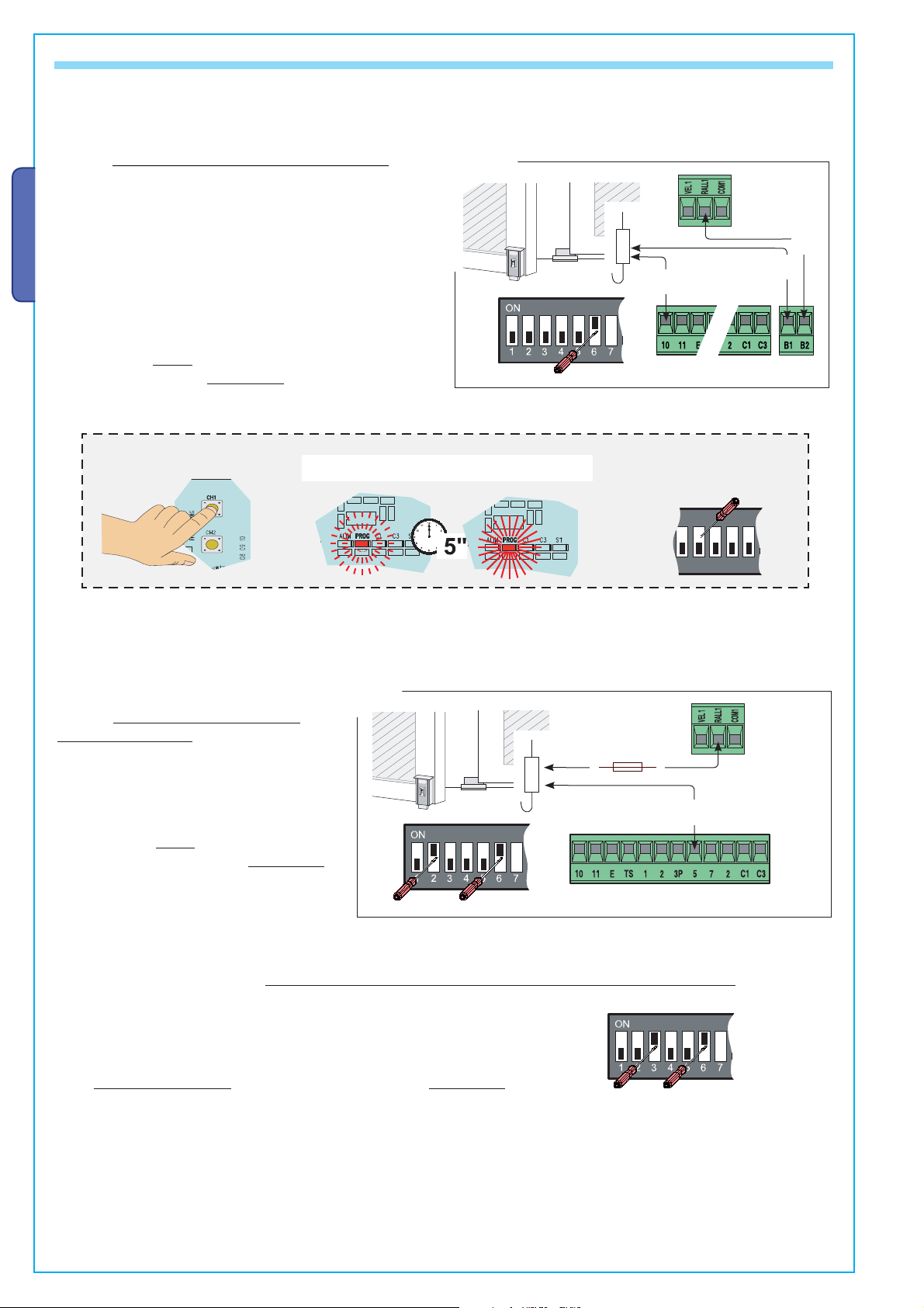
The ZL180 is calibrated to the F7024N or A3024N commands for gate leaves of up to 3 meters.
he following:
aa) - Set
dip switches 4 and 6 to ON
;
To command A5024N models (with gate leaves of over 3 m ) and reduce peripheral speed, do the
following:
a) - Set dip switches 1 and 6 to ON (and dip switches 2, 3, 4, 5 to OFF);
b) - press CH1: the red PROG led will start to blink;
c) - when the led stays on (after about 5 seconds) the procedure is complete;
d) - set to the dip switches back to OFF (or to the previous position, which depends on the
functions selection, see paragraph 7, page 12).
N.B.: to return to default, follow the same procedure while pressing CH2.
b) d)c) a)
CH1 = A5024N
default
CH2 = A3024N
F7024N
ENGLISH
The control panel is set for 2 gearmotors (2 leaved gates).
With only one gearmotor (one-leaved gates; M2 gearmotor), do t
) - Set
dip switches 4 and 6 to ON (and dip switches 1, 2, 3, 5 to OFF);;
he following:
CH1 = 1 gate leaf
b) - press CH1: the red PROG led will start to blink;
c) - when the led stays on (after about 5 seconds) the procedure is complete;
d) - set to the dip switches back to OFF (or to the previous position, which depends on the
functions selection, see paragraph 7, page 12).
default
CH2 = 2 gate leaves
N.B.: to return to default, follow the same procedure while pressing CH2.
b) d)c) a)
GEARMOTORS CONNECTION OPTIONS
The microswitches on RA terminals, set the opening stop by default.
CH2 = Opening slowdown
If you want instead the slowdown in opening is compulsory setback mechanics,
follow these steps:
The data and information reported in this installation manual are susceptible to change at any time and without obligation on CAME cancelli automatici s.p.a. to notify users.
a) - Set dip switches 5 and 6 to ON (and dip switches 1, 2, 3, 4 to OFF)
b) - press CH2: the red PROG led will start to blink;
;
c) - when the led stays on (after about 5 seconds) the procedure is complete;
d) - set to the dip switches back to OFF (or to the previous position, which
depends on the functions selection, see paragraph 7, page 12).
default CH1 = Opening stop
N.B.: to return to default, follow the same procedure while pressing CH1.
9 © CAME cancelli automatici s.p.a. -
04/2010
1.2
ver.
319U17
:
Manual code
9 -
Pag.
b) d)c) a)
Page 10
10
319U17
12
6.5- ELECTRICAL LOCK
aa) - Set
dip switches 2 and 6 to ON
;
bb),
),
) - continue with the above
COMMON
PROCEDUR
aa) - Set
dip switches 3 and 6 to ON
bb),
),
) - continue with the above
COMMON PROCEDUR
ZL180 lets you connect, in two different modes, a 12 V (15 Wmax) electrolock and, if necessary, also activate the “Ram Blow” function.
Mode 1 – Excludes use of the 2nd radio channel on B1-B2; after
connecting it, operate as follows:
a) - Set dip switc
h 6 to ON (and dip switches 1, 2, 3, 4, 5 to
OFF);;
Mode 1
RALL1
transformer
terminal
b) - press CH1: the red PROG led will start to blink;
c) - when the led stays on (after about 5 seconds) the
ENGLISH
procedure is complete;
d) - set to the dip switches back to OFF (or to the previous
position, which depends on the functions selection, see
a)
10
paragraph 7, page 12).
N.B.: to return to default (2nd radio channel on B1-B2), follow
the same procedure while pressing CH2.
COMMON PROCEDURE
b) d)c)
B2
B1
Mode 2 - Does not allow connection of an
Mode 2
indicator lamp on 10-5; after connection it:
) - Set
dip switches 2 and 6 to ON (and dip
switches 1, 3, 4, 5 to OFF)
), cc
), dd
) - continue with the above
PROCEDURE.
N.B.: to return to default (indicator lamp on 10-5),
;
COMMON
a)
follow the same procedure while pressing CH2.
In both modes, to activate the “ram blow”
) - Set
dip switches 3 and 6 to ON (and dip switches 1, 2, 4, 5 to OFF);;
), cc
), dd
) - continue with the above
(1)
:
COMMON PROCEDURE.
N.B.: to exclude the ram blow, follow the same procedure while pressing CH2.
(1)
Upon each opening command, the gate leaves press on the closing jamb for one second,
assisting the electrolock release operation.
place
a 3.15 A
fuse in between
a)
RALL1
transformer
terminal
5
12 04/20109 © CAME cancelli automatici s.p.a. - The data and information reported in this installation manual are susceptible to change at any time and without obligation on CAME cancelli automatici s.p.a. to notify users.
319U17 ver.
10 - Manual code:
Pag.
Page 11

11
319U17
1.2
6.6- SAFETY DEVICES
“Partial stop” (N.C.) socket
- input for safety devices such as photocells, sensitive
edges and other EN 12978-compliant devices. Halts
moving gate leaves and causes them to automatically
close
RX
DIR photocells
TX
ENGLISH
“Open during closing” (N.C.) socket
- Input for safety devices such as photocells, sensitive
edges and other EN 12978 compliant devices. When gate
leaves are closing, opening the contact causes reversal
until total opening is obtained.
“Partial Stop” (N.C.) socket
RX
DIR photocells
RX TX
./ # .#
DOC photocells
TX
The data and information reported in this installation manual are susceptible to change at any time and without obligation on CAME cancelli automatici s.p.a. to notify users.
“Open during closing” (N.C.) socket
9 © CAME cancelli automatici s.p.a. -
04/2010
1.2
ver.
319U17
:
Manual code
11 -
Pag.
RX
./ # .#
DOC photocells
TX
Page 12
12
319U17
12
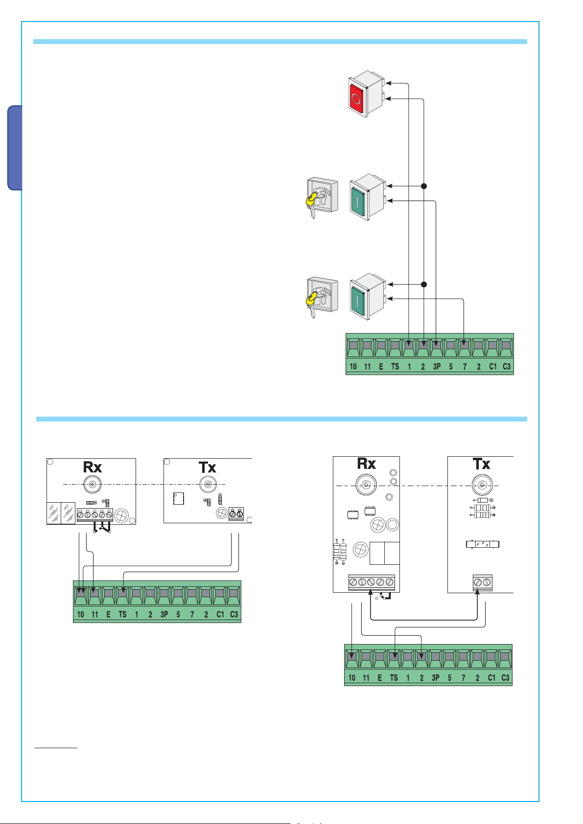
6.7- COMMAND DEVICES
Stop button (N.C. socket)
- Button to stop gate while excluding the automatic closing cycle.
For movement to resume you must press the command button or
transmitter button.
ENGLISH
Key selector and/or partial opening button (N.O. socket)
- Opening of one gate leaf to allow pedestrian passage.
Key selector and/or commands button (N.O. socket)
- Gate closing and opening contacts, by pressing the button or
turning the selector key, the gate movement is inverted or halted
depending on which selection was just made. (see selecting
functions, dips 2 and 3).
6.8- ELECTRICAL CONNECTION FOR THE PHOTOCELLS FUNCTIONS TEST
(DOC)
./
#
.#
(DIR)
48
&53)"),%M!
#
.#
48
48
At each opening and closing command, the control board assesses the
effi ciency status of the control devices (photocells). Any anomaly found
is signalled with the fl ashing of the (PROG) LED on the control panel.
Consequently it cancels any commands coming from the remote control or
the button.
Electrical connection to enable the photocell safety test:
- the transmitter and the receiver, must be connected as per the diagram;
- set DIP switch 9 to ON to activate test operation.
IMPORTANT:
when running the safety test function, the N.C. contacts, if unused, should be excluded on the relative DIP switches (see chapter 7
“selecting functions”).
12 04/20109 © CAME cancelli automatici s.p.a. - The data and information reported in this installation manual are susceptible to change at any time and without obligation on CAME cancelli automatici s.p.a. to notify users.
319U17 ver.
12 - Manual code:
Pag.
Page 13
13
319U17
1.2
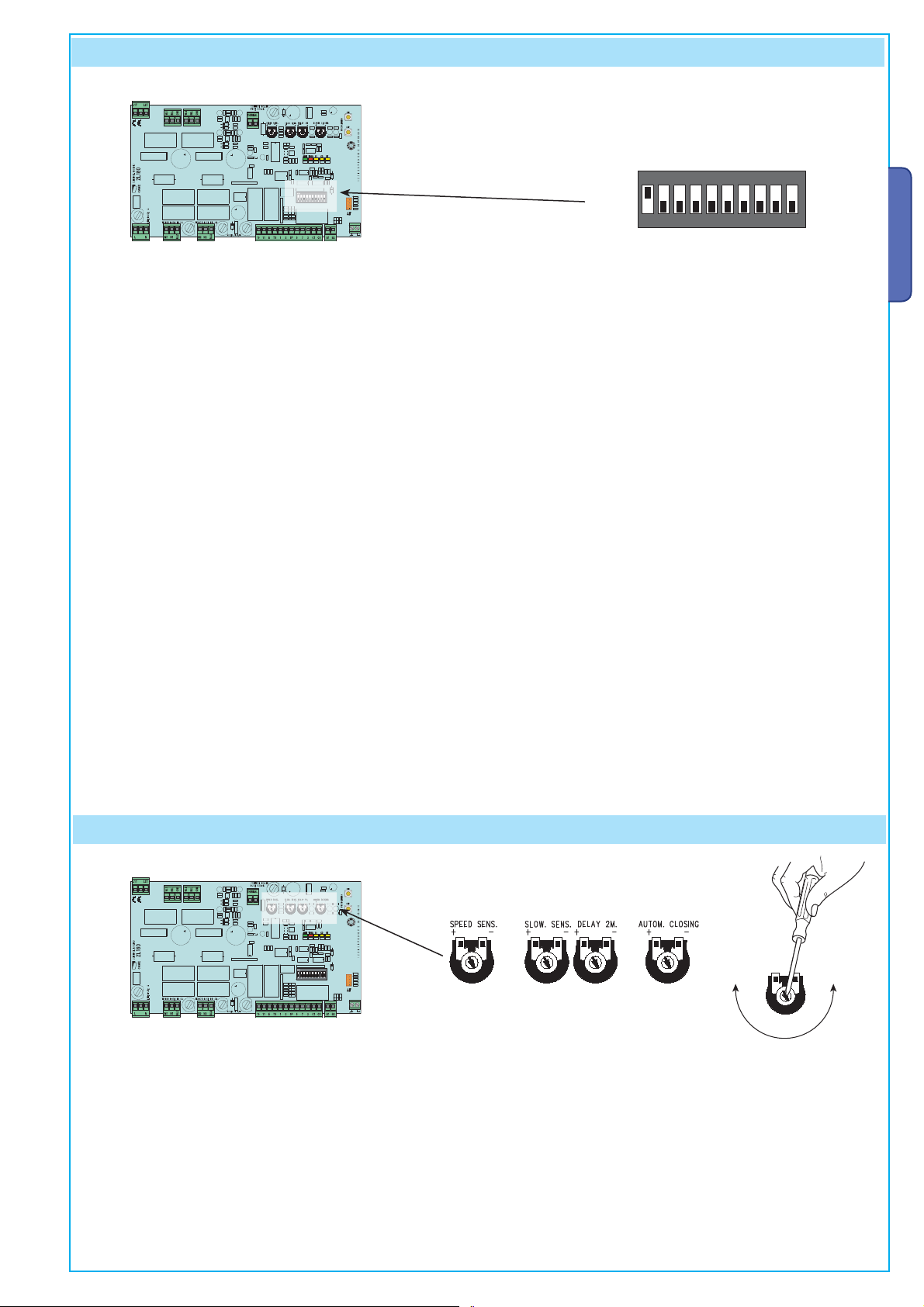
7 Selecting functions
DIP-SWITCH
/.
ON
OFF
1 ON - Automatic closing - the automatic closing timer is activated when on opening the gate leaf has reached the full open stroke.
The time is preset and adjustable, and is subject to the action of any safety devices. It does not activate after a total safety
“stop” or during a power outage;
2 ON - “Open-stop-close-stop” function with button [2-7] and remote control (with built-in radiofrequency card);
2 OFF - “Open-close” function with button [2-7] and remote control (with built-in radiofrequency card);
3 ON - “Open only” function with button [2-7] and remote control (with built-in radiofrequency card);
4 ON - Pre-Flashing during opening and closing - Following an opening or closing command, the flasher connected to [10-E],
lashes for 5 seconds before initiating the operation;
f
5 ON - Obstacle detection - When motor is idle (gate closed, open or after a total stop command), it prevents any motion if the
s
afety devices (e.g. photocells) detect any obstacle;
6 ON - Maintained action - the gate works by keeping the button pressed (one button [2-3P] for opening, and one button [2-7] for
closing);
7 OFF - Reopening during closing - if the photocells detect an obstacle during gate clo
sing, the gate motion is inverted until total
opening is reached; connect the safety device to terminals [2-C1); sif not used, set DIP switch to ON;
8 OFF - Partial stop - stops gate when an obstacle is detected by the safety devices; once the obstacle is cleared, the gate remains
still or closes if the automatic closing function is enabled. Connect the safety devices to terminal [2-C3); sif not used, set DIP
switch to ON.
9 ON - Operation of the photocells safety test - this allows the card to assess the efficiency of the safety devices (photocells) after
each open
ing and closing command;
10 ON - Reaction time - Increases to 2” the running time of the movement inversion function, controlled by the amperometric sensor
ENGLISH
.
NB – Dip switches 1 through 6 are used, independently, also for the gearmotor and electroloc connection options (pages 7-8-9).
8 Trimmers adjustment
The data and information reported in this installation manual are susceptible to change at any time and without obligation on CAME cancelli automatici s.p.a. to notify users.
9 © CAME cancelli automatici s.p.a. -
- «SPEED SENS.» Adjusts the amperometric sensitivity which controls the power developed by the motor during motion; if the
04/2010
- «SLOW.SENS.» Adjusts the amperometric sensitivity which controls the power developed by the motor during slowing downs; if
1.2
ver.
- «DELAY 2M» Adjustes the waiting time of the second motor during each closing run. The waiting time can be adjusted
319U17
:
- «AUTOM. CLOSING» Adjusts the waiting time when gate is open. Once this time has elapsed, the gate closes automatically. The
Manual code
13 -
Pag.
power exceeds the adjusted level, the system sets in motion to invert the direction of motion.
the power exceeds the adjusted level, the system sets in motion to invert the direction of motion.
anywhere between 1 and 17 seconds.
waiting time can be adjusted anywhere between 1 and 150 seconds.
Page 14
14
319U17
12
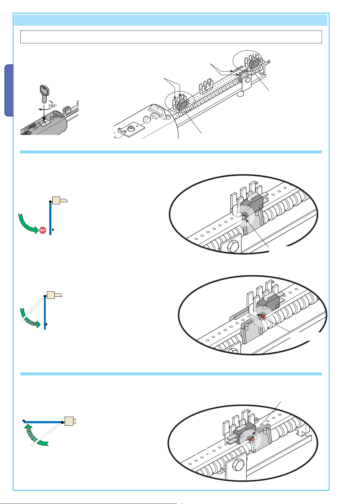
9 Adjusting the endstops
ATI gearm oto rs
Adjustments to carry out when
gearmotors are in release
mode: insert the release key
and turn it clockwise.
CAME
ENGLISH
locking/releasing the endstops
Screws for fi xing and
Microswitch
activating slide
Closing microswitch
Opening microswitch
- OPENING ENDSTOP - ATI gearmotors
Depending on the function you have assigned to the opening endstop (see paragraph 6.4, page 7) the adjustment settings will be
the following:
Opening Stop
(default function)
If it intervenes resulting in a Stop,
- manually push the door to the fully
opened position;
- release or detach the endstop
and slide it or reposition it
until the switch is activated
as shown in the drawing;
- lock the assembly in this
position.
Opening
deceleration
(option)
However, if it intervenes activating the Decelaration
mode,
- manually push the door to the fully
opened position;
- release or detach the endstop
and slide it or reposition it so
that the switch is adjacent
to the slide as shown in the
drawing;
- lock the assembly in this
position.
- CLOSING ENDSTOP - ATI gearmotors
The closing endstop only activates the deceleration.
Closing
deceleration
To adjust the microswitch,
- manually push the gate leaf to the fully
closed position;
- release or detach the endstop
and slide it or reposition it so
that the switch is adjacent
to the slide as shown in the
drawing;
- lock the assembly in this
position.
Switch
Switch
Switch
12 04/20109 © CAME cancelli automatici s.p.a. - The data and information reported in this installation manual are susceptible to change at any time and without obligation on CAME cancelli automatici s.p.a. to notify users.
319U17 ver.
14 - Manual code:
Pag.
Page 15

15
319U17
1.2
FAST gearmotors
WARNING! Make sure you have inverted the M-N connection for THE RIGHT-HAND MOTOR, as shown on page 8.
Adjustments to carry out when
gearmotors are released: insert
the release handle and turn it
counter-clockwise.
- SWITCHES OPENING - MOTOR LEFT (INSIDE VIEW)
Lower cam fi xing and
locking/release screw
Upper cam fi xing
and locking/release
screws
Lower cam
Upper cam
Closing microswitch
(above)
ENGLISH
ENDSTOP ASSEMBLY
Opening microswitch
(below)
Depending on the function you have assigned to the opening endstop (see paragraph 6.4, page 7) the adjustment settings will be the
following:
With the motor released, place the gate leaf at a distance
Rotate the lower cam clockwise until the microswitch is activated.
of 5 cm from the opening endstop.
The data and information reported in this installation manual are susceptible to change at any time and without obligation on CAME cancelli automatici s.p.a. to notify users.
Secure the cam using the central screw.
9 © CAME cancelli automatici s.p.a. -
04/2010
1.2
ver.
319U17
:
Manual code
15 -
Pag.
Page 16

16
319U17
12
CLOSING ENDSTOP – LEFTHAND GEARMOTOR (INSIDE VIEW)
N.B. The closing endstop can be adjusted after setting the opening microswitch.
Warning: the upper cam of the operator’s endstop assembly is calibrated for gate widths of between 1.2 m to 2.2 m.
- Release the gearmotor and fully close
the gate leaf.
ENGLISH
- Secure the cam by tightening the lateral
screws.
- turn the lower cam counter-clockwise, until the micro switch is
released.
LEFTHAND GEARMOTOR – INSIDE VIEW
If the gate leaf measures less than 1.2 m, you must turn the upper cam upside down and then set the microswitch.
- Remove the screws from the upper cam and turn it upsidedown.
- turn the lower cam counter-clockwise, until the micro switch is released.
Release the gearmotor and fully close the gate leaf.
- Secure the cam by tightening the lateral screws.
12 04/20109 © CAME cancelli automatici s.p.a. - The data and information reported in this installation manual are susceptible to change at any time and without obligation on CAME cancelli automatici s.p.a. to notify users.
319U17 ver.
16 - Manual code:
Pag.
Page 17

17
319U17
1.2
- OPENING ENDSTOP – RIGHTHAND GEARMOTOR – INSIDE VIEW
- Remove the screws from the upper cam and turn it upsidedown.
ENGLISH
- Release the motor and position the gate leaf 5
cm ajar from the opening endstop
- Secure the cam by tightening the central screw.
Turn the lo wer cam counter-clockwise, until the microswitch is engaged.
The data and information reported in this installation manual are susceptible to change at any time and without obligation on CAME cancelli automatici s.p.a. to notify users.
9 © CAME cancelli automatici s.p.a. -
04/2010
1.2
ver.
319U17
:
Manual code
17 -
Pag.
Page 18

18
319U17
12
CLOSING ENDSTOP – RIGHTHAND GEARMOTOR – INSIDE VIEW
N.B. Always fi rst adjust the opening endstop and then the closing endstop
Warning: the upper cam of the operator’s endstop assembly is calibrated for gate widths of between 1.2 m to 2.2 m.
- Release the gearmotor and fully close the
gate leaf.
ENGLISH
- Secure the cam by tightening the lateral screws.
- turn the upper cam clockwise, until the micro switch is released.
RIGHTHAND GEARMOTOR – INSIDE VIEW
If the gate leaf measures less than 1.2 m, you must turn the upper cam upside down and then set the microswitch.
- Remove the screws from the upper cam and turn it upsidedown. - Release the gearmotor and fully close the
gate leaf.
- turn the upper cam clockwise, until the micro-switch is released.
- Secure the cam by tightening the lateral screws.
12 04/20109 © CAME cancelli automatici s.p.a. - The data and information reported in this installation manual are susceptible to change at any time and without obligation on CAME cancelli automatici s.p.a. to notify users.
319U17 ver.
18 - Manual code:
Pag.
Page 19

19
319U17
1.2
10 Signal LED
LIST OF CONTROL LED SIGNALS OF THE COMMAND AND SAFETY DEVICES:
- «ALIM» Green LED. Normally on, because it signals the cards proper power rate.
- «PROG» Red LED. Normally off.
It blinks faster when combined with LEDs C1/C3/ST
- «C1» Yellow LED. Normally off.
- «C3» Yellow LED. Normally off.
- «ST» Yellow LED. Normally off.
During the remote control’s activation procedure, it turns on and blinks.
When it is on and with the PROG LED blinking it warns of objects detected by the photocells (connected to REOPEN
DURING CLOSING) or non-operation of the same.
When it is on and with the PROG LED blinking it warns of objects detected by the photocells (connected to PARTIAL STOP)
or non-operation of the same.
When it is on and with the PROG LED blinking it means the TOTAL STOP button has been pushed, or non-operation of the
same.
ENGLISH
11 Activating the remote control
11.1 - ANTENNA
Connect the antenna’s RG58 cable to
the apposite terminals.
The data and information reported in this installation manual are susceptible to change at any time and without obligation on CAME cancelli automatici s.p.a. to notify users.
11.2 - RADIOFREQUENCY CARD
Lock the radiofrequency card into the electronic card AFTER CUTTING
OFF
THE POWER SUPPLY (or after disconnecting the batteries).
N.B.: the electronic card only recognises the radiofrequency card
when the power is on.
9 © CAME cancelli automatici s.p.a. -
Possible output of the radio receiver’s
second channel (N.O. socket).
Socket rating: 5 A-24 V DC.
(Also see Chapt. 6.5)
AF card
04/2010
1.2
ver.
319U17
:
Manual code
19 -
Pag.
Page 20

CAME
CAME
CAME
CAME
CAME
CAME
CAME
CAME
CAME
CAME
CAME
CAME
20
319U17
12
11.3 - TRANSMITTERS
ENGLISH
ATOMO
AT01 • AT02
AT04
See instructions attached to AF43SR radiofrequency card
TOUCH
TCH 4024 • TCH 4048
TOP
TOP-432 A • TOP-434A
TAM
T432 • T434 • T438
TAM-432SA
CAME
CAME
See attached instructions
TOP
TOP-432NA • TOP-434NA
TOP-432S
TOP
TOP-302 A • TOP-304A
CAME
TFM
T132 • T134 • T138
T152 • T154 • T158
CAME
TWIN
TWIN2 • TWIN4
12 04/20109 © CAME cancelli automatici s.p.a. - The data and information reported in this installation manual are susceptible to change at any time and without obligation on CAME cancelli automatici s.p.a. to notify users.
319U17 ver.
20 - Manual code:
Pag.
Page 21

21
319U17
1.2
11.4 - MEMORISATION
CH1 = Channel for direct command to a function of the the gearmotor’s card, (“open only / “open-close-invert” or “open-stop-close-stop”
command, depending on the choice made on DIP switches 2 and 3).
CH2 = Channel for direct command an accessory device connected to B1-B2.
1) Keep the CH1 button on the electronic card pressed. The LED fl ashes.
CH1
LED flashing
ENGLISH
2) Press the transmitter button you wish to memorise. The LED will stay on to show memorisation has been successful.
3) Repeat the points 1 and 2 procedures for the “CH2” button associating this to another button on the transmitter.
The data and information reported in this installation manual are susceptible to change at any time and without obligation on CAME cancelli automatici s.p.a. to notify users.
T1
CH2
LE
D on
9 © CAME cancelli automatici s.p.a. -
04/2010
1.2
ver.
319U17
:
Manual code
21 -
Pag.
T2
Page 22

22
319U17
12
12 Phasing out and disposal
Our products are made with different types of materials. The majority of these (aluminium, plastic, iron and electrical cables) are
part of the solid urban waste category. They can be recycled through licensed waste disposal plants.
Other components (electronic cards, remote control batteries, etc.) constitute hazardous waste. Thus, they are to be removed and
delivered to licensed fi rms that specialise in their proper disposal.
ENGLISH
13 Conformity declaration
EC DECLARATION OF CONFORMITY
Pursuant to the Low Voltage Directive 2006/95/CE
CAME Cancelli Automatici S.p.A.
via Martiri della Libertà, 15
31030 Dosson di Casier - Treviso - ITALY
tel (+39) 0422 4940 - fax (+39) 0422 4941
internet: www.came.it - e-mail: info@came.it
Declares under its own responsibility that the equipments for automatic garage doors and gates listed below:
CONTROL PANELS FOR SWING GATES
ZL180
… comply with the National Law related to the following European Directives and to the applicable parts of the
following Standards.
2006/95/EC L
2004/108/EC ELECTROMAGNETIC COMPATIBILITY DIRECTIVE
OW VOLTAGE DIRECTIVE
Do not use the equipment specifi
in full compilance to the Low Voltage Directive 2006/95/CE
IMPORTANT WARNING!
ed here above, before completing the full installation
MANGING DIRECTOR
Mr. Gianni Michielan
EN 60335-1 EN 61000-6-2
EN 60335-2-103 EN 61000-6-3
EN 13241-1
Codice di riferimento per richiedere una copia conforme all’originale: DDF L EN Z002f
12 04/20109 © CAME cancelli automatici s.p.a. - The data and information reported in this installation manual are susceptible to change at any time and without obligation on CAME cancelli automatici s.p.a. to notify users.
319U17 ver.
22 - Manual code:
Pag.
Page 23

23
319U17
1.2
THIS PAGE LEFT INTENTIONALLY BLANK
THIS PAGE LEFT INTENTIONALLY BLANK
ENGLISH
The data and information reported in this installation manual are susceptible to change at any time and without obligation on CAME cancelli automatici s.p.a. to notify users.
9 © CAME cancelli automatici s.p.a. -
04/2010
1.2
ver.
319U17
:
Manual code
23 -
Pag.
Page 24

Englis h
319U17
1.2
CAME
France
S.a.
Nanterre Cedex
CAME Gmbh
Korntal
CAME Automatismes S.a.
Marseille
CAME Gmbh Seefeld
Seefeld
CAME Automatismos S.a.
Madrid
CAME Gulf Fze
Dubai
CAME United Kingdom Ltd.
Nottingham
CAME Rus
Umc Rus Llc
Moscow
CAME Group Benelux S.a.
Lessines
CAME (Shanghai)
Automatic Gates Co. Ltd.
Shanghai
CAME Americas Automation Llc
Medley
CAME Portugal
Ucj Portugal Unipessoal Lda
Porto
CAME Cancelli Automatici S.p.a.
Dosson Di Casier
CAME Sud s.r.l.
Napoli
CAME Ser vice Italia S.r.l.
Dosson Di Casier
Assistenza Tecnica 800 295830
www.came.com www.came.it
08_2009
CAME
France
S.a. FRANCE
7, Rue Des Haras
Z.i. Des Hautes Patures
Nanterre Cedex
92737
(+33) 1 46 13 05 05
GERMANY
CAME Gmbh
Kornwestheimer Str. 37
Korntal Munchingen Bei Stuttgart
70825
(+49) 71 5037830
(+49) 71 50378383
(+33) 1 46 13 05 00
CAME Automatismes S.a. FRANCE
3, Rue Odette Jasse
13015
Marseille
(+33) 4 95 06 33 70
(+33) 4 91 60 69 05
CAME Automatismos S.a. SPAIN
C/juan De Mariana, N. 17-local
28045
Madrid
(+34) 91 52 85 009
(+34) 91 46 85 442
GERMANY
CAME Gmbh Seefeld
Akazienstrasse, 9
16356
Seefeld Bei Berlin
(+49) 33 3988390
(+49) 33 39883985
CAME Gulf Fze
U.A.E.
Offi ce No: S10122a2o210
P.O. Box 262853
Jebel Ali Free Zone -
(+971) 4 8860046
Dubai
(+971) 4 8860048
CAME United Kingdom Ltd. GREAT BRITAIN
Unit 3 Orchard Business Park
Town Street, Sandiacre
Nottingham - Ng10 5bp
(+44) 115 9210430
(+44) 115 9210431
CAME Rus
RUSSIA
Ul. Otradnaya D. 2b, Str. 2, offi ce 219
127273,
(+7) 495 739 00 69
(+7) 495 739 00 69 (ext. 226)
Umc Rus Llc
Moscow
1.2 04/2010 © CAME cancelli automatici s.p.a.
319U17 ver.
The data and information reported in this installation manual are susceptible to change at any time and without obligation on CAME cancelli automatici s.p.a. to notify users.
English - Manual code:
CAME Group Benelux S.a. BELGIUM
Zoning Ouest 7
7860
Lessines
(+32) 68 333014
(+32) 68 338019
CAME Americas Automation Llc U.S.A
11405 NW 122nd St.
Medley, FL 33178
(+1) 305 433 3307
(+1) 305 396 3331
CAME Cancelli Automatici S.p.a. ITALY
Via Martiri Della Libertà, 15
31030
Dosson Di Casier (Tv)
(+39) 0422 4940
(+39) 0422 4941
Informazioni Commerciali 800 848095
CAME (Shanghai)
CHINA
Automatic Gates Co. Ltd.
1st Floor, Bldg 2, No. 1755, South Hongmei Road
Shanghai 200237
(+86) 021 61255005
(+86) 021 61255007
PORTUGAL
CAME Portugal
Ucj Portugal Unipessoal Lda
Rua Jùlio Dinis, N. 825, 2esq
4050 327
(+351) 915 371 396
ITALY
CAME Sud s.r.l.
Via F. Imparato, 198
Centro Mercato 2, Lotto A/7
80146
(+39) 081 7524455
(+39) 081 7529190
Porto
Napoli
CAME Service Italia S.r.l. ITALY
Via Della Pace, 28
31030
Dosson Di Casier (Tv)
(+39) 0422 383532
(+39) 0422 490044
Assistenza Tecnica 800 295830
 Loading...