

Page 1
SERIE Z |
Z
SERIES
| SÉRIE Z |
BAUREIHE
Z |
SERIE Z
Documentazione
Tecnica
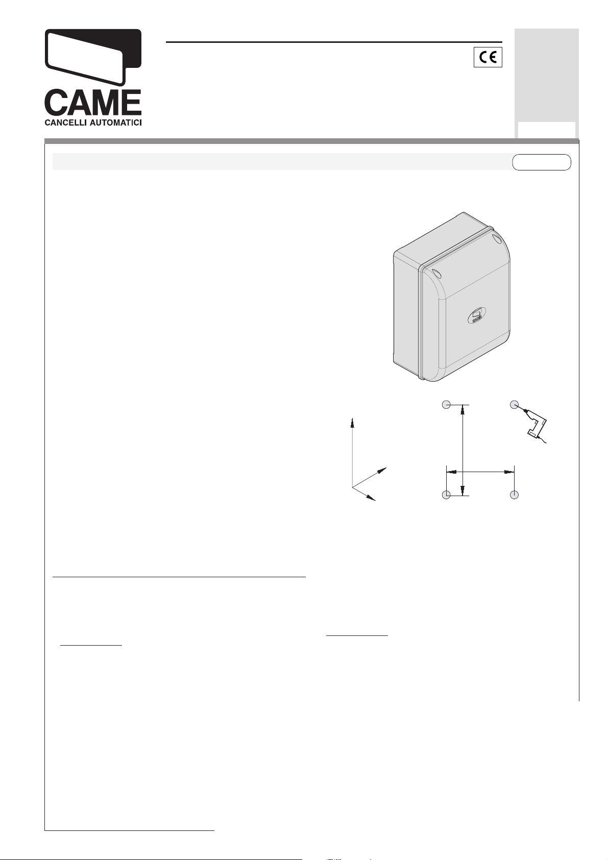
QUADRO COMANDO
CONTROL PANEL
ARMOIRE DE COMMANDE
SCHALTTAFEL
CUADRO DE MANDO
CARATTERISTICHE GENERALI
Descrizione
Il quadro comando ZL160N è adatto al comando
di 1 automazione a 24V della serie FLEX
con potenza fino a 48W.
Progettato e costruito interamente dalla CAME
S.p.A., risponde alle vigenti norme di sicurezza
con grado di protezione IP54. Contenitore in
ABS.
Garantito 24 mesi salvo manomissioni.
Il quadro deve essere alimentato a 230V (a.c.)
sui morsetti L1 e L2, ed é protetta in ingresso
con fusibile da 1.6A, mentre i dispositivi di
comando a bassa tensione (24V) sono protetti
con fusibile da 3.15A.
ZL160N
274
U38
rev. 0.1
12/2006
©
CAME
CANCELLI
AUTOMATICI
319U38
ITALIANOITALIANO
ITALIANO
ITALIANOITALIANO
La potenza complessiva degli accessori (24V)
non deve superare i 40W.
Il quadro include un sensore amperometrico,
che controlla costantemente la forza sviluppata
dal motore in apertura o in chiusura: se questa
supera il livello preimpostato (per esempio, nel
caso ci sia un ostacolo che blocca il movimento), entra in funzione arrestando il motore.
Sicurezza
Le fotocellule possono essere collegate e predisposte per:
-
Riapertura
in fase di chiusura (2-C1), le fotocellule rilevando un ostacolo durante la fase di
chiusura del cancello, provocano l'inversione di
marcia fino alla completa apertura;
254
204
184
133
Stop totale
l'esclusione del ciclo di chiusura automatica,
per riprendere il movimento del cancello, agire
sulla pulsantiera o sul radiocomando;
(1-2), arresto del cancello con
Page 2
Accessori opzionali
-
Elettroserratura
-
Lampada spia cancello aperto
12V (2-ES);
(3W max.).
Lampada che segnala la posizione di apertura
del cancello, si spegne quando il cancello è in
posizione di chiusura (10-5).
Scheda LB54
-
. Alimenta i motoriduttori tramite
batterie nel caso di mancanza di energia elettrica. Al ripristino della linea esegue anche la loro
ricarica.
Altre funzioni
-
Chiusura automatica.
Il temporizzatore di chiusura automatica si autoalimenta a finecorsa in
apertura. Il tempo prefissato regolabile, è in
ogni modo subordinato dall'intervento di eventuali accessori di sicurezza e si esclude dopo un
intervento di "stop" o in mancanza d'energia
elettrica;
"azione mantenuta"
-
. Funzionamento del cancello mantenendo premuto il pulsante (esclude
la funzione del radiocomando). Si abilita quando il trimmer T.L. è regolato al minimo.
Colpo d’ariete.
-
Ad ogni comando di apertura,
l’anta preme in battuta di chiusura per un secondo, facilitando l’operazione di sgancio
dell’elettroserratura collegata sui morsetti 2-ES.
É attivo solo se l’anta è chiusa a fine tempo
lavoro.
Regolazioni
- Tempo chiusura automatica;
- Tempo lavoro.
Attenzione! Prima di intervenire all’interno dell’apparecchiatura, togliere la
tensione di linea.
-2-
Page 3
GENERAL CHARACTERISTICS
ENGLISHENGLISH
ENGLISH
ENGLISHENGLISH
Description
The ZL160N control panel is suitable for controlling an automatic system for the FLEX series swing gates powered by 24V d.c. with capacity up to 48W.
Designed and built entirely by CAME S.p.A. to
meet safety standards at an IP 54 protection
level. Housing in ABS.
Guaranteed 24 months, unless tampered with.
The circuit requires 230V (AC) on terminal blocks
L1 and L2, and is protected with 1.6A fuse,
whilst the low voltage command devices are
protected by a 3,15A fuse.
The accessories total capacity (24V) should not
exceed 40W.
The control panel includes an amperometric
sensor that constantly checks the force developed by the motor when opening or closing: if
this exceeds the preset level (for example, in
the event of an obstacle blocking movement), it
becomes operative and stops the motor.
- LB54 Board
. Powers the reduction gears
through batteries in case of a power outage.
After the power supply is restored, it also recharges the batteries.
Other functions
-
Automatic closing.
The automatic closing timer
is automatically activated at the end of the
opening cycle. The preset, adjustable automatic closing time is automatically interrupted
by the activation of any safety system, and is
deactivated after a STOP command or in case
of power failure;
"
Maintained action". Gate operates only when
the pushbutton is held down (the radio remote
control system is deactivated). It is activated
when the T.L. trimmer is set to the minimum;
- Hammer move-
ment.
At every opening command, the wings
press the closing stop-ledge for a second, thus
facilitating the release operation of the electric
lock connected to terminals 2-ES.
Safety
Photocells can be connected to abtain:
-
Re-opening
during closure (2-C1), if the photocells identify an obstacle while the gate is
closing, they will reverse the direction of movement until the gate is completely open;
Total stop
-
(1-2), shutdown of gate movement
without automatic closing, a pushbutton or radio
remote control must be actuated to resume
movement.
Optional accessories
-
12V
Electric lock
Gate open pilot lamp
-
(2-ES);
(3W max.). A lamp that
signals the gate’s open position and that goes
out when the gate is in the closed position.
Connected to terminals 10-5;
It is only active if the wings are closed and at
the end of the work time.
Adjiustments
- Automatic closure time;
- Operating time.
Important! Disconnect the unit from the
main power lines before carrying out any
operation inside the unit.
-3-
Page 4
CARACTÉRISTIQUES GÉNÉRALES
Description
Le tableau de commande ZL160N sert à commander les automatismes pour portails à battant de la série FLEX alimentés à 24V c.c. avec
puissance jusqu’à 48W.
Conçue et construite entièrement par CAME
S.p.A., elle est conforme aux normes en vigueur.
Boîtier en ABS avec degré de protection IP54.
Garantie 24 mois sauf en cas d’endommagement.
Le circuit doit être alimentée avec une tension
de 230V (c.a.) aux bornes L1 et L2, et est
protégée à l’entrée par fusible de ligne 1.6A,
tandis que les dispositifs de commande à basse
tension (24V) sont protégés par un fusible de
3,15A.
La puissance total des accessoires (24V) ne
doit pas dépasser 40W.
Le tableau est équipé d’un capteur
ampèremétrique qui contrôle constamment la
force développée par le moteur en ouverture ou
en fermeture: il intervient en arrêtant le moteur
si celle-ci dépasse le niveau préétabli (par exemple au cas où un obstacle bloquerait le mouvement).
Sécurité
Il est possible de brancher des photocellules et
de les programmer pour:
-
Réouverture
en phase de fermeture (2-C1),
les cellules photoélectriques provoquent l'inversion de marche jusqu'à l'ouverture complète
si elles relèvent un obstacle durant la phase de
fermeture du portail;
FRANÇAISFRANÇAIS
FRANÇAIS
FRANÇAISFRANÇAIS
Accessoires en option
-
Serrure électrique
-
Lampe témoin portail ouvert
12V (2-ES);
(3W max.).
Lampe qui signale la position d’ouverture du
portail et s’éteint quand le portail est en position de fermeture. Elle est branchée sur les bornes 10-5.
- Carte LB54
. Elle alimente les motoréducteurs
à l’aide de batteries en cas de coupure de courant. Elle recharge également les batteries
quand le courant est rétabli.
Autres fonctions
-
Fermeture automatique.
Le temporisateur de
fermeture automatique est autoalimenté à la fin
du temps de la course en ouverture. Le temps
réglable est programmé, cependant, il est subordonné à l’intervention d’éventuels accessoires de sécurité et il est exclu après une intervention de “stop” ou en cas de coupure de courant;
Fonction “ouverture seulement
-
”.
Fonctionnement du portail en maintenant
appuyé le bouton-poussoir (exclut la fonction
de la radiocommande). Il s’active quand le
compensateur T.L. est réglé au minimum;
-
Coup de bélier.
Les vantaux appuient contre
la butée de fermeture pendant une seconde à
chaque commande d’ouverture en facilitant
l’opération de déclenchement de la serrure électrique branchée aux bornes 2-ES.
Il n’est activé qu’à la fin du temps de travail et
si les vantaux sont fermés.
Stop total
-
(1-2), arrêt du portail et désactivation d’un éventuel cycle de fermeture automatique; pour activer de nouveau le mouvement, il
faut agir sur les boutons-poussoirs ou sur la
radiocommande.
-4-
Réglages
- Temps de fermeture automatique;
- Temps de fonctionnement.
Attention! Avant d’intervenir à l’intérieur
de l’appareillage, couper la tension de
ligne.
Page 5
ALLGEMEINE MERKMALE
DEUTSCHDEUTSCH
DEUTSCH
DEUTSCHDEUTSCH
Beschreibung
Die Schalttafel ZL160N eignet sich zur Steuerung von Automatiksystemen für Flügeltore der
Serie FLEX mit einer Versorgungsspannung von
24 V DC, einer Leistung von max. 48 W.
Entwurf und Konstruktion sind von der CAME
CANCELLI AUTOMATICI S.p.A.; sie entspricht
den geltenden Sicherheitsnormen. Der Kasten
ist in ABS, Schutzgrad IP54. 24 Monate Garantie, vorbehaltlich unsachgemäßer Handhabung
und Montage.
Die Versorgung des Stromkreíses erfolgt mit
230V (Wechselstrom) über die Klemmen L1-L2
und ist am Eintritt durch 1.6A-Sicherungen geschützt. Die Steuervorrichtungen funktionieren
mit Unterspannung (24V) und sind durch eine
3,15A-Sicherung geschützt.
Die Gesamtleistung der Zubehörteile (24V) darf
40W nicht übersteigen.
Zur Steuerung gehört ein Sensor zur Strommessung, der eine konstante Kontrolle der vom
Motor beim Öffnen und Schließen entwickelten
Kraft durchführt. Sollte die Kraft den vorgegebenen Schwellenwert übersteigen - z.B. wenn
die Bewegung durch ein Hindernis blockiert wird
- schaltet sich der Sensor zu und löst das Abschalten des Motors aus.
Sicherheitsvorrichtungen
Die Lichtschranken können für folgende Funktionen angeschlossen bzw. vorbereitet werden:
Wiederöffnen
-
beim Schließen (2-C1), die
Lichtschranken ermitteln ein Hindernis während
des schließens vom Tor und lösen die Umkehr
der Laufrichtung vom Tor aus, bis dieses wieder
vollständig geöffnet ist;
Totalstop
-
(1-2), sofortiger Stillstand des Tores
mit Ausschluß eventueller Schließautomatik:
Fortsetzung des Torlaufs über Drucktaster- bzw.
Funksendersteuerung;
Extrazubehör
-
Elektroschloß
- Kontrolllampe Tor offen
12V (2-ES);
(3W max.). Zeigt an,
daß das Tor offen ist und geht aus, wenn das
Tor wieder geschlossen ist. Wird an die Klemmen 10-5 angeschlossen.
Karte LB54
. Versorgt die Getriebemotoren bei
-
Stromausfall mithilfe von Batterien. Sobald der
Strom wieder da ist, werden die Notbatterien
automatisch aufgeladen.
Andere Wahlfunktionen
-
Schließautomatik
. Der SchließautomatikZeischalter speist sich beim Öffnen am Ende
der Torlaufzeit selbst . Die voreingestellte Zeit
ist auf jeden Fall immer dem Eingriff eventueller Sicherheitsvorrichtungen untergeordnet und
schließt sich nach einem “Stop”-Eingriff bzw. bei
Stromausfall selbst aus;
Funktion “
-
Beibehaltene Tätigkeit ”.
Torbetrieb durch Drucktasterbetätigung (Funkfernsteuerung ausgeschlossen). Wird dann eingeschaltet, wenn der Trimmer T.L. auf das Minimum gestellt ist;
-
Widderstoß:
Jedesmal, wenn der Befehl zum
Öffnen gegeben wird, drücken die Torflügel eine
Sekunde lang gegen den Endanschlag vom
Schließen, so daß die Entriegelung vom
Elektroschloß vereinfacht wird, das an die Klemmen 2-ES angeschlossen ist.
Der Widderstoß ist nur bei geschlossenen Torflügeln aktiviert, bei Arbeitsende.
Einstellungen
- Zeit für das automatische Schließen;
- Laufzeit.
Achtung! vor Eingriff im Innern des
Gerätes den Netzstecken ziehen.
-5-
Page 6

CARACTERISTICAS GENERALES
ESPANOLESPANOL
ESPANOL
ESPANOLESPANOL
Descripción
El cuadro de mando ZL160N sirve para accionar las automatizaciones para cancelas de batiente de la serie FLEX alimentadas a 24V c.c.
con potencia de hasta 48W.
Diseñado y fabricado completamente por CAME
S.p.A., responde a las normas vigentes. Caja
de ABS con grado de protección IP54. Garantizado 24 meses salvo manipulaciones.
El circuito se alimentato con tensión a 230V
(c.a.) en los bornes L1 y L2, y está protegido en
entrada con fusible de 1.6A, mientras que los
dispositivos de mando de baja tensión (24V)
están protegidos con fusible de 3,15A.
La potencia total de los accesorios (24V) no
tiene que superar los 40W.
El cuadro incluye un sensor amperimétrico que
controla constantemente la fuerza desarrollada por el motor durante la apertura o el cierre:
si dicha fuerza supera el nivel predefinido (por
ejemplo, si hay un obstáculo que bloquea el
movimiento), entra en funcionamiento deteniendo el motor.
Seguridad
Las fotocélulas pueden estar conectadas y predispuestas para:
Reapertura
-
en la fase de cierre (2-C1), las
fotocélulas detectan un obstáculo durante el
cierre de la puerta, provocando la inversión de
marcha hasta la apertura completa;
Parada total
-
(1-2), parada de la puerta excluyendo el posible ciclo de cierre automático; para
reactivar el movimiento es preciso actuar en el
teclado o en el mando a distancia;
está en posición de cierre. Conectada a los
bornes 10-5.
- Tarjeta LB54
. Alimenta los motorreductores
con las baterías si falta energía eléctrica. Al
restablecer la línea, también recarga las baterías.
Otras funciones
-
Cierre automático
. El temporizador de cierre
automático se autoalimenta en fin-de-tiempo
carrera en fase de apertura. El tiempo prefijado regulable, sin embargo, está subordinado a
la intervención de posibles accesorios de seguridad y se excluye después de una intervención de parada o en caso de falta de energía
eléctrica;
Función a "acción mantenida"
-
. Funcionamiento de la puerta manteniendo pulsada la tecla (excluye la función del mando a distancia). Se activa cuando el trimmer T.L. está
regulado en el mínimo;
Golpe de ariete.
-
Cada vez que se da un mando de apertura, las hojas presionan en el tope
de cierre por un segundo, facilitando la operación de desenganche de la cerradura eléctrica
conectada en los bornes 2-ES.
Está activo sólo si las hojas están cerradas y al
final del tiempo de funcionamiento.
Regulaciones
- Tiempo de cierre automático;
- Tiempo trabajo.
Accesorios opcionales
-
Cerradura eléctrica
-
Lámpara indicadora cancela abierta
12V (2-ES);
(3W
max.). Lámpara que señala la posición de apertura de la cancela, se apaga cuando la cancela
-6-
¡Atención! Antes de actuar dentro del
aparato, quitar la tensión de línea.
Page 7

SCHEDA BASE -
MOTHERBOARD
- CARTE BASE -
GRUNDPLATINE
- TARJETA BASE
I
COMPONENTI PRINCIPALI
1 Morsettiere di collegamento
2 Fusibile di linea 1.6A
3 Fusibile accessori 3.15A
4 Pulsante memorizzazione codice radio
5 Trimmer di regolazione tempo lavoro
6 Trimmer di regolazione tempo di
chiusura automatica
7 Selettore funzioni a 4 dip (vedi pag. 9)
8 Innesto scheda radiofrequenza (vedi
tabella)
9 LED segnalazione
GB
MAIN COMPONENTES
44
55
77
5
7
55
77
T.L. T.C.A.
2
143
FUSIBILE LINEA 5A
22
2
22
F
PRINCIPAUX COMPOSANTS
11
1
11
FUSIBI L E CENT R . 3.15A
33
3
33
66
4
6
44
66
QUAD R O CO M A N D O
ZL160
99
9
99
88
8
88
AF43S/SM
1 Terminal block for external conections
2 Line fuse, 1.6A
3 Fuse on accessory power line, 3,15A
4 Radio-code save button
5 Trimmer for adjustment operating time
6 Trimmer for adjustment automatic closing
7 4-dip function switch (see pag. 9)
8 Socket AF radiofrequency board (see
table)
9 Signal LED
D E
HAUPTKOMPONENTEN
1 AnschlußKlemmenleiste
2 Hauptsicherung 1,6A
3 Zubehör-Sicherung 3,15A
4 Knöpfe zum Abspeicher der
Radiocodes
5 Trimmer zur Einstellung Laufzeit
6 Trimmer zur Einstellung
Schließautomatik
7 Wählschalter für Funktionen mit 4 Dip
(sehen S. 9)
8 Steckanschluß Funkfrequenze-Platine
AF (sehen Tabelle)
9 LED Kontrolleuchte zur Anzeige
1 Plaque à bornes de connexion
2 Fusible de ligne 1,6A
3 Fusible accessoires 3,15A
4 Bouton-poussoir mémorisation code
radio
5 Trimmer de réglage temps de
fonctionnement
6 Trimmer de réglage fermeture
automatique
7 Selecteur de fonctions à 4 interrupteurs
à positions multiples (voir pag. 9)
8 Branchement carte radiofréquence AF
(voir tableau)
9 LED de signalisation
PRINCIPALES COMPONENTES
1 Caja de bornes para las conexiónes
2 Fusible de línea 1,6A
3 Fusible accesorios 3,15A
4 Tecla de memorización del código radio
5 Trimmer de regulación tiempo trabajo
6 Trimmer de regulación tiempo cierre
automático
7 Selector de funciones con 4 dip (vedas
pag. 9)
8 Conexión tarjeta radiofrecuencia AF
(vedas tabla)
9 LED de señal
-7-
Page 8

L1L1
L1
L1L1
L2L2
L2
L2L2
MM
M
MM
NN
N
NN
1010
10
1010
E E
E
E E
COLLEGAMENTI ELETTRICI -
ELEKRISCHE ANSCHLÜSSE -
L1 L2 10 11 E ES 1 5 72C1MN
Alimentazione 230V (a.c.)
230V (a.c.) power input
Alimentation 230V (c.a.)
Stromversorgung 230V (Wechselstrom)
Alimentación 230V (a.c.)
Motore 24V (d.c.)
24V (d.c.) motor
M
Moteur 24V (c.c.)
Einphasenmotor 24V (Gleichstrom)
Motor 24V (d.c.)
Uscita 24V (a.c.) in movimento
(es.lampeggiatore - max. 25W)
24V (a.c.) output in motion
(e.g. flashing light - max. 25W)
Sortie 24V (c.a.) en mouvement
(ex. branchement clignotant - max. 25W)
Ausgang 24V (Wechselstrom) in Bewegung
(z.B. Blinker-Anschluß - max. 25W)
Salida de 24V (a.c.) en movimento
(p.ej. conexión lámpara intermitente - max. 25W)
ELECTRICAL CONNECTIONS -
CONEXIONES ELÉCTRICAS
BRANCHEMENTS ÉLECTRIQUES
1010
10
1010
5 5
5
5 5
22
2
22
77
7
77
2 2
2
2 2
C1C1
C1
C1C1
11
1
11
22
2
22
-8-
Lampada spia (24V-3W max.) "cancello aperto"
(24V-3W max.) "gate-opened" signal lamp
Lampe-témoin (24V-3W max.) "portail ouverture"
Signallampe (24V-3W max.) "Tor Öffnen"
Lámpara indicadora (24V-3W max.) "puerta abierta"
Contatto radio e/o pulsante per comando (vedi dip 2)
Contact radio and/or button for control (see dip 2)
Contact radio et/ou poussoir pour commande (voir dip 2)
Funkkontakt und/oder Taste Steuerart (siehe Dip 2)
Contacto radio y/o pulsador para mando (mirar dip 2)
Contatto (N.C.) di «riapertura durante la chiusura»
Contact (N.C.) for «re-opening during the closing»
Contact (N.F.) de «réouverture pendant la fermeture»
Kontakt (Ruhekontakt) «Wiederöffnen beim Schliessen»
Contacto (N.C.) para la «apertura en la fase de cierre»
Pulsante stop (N.C.)
Pushbutton stop (N.C.)
Bouton-poussoir arrêt (N.F.)
Stop-Taste (N.C.)
Pulsador de stop (N.C.)
Page 9

1010
REGULACIÓN TRIMMERS
EINTE LLUNG TRIMME RS
RÉGLAGE TRIMMERS
TRIMME RS ADJUS TMEN T
REGOLAZIONE TRIMMERS
10
1010
1111
11
1111
2 2
2
2 2
ESES
ES
ESES
N.B.Tutti i
contatti e
pulsanti (N.C.)
non collegati ad
accessori
devono essere
cortocircuitati
sulla
morsettiera.
REGOLAZIONI -
Alimentazione accessori 24V (a.c.) max. 40W
24V (a.c.)Powering accessories (max 40W)
Alimentation accessoires 24V (c.a.) max. 40W
Zubehörspeisung 24V (Wechselstrom) max. 40W
Alimentación accesoios 24V (a.c.) max. 40W
Collegamento elettroserratura 12V (a.c.) 15W max.
12V (a.c.) 15W max. connection for electrically-actuated lock
Connexion serrure électrique 12V (c.a.) 15W max.
Anschluß Elektroschloß 12V (Wechselstrom) 15W max.
Conexión electrocerradura 12V (a.c.) 15W max.
Collegamento antenna
Antenna connection
Connexion antenne
Antennenanschluß
Conexión antena
N.B. A bridge
connection must
be applied across
all (N.C.) contacts
and normallyclosed pushbutton
connections
which are not
connected to
accessories.
Apply the bridge
connections at the
terminal board.
ADJUSTMENTS
N.B: Tous les
contacts et les
poussoirs (N.F.)
doivent être
courtcircuités
sur la plaque à
bornes s'ils ne
sont pas
connectés aux
accessoires.
- RÉGLAGES -
EINSTELLUNGEN
HINWEIS:Alle
Kontakte und
Tasten (N.C.), an
die kein Zubehör
angeschlossen
ist, müssen auf
dem Klemmenbrett
kurzgeschlossen
werden.
- REGULACIONES
NOTA:Todos los
contactos y
pulsadores
(N.C.) no
conexionados a
accessorios
deben ser
cortocircuitados
sobre la regleta
de bornes.
I
Trimmer T.L. = Regolazione tempo lavoro
(min.15”, max.80”).
(Nota: regolando al minimo il tempo lavoro
si abilita la funzione «azione mantenuta»).
Trimmer T.C.A. = Regolazione tempo di
chiusura automatica (min.0”, max.120”).
GB
Trimmer T.L. = Adjustment of operating
time (min.15”, max.80”).
(Note: the "Maintained action" function is
activated by setting the operating time to
the minimum).
Trimmer T.C.A. = Adjustment automatic
closing time (min.0”, max.120”)
D
Trimmer T.L. = Einstellung der Laufzeit
(min.15”, max.80”).
(Hinweis: Wenn die Betriebsdauer auf ein
Minimum gestellt wird, wird die Funktion
"Beibehaltene Tätigkeit " eingeschaltet).
Trimmer T.C.A. = Zeiteinstellung
Schließautomatik (min.0”, max.120”).
T.L. T.C.A .
2143
QUADRO COMANDO
ZL160
M
T.L. T.C.A .
F
Trimmer T.L. = Réglage du temps de
fonctionnement (min.15”, max.80”).
(Note: la fonction "ouverture seulement"
s'active en réglant le temps de
fonctionnement au minimum).
Trimmer T.C.A. = Réglage du temps de
fermeture automatique (min.0”, max.120”).
E
Trimmer T.L. = Regulación tiempo de
trabajo (min.15”, max.80”).
(Nota: regulando en el mínimo el tiempo
de trabajo, se activa la función "acción
mantenida”.
Trimmer T.C.A. = Regulación cierre
automático (min.0”, max.120”).
-9-
Page 10

SELEZIONI FUNZIONI -
FUNKTIONSWAHL
I
SELECTION OF FUNCTIONS
- SELECCIÓN DE LAS FUNCIONES
1 ON Chiusura automatica attivata;
(1 OFF - disattivata)
2 ON "Apre-stop-chiude-stop” con
pulsante (2-7) e radiocomando
(scheda AF inserita) attivato;
2 OFF "Apre-chiude” con pulsante (2-7) e
radiocomando (scheda AF inserita) attivato;
3 Non utilizzato, tenere il dip in
posizione “OFF”;
4 ON Colpo d’ariete per facilitare lo
sgancio della serratura attivato;
(4OFF-disattivato).
- SÉLECTION FONCTIONS
ON
2143
OFF
T.L. T.C.A.
2143
FUSIBILE LINEA 5A FUSIBILE CENTR. 1A
QUADRO COMANDO
ZL160
AF43S/SM
GB
1 ON Automatic closing enabled;
(1 OFF - disabled)
2 ON "Open-stop-close-stop” with button
(2-7) and radio control (AF board
inserted) enabled;
2 OFF "Open-close” with button (2-7) and
radio control (AF board inserted)
enabled;
3 Not used, keep the dip in position
“OFF”;
4 ON Hammer movement operation, this
function helps unlock the electric
lock enabled; (4OFF - disabled).
D
1 ON Schließautomatik aktiviert;
(1 OFF - deaktiviert)
2 ON “Öffnen-Stop-Schließen-Stop” mit
Druckknopf (2-7) und
Fernsteuerung (Karte AF
eingesteckt) aktiviert;
2 OFF “Öffnen-Schließen” mit Druckknopf
(2-7) und Fernsteuerung (Karte AF
eingesteckt) aktiviert;
3 Nicht in Gebrauch, lassen Sie den
Dip-Schalter auf “OFF” stehen;
4 ON Widderstoß aktiviert; (durch diese
Funktion wird das Auslösen des
Elektroschlosses erleichtert) 4 OFF
- deaktiviert;
F
1 ON Fermeture automatique activé;
(1 OFF - éteinte)
2 ON "Ouvre-stop-ferme-stop” avec
bouton (2-7) et radio commande
(carte AF insérée) activé;
2 OFF "Ouvre-ferme” avec bouton (2-7) et
commande-radio (carte AF
insérée) activé;
3 Pas utilisé, garder le commutateur
à basculé sur “OFF”;
4 ON Fonction coup de bélier pour
faciliter le déblocage de la serrure
activé; (4OFF- éteinte).
E
1 ON Cierre automático activado;
(1 OFF - desactivado)
2 ON “Abrir-parada-cerrar-parada” con
botón (2-7) y radiocontrol (tarjeta
AF conectada) activado;
2 OFF “Abrir-cerrar” con botón (2-7) y
radiocontrol (tarjeta AF conectada)
activado;
3 No se utilizza, mantenga el dip en
posición “OFF”;
4 ON Golpe de ariete activado; (esta
función sirve para agilizar
desenganche de la
elecrocerradura (4 OFF desactivado)
-10-
Page 11

ITALIANO
INSTALLAZIONE DEL
RADIOCOMANDO
ENGLISH
RADIO CONTROL
INSTALLATION
FRANÇAIS
INSTALLATION DE LA
RADIOCOMMANDE
DEUTSCH
INSTALLATION DER
RADIOSTEUERUNG
ESPANOL
INSTALACIÓN DEL
RADIOMANDO
-PROCEDURA-
A. inserire una
scheda AF.
B. codificare i
trasmettitori.
C. memorizzare
la codifica
sulla scheda base.
INSERIMENTO SCHEDA AF -
A
La schedina AF deve
essere inserita
OBBLIGATORIAMENTE in
assenza di tensione.
-PROCEDURE-
A. insert an AF
card.
B. encode
transmitters.
C. store code in
the
motherboard.
EINSTECKEN DER KARTE AF /
-PROCEDURE-
A. placer une
carte AF.
B. codifier les
émetteurs.
C. mémoriser la
codification
sur la carte
base.
AF BOARD INSERTION
T. L. T. C.A.
4
-PROZEDUR-
A. Stecken Sie
-PROCEDIMIENTO-
A. introducir una
eine KarteAF.
B. Codieren Sie
B. codificar los
die Sender.
C. Speichern
C. memorizar la
Sie die
Codierung
auf der
Grundplatine.
- NSTALLATION DE LA CARTE AF
MONTAJE DE LA TARJETA AF
SCHEDA BASE
QUADR O COMAND O
ZL160
MOTHERBOARD
CARTE DE BASE
BASISKARTE
TARJETA BASE
tarjeta AF.
transmisores.
codificación
en la tarjeta
base.
The AF board should
ALWAYS be inserted when the
power is off.
La carte AF doit
OBLIGATOIREMENT être
branchée en l’absence de
tension.
Vor Einschieben der Karte
die Stromzufuhr UNBEDINGT
abschalten.
La tarjeta AF se debe
montar OBLIGATORIAMENTE
en caso de falta de
corriente.
AF
SCHEDA "AF"
"AF" BOARD
CARTE "AF"
KARTE «AF»
TARJETA «AF»
Frequenza / MHz
Frequency / MHz
Frequence / MHz
Frequenz / MHz
Frecuencia / MHz
Scheda radiofrequenza
Rdiofrequency board
Caret radiofréquence
Funkfrequenz-Platine
Tarjeta radiofrecuencia
Trasmettitore
Transmitter
Emetteur
Funksender
Transmisor
FM 26.995 AF130 TFM
FM 30.9 AF150 TFM
AM 26.995 AF26 TOP
AM 30.9 AF30 TOP
AM 433.92 AF43S / AF43SM TAM / TOP
AM 433.92 AF43SR ATO MO
AM 40.685 AF40 TOUCH
-11-
Page 12

B
CODIFICA TRASMETTITORI -
CODIERUNG DER SENDER -
TRANSMITTER ENCODING
CODIFICACIÓN TRANSMISORES
- CODIFICATION DES EMETTEURS
CAME
CAME
CAME
TOUCH
TCH 4024 • TCH 4048
ATOMO
AT01 • AT02
AT04
vedi istruzioni su confezione
see instructions on pack
voir instructions sur
l'emballage
Siehe Anleitungen auf der
Packung.
ver instrucciones en el
embalaje
vedi foglio istruzioni inserito nella confezione
della scheda AF43SR
see instruction sheet inside the pack of
AF43SR circuit card
voir les instructions qui se trouve dans
l'emballage
de la carte AF43SR
Siehe Anleitungen, die der Packung beiliegen
der Platine AF43SR
ver hoja de instrucciones adjunta en el embalaje
de la tarjeta AF43SR
TOP
TOP-432NA • TOP-434NA
TOP-432S
TOP
TOP-432A • TOP-434A
C
TAM
T432 • T434 • T438
TAM-432SA
TOP
TOP-302A • TOP-304A
E
M
A
CAME
CAME
E
M
A
C
TFM
T132 • T134 • T138
T152 • T154 • T158
E
M
A
C
CAME
CAME
CAME
-12-
CAME
E
M
A
C
E
M
CA
CAME
CAME
Page 13

C
MEMORIZZAZIONE CODICE -
SPEICHERN VOM CODE
CODE STORAGE
- MEMORIZACIÓN CÓDIGO
- MEMORISATION DU CODE
ITALIANO
Memorizzare la
codifica sulla
scheda, nel
seguente modo:
a) tenere
premuto il tasto
"PROG" sulla
scheda base, il
led di segnalazione lampeggia;
b) con un tasto
del trasmettitore
s'invia il codice,
il led rimarrà
acceso a
segnalare
l'avvenuta
memorizzazione.
ENGLISH
Memorize the
code on the
board in this
way:
a) keep the
PROG key
pressed on the
base card, the
signal LED will
flash;
b) with a key on
the transmitter
the code is sent,
the LED will
remain lit to
signal the
successful
saving of the
code.
FRANÇAIS
Mémoriser le
code sur la
carte de la
façon suivante;
a) appuyer sur
la touche
"PROG" sur la
carte de base,
le led de
signalisation
clignote,
b) avec une
touche du
emetteur on
envoie le code,
le led restera
allumé pour
signaler que la
mémorisation
s'est effectuèe.
DEUTSCH
Speichern Sie
die Codierung af
der Basiskarte
und halten Sie
dazu
folgendermaßen
vor:
a) Halten Sie
die Taste PROG
an der
Basiskarte
gedrückt, die
Kontrolleuchte
blinkt
b) Senden Sie
den Code mit
einer Taste vom
Sender. Der
Kontrolleuchte
bleibt jetzt an
und zeigt
dadurch das
erfolgte
Speichern an.
ESPANOL
Memorice la
codificación en
la tarjeta de la
siguiente
manera:
a) Mantener
oprimida la tecla
"PROG" en la
tarjeta base, el
led de
señalización
parpadea,
b) con una tecla
del transmisor
se envía el
código, el led
permanece
encendido para
indicar que el
almacenamendo
se ha
efectuado.
a)
PROG
LED intermittente
flashing LED
LED clignotant
LED Aufblinkende
LED intermitente
b)
LED acceso
Lit LED
LED allumé
LED Kontrolleuchte
LED encendido
Tutti i dati sono stati controllati con la massima cura. Non ci assumiamo comunque
alcuna responsabilità per eventuali errori
od omissioni.
All data checked with the maximum care.
However, no liability is accepted for any error
or omission.
Toutes les données ont été contrôlées très
soigneusement. Nous n’assumons de toute
façon aucune responsabilité pour les erreurs
ou omissions éventuelles.
Die Daten wurden mit höchster Sorgfalt
geprüft. Für eventuelle Fehler oder
Auslassungen übernehmen wir keine Haftung.
Todos los datos se han controlado con la
máxima atención. No obstante no nos
responsabilizamos de los posibles errores u
omisiones.
-13-
Page 14

PAGINA LASCIATA INTENZIONALMENTE BIANCA
THIS PAGE LEFT INTENTIONALLY BLANK
NOUS AVONS LAISSÉ EXPRÉS CETTE PAGE BLANCHE
DIE SEITE WURDE ABSICHLICH LEER GELASSEN
PÁGINA DEJADA EN BLANCO INTENCIONALMENTE
-14-
Page 15

PAGINA LASCIATA INTENZIONALMENTE BIANCA
THIS PAGE LEFT INTENTIONALLY BLANK
NOUS AVONS LAISSÉ EXPRÉS CETTE PAGE BLANCHE
DIE SEITE WURDE ABSICHLICH LEER GELASSEN
PÁGINA DEJADA EN BLANCO INTENCIONALMENTE
-15-
Page 16

IT
DICHIARAZIONE DI CONFORMITÀ
EN ES
Ai sensi dell’allegato II B della
Direttiva Macchine 98/37/CE
CAME cancelli automatici s.p.a. • Via Martiri della Libertà, 15 • 31030 Dosson di Casier • TREVISO - ITALY • www.came.it • info@came.it
Dichiara sotto la propria responsabilità, che i
seguenti prodotti per l’automazione di cancelli e
Is fully liable in declaring that the products for
automatic garage doors and gates listed below:
porte da garage, così denominati:
ZL160N
sono conformi ai requisiti essenziali ed alle
comply with the National Law related to the following
European Directives and to the applicable parts of
disposizioni pertinenti, stabilite dalle seguenti
Direttive e alle parti applicabili delle Normative di
riferimento in seguito elencate:
--- DIRETTIVE ---
-> 98/37/CE - 98/79/CE MACHINERY DIRECTIVE
-> 98/336/CEE - 92/31/CEE ELECTROMAGNETIC
-> 98/37/CE - 98/79/CE DIRETTIVA MACCHINE
-> 98/336/CEE - 92/31/CEE DIRETTIVA
-> 73/23/CEE - 93/68/CE LOW VOLTAGE
COMPATIBILITÀ ELETTROMAGNETICA
-> 73/23/CEE - 93/68/CE DIRETTIVA
-> 89/106/CEE CONSTRUCTION PRODUCTS
BASSA TENSIONE
-> 89/106/CEE DIRETTIVA MATERIALI
DA COSTRUZIONE
--- NORMATIVE ---
EN 13241-1 • EN 12635 • EN 6100-6-2 • EN 12453 •
EN 12978 • EN 61000-6-3 • EN 12445 • EN 60335-1
EN 13241-1 • EN 12635 • EN 6100-6-2 • EN 12453 •
EN 12978 • EN 61000-6-3 • EN 12445 • EN 60335-1
AVVERTENZA IMPORTANTE!
È vietato mettere in servizio il/i prodotto/i oggetto
Do not use the equipment specifi ed here above,
before completing the full installation In full
compliance with the Machinery Directive 98/37/EC
della presente dichiarazione, prima del
completamento e/o incorporamento, in totale
conformità alle disposizioni della
Direttiva Macchine 98/37/CE
L’amministratore delegato
Andrea Menuzzo
DECLARATION OF CONFORMITY
Pursuant to annex II B of the
Machinery Directive 98/37/EC
ZL160N
the following Standards:
— DIRECTIVES —
COMPATIBILITY DIRECTIVE
DIRECTIVE
DIRECTIVE
--- STANDARDS ---
IMPORTANT WARNING!
The Managing Director
Mr. Andrea Menuzzo
DECLARACIÓN DE CONFORMIDAD
De conformidad con el anexo II B de la
Directiva de Máquinas 98/37/CE
Declara bajo su exclusiva responsabilidad, que los
siguientes productos para la automatización de
cancelas y puertas para garajes, denominados:
ZL160N
son de conformidad con los requisitos esenciales y
las disposiciones pertinentes, establecidos por las
siguientes Directivas y con las partes aplicables de
las Normativas de referencia que se indican a
continuación:
--- DIRECTIVAS ---
-> 98/37/CE - 98/79/CE DIRECTIVA DE MÁQUINAS
-> 98/336/CEE - 92/31/CEE DIRECTIVA
COMPATIBILIDAD ELECTROMAGNÉTICA
-> 73/23/CEE - 93/68/CE DIRECTIVA BAJA TENSIÓN
-> 89/106/CEE DIRECTIVA MATERIALES PARA LA
FABRICACIÓN
--- NORMATIVAS ---
EN 13241-1 • EN 12635 • EN 6100-6-2 • EN 12453 •
EN 12978 • EN 61000-6-3 • EN 12445 • EN 60335-1
ADVERTENCIA IMPORTANTE!
Está prohibido hacer funcionar el/los producto/s,
objeto de la presente declaración, antes del
completamiento y/o incorporación de los mismos
(en la instalación fi nal), de conformidad con la
Directiva de Máquinas 98/37/CE
El administrador delegado:
Sig. Andrea Menuzzo
Codice di riferimento per richiedere una copia
conforme all’originale:
DDF B IT A001D
DE FR
ERKLÄRUNG DES HERSTELLERS
Reference code to request a true
copy of the original:
DDF B EN A001D
Gemäß Anlage II B der Maschinenrichtlinie 98/37/EU
CAME cancelli automatici s.p.a. • Via Martiri della Libertà, 15 • 31030 Dosson di Casier • TREVISO - ITALY • www.came.it • info@came.it
Bestätigt unter eigener Verantwortung, dass folgende automatische Antriebe für
Tore und Garagentore:
ZL160N
… den grundlegenden Anforderungen und entsprechenden Bestimmungen
der folgenden Richtlinien und der anzuwendenden Teilbestimmungen
der im folgenden aufgeführten Gesetzesvorschriften entsprechen.
--- RICHTLINIEN ---
-> 98/37/CE - 98/79/CE MASCHINENRICHTLINIE
-> 98/336/CEE - 92/31/CEE RICHTLINIE ÜBER ELEKTROMAGNETISCHE
VERTRÄGLICHKEIT
->73/23/CEE - 93/68/CE NIEDERSPANNUNGSRICHTLINIE
-> 89/106/CEE RICHTLINIE FÜR BAUMATERIALIEN
--- NORMEN ---
EN 13241-1 • EN 12635 • EN 6100-6-2 • EN 12453 • EN 12978
EN 61000-6-3 • EN 12445 • EN 60335-1
WICHTIGE HINWEISE!
Es ist untersagt, das/die diese Erklärung betreffende/n Produkt/e vor
Fertigstellung und/oder Einbau gemäß den Bestimmungen der
Richtlinie 98/37/EU zu verwenden.
Der Geshaftfürer
Herr Andrea Menuzzo
Código de referencia para solicitar una copia de
conformidad con la copia original:
DDF B ES A001D
DECLARATION DU FABRICANT
Aux termes de la disposition de l’Annexe II B de la Directive Machines 98/37/CE
Déclare sous sa responsabilité, que les produits suivants pour l’automation de
portails et portes de garage, ainsi dénommés:
ZL160N
... sont conformes aux conditions nécessaires et aux dispositions appropriées,
fi xées par les Directives suivantes et aux articles applicables des
Règlementations de référence indiqués ci-après.
--- DIRECTIVES ---
-> 98/37/CE - 98/79/CE DIRECTIVE MACHINES
-> 98/336/CEE - 92/31/CEE DIRECTIVE COMPATIBILITÉ
ELECTROMAGNÉTIQUE
-> 73/23/CEE - 93/68/CE DIRECTIVE BASSE TENSION
-> 89/106/CEE DIRECTIVE MATÉRIAUX DE CONSTRUCTION
--- RÈGLEMENTATIONS ---
EN 13241-1 • EN 12635 • EN 6100-6-2 • EN 12453 • EN 12978
EN 61000-6-3 • EN 12445 • EN 60335-1
AVIS IMPORTANT !
Il est interdit de mettre en service le/les produit/s, objet de cette déclaration,
avant de les incorporer à l’installation et/ou de terminer le montage de cette
dernière, conformément aux dispositions de la Directive Machines 98/37/CE.
L’administrateur délégué
Monsieur Andrea Menuzzo
Code zur Anforderung einer dem Original entsprechenden Kopie:
DDF B DE A001D
SSISTENZA TECNICA
A
NUMERO VERDE
800 295830
W
EB
www.came.it
E-
MAIL
info@came.it
CAME CANCELLI AUTOMATICI S.P.A.
DOSSON DI CASIER (TREVISO)
(+39) 0422 4940 (+39) 0422 4941
SISTEMA QUALITÀ
CERTIFICATO
CAME NORD S.R.L.______COLOGNO M. (MI)
(+39) 02 26708293 (+39) 02 25490288
CAME SUD S.R.L. _________________NAPOLI
(+39) 081 752445 (+39) 081 7529109
CAME (AMERICA) L.L.C._________MIAMI (FL)
(+1) 305 5930227 (+1) 305 5939823
CAME AUTOMATISMOS S.A_________MADRID
(+34) 091 5285009 (+34) 091 4685442
CAME BELGIUM____________LESSINES
(+32) 068 333014 (+32) 068 338019
Code de référence pour demander une copie conforme à l’original :
DDF B FR A001D
CAME FRANCE S.A.___NANTERRE CEDEX (PARIS)
(+33) 01 46130505 (+33) 01 46130500
CAME GMBH____KORNTAL BEI (STUTTGART)
(+49) 071 5037830 (+49) 071 50378383
CAME GMBH________SEEFELD BEI (BERLIN)
(+49) 03 33988390 (+49) 03 339885508
CAME PL SP.ZO.O_________WARSZAWA
(+48) 022 8365076 (+48) 022 8369920
CAME UNITED KINGDOM LTD___NOTTINGHAM
(+44) 0115 9210430 (+44) 0115 9210431
 Loading...