

Page 1
SERIE Z |
Z
SERIES
| SÉRIE Z |
BAUREIHE
Z |
SERIE Z
Documentazione
Tecnica
QUADRO COMANDO
CONTROL PANEL
ARMOIRE DE COMMANDE
SCHALTTAFEL
CANCELLI AUTOMATICI
CUADRO DE MANDO
CARA TTERISTICHE GENERALI
Descrizione
Il quadro comando ZL160 è adatto al comando di una automazione a 24V con potenza
fino a 48W, per motoriduttori serie FLEX,
frequenza 50÷60 Hz.
Progettato e costruito interamente dalla
CAME CANCELLI AUTOMATICI S.p.A.,
risponde alle vigenti norme UNI 8612.
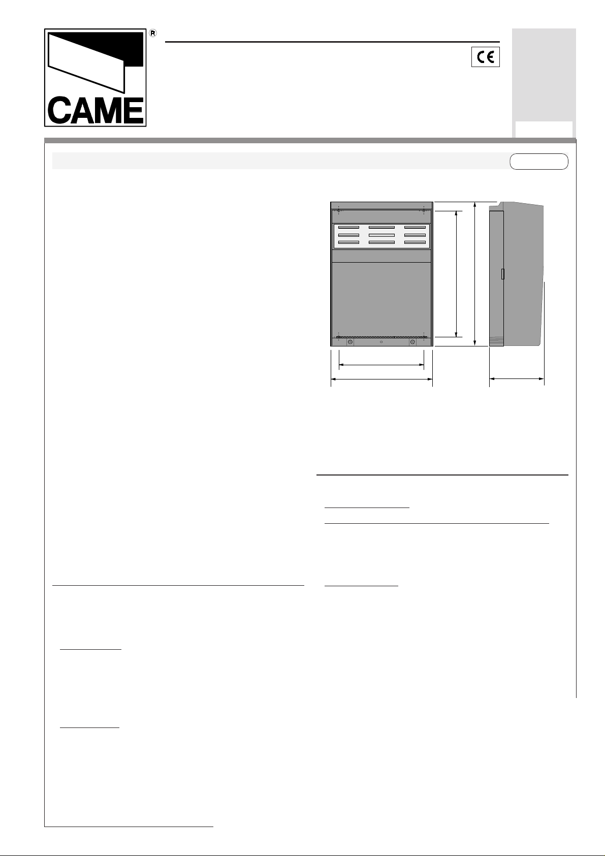
Contenitore in ABS con grado di protezione
IP54, dotato di presa per il riciclo d’aria.
Il quadro deve essere alimentato a 230V
(a.c.) sui morsetti L1 e L2, ed é protetta in
ingresso con fusibile da 1.6A, mentre i
dispositivi di comando a bassa tensione (24V)
sono protetti con fusibile da 3.15A.
La potenza complessiva degli accessori (24V)
non deve superare i 40W.
Il quadro include un sensore amperometrico,
che controlla costantemente la forza sviluppata dal motore in apertura o in chiusura: se
questa supera il livello preimpostato (per
esempio, nel caso ci sia un ostacolo che
blocca il movimento), entra in funzione
arrestando il motore.
Sicurezza
Le fotocellule possono essere collegate e
predisposte per:
-
Riapertura
fotocellule rilevando un ostacolo durante la
fase di chiusura del cancello, provocano
l'inversione di marcia fino alla completa
apertura;
Stop totale
del cancello con l'esclusione
del ciclo di chiusura automatica, per riprendere il
in fase di chiusura (2-C1), le
(1-2), arresto
S66
rev. 0.5
03/2000
©
CAME
CANCELLI
ZL160
290
264
174
197
movimento del cancello, agire sulla
pulsantiera o sul radiocomando;
Accessori opzionali
-
Elettroserratura
Lampada spia cancello aperto
Lampada che segnala la posizione di apertura del cancello, si spegne quando il cancello è
in posizione di chiusura (10-5).
Scheda LB54
tramite batterie nel caso di mancanza di
energia elettrica. Al ripristino della linea
esegue anche la loro ricarica.
12V (2-ES);
. Alimenta i motoriduttori
AUTOMATICI
319S66
ITALIANOITALIANO
ITALIANO
ITALIANOITALIANO
110
(3W max.).
Page 2

Altre funzioni
-
Chiusura automatica.
Il temporizzatore di
chiusura automatica si autoalimenta a
finecorsa in apertura. Il tempo prefissato
regolabile, è in ogni modo subordinato
dall'intervento di eventuali accessori di
sicurezza e si esclude dopo un intervento di
"stop" o in mancanza d'energia elettrica;
"Uomo presente"
-
. Funzionamento del
cancello mantenendo premuto il pulsante
(esclude la funzione del radiocomando). Si
abilita quando il trimmer T.L. è regolato al
minimo.
Colpo d’ariete.
-
Ad ogni comando di apertura, l’anta preme in battuta di chiusura per un
secondo, facilitando l’operazione di sgancio
dell’elettroserratura collegata sui morsetti
2-ES.
É attivo solo se l’anta è chiusa a fine tempo
lavoro.
Regolazioni
- Tempo chiusura automatica;
- Tempo lavoro.
Attenzione! Prima di intervenire all’interno dell’apparecchiatura, togliere la
tensione di linea.
-2-
Page 3

GENERAL CHARACTERISTICS
ENGLISHENGLISH
ENGLISH
ENGLISHENGLISH
Description
The ZL160 control panel is suitable for controlling an automatic system for the FLEX series swing gates powered by 24V d.c. with capacity up to 48W, frequency 50-60 Hz.
Wholly designed and built by CAME CANCELLI AUTOMATICI S.p.A., it meets UNI
8612 regulations in force. ABS case, which
has an IP54 protection level, with air recycling
inlet.
The circuit requires 230V (AC) on terminal
blocks L1 and L2, and is protected with 1.6A
fuse, whilst the low voltage command devices
are protected by a 3,15A fuse.
The accessories total capacity (24V) should
not exceed 40W.
The control panel includes an amperometric
sensor that constantly checks the force developed by the motor when opening or closing: if
this exceeds the preset level (for example, in
the event of an obstacle blocking movement), it
becomes operative and stops the motor.
Safety
Photocells can be connected to abtain:
Re-opening
-
during closure (2-C1), if the
photocells identify an obstacle while the gate
is closing, they will reverse the direction of
movement until the gate is completely open;
Total stop
-
(1-2), shutdown of gate
movement without automatic closing, a
pushbutton or radio remote control must be
actuated to resume movement.
through batteries in case of a power outage.
After the power supply is restored, it also recharges the batteries.
Other functions
-
Automatic closing.
The automatic closing
timer is automatically activated at the end of
the opening cycle. The preset, adjustable
automatic closing time is automatically
interrupted by the activation of any safety
system, and is deactivated after a STOP
command or in case of power failure;
"Operator present"
-
. Gate operates only
when the pushbutton is held down (the radio
remote control system is deactivated). It is
activated when the T.L. trimmer is set to the
minimum;
- Hammer movement.
At every opening command, the wings press the closing stop-ledge
for a second, thus facilitating the release operation of the electric lock connected to terminals 2-ES.
It is only active if the wings are closed and at
the end of the work time.
Adjiustments
- Automatic closure time;
- Operating time.
Optional accessories
-
12V
Electric lock
Gate open pilot lamp
-
(2-ES);
(3W max.). A lamp that
signals the gate’s open position and that goes
out when the gate is in the closed position.
Connected to terminals 10-5.
- LB54 Board
. Powers the reduction gears
Important! Disconnect the unit from the
main power lines before carrying out any
operation inside the unit.
-3-
Page 4
CARACTÉRISTIQUES GÉNÉRALES
FRANÇAISFRANÇAIS
FRANÇAIS
FRANÇAISFRANÇAIS
Description
Le tableau de commande ZL160 sert à
commander les automatismes pour portails à
battant de la série FLEX alimentés à 24V c.c.
avec puissance jusqu’à 48W, fréquence
50÷60 Hz.
Conçue et construite entièrement par CAME
CANCELLI AUTOMATICI S.p.A., elle est
conforme aux normes NFP 25-362 en
vigueur. Boîtier en ABS avec degré de
protection IP54, équipé d’une pr ise pour le
recyclage de l’air.
Le circuit doit être alimentée avec une tension
de 230V (c.a.) aux bornes L1 et L2, et est
protégée à l’entrée par fusible de ligne 1.6A,
tandis que les dispositifs de commande à
basse tension (24V) sont protégés par un
fusible de 3,15A.
La puissance total des accessoires (24V) ne
doit pas dépasser 40W.
Le tableau est équipé d’un capteur
ampèremétrique qui contrôle constamment la
force développée par le moteur en ouverture
ou en fermeture: il intervient en arrêtant le
moteur si celle-ci dépasse le niveau préétabli
(par exemple au cas où un obstacle bloquerait
le mouvement).
Sécurité
Il est possible de brancher des photocellules
et de les programmer pour:
Réouverture
-
en phase de fermeture (2-C1),
les cellules photoélectriques provoquent
l'inversion de marche jusqu'à l'ouverture
complète si elles relèvent un obstacle durant
la phase de fermeture du portail;
Stop total
-
(1-2), arrêt du portail et
désactivation d’un éventuel cycle de
fermeture automatique; pour activer de
nouveau le mouvement, il faut agir sur les
boutons-poussoirs ou sur la radiocommande.
Accessoires en option
-
Serrure électrique
-
Lampe témoin portail ouvert
12V (2-ES);
(3W max.).
Lampe qui signale la position d’ouverture du
portail et s’éteint quand le portail est en
position de fermeture. Elle est branchée sur
les bornes 10-5.
- Carte LB54
. Elle alimente les
motoréducteurs à l’aide de batteries en cas
de coupure de courant. Elle recharge
également les batteries quand le courant est
rétabli.
Autres fonctions
-
Fermeture automatique.
Le temporisateur de
fermeture automatique est autoalimenté à la
fin du temps de la course en ouverture. Le
temps réglable est programmé, cependant, il
est subordonné à l’intervention d’éventuels
accessoires de sécurité et il est exclu après
une intervention de “stop” ou en cas de
coupure de courant;
Fonction “homme mort”
-
. Fonctionnement du
portail en maintenant appuyé le boutonpoussoir (exclut la fonction de la
radiocommande). Il s’active quand le
compensateur T.L. est réglé au minimum;
Coup de bélier.
-
Les vantaux appuient contre
la butée de fermeture pendant une seconde à
chaque commande d’ouverture en facilitant
l’opération de déclenchement de la serrure
électrique branchée aux bornes 2-ES.
Il n’est activé qu’à la fin du temps de travail et
si les vantaux sont fermés.
Réglages
- Temps de fermeture automatique;
- Temps de fonctionnement.
Attention! Avant d’inter venir à l’intér ieur
de l’appareillage, couper la tension de
ligne.
-4-
Page 5

ALLGEMEINE MERKMALE
DEUTSCHDEUTSCH
DEUTSCH
DEUTSCHDEUTSCH
Beschreibung
Die Schalttafel ZL160 eignet sich zur
Steuerung von Automatiksystemen für
Flügeltore der Serie FLEX mit einer
Versorgungsspannung von 24 V DC, einer
Leistung von max. 48 W und einer Frequenz
von 50-60 Hz.
Entwurf und Konstruktion sind von der CAME
CANCELLI AUTOMATICI S.p.A.; sie
entspricht den geltenden Richtlinien UNI
8612. Der Kasten ist in ABS, Schutzgrad IP54
mit Anschluß für die Luftrückführung.
Die Versorgung des Stromkreíses erfolgt mit
230V (Wechselstrom) über die Klemmen L1L2 und ist am Eintritt durch 1.6A-Sicherungen
geschützt. Die Steuervorrichtungen
funktionieren mit Unterspannung (24V) und
sind durch eine 3,15A-Sicherung geschützt.
Die Gesamtleistung der Zubehörteile (24V)
darf 40W nicht übersteigen.
Zur Steuerung gehört ein Sensor zur
Strommessung, der eine konstante Kontrolle
der vom Motor beim Öffnen und Schließen
entwickelten Kraft durchführt. Sollte die Kraft
den vorgegebenen Schwellenwert
übersteigen - z.B. wenn die Bewegung durch
ein Hindernis blockiert wird - schaltet sich der
Sensor zu und löst das Abschalten des
Motors aus.
Sicherheitsvorrichtungen
Die Lichtschranken können für folgende
Funktionen angeschlossen bzw. vorbereitet
werden:
Wiederöffnen
-
beim Schließen (2-C1), die
Lichtschranken ermitteln ein Hindernis
während des schließens vom Tor und lösen
die Umkehr der Laufrichtung vom Tor aus, bis
dieses wieder vollständig geöffnet ist;
Totalstop
-
(1-2), sofortiger Stillstand des
Tores mit Ausschluß eventueller
Schließautomatik: Fortsetzung des Torlaufs
über Drucktaster- bzw. Funksendersteuerung;
Extrazubehör
-
Elektroschloß
- Kontrolllampe Tor offen
12V (2-ES);
(3W max.). Zeigt an,
daß das Tor offen ist und geht aus, wenn das
Tor wieder geschlossen ist. Wird an die
Klemmen 10-5 angeschlossen.
- Karte LB54
. Versorgt die Getriebemotoren
bei Stromausfall mithilfe von Batterien. Sobald
der Strom wieder da ist, werden die
Notbatterien automatisch aufgeladen.
Andere Wahlfunktionen
-
Schließautomatik
. Der SchließautomatikZeischalter speist sich beim Öffnen am Ende
der Torlaufzeit selbst . Die voreingestellte Zeit
ist auf jeden Fall immer dem Eingriff
ev entueller Sicherheitsv orrichtungen
untergeordnet und schließt sich nach einem
“Stop”-Eingriff bzw. bei Stromausfall selbst
aus;
Funktion “Bedienung vom Steuerpult”
-
.
Torbetrieb durch Drucktasterbetätigung
(Funkfernsteuerung ausgeschlossen). Wird
dann eingeschaltet, wenn der Trimmer T.L. auf
das Minimum gestellt ist;
-
Widderstoß:
Jedesmal, wenn der Befehl zum
Öffnen gegeben wird, drücken die Torflügel
eine Sekunde lang gegen den Endanschlag
vom Schließen, so daß die Entriegelung vom
Elektroschloß vereinfacht wird, das an die
Klemmen 2-ES angeschlossen ist.
Der Widderstoß ist nur bei geschlossenen
Torflügeln aktiviert, bei Arbeitsende.
Einstellungen
- Zeit für das automatische Schließen;
- Laufzeit.
Achtung! vor Eingriff im Innern des
Gerätes den Netzstecken ziehen.
-5-
Page 6

CARACTERISTICAS GENERALES
ESPANOLESPANOL
ESPANOL
ESPANOLESPANOL
Descripción
El cuadro de mando ZL160 sirve para accionar las automatizaciones para cancelas de
batiente de la serie FLEX alimentadas a 24V
c.c. con potencia de hasta 48W, frecuencia
50÷60 Hz.
Diseñado y fabricado completamente por
CAME CANCELLI AUTOMATICI S.p.A.,
responde a las normas UNI 8612 vigentes.
Caja de ABS con grado de protección IP54,
con toma para recirculación de aire.
El circuito se alimentato con tensión a 230V
(c.a.) en los bornes L1 y L2, y está protegido
en entrada con fusible de 1.6A, mientras que
los dispositivos de mando de baja tensión
(24V) están protegidos con fusible de 3,15A.
La potencia total de los accesorios (24V) no
tiene que superar los 40W.
El cuadro incluye un sensor amperimétrico
que controla constantemente la fuerza desarrollada por el motor durante la apertura o el
cierre: si dicha fuerza supera el nivel
predefinido (por ejemplo, si hay un obstáculo
que bloquea el movimiento), entra en funcionamiento deteniendo el motor.
Seguridad
Las fotocélulas pueden estar conectadas y
predispuestas para:
Reapertura
-
en la fase de cierre (2-C1), las
fotocélulas detectan un obstáculo durante el
cierre de la puerta, provocando la inversión
de marcha hasta la apertura completa;
Parada total
-
(1-2), parada de la puerta
excluyendo el posible ciclo de cierre
automático; para reactivar el movimiento es
preciso actuar en el teclado o en el mando a
distancia;
max.). Lámpara que señala la posición de
apertura de la cancela, se apaga cuando la
cancela está en posición de cierre. Conectada a los bornes 10-5.
- Tarjeta LB54
. Alimenta los motorreductores
con las baterías si falta energía eléctrica. Al
restablecer la línea, también recarga las baterías.
Otras funciones
-
Cierre automático
. El temporizador de cierre
automático se autoalimenta en fin-de-tiempo
carrera en fase de apertura. El tiempo
prefijado regulable, sin embargo, está
subordinado a la intervención de posibles
accesorios de seguridad y se excluye
después de una intervención de parada o en
caso de falta de energía eléctrica;
Función a "hombre presente"
-
. Funcionamiento de la puerta manteniendo
pulsada la tecla (excluye la función del mando
a distancia). Se activa cuando el trimmer T.L.
está regulado en el mínimo;
Golpe de ariete.
-
Cada vez que se da un
mando de apertura, las hojas presionan en el
tope de cierre por un segundo, facilitando la
operación de desenganche de la cerradura
eléctrica conectada en los bornes 2-ES.
Está activo sólo si las hojas están cerradas y
al final del tiempo de funcionamiento.
Regulaciones
- Tiempo de cierre automático;
- Tiempo trabajo.
Accesorios opcionales
-
Cerradura eléctrica
-
Lámpara indicadora cancela abierta
-6-
12V (2-ES);
¡Atención! Antes de actuar dentro del
aparato, quitar la tensión de línea.
(3W
Page 7

SCHEDA BASE -
MOTHERBO ARD
- CARTE BASE -
GRUNDPLATINE
- TARJETA BASE
I
COMPONENTI PRINCIPALI
1 Morsettiere di collegamento
2 Fusibile di linea 1.6A
3 Fusibile accessori 3.15A
4 Pulsante memorizzazione codice radio
5 Trimmer di regolazione tempo lavoro
6 Trimmer di regolazione tempo di
chiusura automatica
7 Selettore funzioni a 4 dip (vedi pag. 9)
8 Innesto scheda radiofrequenza (vedi
tabella)
9 LED segnalazione
GB
MAIN COMPONENTES
44
55
77
5
7
55
77
T.L. T.C.A.
2143
33
3
33
22
2
22
FUSIBILE LINEA 5A
11
1
11
F
PRINCIPAUX COMPOSANTS
FUSIBILE CENTR. 3.15A
66
4
6
44
66
QUADRO COMANDO
ZL160
99
9
99
88
8
88
AF43S/SM
1 Terminal block for external conections
2 Line fuse, 1.6A
3 Fuse on accessory power line, 3,15A
4 Radio-code save button
5 Trimmer for adjustment operating time
6 Trimmer for adjustment automatic closing
7 4-dip function switch (see pag. 9)
8 Socket AF radiofrequency board (see
table)
9 Signal LED
D E
HAUPTKOMPONENTEN
1 AnschlußKlemmenleiste
2 Hauptsicherung 1,6A
3 Zubehör-Sicherung 3,15A
4 Knöpfe zum Abspeicher der
Radiocodes
5 Trimmer zur Einstellung Laufzeit
6 Trimmer zur Einstellung
Schließautomatik
7 Wählschalter für Funktionen mit 4 Dip
(sehen S. 9)
8 Steckanschluß Funkfrequenze-Platine
AF (sehen Tabelle)
9 LED Kontrolleuchte zur Anzeige
1 Plaque à bornes de connexion
2 Fusible de ligne 1,6A
3 Fusible accessoires 3,15A
4 Bouton-poussoir mémorisation code
radio
5 Trimmer de réglage temps de
fonctionnement
6 Trimmer de réglage fermeture
automatique
7 Selecteur de fonctions à 4 interrupteurs
à positions multiples (voir pag. 9)
8 Branchement carte radiofréquence AF
(voir tableau)
9 LED de signalisation
PRINCIPALES COMPONENTES
1 Caja de bornes para las conexiónes
2 Fusible de línea 1,6A
3 Fusible accesorios 3,15A
4 Tecla de memorización del código radio
5 Trimmer de regulación tiempo trabajo
6 Trimmer de regulación tiempo cierre
automático
7 Selector de funciones con 4 dip (vedas
pag. 9)
8 Conexión tarjeta radiofrecuencia AF
(vedas tabla)
9 LED de señal
-7-
Page 8

L1L1
L1
L1L1
L2L2
L2
L2L2
MM
M
MM
NN
N
NN
1010
10
1010
E E
E
E E
COLLEGAMENTI ELETTRICI -
ELEKRISCHE ANSCHLÜSSE -
L1 L2 10 11 E ES 1 5 72C1MN
Alimentazione 230V (a.c.)
230V (a.c.) power input
Alimentation 230V (c.a.)
Stromversorgung 230V (Wechselstrom)
Alimentación 230V (a.c.)
Motore 24V (d.c.)
24V (d.c.) motor
M
Moteur 24V (c.c.)
Einphasenmotor 24V (Gleichstrom)
Motor 24V (d.c.)
Uscita 24V (a.c.) in movimento
(es.lampeggiatore - max. 25W)
24V (a.c.) output in motion
(e.g. flashing light - max. 25W)
Sortie 24V (c.a.) en mouvement
(ex. branchement clignotant - max. 25W)
Ausgang 24V (Wechselstrom) in Bewegung
(z.B. Blinker-Anschluß - max. 25W)
Salida de 24V (a.c.) en movimento
(p.ej. conexión lámpara intermitente - max. 25W)
ELECTRICAL CONNECTIONS -
CONEXIONES ELÉCTRICAS
BRANCHEMENTS ÉLECTRIQUES
-8-
1010
10
1010
5 5
5
5 5
22
2
22
77
7
77
2 2
2
2 2
C1C1
C1
C1C1
11
1
11
22
2
22
Lampada spia (24V-3W max.) "cancello aperto"
(24V-3W max.) "gate-opened" signal lamp
Lampe-témoin (24V-3W max.) "portail ouverture"
Signallampe (24V-3W max.) "Tor Öffnen"
Lámpara indicadora (24V-3W max.) "puerta abierta"
Contatto radio e/o pulsante per comando (vedi dip 2)
Contact radio and/or button for control (see dip 2)
Contact radio et/ou poussoir pour commande (voir dip 2)
Funkkontakt und/oder Taste Steuerart (siehe Dip 2)
Contacto radio y/o pulsador para mando (mirar dip 2)
Contatto (N.C.) di «riapertura durante la chiusura»
Contact (N.C.) for «re-opening during the closing»
Contact (N.F.) de «réouverture pendant la fermeture»
Kontakt (Ruhekontakt) «Wiederöffnen beim Schliessen»
Contacto (N.C.) para la «apertura en la fase de cierre»
Pulsante stop (N.C.)
Pushbutton stop (N.C.)
Bouton-poussoir arrêt (N.F.)
Stop-Taste (N.C.)
Pulsador de stop (N.C.)
Page 9

1010
É
10
1010
1111
11
1111
-5
N.B.Tutti i
contatti e
pulsanti (N.C.)
non collegati ad
accessori
devono essere
cortocircuitati
sulla
morsettiera.
REGOLAZIONI -
Alimentazione accessori 24V (a.c.) max. 40W
24V (a.c.)Powering accessories (max 40W)
Alimentation accessoires 24V (c.a.) max. 40W
Zubehörspeisung 24V (Wechselstrom) max. 40W
Alimentación accesoios 24V (a.c.) max. 40W
Collegamento elettroserratura 12V (a.c.) 15W max.
12V (a.c.) 15W max. connection for electrically-actuated lock
Connexion serrure électrique 12V (c.a.) 15W max.
Anschluß Elektroschloß 12V (Wechselstrom) 15W max.
Conexión electrocerradura 12V (a.c.) 15W max.
Collegamento antenna
Antenna connection
Connexion antenne
Antennenanschluß
Conexión antena
N.B. A bridge
connection must
be applied across
all (N.C.) contacts
and normallyclosed pushbutton
connections
which are not
connected to
accessories.
Apply the bridge
connections at the
terminal board.
ADJUSTMENTS
N.B: Tous les
contacts et les
poussoirs (N.F.)
doivent être
courtcircuités
sur la plaque à
bornes s'ils ne
sont pas
connectés aux
accessoires.
- RÉGLA GES -
EINSTELLUNGEN
HINWEIS:Alle
Kontakte und
Tasten (N.C.), an
die kein Zubehör
angeschlossen
ist, müssen auf
dem Klemmenbrett
kurzgeschlossen
werden.
- REGULACIONES
NOTA:Todos los
contactos y
pulsadores
(N.C.) no
conexionados a
accessorios
deben ser
cortocircuitados
sobre la regleta
de bornes.
I
Trimmer T.L.
= Regolazione tempo lavoro
(min.15”, max.80”).
(Nota: regolando al minimo il tempo lavoro
si abilita la funzione «uomo presente»).
Trimmer T.C.A.
= Regolazione tempo di
chiusura automatica (min.0”, max.120”).
GB
Trimmer T.L.
= Adjustment of operating
time (min.15”, max.80”).
(Note: the "operator present" function is
activated by setting the operating time to
the minimum).
Trimmer T.C.A.
= Adjustment automatic
closing time (min.0”, max.120”)
D
Trimmer T.L.
= Einstellung der Laufzeit
(min.15”, max.80”).
(Hinweis: Wenn die Betriebsdauer auf ein
Minimum gestellt wird, wird die Funktion
"Bedienung vom Steuerpult" eingeschaltet).
Trimmer T.C.A.
= Zeiteinstellung
Schließautomatik (min.0”, max.120”).
T.L. T.C.A.
2143
F
Trimmer T.L.
QUADRO COMANDO
ZL160
M
REGOLAZIONE TRIMMERS
TRIMMERS ADJUSTMENT
R
GLAGE TRIMMERS
EINTE LLUNG TRI MMER S
REGULACIÓN TRIMMERS
T.L. T.C.A.
= Réglage du temps de
fonctionnement (min.15”, max.80”).
(Note: la fonction "homme mort" s'active en
réglant le temps de fonctionnement au
minimum).
Trimmer T.C.A.
= Réglage du temps de
fermeture automatique (min.0”, max.120”).
E
Trimmer T.L.
= Regulación tiempo de
trabajo (min.15”, max.80”).
(Nota: regulando en el mínimo el tiempo
de trabajo, se activa la función "hombre
presente").
Trimmer T.C.A.
= Regulación cierre
automático (min.0”, max.120”).
-9-
Page 10

SELEZIONI FUNZIONI -
FUNKTIONSWAHL
I
SELECTION OF FUNCTIONS
- SELECCIÓN DE LAS FUNCIONES
1 ON Chiusura automatica attivata;
(1 OFF - disattivata)
2 ON "Apre-stop-chiude-stop” con
pulsante (2-7) e radiocomando
(scheda AF inserita) attivato;
2 OFF "Apre-chiude” con pulsante (2-7) e
radiocomando (scheda AF inserita) attivato;
3 Non utilizzato, tenere il dip in
posizione “OFF”;
4 ON Colpo d’ariete per facilitare lo
sgancio della serratura attivato;
(4OFF-disattivato).
- SÉLECTION FONCTIONS
ON
2143
OFF
T.L. T.C.A.
2143
FUSIBILE LINEA 5A FUSIBILE CENTR. 1A
QUADRO COMANDO
ZL160
AF43S/SM
GB
1 ON Automatic closing enabled;
(1 OFF - disabled)
2 ON "Open-stop-close-stop” with button
(2-7) and radio control (AF board
inserted) enabled;
2 OFF "Open-close” with button (2-7) and
radio control (AF board inserted)
enabled;
3 Not used, keep the dip in position
“OFF”;
4 ON Hammer movement operation, this
function helps unlock the electric
lock enabled; (4OFF - disabled).
D
1 ON Schließautomatik aktiviert;
(1 OFF - deaktiviert)
2 ON “Öffnen-Stop-Schließen-Stop” mit
Druckknopf (2-7) und
Fernsteuerung (Karte AF
eingesteckt) aktiviert;
2 OFF “Öffnen-Schließen” mit Druckknopf
(2-7) und Fernsteuerung (Karte AF
eingesteckt) aktiviert;
3 Nicht in Gebrauch, lassen Sie den
Dip-Schalter auf “OFF” stehen;
4 ON Widderstoß aktiviert; (durch diese
Funktion wird das Auslösen des
Elektroschlosses erleichtert) 4 OFF
- deaktiviert;
F
1 ON Fermeture automatique activé;
(1 OFF - éteinte)
2 ON "Ouvre-stop-ferme-stop” avec
bouton (2-7) et radio commande
(carte AF insérée) activé;
2 OFF "Ouvre-ferme” avec bouton (2-7) et
commande-radio (carte AF
insérée) activé;
3 Pas utilisé, garder le commutateur
à basculé sur “OFF”;
4 ON Fonction coup de bélier pour
faciliter le déblocage de la serrure
activé; (4OFF- éteinte).
E
1 ON Cierre automático activado;
(1 OFF - desactivado)
2 ON “Abrir-parada-cerrar-parada” con
botón (2-7) y radiocontrol (tarjeta
AF conectada) activado;
2 OFF “Abrir-cerrar” con botón (2-7) y
radiocontrol (tarjeta AF conectada)
activado;
3 No se utilizza, mantenga el dip en
posición “OFF”;
4 ON Golpe de ariete activado; (esta
función sirve para agilizar
desenganche de la
elecrocerradura (4 OFF desactivado)
-10-
Page 11

ITALIANO
INSTALLAZIONE DEL
RADIOCOMANDO
ENGLISH
RADIO CONTROL
INSTALLATION
FRANÇAIS
INSTALLATION DE LA
RADIOCOMMANDE
DEUTSCH
INSTALLATION DER
RADIOSTEUERUNG
ESPANOL
INSTALACIÓN DEL
RADIOMANDO
-PROCEDURA-
A. inserire una
scheda AF.
B. codificare i
trasmettitori.
C. memorizzare
la codifica
sulla scheda base.
INSERIMENTO SCHEDA AF -
A
La schedina AF deve
essere inserita
OBBLIGATORIAMENTE in
assenza di tensione.
-PROCEDURE-
A. insert an AF
card.
B. encode
transmitters.
C. store code in
the
motherboard.
EINSTECKEN DER KARTE AF /
-PROCEDURE-
A. placer une
carte AF.
B. codifier les
émetteurs.
C. mémoriser la
codification
sur la carte
base.
AF BOARD INSERTION
T.L. T.C.A.
4
-PROZEDUR-
A. Stecken Sie
-PROCEDIMIENTO-
A. introducir una
eine KarteAF.
B. Codieren Sie
B. codificar los
die Sender.
C. Speichern
C. memorizar la
Sie die
Codierung
auf der
Grundplatine.
- NSTALLATION DE LA CARTE AF
MONTAJE DE LA TARJETA AF
QUADRO COMANDO
ZL160
SCHEDA BASE
MOTHERBOARD
CARTE DE BASE
BASISKARTE
TARJETA BASE
tarjeta AF.
transmisores.
codificación
en la tarjeta
base.
The AF board should
ALWAYS be inserted when the
power is off.
La carte AF doit
OBLIGATOIREMENT être
branchée en l’absence de
tension.
Vor Einschieben der Karte
die Stromzufuhr UNBEDINGT
abschalten.
La tarjeta AF se debe
montar OBLIGATORIAMENTE
en caso de falta de
corriente.
AF
Frequenza / MHz
Frequency / MHz
Frequence / MHz
Frequenz / MHz
Frecuencia / MHz
FM 26.995 AF130 TFM
FM 30.900 AF150 TFM
AM 26.995 AF26 TOP
AM 30.900 AF30 TOP
AM 433.92
Scheda radiofrequenza
Radiofrequency board
Carte radiofréquence
Funkfrequenz-Platine
Tarjeta radiofrecuencia
AF43S / AF43SM TAM / TOP
AF43SR ATOMO
SCHEDA "AF"
"AF" BOARD
CARTE "AF"
KARTE «AF»
TARJETA «AF»
Trasmettitore
Transmitter
Emetteur
Funksender
Transmisor
-11-
Page 12

CODIFICA TRASMETTITORI -
CODIERUNG DER SENDER
TRANSMITTER ENCODING
- CODIFICACIÓN TRANSMISORES
- CODIFICATION DES EMETTEURS
TOP
PROCEDURA COMUNE DI
CODIFICA
1.segnare un codice (anche
per archivio)
2.inserire jumper codifica J
3.memorizzarlo
4.disinserire jumper J
ANLEITUNGEN ZUR
CODIERUNG
1.Ordnen Sie einen Code zu
(auch für das Archiv).
2.Schalten Sie den
Codierungs-Jumper J ein.
3.Speicher n Sie den Code.
4.Schalten Sie den Jumper J
wieder aus.
QUARZATI
-
QUARTZ
STANDARD ENCODING
1.assign a code (also on file)
2.connect encoding jumper J
3.register code
4.disconnect jumper J
PROCEDIMIENTO COMÚN DE
1.marcar un código (también
para el archivo)
2.conectar un jumper
codificación J
3.registrar el código
4.desconectar jumper J
- AU QUARTZ
PROCEDURE
CODIFICACIÓN
-
QUARTZGENAUE
1.taper un code (également
2.placer un cavalier de
3.mémoriser le code
4.enlever le cavalier J
- CUARZO
PROCEDURE COMMUNE DE
CODIFICATION
pour les archives)
codification J
1.
3.
codice/
P1
P2
premere in sequenza P1 o P2 per registrare il
codice; al decimo impulso un doppio suono
confermerà l'avvenuta registrazione
Press P1 or P2 in sequence in order to register the
code; at the tenth pulse, a double beep will confirm
that registration has occurred
appuyer en séquence sur P1 ou P2 pour mémoriser
le code; à la dixième impulsion, une double
sonnerie confirme que le code a été mémorisé
Drücken Sie nacheinander P1 oder P2, um den
Code zu speichern. Nach dem zehnten Impuls
signalisiert ein doppelter Piepton, daß der Code
gespeichert worden ist.
oprimir repetidamente P1 ó P2 para registrar el
código; con el décimo impulso un doble sonido
señalará que el registro se ha efectuado.
codice
/codice/
codice
/codice
OFF
ON
P1=OFF
2.
J
P2=ON
4.
J
-12-
Page 13

P1 P2
T262M - T302M
La prima codifica deve essere effettuata mantenendo i jumper
posizionati per i canali 1 e 2 come da fig. A; per eventuali e successive impostazioni su canali diversi vedi fig. B
J
The first encoding operation must be carried out whilst keeping the
jumpers positioned for channels 1 and 2 as per fig. A; see fig. B for
any subsequent settings on different channels.
La première codification doit être effectuée en maintenant les
cavaliers en position pour les canaux 1 et 2, comme d'après la fig.
A; pour des saisies successives éventuelles sur des canaux
différents, voir fig. B
Für die erste Codierung muß der Jumper auf den Kanälen 1 und 2
positioniert bleiben (siehe Abb. A). Für eventuelle weitere oder
spätere Einstellungen auf anderen Kanälen halten Sie sich bitte an
Abb. B.
La primera codificación tiene que efectuarse manteniendo los
jumper conectados para los canales 1 y 2 como se ilustra en la fig.
A; para planteamientos posteriores en canales distintos ver la fig. B
fig. A
P1 P2
P3 P4
2° codice/
fig. B
P1=CH1
P2=CH2
T2622M - T3022M
1° codice/
codice/
codice
codice
/codice
J
P1=CH1
P2=CH2
codice
/codice/
codice
P1=CH1 - P2=CH3
P1=CH1 - P2=CH4
/codice
P1=CH3 - P2=CH2
P1=CH3 - P2=CH4
T264M - T304M
P1=CH1 - P2=CH2
P3=CH3 - P4=CH4
P1 P2
P3 P4
J
J
P1
P2
OFF
ON
P3=CH1
P4=CH2
-13-
Page 14

B
CODIFICA TRASMETTITORI -
CODIERUNG DER SENDER
see instruction sheet inside the pack of AF43SR circuit card
Siehe Anleitungen, die der Packung beiliegen der Platine AF43SR
impostare il codice sul dip-switch C e il canale su D (P1=CH1 e P2=CH2,
impostazione di default)
set the code to dip-switch C and channel to D (P1=CH1 and P2=CH2, default
setting)
saisir le code sur le commutateur dip C et le canal sur D (P1=CH1 et P2=CH2,
saisie de défaut)
Stellen Sie den Code auf den Dip-Switch C und den Kanal auf D (P1=CH1
und P2=CH2; Grundeinstellung).
plantear el código en el dip-switch C y el canal en D (P1=CH1 y P2=CH2,
planteamiento por defecto)
P1 P2
D
1 2 3 4
1 2 3 4 5 6 7 8 9 10
TRANSMITTER ENCODING
- CODIFICATION DES EMETTEURS
- CODIFICACIÓN TRANSMISORES
ATOMO
AT01 - AT02
vedi foglio istruzioni inserito nella confezione
della scheda AF43SR
voir les instructions qui se trouve dans l'emballage
de la carte AF43SR
ver hoja de instrucciones adjunta en el embalaje
de la tarjeta AF43SR
TOP
T432M - T312M
P1
1 2 3 4 1 2 3 4 1 2 3 41 2 3 4
CH1 CH2 CH3
CH4
P1 P2
P3 P4
P1=CH1
P2=CH2
P3=CH3
P4=CH4
1 2 3 4 5 6 7 8 9 10
TAM
C
T434M - T314M
impostare solo il codice
set code only
ne saisir que le code
Stellen Sie nur den Code ein.
plantear sólo el código
C
T432
T434
T438
vedi foglio istruzioni inserito nella
voir la notice d'instructions qui se trouve
ver hoja de instrucciones adjunta en el
P2
1 2 3 4 1 2 3 4 1 2 3 4 1 2 3 4
CH1 CH2 CH3
voir instructions sur l'emballage
Siehe Anleitungen auf der Pac kung.
ver instrucciones en el embalaje
confezione
see instruction sheet inside the pack
dans l'emballage
Siehe Anleitungen, die der Pac kung
beiliegen.
embalaje
CH4
T432S / T432SA
vedi istruzioni su confezione
see instructions on pack
TFM
T132
T134
T138
T152
T154
T158
-14-
Page 15

C
MEMORIZZAZIONE CODICE -
SPEICHERN VOM CODE
CODE STORA GE
- MEMORIZACIÓN CÓDIGO
- MEMORISATION DU CODE
ITALIANO
Memorizzare la
codifica sulla
scheda, nel
seguente modo:
a) tenere
premuto il tasto
"PROG" sulla
scheda base, il
led di segnalazione lampeggia;
b) con un tasto
del trasmettitore
s'invia il codice,
il led rimarrà
acceso a
segnalare
l'avvenuta
memorizzazione.
ENGLISH
Memorize the
code on the
board in this
way:
a) keep the
PROG key
pressed on the
base card, the
signal LED will
flash;
b) with a key on
the transmitter
the code is sent,
the LED will
remain lit to
signal the
successful
saving of the
code.
FRANÇAIS
Mémoriser le
code sur la
carte de la
façon suivante;
a) appuyer sur
la touche
"PROG" sur la
carte de base,
le led de
signalisation
clignote,
b) avec une
touche du
emetteur on
envoie le code,
le led restera
allumé pour
signaler que la
mémorisation
s'est effectuèe.
DEUTSCH
Speichern Sie
die Codierung af
der Basiskarte
und halten Sie
dazu
folgendermaßen
vor:
a) Halten Sie
die Taste PROG
an der
Basiskarte
gedrückt, die
Kontrolleuchte
blinkt
b) Senden Sie
den Code mit
einer Taste vom
Sender. Der
Kontrolleuchte
bleibt jetzt an
und zeigt
dadurch das
erfolgte
Speichern an.
ESPANOL
Memorice la
codificación en
la tarjeta de la
siguiente
manera:
a) Mantener
oprimida la tecla
"PROG" en la
tarjeta base, el
led de
señalización
parpadea,
b) con una tecla
del transmisor
se envía el
código, el led
permanece
encendido para
indicar que el
almacenamendo
se ha
efectuado.
a)
ILE CENTR. 1A
AP.PARZ.
PROG
T.L. T.C.A.
2143
LED intermittente
flashing LED
LED clignotant
LED Aufblinkende
LED intermitente
QUADRO C OMANDO
ZL160
AF43S/SM
b)
ILE CENTR. 1A
AP.PARZ.
T.L. T.C.A.
2143
LED acceso
Lit LED
LED allumé
LED Kontrolleuchte
LED encendido
QUADRO COMANDO
ZL160
AF43S/SM
-15-
Page 16

CANCELLI AUTOMATICI
CAME CANCELLI AUTOMATICI S.P.A.
(+39) 0422 (+39) 0422 490944
SSISTENZA TECNICA
A
NUMERO VERDE
800 295830
W
EB
www.came.it
E-
MAIL
info@came.it
DOSSON DI CASIER (TREVISO)
SISTEMA Q U ALITÀ
CERTIFICATO
CAME LOMBARDIA S.R.L.___COLOGNO M. (MI)
(+39) 02 26708293 (+39) 02 25490288
CAME SUD S.R.L. _________________NAPOLI
(+39) 081 752445 (+39) 081 7529109
CAME (AMERICA) L.L.C._________MIAMI (FL)
(+1) 305 5930227 (+1) 305 5939823
CAME AUTOMATISMOS S.A_________MADRID
(+34) 091 5285009 (+34) 091 4685442
CAME BELGIUM____________LESSINES
(+32) 068 333014 (+32) 068 338019
CAME FRANCE S.A.___NANTERRE CEDEX (PARIS)
(+33) 01 46130505 (+33) 01 46130500
CAME GMBH____KORNTAL BEI (STUTTGART)
(+49) 07 11839590 (+49) 07 118395925
CAME GMBH________SEEFELD BEI (BERLIN)
(+49) 03 33988390 (+49) 03 339885508
CAME PL SP.ZO.O_________WARSZAWA
(+48) 022 8699933 (+48) 022 6399933
CAME UNITED KINGDOM LTD___NOTTINGHAM
(+44) 01159 387200 (+44) 01159 382694
 Loading...