

Page 1
SERIE Z |
Z
SERIES
| SÉRIE Z |
BAUREIHE
Z |
SERIE Z
Documentazione
Tecnica
QUADRO COMANDO
CONTROL PANEL
ARMOIRE DE COMMANDE
SCHALTTAFEL
CUADRO DE MANDO
CARATTERISTICHE GENERALI
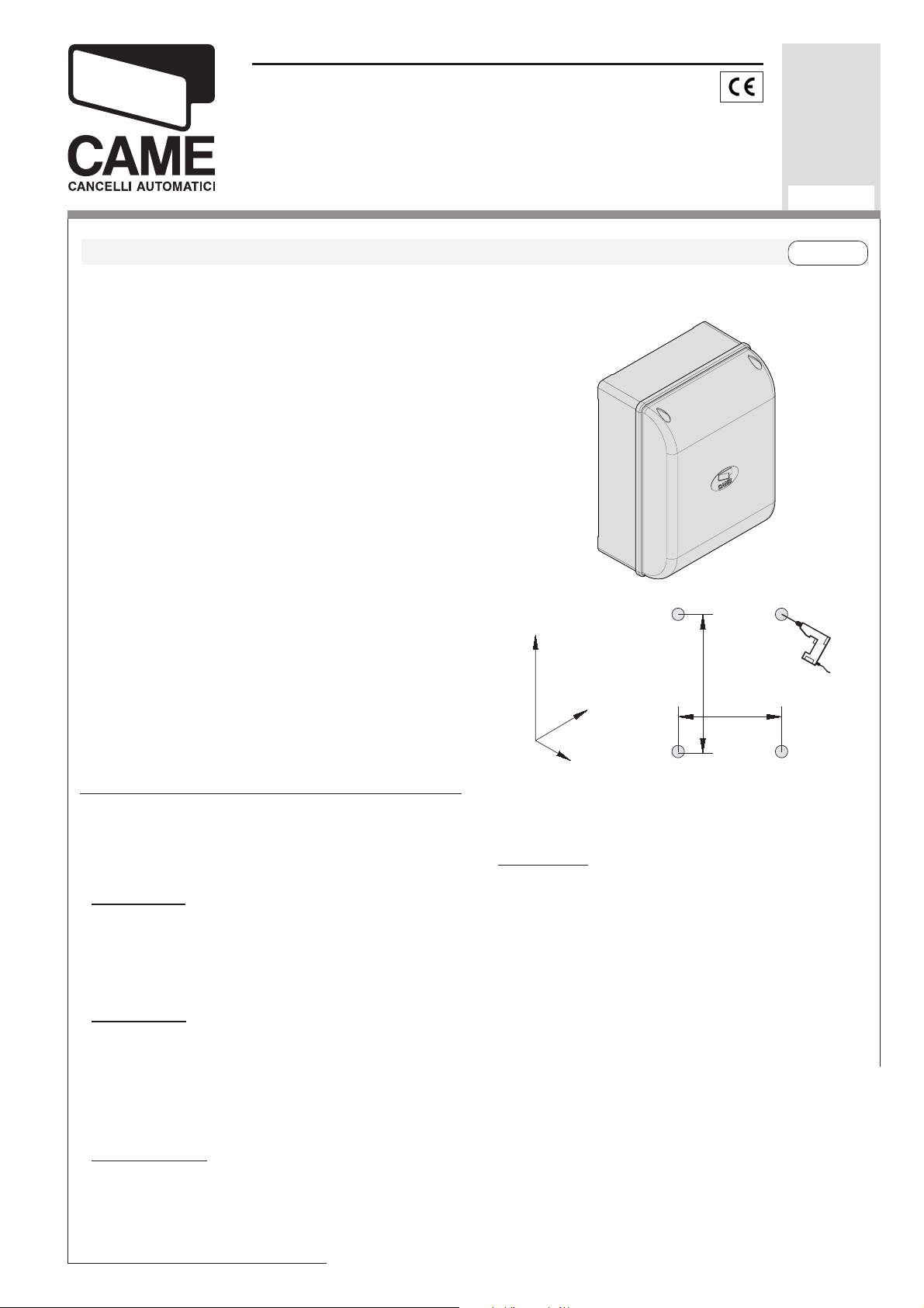
Descrizione
Il quadro comando ZL150N è adatto al
comando di automazioni per cancelli a
a 2 battenti della serie FLEX alimentate a
24Vd.c., con potenza fino a 48W.
Progettato e costruito interamente dalla
CAME S.p.A., risponde alle vigenti norme di
sicurezza con grado di protezione IP54.
Contenitore in ABS.
Garantito 24 mesi salvo manomissioni.
ZL150N
U37
rev. 0.1
12/2006
©
CAME
CANCELLI
AUTOMATICI
319U37
ITALIANOITALIANO
ITALIANO
ITALIANOITALIANO
Il circuito va alimentato con tensione di 230V
(a.c.) sui morsetti L1-L2 e protetto in ingresso
con un fusibile di linea da 1.6A.
I dispositivi di comando sono a bassa
tensione e protetti con fusibile da 1.6A,
mentre il motoriduttore e l’elettroserratura
sono protetti con fusibile da 5A.
La potenza complessiva degli accessori
(24V) non deve superare i 40W.
Sicurezza
Le fotocellule possono essere collegate e
predisposte per:
-
Riapertura
in fase di chiusura (2-C1), le
fotocellule rilevando un ostacolo durante la
fase di chiusura del cancello, provocano
l'inversione di marcia fino alla completa
apertura;
Richiusura
-
in fase di apertura (2-CX, dip
8OFF-10OFF), le fotocellule rilevando un
ostacolo durante la fase di apertura del
cancello, provocano l'inversione di marcia fino alla
completa chiusura;
274
254
204
184
133
ca (2-CX, dip 8OFF-10ON);
Stop totale
l'esclusione del ciclo di chiusura automatica;
per riprendere il movimento bisogna agire
sulla pulsantiera o sul radiocomando;
Nota
: Se un contatto di sicurezza normalmente chiuso (2-C1, 2-CX, 1-2) si apre, viene
segnalato dal lampeggio del LED segnalazione.
(1-2), arresto del cancello con
Stop parziale
-
, arresto del
cancello se in movimento
con conseguente predisposizione alla chiusura automati-
Page 2
Accessori opzionali
-
Lampada di segnalazione "cancello aperto"
(3W)
. Lampada che segnala la posizione di
apertura del cancello a battente, si spegne
quando il cancello attiva il finecorsa chiude.(10-5);
Elettroserratura
-
Scheda LB54
-
(2-S);
. Alimenta i motoriduttori
tramite batterie nel caso di mancanza di
energia elettrica. Al ripristino della linea
esegue anche la loro ricarica.
Altre funzioni
-
Chiusura automatica.
Il temporizzatore di
chiusura automatica si autoalimenta a finetempo corsa in apertura. Il tempo prefissato
regolabile, è comunque subordinato dall'intervento di eventuali accessori di sicurezza e si
esclude dopo un intervento di "stop" o in
mancanza di energia elettrica;
-
Prelampeggio
di 5 secondi sia in apertura
che in chiusura delle ante;
Tipo di comando:
-
-apre-stop-chiude-stop con pulsante e/o
trasmettitore;
-apre-chiude-inversione con pulsante e/o
trasmettitore;
-solo apre per trasmettitore.
Regolazioni
- Tempo chiusura automatica;
- Tempo apertura parziale e ritardo chiusura
del 2° motore;
- Tempo lavoro.
Rilevazione di presenza ostacolo
-
. A motore
fermo (cancello chiuso, aperto o dopo un
comando di stop totale), impedisce qualsiasi
movimento se i dispositivi di sicurezza (es.
fotocellule) rilevano un ostacolo;
Colpo d’ariete.
-
Ad ogni comando di apertura, le ante premono in battuta di chiusura per
un secondo, facilitando l’operazione di sgancio dell’elettroserratura collegata sui morsetti
2-S.
É attivo solo se le ante sono chiuse e a fine
a
tempo lavoro, oppure alla 1
manovra dopo
aver dato tensione all’impianto.
Funzione a "uomo presente"
-
. Funzionamento del cancello mantenendo premuto il
pulsante (esclude la funzione del radiocomando);
Apertura parziale
-
, apertura dell'anta del
secondo motore, regolata tramite trimmer
TRM2, viene attivata collegandosi ai morsetti
2-3P;
-2-
Attenzione! Prima di intervenire
all’interno dell’apparecchiatura, togliere la
tensione di linea.
Page 3
GENERAL CHARACTERISTICS
Description
The ZL150N control panel is suitable for controlling automatic systems for the FLEX series
swing gates powered by 24V d.c. with capacity
up to 48 W.
Designed and built entirely by CAME S.p.A. to
meet safety standards at an IP 54 protection
level. Housing in ABS.
Guaranteed 24 months, unless tampered with.
The circuit requires 230V (a.c.) at terminal
blocks L1-L2 and the inlet is protected with 1,6A
fuse. The command devices are low voltage and
protected by a 1.6A fuse, whereas the
gearmotor and electric lock are protected by
5A fuses.
The accessories’ total wattage (24V) must not
exceed 40W.
Safety
Photocells can be connected to obtain:
-
Re-opening
tocells identify an obstacle while the gate is
closing, they will reverse the direction of movement until the gate is completely open;
-
Re-closing
10OFF), if the photocells identify an obstacle
while the gate is opening, they will reverse the
direction of movement until the gate is completely closed;
-
Partial stop,
activation of an automatic closing cycle (2-CX,
dip 8OFF-10ON);
-
Total stop
without automatic closing; a pushbutton or radio remote control must be actuated to resume
movement.
NB: If an NC safety contact (2-C1, 2-CX, 1-2)
is opened, the LED will flash to indicate this
fact.
Optional accessories
-
Gate open pilot lamp (3W)
nals the gate’s open position and that goes out
when the gate is in the closed position. Connected to terminals 10-5.
-
Electric lock
- LB54 Board
through batteries in case of a power outage.
After the power supply is restored, it also recharges the batteries.
during closure (2-C1), if the pho-
during opening (2-CX, dip 8OFF-
shutdown of moving gate, with
(1-2), shutdown of gate movement
. A lamp that sig-
(2-S);
. Powers the reduction gears
ENGLISHENGLISH
ENGLISH
ENGLISHENGLISH
Other functions
Automatic closing.
-
The automatic closing timer
is automatically activated at the end of the opening cycle. The preset, adjustable automatic
closing time is automatically interrupted by the
activation of any safety system, and is deactivated after a STOP command or in case of
power failure;
-
Obstacle presence detection:
When the motor is stopped (gate is closed, open or half-open
after an emergency stop command), the transmitter and the control pushbutton will be deactivated if an obstacle is detected by one of the
safety devices (for example, the photocells);
- Hammer movement.
At every opening command, the wings press the closing stop-ledge
for a second, thus facilitating the release operation of the electric lock connected to terminals 2-S.
It is only active if the wings are closed and at
the end of the work time or at the 1
st
manoeu-
vre after the system has been powered;
"Operator present" function:
-
Gate operates
only when the pushbutton is held down (the
radio remote control system is deactivated);
-
Partial opening
, second motor door opening,
adjusted with TR2M trimmer; it is activated by
collecting to the terminals 2-3P;
-
Pre-flashing
for 5 seconds, while the door is
opening and closing;
Type of command:
-
-open-stop-close-stop for pushbutton and radio transmitter;
-
open-close-reverse for pushbutton and radio
transmitter;
-open only for radio transmitter.
Adjustments
- Automatic closure time;
- Partial opening time and delay in closing of
the M2 motor;
- Operating time.
Important! Disconnect the unit from
the main power lines before carrying out
any operation inside the unit.
-3-
Page 4
CARACTÉRISTIQUES GÉNÉRALES
Description
Le armoire de commande ZL150N sert à commander les automatismes pour portails à battant de la série FLEX alimentés à 24V c.c. avec
une puissance jusqu’à 48W.
Conçue et construite entièrement par CAME
S.p.A., elle est conforme aux normes en vigueur.
Boîtier en ABS avec degré de protection IP54.
Garantie 24 mois sauf en cas d’endommagement.
Le circuit doit être alimentée avec une tension
de 230V (c.a.) aux bornes L1-L2 et doit être
protégée à l’entrée par fusible de ligne de 1,6A.
Les dispositifs de commande sont à basse tension et sont protégés par un fusible de 1,6A,
tandis que le motoréducteur et la serrure électrique sont protégés par un fusible de 5A.
La puissance totale des accessoires (24V) ne
doit pas dépasser 40W.
Sécurité
Il est possible de brancher des photocellules et
de les programmer pour:
Réouverture
les cellules photoélectriques provoquent l'inversion de marche jusqu'à l'ouverture complète si
elles relèvent un obstacle durant la phase de
fermeture du portail;
-
Réfermeture
8OFF-10OFF), les cellules photoélectriques
provoquent l'inversion de marche jusqu'à la fermeture complète si elles relèvent un obstacle
durant la phase d'ouverture du portail;
-
Stop partiel
et conséquente programmation pour la fermeture automatique (2-CX, dip 8OFF-10ON);
-
Stop total
tion d’un éventuel cycle de fermeture automatique; pour activer de nouveau le mouvement, il
faut agir sur les boutons-poussoirs ou sur la
radiocommande;
Remarque
gnote indique qu'un contact de sécurité
normalment fermé (2-C1, 2-CX, 1-2) s'ouvre.
Accessoires en option
-
Lampe témoin portail ouvert (3W)
signale la position d’ouverture du portail et
s’éteint quand le portail est en position de fermeture. Elle est branchée sur les bornes 10-5.
-
Serrure électrique
- Carte LB54
à l’aide de batteries en cas de coupure de courant. Elle recharge également les batteries
quand le courant est rétabli.
en phase de fermeture (2-C1),
en phase de ouverture (2-CX, dip
, arrêt du portail, si en mouvement,
(1-2), arrêt du portail et désactiva-
: Le voyant de signalisation qui cli-
. Lampe qui
(2-S);
. Elle alimente les motoréducteurs
FRANÇAISFRANÇAIS
FRANÇAIS
FRANÇAISFRANÇAIS
Autres fonctions
-
Fermeture automatique.
Le temporisateur de
fermeture automatique est autoalimenté à la fin
du temps de la course en ouverture. Le temps
réglable est programmé, cependant, il est subordonné à l’intervention d’éventuels accessoires de sécurité et il est exclu après une intervention de “stop” ou en cas de coupure de courant;
-
Détection de présence d'obstacle.
Quand le
moteur est arrêté (portail fermé, ouvert ou semiouvert, cette position est obtenue avec une commande de stop total), annule toute fonction de
l’émetteur ou du bouton-poussoir en cas d’obstacle détecté par les dispositifs de sécurité (ex.
Photocellules) ;
-
Coup de bélier.
Les vantaux appuient contre
la butée de fermeture pendant une seconde à
chaque commande d’ouverture en facilitant
l’opération de déclenchement de la serrure électrique branchée aux bornes 2-S.
Il n’est activé qu’à la fin du temps de travail et
si les vantaux sont fermés ou à la 1
e
manœuvre après avoir coupé le courant de l’installation;
-
Fonction “homme mort”
. Fonctionnement du
portail en maintenant appuyé le bouton-poussoir (exclut la fonction de la radiocommande);
-
Ouverture partielle
, ouverture de la porte du
second moteur, réglée à l’aide du compensateur TR2M; elle est activée en se branchant aux
bornes 2-3P;
-
Prè-clignotement
de 5 secondes en ouverture
comme en fermeture de la porte;
T
ype de commande:
-
-ouverte-stop-fermée-stop pour bouton-poussoir et émetteur radio;
-ouverture - fermeture - inversion pour boutonpoussoir et émetteur radio;
-seulement ouverture pour émetteur radio.
Réglages
- Temps de fermeture automatique;
- Temps d’ouverture partielle et retard en fermeture du moteur M2;
- Temps de fonctionnement;
Attention! Avant d’intervenir à
l’intérieur de l’appareillage, couper la
tension de ligne.
-4-
Page 5
ALLGEMEINE MERKMALE
DEUTSCHDEUTSCH
DEUTSCH
DEUTSCHDEUTSCH
Beschreibung
Die Schalttafel ZL150N eignet sich zur Steuerung von Automatiksystemen für Flügeltore der
Serie FLEX mit einer Versorgungsspannung von
24V DC, einer Leistung von max. 48 W.
Entwurf und Konstruktion sind von der CAME
S.p.A.; sie entspricht den geltenden Sicherheitsnormen. Der Kasten ist in ABS, Schutzgrad
IP54. 24 Monate Garantie, vorbehaltlich unsachgemäßer Handhabung und Montage.
Die Versorgung des Stromkreises erfolgt mit
230V-Sapnnung (Wechselstrom) über die Klemmen L1-L2 und ist am Eintritt durch 1,6A-Sicherungen geschützt. Die Befehlsgeräte funktionieren mit Niedrigspannung und sind durch
eine 1,6A Sicherung geschützt. Der Getriebemotor und das Elektroschloß dagegen sind
durch eine 5A Sicherung geschützt.
Die Gesamtleistung des Zubehörs (24V) darf
40W nicht überschreiten.
Sicherheitsvorrichtungen
Die Lichtschranken können für folgende Funktionen angeschlossen bzw. vorbereitet werden:
-
Wiederöffnen
Lichtschranken ermitteln ein Hindernis während
des Schließens vom Tor und lösen die Umkehr
der Laufrichtung vom Tor aus, bis dieses wieder
vollständig geöffnet ist;
-
Wiederschließen
Schalter 8OFF-10OFF), die Lichtschranken ermitteln ein Hindernis während des Öffnen vom
und lösen die Umkehr der Laufrichtung vom Tor
aus, bis dieses wieder vollständig geschlossen
ist;
-
T
eilstop
Torlaufs, mit darauffolgender automatischer
Torschließung (2-CX, Dip Schalter 8OFF10ON);
-
Totalstop
mit Ausschluß eventueller Schließautomatik:
Fortsetzung des Torlaufs über Drucktaster- bzw.
Funksendersteuerung;
Hinweis
schlossener (NC) Sicherheitskontakt (2-C1, 2CX, 1-2) öffnet, wird dies durch Blinken der
Kontrolleuchte angezeigt.
, Stillstand des Tores während des
: Wenn sich ein normalerweise ge-
beim Schließen (2-C1), die
beim Öffnen (2-CX, Dip-
(1-2), sofortiger Stillstand des Tores
Stromausfall mithilfe von Batterien. Sobald der
Strom wieder da ist, werden die Notbatterien
automatisch aufgeladen.
Andere Wahlfunktionen
-
Schließautomatik
schalter speist sich beim Öffnen am Ende der
Torlaufzeit selbst . Die voreingestellte Zeit ist
auf jeden Fall immer dem Eingriff eventueller
Sicherheitsvorrichtungen untergeordnet und
schließt sich nach einem “Stop”-Eingriff bzw. bei
Stromausfall selbst aus;
-
Ermittlung eventuell vorhandener Hindernis-
se
. Bei stillstehendem Motor (Tor geschlossen,
geöffnet oder durch eine Totalstop-Steuerung
halb geöffnet) wird bei durch die Sicherheitsvorrichtungen (z.B.: Lichtschranken) erfaßtem
Hindernis jede Sender- oder Drucktasterfunktion annulliert;
-
Widderstoß:
Öffnen gegeben wird, drücken die Torflügel eine
Sekunde lang gegen den Endanschlag vom
Schließen, so daß die Entriegelung vom Elektroschloß vereinfacht wird, das an die Klemmen
2-S angeschlossen ist.
Der Widderstoß ist nur bei geschlossenen Torflügeln aktiviert, bei Arbeitsende oder beim ersten Manöver nach dem Einschalten vom Strom;
-
Funktion “Bedienung vom Steuerpult”
trieb durch Drucktasterbetätigung (Funkfernsteuerung ausgeschlossen);
-
Teilweises Öffnen
zweiten Motors, das über den Timer TRM2,
geregelt wird. Diese Funktion wird durch den
Anschluß an die Klemmen 2-3P aktiviert;
-
Vorblinken
Öffnen als auch vor dem Schließen zunächst 5
Sekunden lang;
-
Steuerart
-Öffnen-Stop-Schließen-Stop für Drucktasterund Funksendersteur.;
-Öffnen - Schließen - Torlaufumsteuerung für
Drucktaster- und Funksendersteuerart;
-nur Öffnen für Funksendersteuerart.
Einstellungen
. Das Licht blinkt sowohl vor dem
:
. Der Schließautomatik-Zei-
Jedesmal, wenn der Befehl zum
. Torbe-
, Öffnen vom Torflügel des
Extrazubehör
- Kontrolllampe Tor offen (3W)
das Tor offen ist und geht aus, wenn das Tor
wieder geschlossen ist. Wird an die Klemmen
10-5 angeschlossen.
-
Elektroschloß
- Karte LB54
(2-S);
. Versorgt die Getriebemotoren bei
. Zeigt an, daß
- Zeiteinstellung Schließautomatik;
- Zeit für das teilweise Öffnen und Verzögerung
vom Motor 2 beim Schließen;
- Laufzeit.
Achtung! vor Eingriff im Innern
des Gerätes den Netzstecken ziehen.
-5-
Page 6
CARACTERISTICAS GENERALES
Descripción
El cuadro de mando ZL150N sirve para accionar las automatizaciones para cancelas de batiente de la serie FLEX alimentadas a 24V c.c.
con potencia de hasta 48W.
Diseñado y fabricado completamente por CAME
S.p.A., responde a las normas vigentes. Caja
de ABS con grado de protección IP54. Garantizado 24 meses salvo manipulaciones.
El circuito se alimento con tensión a 230V (c.a.)
en los bornes L1-L2 y está protegida en entrada con fusible de línea de 1,6A. Los dispositivos de mando son de baja tensión y están protegidos con fusible de 1,6A, mientras que el
motorreductor y la electrocerradura están protegidos con fusible de 5A.
La potencia total de los accesorios (24V) no
debe superar los 40W.
Seguridad
Las fotocélulas pueden estar conectadas y predispuestas para:
-
Reapertura
fotocélulas detectan un obstáculo durante el
cierre de la puerta, provocando la inversión de
marcha hasta la apertura completa;
-
Recierre
8OFF-10OFF), las fotocélulas detectan un obstáculo durante la apertura de la puerta, provocando la inversión de marcha hasta el cierre
completo;
-
Parada parcial,
cuentra en movimiento con la consiguiente predisposición al cierre automático (2-CX, dip
8OFF-10ON);
-
Parada total
yendo el posible ciclo de cierre automático; para
reactivar el movimiento es preciso actuar en el
teclado o en el mando a distancia;
Nota
: La apertura de un contacto de seguridad
normalmente cerrado (2-C1, 2-CX, 1-2) es señalada por medio del destello del LED de señalización.
Accesorios opcionales
-
Lámpara indicadora cancela abierta (3W)
Lámpara que señala la posición de apertura de
la cancela, se apaga cuando la cancela está
en posición de cierre. Conectada a los bornes
10-5.
-
Cerradura eléctrica
- Tarjeta LB54
con las baterías si falta energía eléctrica. Al
restablecer la línea, también recarga las baterías.
en la fase de cierre (2-C1), las
en la fase de apertura (2-CX, dip
parada de la puerta si se en-
(1-2), parada de la puerta exclu-
(2-S);
. Alimenta los motorreductores
ESPAÑOLESPAÑOL
ESPAÑOL
ESPAÑOLESPAÑOL
Otras funciónes
-
Cierre automático
. El temporizador de cierre
automático se autoalimenta en fin-de-tiempo
carrera en fase de apertura. El tiempo prefijado regulable, sin embargo, está subordinado a
la intervención de posibles accesorios de seguridad y se excluye después de una intervención de parada o en caso de falta de energía
eléctrica;
-
Detección de presencia obstáculo.
Con el
motor parado (puerta cerrada, abierta o en posición semi-abierta obtenida a través de un comando de stop total), anula cualquier función
del transmisor o del botón en caso de obstáculo detectado por los dispositivos de seguridad
(por ejemplo: fotocélulas);
-
Golpe de ariete.
Cada vez que se da un mando de apertura, las hojas presionan en el tope
de cierre por un segundo, facilitando la operación de desenganche de la cerradura eléctrica
conectada en los bornes 2-S.
Está activo sólo si las hojas están cerradas y al
final del tiempo de funcionamiento, o bien en la
a
1
maniobra tras haber conectado la tensión a
la instalación;
-
Función a "hombre presente"
. Funcionamiento de la puerta manteniendo pulsada la tecla
(excluye la función del mando a distancia);
-
Apertura parcial
, apertura de la hoja del segundo motor, regulada mediante trimmer TR2M;
se activa mediante lo bornes 2-3P;
Preintermitencia
-
de 5 segundos tanto en el
momento de apertura como de cierre de la puerta;
Tipo de mando;
-
-apertura-parada-cierre-parada para tecla y
transmisor de radio;
-apertura-cierre-inversión para tecla y transmisor de radio;
-sólo apertura para transmisor de radio.
Regulaciones
- Tiempo cierre automático;
- Tiempo de apertura parcial y retardo en el cierre del motor M2;
.
- Tiempo trabajo.
¡Atención! Antes de actuar dentro
del aparato, quitar la tensión de línea.
-6-
Page 7

QUADRO COMANDO -
AF
ZL150
QUADRO COMANDO
T.L. T.C.A.
AP.PARZ.
2
1 345678910
ON
FUSIBILE
LINEA 5A
FUSIBILE
CENTR . 1. 6A
01524 20L1T L2T
FUSIBILE
MOTORE/SERR. 5A
CONTROL PANEL
- ARMOIRE DE COMMANDE -
SCHALTTAFEL
- CUADRO DE MANDO
COMPONENTI PRINCIPALI
I
1 Morsettiere di collegamento
2 Fusibile di linea 1.6A
3 Fusibile centralina 1.6A
4 LED di segnalazione
5 Pulsanti memorizzazione codice radio
6 Trimmer di regolazione tempo lavoro
7 Trimmer di regolazione tempo in chiusura
automatica
8 Trimmer di regolazione ritardo in chiusura
2° motore e apertura parziale
9 Selettore funzioni a 10 dip (vedi pag. 8)
10 Innesto scheda radiofrequenza (vedi ta-
bella)
11 Fusibile motore/elettroserratura 5A
MAIN COMPONENTES
GB
1 Terminal block for external conections
2 1.6A line fuse
3 1.6A central control unit fuse
4 Signal LED
5 Radio-code save buttons
6 Trimmer for adjustment operating time
7 Trimmer for adjustment automatic closing
8 Trimmer for adjustment delay on closing
cycle motor n°2 and partial opening
9 10-dip function switch (see p.9)
10 Radiofrequency board socket (se table)
11 5A motor/electric lock fuse
55
1111
11
1111
22
33
2
3
22
33
PRINCIPAUX COMPOSANTS
66
5
6
55
66
88
77
8
7
88
77
11
1
11
1010
10
1010
99
9
99
44
4
44
F
1 Plaque à bornes de connexion
2 Fusible de ligne 1.6A
3 Fusible boîtier 1.6A
4 LED de signalisation
5 Boutons-poussoir mémorisation code ra-
dio
6 Trimmer de réglage temps de fonction-
nement
7 Trimmer de réglage fermeture automa-
tique
8 Trimmer de réglage retard fermeture
moteur 2à et ouverture partielle
9 Selecteur de fonctions à 10 interrupteurs
à positions multiples (voir pag.9)
10 Branchement carte radiofréquence (voir
tableau)
11 Fusible moteur/serrure électrique 5A
HAUPTKOMPONENTEN
1 AnschlußKlemmenleiste
2 Hauptsicherung 1.6A
3 Schaltkastensicherung 1.6A
4 LED Kontrolleuchte zur Anzeige
5 Code-Speichertasten
6 Trimmer zur Einstellung Laufzeit
7 Trimmer zur Einstellung der Schließ-
automatik
8 Trimmer zur Einstellung Schließverzöger-
ung Motor 2 und Teilweises Öffnung
9 Wählschalter für Funktionen mit 10 Dip
(sehen S.10)
10 Steckanschluß Funkfrequenze-Platine
(sehen Tabelle)
11 Elektroschloß/Motorsicherung 5A
D
PRINCIPALES COMPONENTES
1 Caja de bornes las conexiónes
2 Fusible de línea 1.6A
3 Fusible para central 1.6A
4 Indicador luminoso
5 Teclas memorización códigos
6 Trimmer de regulación tiempo trabajo
7 Trimmer de regulación tiempo cierre
automático
8 Trimmer de regulación retraso cierre 2°
motor y apertura parcial
9 Selector de funciones con 10 dip (vedas
pag.10)
10 Conexión tarjeta radiofrecuencia (ver
tabla)
11 Fusible motor/electrocerradura 5A
E
-7-
Page 8

SELEZIONI FUNZIONI -
FUNKTIONSWAHL
SELECTION OF FUNCTIONS
- SELECCIÓN DE LAS FUNCIONES
ITALIANOITALIANO
ITALIANO
ITALIANOITALIANO
- SÉLECTION FONCTIONS
ONON
ON
ONON
OFFOFF
OFF
OFFOFF
L1T L2T 01524 20
FUSIBILE
LINEA 5A
DIP-SWITCH 10 VIE
10-WAY DIP-SWITCH
DIP-SWITCH 10 VOIES
ZEHNWEG-DIP-SWITCH
DIP-SWITCH 10 VÍAS
134567
FUSIBILE
CENTR. 3.15A
O
N
2
T.L. T.C.A.
QUADR O COMA ND O
ZL150
AP.PARZ.
8910
ON
1 345678910
2
AF
1 ON Chiusura automatica attivata;
(1OFF-disattivata)
2 ON "Apre-stop-chiude-stop" con
pulsante (2-7) e radiocomando
(scheda AF inserita) attivata;
2 OFF "Apre-chiude" con pulsante (2-7) e
radiocomando (scheda AF inserita)
attivata;
3 ON "Solo apertura" con radiocomando
(scheda AF inserita) attivata;
(3OFF-disattivata)
4 ON Prelampeggio in apertura e
chiusura attivato; (4OFF-disat.)
5 ON Rilevazione presenza ostacolo
attivato; (5OFFdis.)
6 OFF "Uomo presente" (esclude il
funzionamento del radiocomando)
disattivata; (6ON - attivata)
7 ON Colpo d'ariete attivato; (per
facilitare lo sgancio della serratura)
7OFF-disattivato
8 OFF - 10OFF Funzione di richiusura
in fase di apertura (collegare il
dispositivo di sicurezza sui morsetti
2-CX) attivato;
8 OFF - 10ON Funzione di stop
parziale (collegare il dispositivo di
sicurezza sui morsetti 2-CX)
attivato;
(se non vengono utilizzati i dispositivi su 2-
CX, posizionare il dip 8 in ON)
9 OFF Funzione di riapertura in fase di
chiusura attivato; con dispositivo
di sicurezza collegato ai morsetti 2C1, (se non viene utilizzato il
dispositivo, selezionare il dip in
ON)
-8-
Page 9

ENGLISHENGLISH
ENGLISH
ENGLISHENGLISH
FRANÇAISFRANÇAIS
FRANÇAIS
FRANÇAISFRANÇAIS
1 ON Automatic closure enabled; (1OFF-
disabled)
2 ON "Open-stop-close-stop" with button
(2-7) and radio control (AF board
inserted) enabled;
2 OFF "Open-close" with button (2-7) and
radio control (AF board inserted)
enabled;
3 ON "Only opening" with radio control
(AF board inserted) enabled;
(3OFF-disabled)
4 ON Pre-flashing (opening and closing)
enabled; (4OFF-disabled)
5 ON Obstacle detection device
enabled; (5OFF - disabled)
6 OFF "Operator present" (radio remote
control is deactivated when
function is selected) disabled;
(6ON-enabled)
7 ON Hammer movement operation
enabled; (this function helps
unlock the electric lock) 7OFFdisabled
1 ON Fermeture automatique activé;
(1OFF-éteinte)
2 ON "Ouvre-stop-ferme-stop" avec
bouton (2-7) et commande-radio
(carte AF insérée) activé;
2 OFF "Ouvre-ferme" avec bouton (2-7)
et commande-radio (carte AF
insérée) activé;
3 ON "Soulement ouverture" avec
commande-radio (carte AF
insérée) activé; (3OFF-éteinte)
4 ON Preclignotement pandant la phase
d'ouverture et de fermeture activé;
(4OFF-éteinte.)
5 ON Dispositif de détection d'obstacle
activé; (5OFF éteinte)
6 OFF Fonction avec "homme mort"
(exclut la fonction
radiocommande) éteinte; (6ON -
activé)
7 ON Fonction coup de bélier activé;
(pour faciliter le déblocage de la
serrure) 7OFF-éteinte
8OFF - 10OFF Re-closure during
opening (connect the safety device
on terminals (2-CX) enabled;
8OFF - 10ON Partial stop (connect the
safety device on terminals (2-CX)
enabled;
(if the devices on the 2-CX terminals are not
used, set Dip 8 in ON)
9 OFF Re-opening in closing phase
(connect the safety device on
terminals 2-C1) enabled; if not
used, set the dip-switch to ON.
8OFF - 10OFF Réfermeture en phase
d'ouverture (relier le dispositif de
sécurite aux bornes 2-CX) activé;
8OFF - 10ON Stop partiel (relier le
dispositif de sécurite aux bornes 2CX) activé;
(si le dispositif sur 2-CX ne sont pas
utilisés, positionner le dip 8 sur
ON)
9 OFF Réouverture en phase de
fermeture activé; relier le dispositif
de sécuritè aux bornes 2-C1; s'il
n'est pas utilisé, positionner
l'interrupteur à positions multiples
sur ON.
-9-
Page 10

DEUTSCHDEUTSCH
DEUTSCH
DEUTSCHDEUTSCH
ESPAÑOLESPAÑOL
ESPAÑOL
ESPAÑOLESPAÑOL
1 ON Schließautomatik zugeschaltet;
(1OFF - ausgeschlossen)
2 ON "Öffnen-Stop-Schließen-Stop" mit
Druckknopf (2-7) und
Fernsteuerung (Karte AF
eingesteckt) zugeschaltet;
2 OFF "Öffnen-Schließen" mit Druckknopf
(2-7) und Fernsteuerung (Karte AF
eingesteckt) zugeschaltet;
3 ON "Nur Öffnen" mit Fernsteuerung
(Karte AF eingesteckt)
zugeschaltet; (3 OFF ausgeschlossen)
4 ON Vorblinken beim Öffnen und
Schließen zugeschaltet; (4OFF ausgeschlossen)
5 ON Hindemisaufnahme zugeschaltet;
(5OFF - ausgeschlossen)
6 OFF Bedienung vom "Steuerpult" (bei
Wahl dieser Betriebsart wird die
Funkfernsteuerung ausgesch.)
ausgeschlossen; (6ON-zug.)
7 ON Widderstoß zugeschaltet; (durch
diese Funktion wird das Auslösen
des Elektroschlosses erleichtert)
7OFF-aus.)
8OFF - 10OFF Erneutes Schließen in
der Öffnungsphase (schließen Sie
die Sicherheitsvorrichtung an die
Klemmen 2-CX an) zugeschaltet;
8OFF - 10ON Teilstop (schließen Sie
die Sicherheitsvorrichtung an die
Klemmen 2-CX an) zugeschaltet;
(Wenn die Sicherungen nicht an die
Klemmen 2-CX angeschlossen
werden, die Dip 8 auf ON stellen)
9 OFF Wiederöffnen beim Schließen
zugeschaltet; (schließen Sie die
Sicherheitsvorrichtung an die
Klemmen 2-C1 an); falls nicht
verwendet, schalten Sie den Dip
auf ON)
1 ON Cierre automático activado;
(1OFF-desactivado)
2 ON "Abrir-parada-cerrar-parada" con
botón (2-7) y radiocontrol (tarjeta
AF conectada) activado;
2 OFF "Abrir-cerrar" con botón (2-7) y
radiocontrol (tarjeta AF
conectada) activado;
3 ON "Solo apertura" con radiocontrol
(tarjeta AF conectada) activado;
(3OFF-desactivado)
4 ON Pre-intermitencia en la fase de
apertura y cierre activado;
(4OFF-desactivado)
5 ON Detección del obstáculo activado;
(5OFFdesacti.)
6 OFF "Hombre presente" (escluye la
función del mando de radio)
desactivado; (6ON - activado)
7 ON Golpe de ariete activado; (esta
función sirve para agilizar
desenganche de la
electrocerradura) 7OFF-desacti.)
8OFF - 10OFF Recierre durante la
apertura (conecte el dispositivo de
seguridad a los bornes 2-CX)
activado;
8OFF - 10ON Parada parcial (conecte
el dispositivo de seguridad a los
bornes 2-CX) activado;
(si no utiliza los dispositivos en 2-CX,
coloque el dip 8 en ON)
9 OFF Reapertura en la fase de cierre
(conecte el dispositivo de
seguridad a los bornes 2-C1)
activado; si no se utiliza, poner el
dip en ON
-10-
Page 11

ENGLISHENGLISH
ENGLISH
ENGLISHENGLISH
REGOLAZIONI -
01524 20L1T L2T
FUSIBIL E
MOTORE / SE R R. 5A
FUSIBIL E
FUSIBIL E
LINEA 5A
CENTR. 1.6A
T.L.
REGOLAZIONE TRIMMERS
TRIMME RS ADJUSTME NT
RÉGLAGE TRIMMERS
EINTE LLU NG TRIM MERS
REGULACIÓN TRIMMERS
T.C.A.
ADJUSTMENTS
T.L. T. C.A.
AP.PARZ.
ON
QUADRO COMANDO
ZL150
21 345678910
AF
TR2M.
- RÉGLAGES -
ITALIANOITALIANO
ITALIANO
ITALIANOITALIANO
Trimmer T.L.
lavoro da un minimo di 15” a un massimo
di 120”.
Trimmer T.C.A.
chiusura automatica da un minimo di 1” a
un massimo di 120”.
Trimmer TR2M
chiusura 2° motore (min. 0”, max. 15”) e
contemporaneamente apertura parziale
(min. 0”, max. 30”).
FRANÇAISFRANÇAIS
FRANÇAIS
FRANÇAISFRANÇAIS
EINSTELLUNGEN
= Regolazione tempo di
= Regolazione tempo di
= Regolazione ritardo in
- REGULACIONES
Trimmer T.L.
= Adjusts of operating time
from a minimum of 15” to a maximum of
120”.
Trimmer T.C.A.
= Adjusts automatic
closing time from a minimum of 1” to a
maximum of 120”.
Trimmer TR2M
closure of 2
= Adjustment delay during
nd
motor (min. 0”, max. 15”)
and simultaneously partial opening time
(min. 0”, max. 30”).
DEUTSCHDEUTSCH
DEUTSCH
DEUTSCHDEUTSCH
Trimmer T.L.
= Laufzeit mit mindestens
15” und höchstens 120 “ eingestellt
werden kann.
Trimmer T.C.A.
= Timer, auf dem die
Verzögerung für das automatische
Schlißen mit mindestens 1” und höchstens
120” eingestellt werden kann.
Trimmer TR2M
= Einstellung der
Verzögerungszeit vom 2. Motor beim
Schließen (min. 0”, max. 15”) und
gleichzeitig vom Teilöffnen (min. 0”, max.
30”).
Trimmer T.L.
= Réglage du temps de
fonctionnement d'un minimum de 15” à un
maximun de 120”.
Trimmer T.C.A.
= Réglage du temps de
fermeture automatique d'un minimum de
1” à un maximun de 120”.
Trimmer TR2M
= Réglage retard en
fermeture 2° moteur (min. 0”, max. 15”) et
en même temps ouverture partielle (min.
0”, max. 30”).
ESPAÑOLESPAÑOL
ESPAÑOL
ESPAÑOLESPAÑOL
Trimmer T.L.
= Regulación tiempo de
trabajo, desde un mínimo de 15” hasta un
máximo de 120”.
Trimmer T.C.A.
= Regulación tiempo de
cierre automático, desde un mínimo de 1”
hasta un máximo de 120”.
Trimmer TR2M
= Regulación del retardo
durante el cierre del 2° motor (min. 0”,
máx. 15”) y contemporáneamente apertura parcial (min. 0”, máx. 30”).
-11-
Page 12

COLLEGAMENTI ELETTRICI -
ELEKRISCHE ANSCHLÜSSE -
ELECTRICAL CONNECTIONS -
CONEXIONES ELÉCTRICAS
BRANCHEMENTS ÉLECTRIQUES
L1L1
L1
L1L1
L2L2
L2
L2L2
M1M1
M1
M1M1
N1N1
N1
N1N1
M2M2
M2
M2M2
N2N2
N2
N2N2
L1 L2
M1 N1 M2 N2 E
Alimentazione quadro comando - 230V (a.c.)
Power supply for control unit - 230V (a.c.)
Alimentation armoire de commande - 230V (c.a.)
Stromversorgung Steuergerät - 230V (Wechselstrom)
Alimentación cuadro de mando - 230V (a.c.)
Collegamento 1 Motore (ritardato in apertura)
Connection for 1 motor (delayed in opening)
Connection du moteur 1 (retardé en ouverture)
Auschluß Motor 1 (verzögertes Ansteuern beim Öffnen)
Conexionado 1 motor (redardo en apertura)
Collegamento 2 Motore (ritardato in chiusura)
Connection for 2 motor (delayed in closing)
Connection du moteur 2 (retardé en fermeture)
Auschluß Motor 2 (verzögertes Ansteuern beim Schließen)
Conexionado 2 motor (redardo en cierre)
10 11 S 1 2 3 3P 4 5 7 2 C1CX
B1B2
Nel caso si
utilizzi un solo
motore,
collegarlo in
uscita M2 e N2.
1010
10
1010
E E
E
E E
1010
10
1010
5 5
5
5 5
If only one
reduction gear
is used, connect
the motor to
output M2 and
N2.
Si on n’utilise
qu’un seul
moteur,
brancher le
moteur à la
sortie M2 et N2.
Wenn nur ein
Motor
verwendet wird,
Den Motor an
den Ausgang
M2 und N2.
Si se usa un
sólo motor,
conecte el
motor a la
salida M2 y
N2.
Uscita (24V a.c. - 25W max.) in movimento (es. lampeggiatore)
(24V a.c. - 25W max.) output in motion (e.g. flashing light)
Sortie (24V c.a. - 25W max.) en mouvement (ex. branchement
clignotant)
Ausgang (24V Wechselstrom - 25W max.) in Bewegung (z.B.
Blinker-Anschluß)
Salida de (24V a.c. - 25W max.) en movimiento (p.ej. conexión
lámpara intermitente)
Lampada spia (24V a.c. - 3W max.) "cancello aperto"
(24V a.c. - 3W max.) "gate-opened" signal lamp
Lampe-témoin (24V a.c. - 3W max.) "portail ouverture"
Signallampe (24V a.c. - 3W max.) "Tor Öffnen"
Lampara indicadora (24V a.c. - 3W max.) "puerta abierta"
-12-
Page 13

1010
3
10
1010
1111
11
1111
2 2
2
2 2
S S
S
S S
Uscita 24V (a.c.) alimentazione accessori (max 40W)
24V (a.c.) output power supply to accessories (max. 40W)
Sortie 24V (c.a.) alimentation accessoires (max 40W)
Ausgang 24V (Wechselstrom) stromversorgung Zubehör
(max 40W)
Salida 24V (a.c.) alimentación accesorios (max 40W)
Collegamento elettroserratura (12V-15W max.)
Connection for electrically-actuated lock: 12V-15W max.
Connexion serrure électrique (12V-15W max.)
Anschluß Elektroschloß (12V-15W max.)
Conexión electrocerradura (12V-15W max.)
1 1
1
1 1
2 2
2
2 2
22
2
22
33
3
33
2 2
2
2 2
3P3P
3P
3P3P
Pulsante di stop (N.C.)
Stop button (N.C.)
Bouton-poussoir de stop (N.F.)
Stop-Taste (Ruhekontakt)
Tecla de parada (N.C.)
se non usato
if not used
si non utilisée
falls nicht verwendet
si no se usa
S12
Pulsante apre (N.O.)
Open button (N.O.)
Bouton-poussoir d'ouverture (N.O.)
Taste Öffnen (Arbeitskontakt)
Tecla de apertura (N.O.)
Pulsante (N.O.) per apertura parziale (apertura del 2°
motore)
Pushbutton (N. O.) partial opening (opens to motor no. 2)
Bouton-poussoir (N.O.) pour ouverture partielle (ouverture du 2° moteur)
Drucktaster (Arbeitskontakt) für Teilweises Öffnen (Öffnung
eines einzigen Torflügels über Motor 2)
Tecla (N.O.) para apertura parcial (apertura del 2° motor)
1-2
Pulsante chiude (N.O.)
22
2
22
44
4
44
(N.O.) Pushbutton-close
Bouton-poussoir fermeture (N.O.)
Taste Schließen (Arbeitskontakt)
Pulsador de cierre (N.O.)
Contatto (N.C.) di riapertura in fase di chiusura
2 2
2
2 2
Contact (N.C.) for re-opening during closing
Contact (N.F.) de réouverture pendant la fermeture
C1C1
C1
C1C1
Ruhekontakt Wiederöffnen beim Schließen
Contacto (N.C.) para la reapertura en la fase de cierre
-13-
Page 14

22
2
22
77
7
77
B1B1
B1
B1B1
B2B2
B2
B2B2
Collegamento radio e/o pulsante (N.O.) per comandi
(vedi dip-switch 2-3 sel.funzioni)
Contact radio and/or button for control
(see dip-switch 2-3 function selection)
Contact radio et/ou poussoir pour commande
(voir dip-switch 2-3 sel.fonction)
Funkkontakt und/oder Taste Steuerung
(siehe dip-switch 2-3 Funktionswahl)
Contacto radio y/o pulsador para mando
(vedas dip-switch 2-3 seleción función)
Uscita contatto (N.O.) Portata contatto: 5A - 24V d.c.
Contact output (N.O.) Resistive load: 5A -
24V d.c.
Sortie contact (N.O.) Portée contact: 5A - 24V c.c.
Ausgang Arbeitskontakt Stromfestigkeit: 5A - 24V
Gleichstrom
Salida contacto (N.O.) Carga resistiva: 5A - 24V d.c.
Collegamento antenna
Antenna connection
Connexion antenne
Antennenanschluß
Conexión antena
2 2
2
2 2
CXCX
CX
CXCX
Contatto (N.C.) di richiusura durante l'apertura
Contact (N.C.) for re-closing during opening
Contact (N.F.) de réfermeture pendant l'ouverture
Runekontakt Wiederschließen beim Öffnen
Contacto (N.C.) de recierre en la fase de apertura
45678910O
213
N
8 OFF - 10 OFF
Contatto (N.C.) stop parziale
Contact (N.C.) partial stop
Contact (N.F.) stop partiel
Runekontakt Teilstop
Contacto (N.C.) parada parcial
45678910O
213
N
8 OFF - 10 ON
-14-
Page 15

PAGINA LASCIATA INTENZIONALMENTE BIANCA
THIS PAGE LEFT INTENTIONALLY BLANK
NOUS AVONS LAISSÉ EXPRÉS CETTE PAGE BLANCHE
DIE SEITE WURDE ABSICHLICH LEER GELASSEN
PÁGINA DEJADA EN BLANCO INTENCIONALMENTE
-15-
Page 16

PROGRAMMAZIONE DEL RADIOCOMANDO /
PROGRAMMATION DE LA COMMANDE RADIO
PROGRAMMIERUNG DER FUNKFERNSTEUERUNG
PROGRAMMING THE REMOTE CONTROL
/ PROGRAMACION DEL MANDO A DISTANCIA
ITALIANO
PROCEDURA
A. inserire una
scheda AF.
B. codificare il/
i trasmettitore/i.
C. memorizza-
re la codifica
sulla scheda
base.
INSERIMENTO SCHEDA AF -
A
ENGLISH
PROCEDURE
A. insert an
AF card.
B. encode
transmitter/
s.
C. store code
in the
motherboard.
EINSTECKEN DER KARTE AF-
FRANCAIS
PROCEDURE
A. placer une
carte AF.
B. codifier le/s
émetteur/s.
C. mémoriser
la
codification
sur la carte
base.
AF BOARD INSERTION
MONTAJE DE LA TARJETA AF
DEUTSCH
PROZEDUR
A. Stecken Sie
eine Karte
AF.
B. Codieren
Sie den/die
Sender.
ESPAÑOL
PROCEDIMIENTO
A. introducir
una tarjeta
AF.
B. codificar el/
los
transmisor/
es.
C. Speichern
Sie die
Codierung
auf der
Grundplatine.
C. memorizar
la
codificación
en la tarjeta
base.
- INSTALLATION DE LA CARTE AF
Frequenza / MHz
Frequency / MHz
Frequence / MHz
Frequenz / MHz
Frecuencia / MHz
Scheda radiofrequenza
Rdiofrequency board
Caret radiofréquence
Funkfrequenz-Platine
Tarjeta radiofrecuencia
Trasmettitore
Transmitter
Emetteur
Funksender
Transmisor
RO COMA ND O
150
FM 26.995 AF130 TFM
FM 30.9 AF150 TFM
AM 26.995 AF26 TOP
AM 30.9 AF30 TOP
AM 433.92 AF43S / AF43SM TAM / TOP
AM 433.92 AF43SR ATO MO
AM 40.685 AF40 TOUCH
La schedina AF deve essere inserita OBBLIGATORIAMENTE in assenza di tensione.
The AF board should ALWAYS be inserted when the power is off.
1 345678910
2
SCHEDA BASE
MOTHERBOARD
CARTE DE BASE
BASISKARTE
TARJETA BASE
AF
SCHEDA "AF"
"AF" BOARD
CARTE "AF"
KARTE «AF»
TARJETA «AF»
-16-
La carte AF doit OBLIGATOIREMENT être branchée en l’absence de tension.
Vor Einschieben der Karte die Stromzufuhr UNBEDINGT abschalten.
La tarjeta AF se debe montar OBLIGATORIAMENTE en caso de falta de corriente.
Page 17

B
C
A
M
E
CAME
CAME
CODIFICA TRASMETTITORI -
CODIERUNG DER SENDER -
TRANSMITTER ENCODING
CODIFICACIÓN TRANSMISORES
- CODIFICATION DES EMETTEURS
CAME
CAME
CAME
TOUCH
TCH 4024 • TCH 4048
ATOMO
AT01 • AT02
AT04
vedi istruzioni su confezione
see instructions on pack
voir instructions sur
Siehe Anleitungen auf der
ver instrucciones en el
ver hoja de instrucciones adjunta en el embalaje
l'emballage
Packung.
embalaje
vedi foglio istruzioni inserito nella confezione
della scheda AF43SR
see instruction sheet inside the pack of
AF43SR circuit card
voir les instructions qui se trouve dans
l'emballage
de la carte AF43SR
Siehe Anleitungen, die der Packung beiliegen
der Platine AF43SR
de la tarjeta AF43SR
TOP
TOP-432NA • TOP-434NA
TOP-432S
TOP
TOP-432A • TOP-434A
C
TAM
T432 • T434 • T438
TAM-432SA
TOP
TOP-302A • TOP-304A
E
M
A
CAME
CAME
CAME
TFM
T132 • T134 • T138
T152 • T154 • T158
CAME
CAME
E
M
A
C
E
M
A
C
CAME
CAME
-17-
Page 18

C
MEMORIZZAZIONE CODICE -
SPEICHERN VOM CODE -
CODE STORAGE
MEMORIZACIÓN CÓDIGO
ITALIANO
- MEMORISATION DU CODE
Tenere premuto il tasto "CH1" sulla scheda base (il led di segnalazione lampeggia), con un
tasto del trasmettitore si invia il codice, il led rimarrà acceso a segnalare l'avvenuta
memorizzazione (vedi fig.1, pag.20). Eseguire la stessa procedura con il tasto "CH2"
associandolo con un altro tasto del trasmettitore (fig.2).
CH1 = Canale per comandi diretti ad una funzione della centralina del motoriduttore (comando
"solo apre" / "apre-chiude" oppure "apre-stop-chiude-stop", a seconda della selezione
effetuata sui dip-switch 2 e 3).
CH2 = Canale per comandi diretti ad un dispositivo accessorio collegato su B1-B2.
N.B.: Se in seguito si vuol cambiare codice, basta ripetere la sequenza descritta.
ENGLISH
Keep the CH1 key pressed on the base card (the signal LED will flash), and with a key on the
transmitter the code is sent, the LED will remain lit to signal the successful saving of the code
(figure 1, pag.20).
Perform the same procedure with the "CH2" key, associating it with another transmitter key
(fig. 2).
CH1 = Channel for direct control of one function performed by the control unit on the gear motor
("open only" / "open-close" or "open-stop-close-stop", depending on the position of dip
switches 2 and 3).
CH2 = Channel for direct control of an accessory connected across B1-B2.
N.B. If you wish to change the code on your transmitters in the future, simply repeat the
procedure described above.
FRANCAIS
Appuyer sur la touche "CH1" sur la carte de base (le led de signalisation clignote), avec une
touche du emetteur on envoie le code, le led reste allumé pour signaler que la mémorisation
s'est effectuèe (fig.1, pag.20).
Suivre la même procédure avec la touche "CH2" en l'associant avec une autre touche du
emetteur (fig.2).
CH1 = Canal pour obtenir la commande directe d'une fonction du boîtier du motoréducteur
(commande "uniquement ouverture" / "ouverture-fermeture" ou "ouverte-stop-ferme-stop" en
fonction de la sélection effectuée sur les dip-switchs 2 et 3).
CH2 = Canal pour obtenir la commande directe d'un dispositif accessoire branché sur B1-B2.
N.B.: Si, successivement, on veut changer le code des émetteur, il suffit de répéter la
séquence décrite ci-dessus.
DEUTSCH
Die Taste "CH1" gedrückt halten und nach Aufleuchten der Anzeige-Leuchtdiode über den
Sender-Taster einen Steuerimpuls ausführen: ein kurzes Blinken der Led zeigt die erfolgte
Speicherung an (Abb.1, Seite 20). Gehen Sie ebenso mit Taste "CH2" vor und ordnen sie ihr
eine andere Taste des Senders zu (Abb.2).
CH1 = Kanal für die Direktsteuerung einer Funktion des Getriebemotor-Schaltkastens
(Steuerung "nur Öffnen" / "Öffnen-Schließen" bzw. "Öffnen-Stp-Schließen-Stop", je nach
über Dip-Switch 2 und 3 ausgeführter Wahl).
CH2 = Kanal für Direktsteuerung eines über B1-B2 angeschlossenen Zubehörs.
HINWEIS: bei eventuell erwünschter Sender codeänderung ist der beschriebene Vorgang zu
wiederholen.
-18-
Page 19

ESPAÑOL
Mantener oprimida la tecla "CH1" en la tarjeta base (el led de señalización parpadea), con una
tecla del transmisor se envía el código, el led permanece encendido para indicar que el
almacenamendo se ha efectuado (fig.1).
Efectuar el mismo procedimiento con la tecla "CH2" asociándola a otra tecla del transmisor
(fig.2).
CH1 = Canal para mando directo a una función de la central del motorreductor (mando "solo
abre" / "abre-cierra" o "abre-stop-cierra-stop", según la selección efectuada en los dip-switch
2 y 3).
CH2 = Canal para un mando directo a un dispositivo accesorio conectado en B1-B2.
Nota: Si posteriormente se quisiera cambiar el código de los propios transmisores, sólo hay
que repetir la secuencia descrita.
FIG. 1FIG. 1
FIG. 1
FIG. 1FIG. 1
ABB. 1ABB. 1
ABB. 1
ABB. 1ABB. 1
CH1CH1
CH1
CH1CH1
LED di segnalazione
signal LED
LED de signalisation
Anzeigeleuchtdiode
LED de señal
Scheda radiofrequenza AF
AF radiofrequency board
Carte radiofrèquence AF
Funkfrequenz-Platine AF
Tarjeta radiofrecuencia AF
CH2CH2
CH2
CH2CH2
FIG. 2FIG. 2
FIG. 2
FIG. 2FIG. 2
ABB. 2ABB. 2
ABB. 2
ABB. 2ABB. 2
Tutti i dati sono stati controllati con la massima cura. Non ci assumiamo comunque
alcuna responsabilità per eventuali errori
od omissioni.
All data checked with the maximum care.
However, no liability is accepted for any error
or omission.
Toutes les données ont été contrôlées très
soigneusement. Nous n’assumons de toute
façon aucune responsabilité pour les erreurs
ou omissions éventuelles.
Die Daten wurden mit höchster Sorgfalt
geprüft. Für eventuelle Fehler oder
Auslassungen übernehmen wir keine Haftung.
Todos los datos se han controlado con la
máxima atención. No obstante no nos
responsabilizamos de los posibles errores u
omisiones.
-19-
Page 20

IT
DICHIARAZIONE DI CONFORMITÀ
EN ES
Ai sensi dell’allegato II B della
Direttiva Macchine 98/37/CE
CAME cancelli automatici s.p.a. • Via Martiri della Libertà, 15 • 31030 Dosson di Casier • TREVISO - ITALY • www.came.it • info@came.it
Dichiara sotto la propria responsabilità, che i
seguenti prodotti per l’automazione di cancelli e
Is fully liable in declaring that the products for
automatic garage doors and gates listed below:
porte da garage, così denominati:
ZL150N
sono conformi ai requisiti essenziali ed alle
comply with the National Law related to the following
European Directives and to the applicable parts of
disposizioni pertinenti, stabilite dalle seguenti
Direttive e alle parti applicabili delle Normative di
riferimento in seguito elencate:
--- DIRETTIVE ---
-> 98/37/CE - 98/79/CE MACHINERY DIRECTIVE
-> 98/336/CEE - 92/31/CEE ELECTROMAGNETIC
-> 98/37/CE - 98/79/CE DIRETTIVA MACCHINE
-> 98/336/CEE - 92/31/CEE DIRETTIVA
-> 73/23/CEE - 93/68/CE LOW VOLTAGE
COMPATIBILITÀ ELETTROMAGNETICA
-> 73/23/CEE - 93/68/CE DIRETTIVA
-> 89/106/CEE CONSTRUCTION PRODUCTS
BASSA TENSIONE
-> 89/106/CEE DIRETTIVA MATERIALI
DA COSTRUZIONE
--- NORMATIVE ---
EN 13241-1 • EN 12635 • EN 6100-6-2 • EN 12453 •
EN 12978 • EN 61000-6-3 • EN 12445 • EN 60335-1
EN 13241-1 • EN 12635 • EN 6100-6-2 • EN 12453 •
EN 12978 • EN 61000-6-3 • EN 12445 • EN 60335-1
AVVERTENZA IMPORTANTE!
È vietato mettere in servizio il/i prodotto/i oggetto
Do not use the equipment specifi ed here above,
before completing the full installation In full
compliance with the Machinery Directive 98/37/EC
della presente dichiarazione, prima del
completamento e/o incorporamento, in totale
conformità alle disposizioni della
Direttiva Macchine 98/37/CE
L’amministratore delegato
Andrea Menuzzo
DECLARATION OF CONFORMITY
Pursuant to annex II B of the
Machinery Directive 98/37/EC
ZL150N
the following Standards:
— DIRECTIVES —
COMPATIBILITY DIRECTIVE
DIRECTIVE
DIRECTIVE
--- STANDARDS ---
IMPORTANT WARNING!
The Managing Director
Mr. Andrea Menuzzo
DECLARACIÓN DE CONFORMIDAD
De conformidad con el anexo II B de la
Directiva de Máquinas 98/37/CE
Declara bajo su exclusiva responsabilidad, que los
siguientes productos para la automatización de
cancelas y puertas para garajes, denominados:
ZL150N
son de conformidad con los requisitos esenciales y
las disposiciones pertinentes, establecidos por las
siguientes Directivas y con las partes aplicables de
las Normativas de referencia que se indican a
continuación:
--- DIRECTIVAS ---
-> 98/37/CE - 98/79/CE DIRECTIVA DE MÁQUINAS
-> 98/336/CEE - 92/31/CEE DIRECTIVA
COMPATIBILIDAD ELECTROMAGNÉTICA
-> 73/23/CEE - 93/68/CE DIRECTIVA BAJA TENSIÓN
-> 89/106/CEE DIRECTIVA MATERIALES PARA LA
FABRICACIÓN
--- NORMATIVAS ---
EN 13241-1 • EN 12635 • EN 6100-6-2 • EN 12453 •
EN 12978 • EN 61000-6-3 • EN 12445 • EN 60335-1
ADVERTENCIA IMPORTANTE!
Está prohibido hacer funcionar el/los producto/s,
objeto de la presente declaración, antes del
completamiento y/o incorporación de los mismos
(en la instalación fi nal), de conformidad con la
Directiva de Máquinas 98/37/CE
El administrador delegado:
Sig. Andrea Menuzzo
Codice di riferimento per richiedere una copia
conforme all’originale:
DDF B IT A001D
DE FR
ERKLÄRUNG DES HERSTELLERS
Reference code to request a true
copy of the original:
DDF B EN A001D
Gemäß Anlage II B der Maschinenrichtlinie 98/37/EU
CAME cancelli automatici s.p.a. • Via Martiri della Libertà, 15 • 31030 Dosson di Casier • TREVISO - ITALY • www.came.it • info@came.it
Bestätigt unter eigener Verantwortung, dass folgende automatische Antriebe für
Tore und Garagentore:
ZL150N
… den grundlegenden Anforderungen und entsprechenden Bestimmungen
der folgenden Richtlinien und der anzuwendenden Teilbestimmungen
der im folgenden aufgeführten Gesetzesvorschriften entsprechen.
--- RICHTLINIEN ---
-> 98/37/CE - 98/79/CE MASCHINENRICHTLINIE
-> 98/336/CEE - 92/31/CEE RICHTLINIE ÜBER ELEKTROMAGNETISCHE
VERTRÄGLICHKEIT
->73/23/CEE - 93/68/CE NIEDERSPANNUNGSRICHTLINIE
-> 89/106/CEE RICHTLINIE FÜR BAUMATERIALIEN
--- NORMEN ---
EN 13241-1 • EN 12635 • EN 6100-6-2 • EN 12453 • EN 12978
EN 61000-6-3 • EN 12445 • EN 60335-1
WICHTIGE HINWEISE!
Es ist untersagt, das/die diese Erklärung betreffende/n Produkt/e vor
Fertigstellung und/oder Einbau gemäß den Bestimmungen der
Richtlinie 98/37/EU zu verwenden.
Der Geshaftfürer
Herr Andrea Menuzzo
Código de referencia para solicitar una copia de
conformidad con la copia original:
DDF B ES A001D
DECLARATION DU FABRICANT
Aux termes de la disposition de l’Annexe II B de la Directive Machines 98/37/CE
Déclare sous sa responsabilité, que les produits suivants pour l’automation de
portails et portes de garage, ainsi dénommés:
ZL150N
... sont conformes aux conditions nécessaires et aux dispositions appropriées,
fi xées par les Directives suivantes et aux articles applicables des
Règlementations de référence indiqués ci-après.
--- DIRECTIVES ---
-> 98/37/CE - 98/79/CE DIRECTIVE MACHINES
-> 98/336/CEE - 92/31/CEE DIRECTIVE COMPATIBILITÉ
ELECTROMAGNÉTIQUE
-> 73/23/CEE - 93/68/CE DIRECTIVE BASSE TENSION
-> 89/106/CEE DIRECTIVE MATÉRIAUX DE CONSTRUCTION
--- RÈGLEMENTATIONS ---
EN 13241-1 • EN 12635 • EN 6100-6-2 • EN 12453 • EN 12978
EN 61000-6-3 • EN 12445 • EN 60335-1
AVIS IMPORTANT !
Il est interdit de mettre en service le/les produit/s, objet de cette déclaration,
avant de les incorporer à l’installation et/ou de terminer le montage de cette
dernière, conformément aux dispositions de la Directive Machines 98/37/CE.
L’administrateur délégué
Monsieur Andrea Menuzzo
Code zur Anforderung einer dem Original entsprechenden Kopie:
DDF B DE A001D
SSISTENZA TECNICA
A
NUMERO VERDE
800 295830
W
EB
www.came.it
E-
MAIL
info@came.it
CAME CANCELLI AUTOMATICI S.P.A.
DOSSON DI CASIER (TREVISO)
(+39) 0422 4940 (+39) 0422 4941
SISTEMA QUALITÀ
CERTIFICATO
CAME NORD S.R.L.______COLOGNO M. (MI)
(+39) 02 26708293 (+39) 02 25490288
CAME SUD S.R.L. _________________NAPOLI
(+39) 081 752445 (+39) 081 7529109
CAME (AMERICA) L.L.C._________MIAMI (FL)
(+1) 305 5930227 (+1) 305 5939823
CAME AUTOMATISMOS S.A_________MADRID
(+34) 091 5285009 (+34) 091 4685442
CAME BELGIUM____________LESSINES
(+32) 068 333014 (+32) 068 338019
Code de référence pour demander une copie conforme à l’original :
DDF B FR A001D
CAME FRANCE S.A.___NANTERRE CEDEX (PARIS)
(+33) 01 46130505 (+33) 01 46130500
CAME GMBH____KORNTAL BEI (STUTTGART)
(+49) 071 5037830 (+49) 071 50378383
CAME GMBH________SEEFELD BEI (BERLIN)
(+49) 03 33988390 (+49) 03 339885508
CAME PL SP.ZO.O_________WARSZAWA
(+48) 022 8365076 (+48) 022 8369920
CAME UNITED KINGDOM LTD___NOTTINGHAM
(+44) 0115 9210430 (+44) 0115 9210431
 Loading...