

Page 1

Type 8792, 8793
Electropneumatic positioner and process controller
Operating Instructions
Page 2

We reserve the right to make technical changes without notice.
Technische Änderungen vorbehalten.
Sous resérve de modification techniques.
© 2009 - 2013 Bürkert Werke GmbH
Operating Instructions 1308/04_EN-en_00806089 / Original DE
Page 3

Type 8792, 8793
Contents
Table of conTenTs
GENERAL INFORMATION AND SAFETY INSTRUCTIONS ....................................................................................................5
Operating instructions .........................................................................................................................................................6
1.
Authorized use ........................................................................................................................................................................7
2.
Basic safety instructions ....................................................................................................................................................8
3.
Use in the Ex area .................................................................................................................................................................9
4.
General information ...........................................................................................................................................................10
5.
DESCRIPTION OF SYSTEM ...................................................................................................................................................................11
Description and features of the Type 8792/8793 .............................................................................................13
6.
Structure ..................................................................................................................................................................................17
7.
Positioner Type 8792 ........................................................................................................................................................19
8.
Process controller Type 8793 .......................................................................................................................................23
9.
Interfaces of the positioner / process controller ..............................................................................................28
10.
Technical data .......................................................................................................................................................................29
11.
INSTALLATION ...............................................................................................................................................................................................35
Attachment and assembly .............................................................................................................................................37
12.
Fluid connection ..................................................................................................................................................................49
13.
Electrical connection - Circular plug-in connector version (multi-pole version) ..............................51
14.
Electrical connection - Terminal version for cable gland ..............................................................................56
15.
OPERATION .....................................................................................................................................................................................................61
Operating levels ...................................................................................................................................................................62
16.
Operating and display elements .................................................................................................................................63
17.
Operating states ..................................................................................................................................................................71
18.
Activating and deactivating auxiliary functions ...................................................................................................72
19.
Manually opening and closing the valve ................................................................................................................74
20.
START-UP ..........................................................................................................................................................................................................75
Start-up sequence ..............................................................................................................................................................76
21.
Safety instructions .............................................................................................................................................................76
22.
Basic setting of the device ............................................................................................................................................ 77
23.
english
3
Page 4

Type 8792, 8793
Contents
24. Activation of the process controller ..........................................................................................................................82
Basic setting of the process controller ...................................................................................................................83
25.
AUXILIARY FUNCTIONS .......................................................................................................................................................................103
Configuring the auxiliary functions ........................................................................................................................105
26.
OPERATING STRUCTURE / FACTORY SETTINGS ............................................................................................................... 173
Operating structure and factory settings ............................................................................................................ 174
27.
PROFIBUS DP ............................................................................................................................................................................................. 189
Description of the PROFIBUS DP ........................................................................................................................... 190
28.
Electrical connections ...................................................................................................................................................192
29.
Start-up PROFIBUS DP ................................................................................................................................................ 197
30.
DEVICENET ................................................................................................................................................................................................... 205
Description .......................................................................................................................................................................... 207
31.
Electrical connections ...................................................................................................................................................211
32.
Start-up DeviceNet .......................................................................................................................................................... 217
33.
MAINTENANCE AND TROUBLESHOOTING ..............................................................................................................................229
Maintenance ....................................................................................................................................................................... 230
34.
Error messages and malfunctions ......................................................................................................................... 230
35.
PACKAGING, STORAGE, DISPOSAL ............................................................................................................................................ 235
Packaging and transport .............................................................................................................................................. 236
36.
Storage .................................................................................................................................................................................. 236
37.
Disposal ................................................................................................................................................................................ 236
38.
ADDITIONAL TECHNICAL INFORMATION .................................................................................................................................237
Selection criteria for continuous valves .............................................................................................................. 238
39.
Properties of PID Controllers .................................................................................................................................... 240
40.
Adjustment rules for PID Controllers .................................................................................................................... 245
41.
TABLES FOR CUSTOMER-SPECIFIC SETTINGS ..................................................................................................................249
Table for your settings on the positioner ............................................................................................................250
42.
Table for your settings on the process controller Type 8793 .................................................................. 251
43.
english
4
Page 5

Type 8792, 8793
General information and safety instructions
conTenTs
1. OPERATING INSTRUCTIONS ........................................................................................................................................................6
Symbols ......................................................................................................................................................................................6
1.1.
Definition of the term “device” ........................................................................................................................................6
1.2.
AUTHORIZED USE .............................................................................................................................................................................7
2.
Restrictions ...............................................................................................................................................................................7
2.1.
BASIC SAFETY INSTRUCTIONS .................................................................................................................................................8
3.
USE IN THE EX AREA .......................................................................................................................................................................9
4.
Basic safety instructions for use in the Ex area ...................................................................................................9
4.1.
Safety instructions for the installation and maintenance of Ex devices ...............................................9
4.2.
GENERAL INFORMATION .............................................................................................................................................................10
5.
Scope of supply ...................................................................................................................................................................10
5.1.
Contact address ..................................................................................................................................................................10
5.2.
Warranty ...................................................................................................................................................................................10
5.3.
Master code ...........................................................................................................................................................................10
5.4.
Information on the internet ............................................................................................................................................10
5.5.
english
5
Page 6
Type 8792, 8793Type 8792, 8793
General Information
Safety Instructions
1. OPERATING INSTRUCTIONS
The operating instructions describe the entire life cycle of the device. Keep these instructions in a location which is
easily accessible to every user and make these instructions available to every new owner of the device.
WARNING!
The operating instructions contain important safety information!
Failure to observe these instructions may result in hazardous situations.
• The operating instructions must be read and understood.
1.1. Symbols
DANGER!
Warns of an immediate danger!
• Failure to observe the warning may result in a fatal or serious injury.
WARNING!
Warns of a potentially dangerous situation!
• Failure to observe the warning may result in serious injuries or death.
CAUTION!
Warns of a possible danger!
• Failure to observe this warning may result in a medium or minor injury.
NOTE!
Warns of damage to property!
• Failure to observe the warning may result in damage to the device or the equipment.
indicates important additional information, tips and recommendations.
refers to information in these operating instructions or in other documentation.
→ designates a procedure that must be carried out.
1.2. Definition of the term “device”
6
In these instructions, the term “device” always refers to the Type 8792/8793
english
Page 7
Type 8792, 8793Type 8792, 8793
General Information
Safety Instructions
2. AUTHORIZED USE
Incorrect use of the Type 8792 and 8793 can be dangerous to people, nearby equipment and the
environment.
The device is designed for the open-loop control and closed-loop control of media.
• If using Types 8792 and 8793 in the potentially explosive area, observe the specifications on the additional
plate for Ex devices.
• Devices which do not have an additional plate for Ex devices must not be used in the potentially explosive
area.
• The device must not be exposed to direct sunlight.
• Pulsating direct voltage (rectified alternating voltage without smoothing) must not be used as operating
voltage.
• During use observe the permitted data, the operating conditions and conditions of use specified in the contract documents and operating instructions, as described in chapter “Description of System” - “11. Technical
data” in this manual and in the valve manual for the respective pneumatically actuated valve.
• The device may be used only in conjunction with third-party devices and components recommended and
authorised by Bürkert.
• In view of the wide range of possible application cases, check whether the device is suitable for the specific
application case and check this out if required.
• Correct transportation, correct storage and installation and careful use and maintenance are essential for reliable and faultless operation.
• Use the Type 8792 and 8793 only as intended.
2.1. Restrictions
If exporting the system/device, observe any existing restrictions.
english
7
Page 8
Type 8792, 8793Type 8792, 8793
General Information
Safety Instructions
3. BASIC SAFETY INSTRUCTIONS
These safety instructions do not make allowance for any
• contingencies and events which may arise during the installation, operation and maintenance of the devices.
• local safety regulations – the operator is responsible for observing these regulations, also with reference to the
installation personnel.
Danger – high pressure!
• Before loosening the pneumatic lines and valves, turn off the pressure and vent the pneumatic lines.
Risk of electric shock!
• Before reaching into the device or the equipment, switch off the power supply and secure to prevent
reactivation!
• Observe applicable accident prevention and safety regulations for electrical equipment!
Risk of burns/risk of fire if used continuously through hot device surface!
• Keep the device away from highly flammable substances and media and do not touch with bare hands.
General hazardous situations.
To prevent injury, ensure that:
• That the system cannot be activated unintentionally.
• Installation and repair work may be carried out by authorised technicians only and with the appropriate tools.
• After an interruption in the power supply or pneumatic supply, ensure that the process is restarted in a defined
or controlled manner.
• The device may be operated only when in perfect condition and in consideration of the operating instructions.
• Do not supply the supply pressure connection of the system with aggressive or flammable mediums.
• Do not supply the supply pressure connection with any liquids.
• Do not put any loads on the housing (e.g. by placing objects on it or standing on it).
• Do not make any external modifications to the device housings. Do not paint the housing parts or screws.
• The general rules of technology apply to application planning and operation of the device.
NOTE!
Electrostatic sensitive components / modules!
The device contains electronic components which react sensitively to electrostatic discharge (ESD). Contact
with electrostatically charged persons or objects is hazardous to these components. In the worst case scenario,
they will be destroyed immediately or will fail after start-up.
• Observe the requirements in accordance with EN 61340-5-1 to minimise or avoid the possibility of damage
caused by sudden electrostatic discharge!
• Also ensure that you do not touch electronic components when the operating voltage is present!
8
english
Page 9
Type 8792, 8793Type 8792, 8793
General Information
Safety Instructions
The Type 8792/8793 were developed with due consideration given to the accepted safety rules and are
state-of-the-art. Nevertheless, dangerous situations may occur.
Failure to observe this operating manual and its operating instructions as well as unauthorized tampering with
the device release us from any liability and also invalidate the warranty covering the devices and accessories!
4. USE IN THE EX AREA
4.1. Basic safety instructions for use in the Ex area
DANGER!
Risk of explosion!
To prevent the risk of explosion, observe not only the basic safety instructions in the respective operating
instructions for operation in the Ex area, but also the following:
• Installation, operation and maintenance may be performed by qualified technicians only.
• Observe the applicable safety regulations (also national safety regulations) as well as the general rules of
technology for construction and operation.
• Do not repair the device yourself, but replace it with an equivalent device. Repairs may be performed by the
manufacturer only.
• Do not expose the device to any mechanical and/or thermal loads which will exceed the limits described in the
operating instructions.
4.2. Safety instructions for the installation and maintenance of Ex devices
DANGER!
Risk of explosion!
To prevent the risk of explosion, observe the following during installation and maintenance in the Ex area:
• Do not open the device housing.
• To avoid electrostatic charges, clean the housing surface with a damp cloth only.
• Secure cable connections, which use circular connectors, with suitable locking clips.
(For example: EXCLIP, FA. Phoenix Contact, Type SAC-M12-EXCLIP-M, Art. no. 1558988 or
Type SAC-M12-EXCLIP-F, Art. no. 1558991.
• Use only cable and line entry points which have been approved for the respective application area and which
have been screwed into place according to the associated installation instructions.
• Install pre-assembled cable glands according to the installation instructions supplied by the gland manufacturer.
Before start-up in the Ex area, check whether the cable gland, as described in the associated installation
instructions, has been installed.
• Close all unnecessary cable glands with lock screws approved for the explosions area.
Maintenance: If installation is performed carefully, maintenance will not be required.
english
9
Page 10
Type 8792, 8793
General Information
Safety Instructions
5. GENERAL INFORMATION
5.1. Scope of supply
In general it consists of:
• Type 8792/8793 and
• associated operating instructions.
- Brief instructions (Quickstart) in printed form as well as
- Main instructions on CD.
We will provide you with attachment kits for linear actuators or rotary actuators as accessories.
For the circular plug-in connector version (multi-pole version) of Type 8792/8793, we will provide you with
suitable cable connectors as accessories.
If there are any discrepancies, please contact us immediately.
5.2. Contact address
Germany
Bürkert Fluid Control Systems
Sales Center
Chr.-Bürkert-Str. 13-17
D-74653 Ingelfingen
Tel. + 49 (0) 7940 - 10 91 111
Fax + 49 (0) 7940 - 10 91 448
E-mail: info@de.buerkert.com
International
Contact addresses can be found on the final pages of the printed brief instructions (Quickstart).
And also on the internet at: www.burkert.com
5.3. Warranty
The warranty is only valid if the Type 8792/8793 are used as intended in accordance with the specified application
conditions.
5.4. Master code
10
Operation of the device can be locked via a freely selectable user code. In addition, there is a non-changeable master
code with which you can perform all operator actions on the device. This 4-digit master code can be found on the
last pages of the printed brief instructions which are enclosed with each device.
If required, cut out the code and keep it separate from these operating instructions.
5.5. Information on the internet
The operating instructions and data sheets for Type 8792 and 8793 can be found on the Internet at:
www.burkert.com
english
Page 11

Types 8792, 8793
Description of System
conTenTs
6. DESCRIPTION AND FEATURES OF THE TYPE 8792/8793 .......................................................................................13
General description ...........................................................................................................................................................13
6.1.
6.1.1. Features .....................................................................................................................................................13
6.1.2. Combination with valve types and mounting versions ....................................................................14
6.1.3. Overview of the mounting options....................................................................................................... 15
Designs ....................................................................................................................................................................................16
6.2.
6.2.1. Type 8792, positioner ............................................................................................................................ 16
6.2.2. Type 8793, process controller .............................................................................................................16
STRUCTURE ........................................................................................................................................................................................17
7.
Representation .....................................................................................................................................................................17
7.1.
Function diagram ................................................................................................................................................................18
7.2.
7.2.1. Diagram illustrating single-acting actuator ........................................................................................18
POSITIONER TYPE 8792 ..............................................................................................................................................................19
8.
Positioner (position controller) Type 8793 Remote with external position sensor .........................19
8.1.
Schematic representation of the position control ............................................................................................20
8.2.
Positioner software ............................................................................................................................................................21
8.3.
PROCESS CONTROLLER TYPE 8793 ....................................................................................................................................23
9.
Schematic representation of process control .....................................................................................................24
9.1.
Type 8793 remote operation with external position sensor ........................................................................25
9.2.
The process controller software .................................................................................................................................26
9.3.
INTERFACES OF THE POSITIONER / PROCESS CONTROLLER ...........................................................................28
10.
TECHNICAL DATA .............................................................................................................................................................................29
11.
Conformity ..............................................................................................................................................................................29
11.1.
Standards ................................................................................................................................................................................29
11.2.
Operating conditions ........................................................................................................................................................29
11.3.
Rating plate and additional plate for Ex devices ...............................................................................................29
11.4.
Mechanical data ...................................................................................................................................................................30
11.5.
English
11
Page 12

Types 8792, 8793
Description of System
11.6. Electrical data .......................................................................................................................................................................31
Pneumatic data ....................................................................................................................................................................32
11.7.
Safety end positions after failure of the electrical or pneumatic auxiliary power ...........................33
11.8.
Factory settings ...................................................................................................................................................................34
11.9.
12
English
Page 13
Types 8792, 8793
Description of System
6. DESCRIPTION AND FEATURES OF THE TYPE 8792/8793
6.1. General description
The positioner Type 8792 / process controller Type 8793 is a digital, electro-pneumatic position controller for
pneumatically actuated continuous valves. The device incorporates the main function groups
- Position sensor
- Electro-pneumatic control system
- Microprocessor electronics
The position sensor measures the current positions of the continuous valve.
The microprocessor electronics continuously compare the current position (actual value) with a set-point position
value specified via the standard signal input and supplies the result to the positioner/process controller.
If there is a control difference, the electro-pneumatic control system corrects the actual position accordingly.
6.1.1. Features
• Models
- Positioner (position controller) Type 8792
- Process controller with integrated position controller, Type 8793.
• Position sensors
- internal high resolution conductive plastic potentiometer or
- external non-contact, non-wearing position sensor (remote).
• Microprocessor-controlled electronics
for signal processing, control and valve control.
• Operating module
Operation of the device is controlled by four keys. The 128 x 64 dot matrix graphics display enables you to
display the set-point or actual value and to configure and parameterize via menu functions.
• Control system
The control system consists of 2 solenoid valves and 4 diaphragm reinforcers. In single-acting actuators the
working connection 2 must be sealed with a threaded plug.
• Feedback (optional)
The feedback is implemented either via 2 proximity switches (initiators), via binary outputs or via an output
(4 – 20 mA / 0 – 10 V).
When the valve reaches an upper or lower position, this position can be relayed e.g. to a PLC via binary outputs.
The operator can change the initiators or limit positions via control lugs.
• Pneumatic interfaces
Internal thread G1/4“
• Electrical interfaces
Circular plug-in connector or cable gland
• Housing
Plastic-coated aluminium housing with hinged cover and captive screws.
13
English
Page 14

Types 8792, 8793
Description of System
• Mounting
on linear actuator according to NAMUR recommendation (DIN IEC 534 T6) or on rotary actuator according to
VDI/VDE 3845.
• Optional
Remote version for DIN rail mounting or for mounting bracket
6.1.2. Combination with valve types and mounting versions
The positioner Type 8792 / process controller Type 8793 can be mounted on different continuous valves. For
example on valves with piston, membrane or rotary actuator. The actuators can be single-acting or double-acting.
• For single-acting actuators, only one chamber is aerated and deaerated during actuation. The generated
pressure works against a spring. The piston moves until there is an equilibrium of forces between compressive
force and spring force. To do this, one of the two air connections must be sealed with a threaded plug.
• For double-acting actuators the chambers on both sides of the piston are pressurised. In this case, one
chamber is aerated when the other one is deaerated and vice versa. In this design, no spring is installed in the
actuator.
Two basic device versions are offered for the positioner Type 8792 / process controller Type 8793; they differ in
the attachment option and in the position sensor.
Device version 1:
An internal position sensor is used which is designed as a rotary potentiometer.
Type 8792/8793 is mounted directly on the actuator or attached to the side.
Device version 2:
An external position sensor (linear or rotative) via a digital interface.
The Type 8792/8793 is attached to a wall either with a DIN rail or with a mounting bracket (remote design).
14
English
Page 15
Types 8792, 8793
Description of System
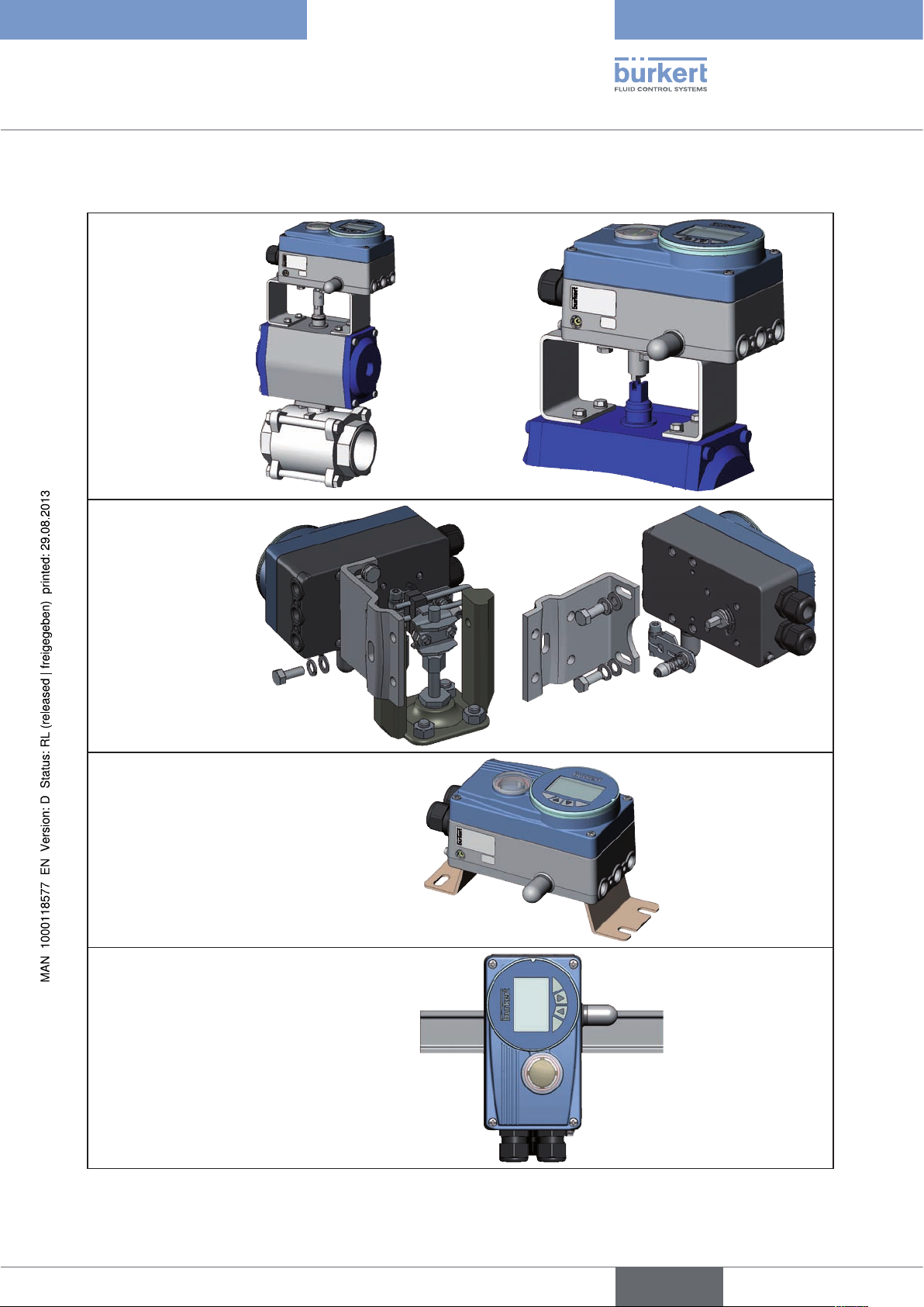
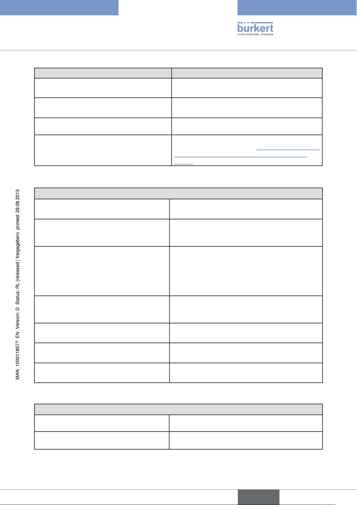
6.1.3. Overview of the mounting options
Mounting on
rotary actuator
Mounting with
mounting bracket
on a linear actuator
Remote mounting
with mounting bracket
Remote mounting
with DIN rail
Table 1: Overview of the mounting options
15
English
Page 16

Types 8792, 8793
Description of System
6.2. Designs
6.2.1. Type 8792, positioner
The position of the actuator is regulated according to the position set-point value. The position set-point value is
specified by an external standard signal (or via field bus).
6.2.2. Type 8793, process controller
Type 8793 also features a PID controller which, apart from actual position control, can also be used to implement
process control (e.g. level, pressure, flow rate, temperature) in the sense of a cascade control.
The process controller Type 8793 is operated with a 128 x 64 dot matrix graphics display and a keypad with 4
keys.
The process controller is linked to a control circuit. The position set-point value of the valve is calculated from the
process set-point value and the actual process value via the control parameters (PID controller). The process setpoint value can be set by an external signal.
16
English
Page 17
Types 8792, 8793
Description of System
7. STRUCTURE
The positioner Type 8792 and process controller Type 8793 consist of the micro-processor controlled electronics,
the position sensor and the control system.
The device is designed using three-wire technology. Operation is controlled by four keys and a 128x64 dot matrix
graphics display.
The pneumatic control system for single-acting and double-acting actuators consists of 2 solenoid valves.
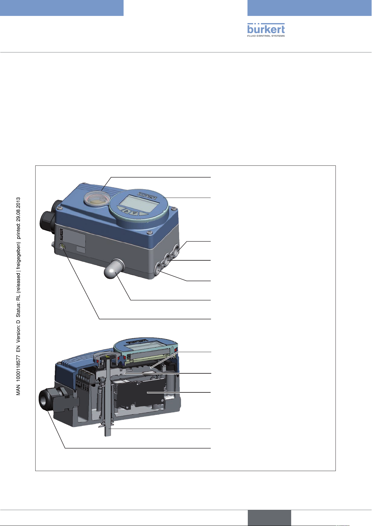
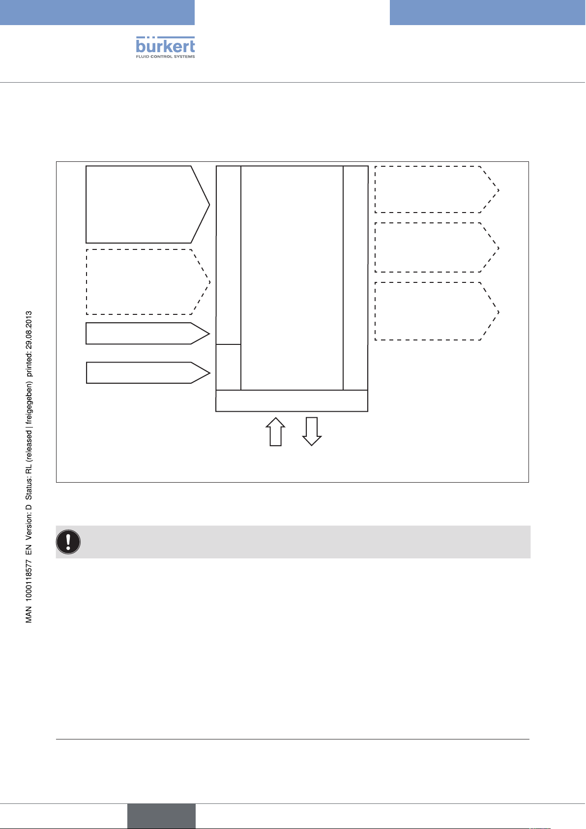
7.1. Representation
Mechanical position indicator
Operating module with display and keys
Working connection 2
(connection: A2)
Supply pressure connection 1.4 – 7 bar
(connection: P)
Working connection 1
(connection: A1)
Air exhaust connection/air exhaust filter
Pressure-relief valve
Electronic module
Internal position sensor
Control system
Figure 1: Structure, Type 8792 / 8793
Shaft for position sensor
Cable gland
17
English
Page 18
Types 8792, 8793
Description of System
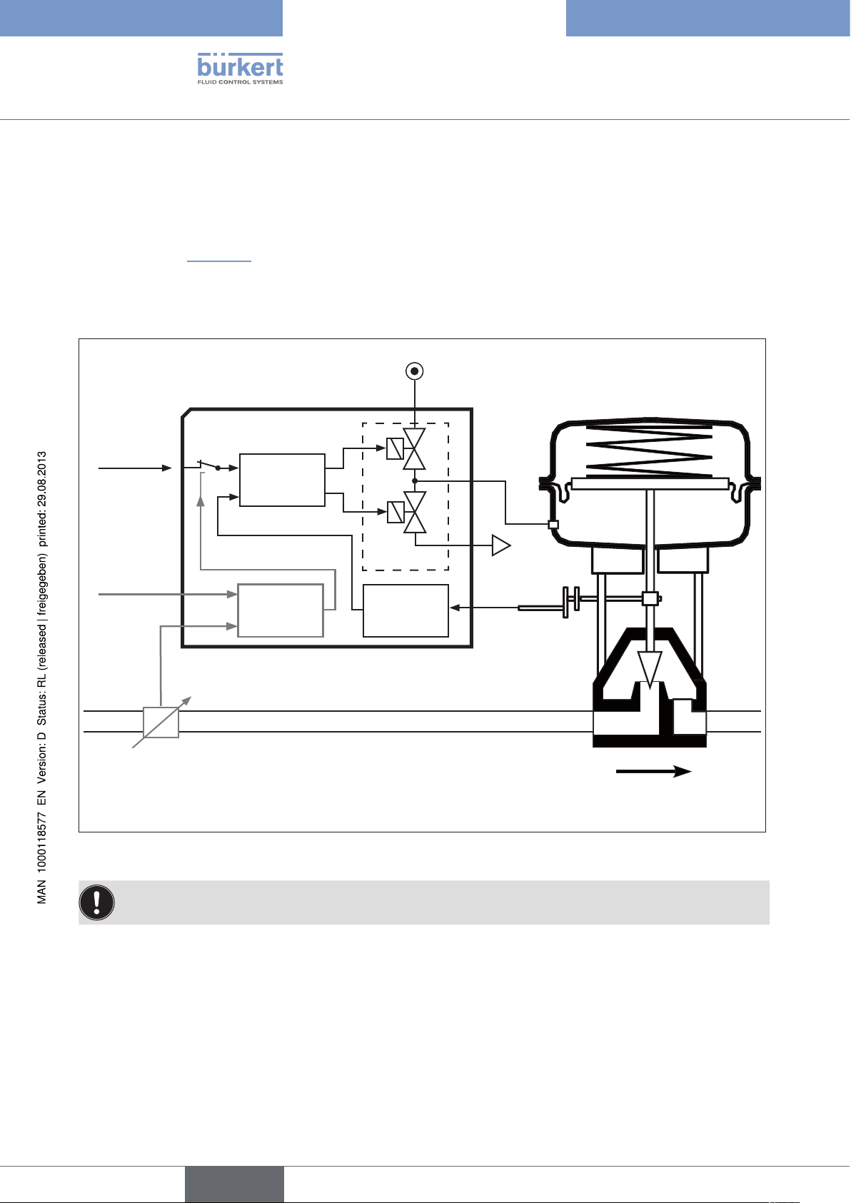
7.2. Function diagram
7.2.1. Diagram illustrating single-acting actuator
The black lines in “Figure 2” specify the function of the position controller circuit in Type 8792.
The grey part of the diagram indicates the additional function of the superimposed process control circuit in Type
8793.
Compressed-
Type 8792 / 8793
air supply
Continuous valve with
single-acting actuator
Position setpoint value
Process
set-point
value
Process
actual
value
Sensor
Positioner
Actual position
Nominal position
Process
controller
1
2
Control
system*
Position
sensor
* Control system
1: Aeration valve
2: Bleed valve
Exhaust air
18
Figure 2: Structure, positioner Type 8792 / process controller 8793
The remote design has the position sensor situated outside the device directly on the continuous valve
and is connected to the latter by a cable.
English
Page 19
Types 8792, 8793
Description of System
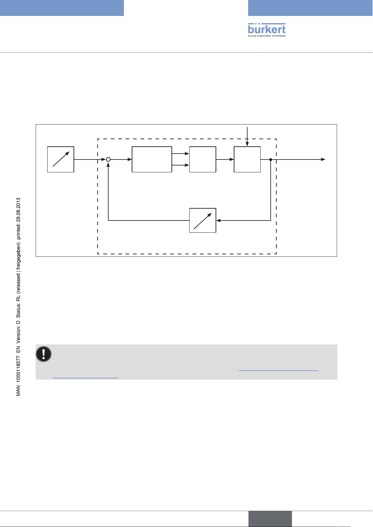
8. POSITIONER TYPE 8792
The position sensor records the current position (POS) of the pneumatic actuator. The positioner compares this
actual position value with the set-point value (CMD) which is specified as a standard signal. If there is a control difference (Xd1), the actuator is aerated and deaerated via the control system. In this way the position of the actuator
is changed until control difference is 0. Z1 represents a disturbance variable.
Z1
CMD Xd1
+
-
PositionerPosition set-
point value
Position control circuit
Figure 3: Position control circuit in Type 8792
B1
E1
POS
P
K
Control system
Solenoid valves
Position sensor
Valve opening
Continuous
valve
8.1. Positioner (position controller) Type 8793 Remote
with external position sensor
In the case of this model, Type 8793 has no position sensor in the form of a rotary position sensor, but an external
path sensor.
By connecting the path sensor to the analog interface (4... 20 mA), Type 8793 can be operated only as a
positioner (position controller).
The options for connection of a path sensor are described in Chapter “12.4. Remote operation with
external position sensor”.
English
19
Page 20
Types 8792, 8793
Description of System
8.2. Schematic representation of the position control
POS
CMD
TEMP
INPUT
X.CONTROL
DBND
POS
CMD
DIR.ACT X.LIMIT
20
4 – 20 mA
0 – 20 mA
0 – 10 V
Figure 4: Schematic representation of position control
English
0 – 5 V
DIR.CMD SPLTRNG CHARACT CUTOFF X.TIME
INP
Page 21
Types 8792, 8793
Description of System
8.3. Positioner software
Configurable auxiliary functions Effect
Correction line to adjust the operating characteristic
CHARACT
Sealing function
CUTOFF
Sense of effective direction of the controller setpoint value
DIR.CMD
Sense of effective direction of the actuator
DIR.ACT
Signal range splitting
SPLTRNG
Stroke limit
X.LIMIT
Limiting the control speed
X.TIME
Insensitivity range
X.CONTROL
Code protection
Selection of the transfer characteristic between
input signal and stroke (correction characteristic)
Valve closes tight outside the control range. Specification
of the value (in %), from which the actuator is completely
deaerated (when 0%) or aerated (when 100%).
Reversal of the sense of effective direction of the setpoint value
Adjustment of the sense of effective direction between
aeration state of the actuator and the actual position
Splitting of the standard signal range to two or more
positioners
Mechanical valve piston movement only within a defined
stroke range
Input of the opening and closing time for the entire stroke
The positioner is initially actuated from a control difference to be defined
Code protection for settings
SECURITY
Safety position
SAFEPOS
Signal level error detection
SIG.ERROR
Binary input
BINARY. IN
Analogue feedback (option)
OUTPUT
2 binary outputs (option)
OUTPUT
User calibration
CAL.USER
Factory settings
SET.FACTORY
Serial interface
SER.I/O
Definition of the safety position
Check the input signals for sensor break.
Warning output on the display and start up of the safety
position (if selected)
Switch over AUTOMATIC / MANUAL or
Start up of the safety position
Status signal set-point value or actual value
Output of two selectable binary values
Change to the factory calibration of the signal input
Reset to factory settings
Configuration of serial interface
21
English
Page 22
Configurable auxiliary functions Effect
Types 8792, 8793
Description of System
Setting display
Adjustment of the display of the process level
EXTRAS
SERVICE
POS.SENSOR
For internal use only
Setting interface remote path sensor (available for Type
8793 Remote only. See chapter “8.1. Positioner (position
controller) Type 8793 Remote with external position
sensor”.
Simulation software
For simulation of the device functions
SIMULATION
DIAGNOSE (Option)
Table 2: Positioner software. Configurable auxiliary functions
Monitoring of processes
Hierarchical operating concept for easy operation on the following operating levels
Process level On the process level switch between AUTOMATIC mode
and MANUAL mode.
Setting level On the setting level specify certain basic functions during
start-up and, if required, configure additional functions
Table 3: The positioner software. Hierarchical operating concept.
22
English
Page 23

Types 8792, 8793
Description of System
9. PROCESS CONTROLLER TYPE 8793
In the case of process controller Type 8793 the position control mentioned in Chapter “8” becomes the subordinate auxiliary control circuit; this results in a cascade control. The process controller in the main control circuit of
Type 8793 has a PID function. The process set-point value (SP) is specified as set-point value and compared with
the actual value (PV) of the process variable to be controlled. The position sensor records the current position (POS)
of the pneumatic actuator. The positioner compares this actual position value with the set-point value (CMD), which
is determined by the process controller. If there is a control difference (Xd1), the actuator is aerated and deaerated
via the control system. In this way the position of the actuator is changed until control difference is 0. Z2 represents
a disturbance variable.
Z1
CMD
SP
Process setpoint value
Xd1
+
-
Positioner
B1
E1
Control system
Solenoid valves
P
K
Continuous
valve
Valve opening
POS
Position sensor
Position control circuit
Z2
Xd2
+
-
CMD
Position
control
circuit
Process
Valve
opening
Process
Process variable
controller
PV
Figure 5: Signal flow plan of process controller
Transmitter
23
English
Page 24
Types 8792, 8793
Description of System
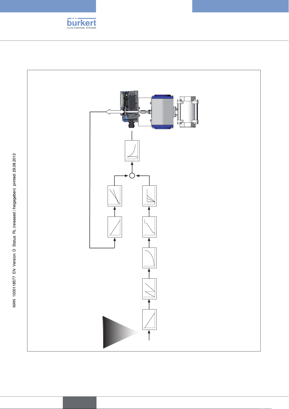
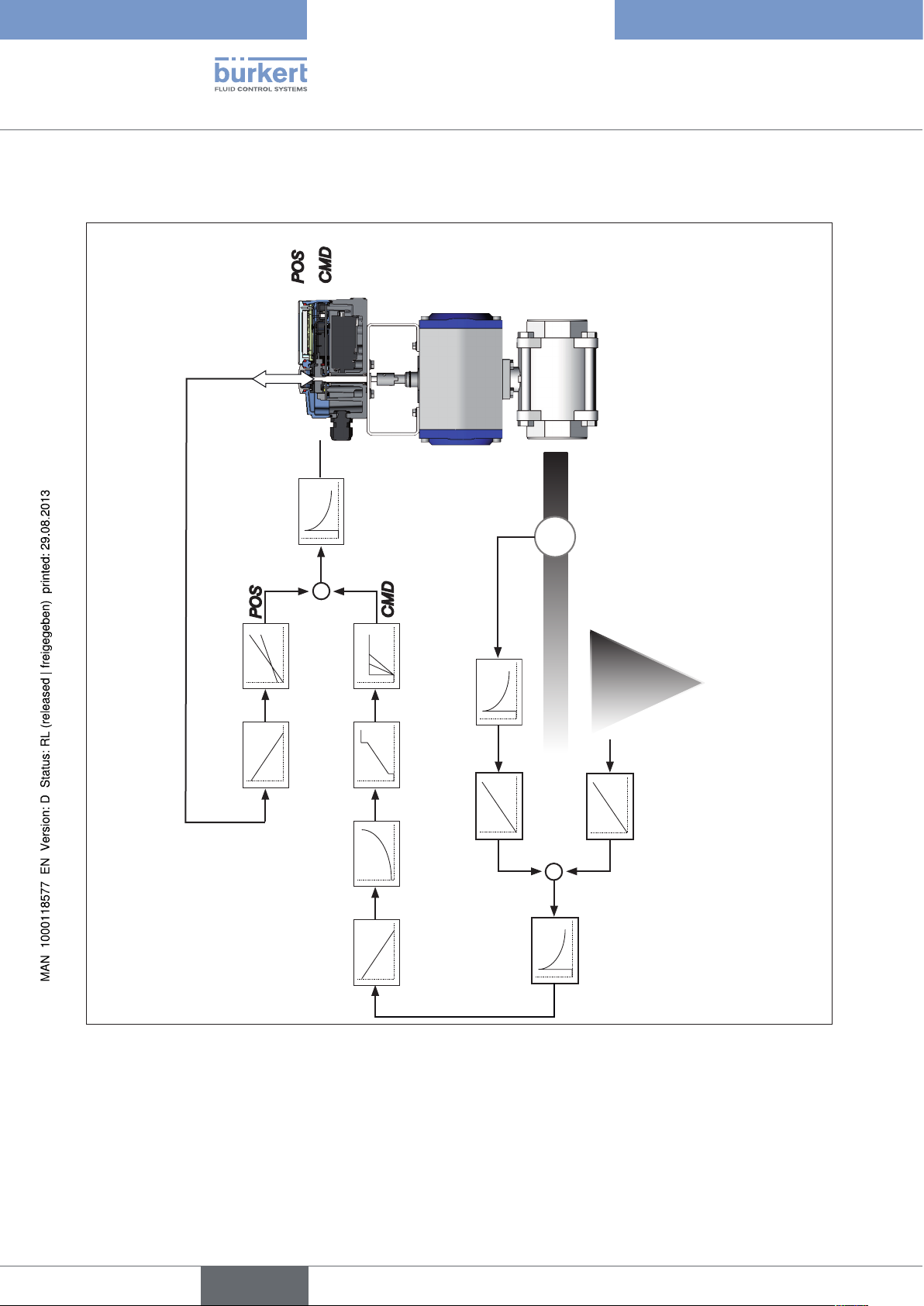
9.1. Schematic representation of process control
POS
CMDPVSP
TEMP
POS
-
DIR.ACT X.LIMIT
X.CONTROL
DBDx
+
CMD
PV SCALE
DIR.CMD CHARACT CUTOFF X.TIME
FILTER
PV
PV
Q
4 – 20 mA
0 – 20 mA
0 – 10 V
0 – 5 V
SP SCALE
SP
-
+
SP
P.CONTROL
PARAMETER
SETUP
24
Figure 6: Schematic representation of process control
English
Page 25
Types 8792, 8793
Description of System
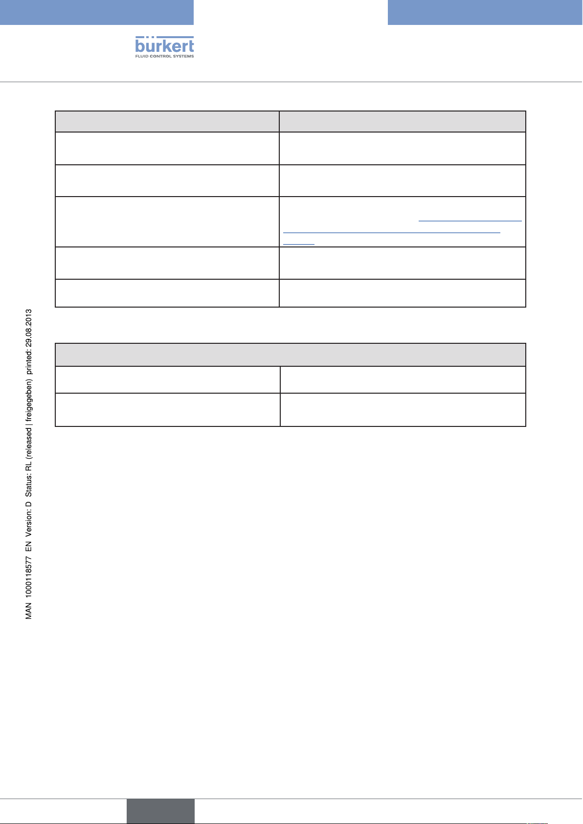
9.2. Type 8793 remote operation with external position sensor
In the case of this model the positioner has no position sensor in the form of a rotary position sensor, but an
external remote sensor.
Depending on the connection type of the path sensor, Type 8793 functions as a
• Process controller or
• Positioner (position controller)
The following connection options are possible:
Function
Interface sensor Setting in the menu (ADD.FUNCTION)
Type 8793
Process controller digital (serial) Remote Sensor Type 8798
POS.SENSOR → DIGITAL
For menu description see Chapter
“26.2.19”
Positioner
(position controller)
analog
(4 ... 20 mA) *
Any, high-resolution path
sensor
POS.SENSOR → ANALOG
For menu description see Chapter
“26.2.19”
Table 4: Connection options type 8793 with external position sensor
* If the path sensor is connected to the process controller Type 8793 via the analog interface, it can be
operated only as a positioner (position controller).
English
25
Page 26
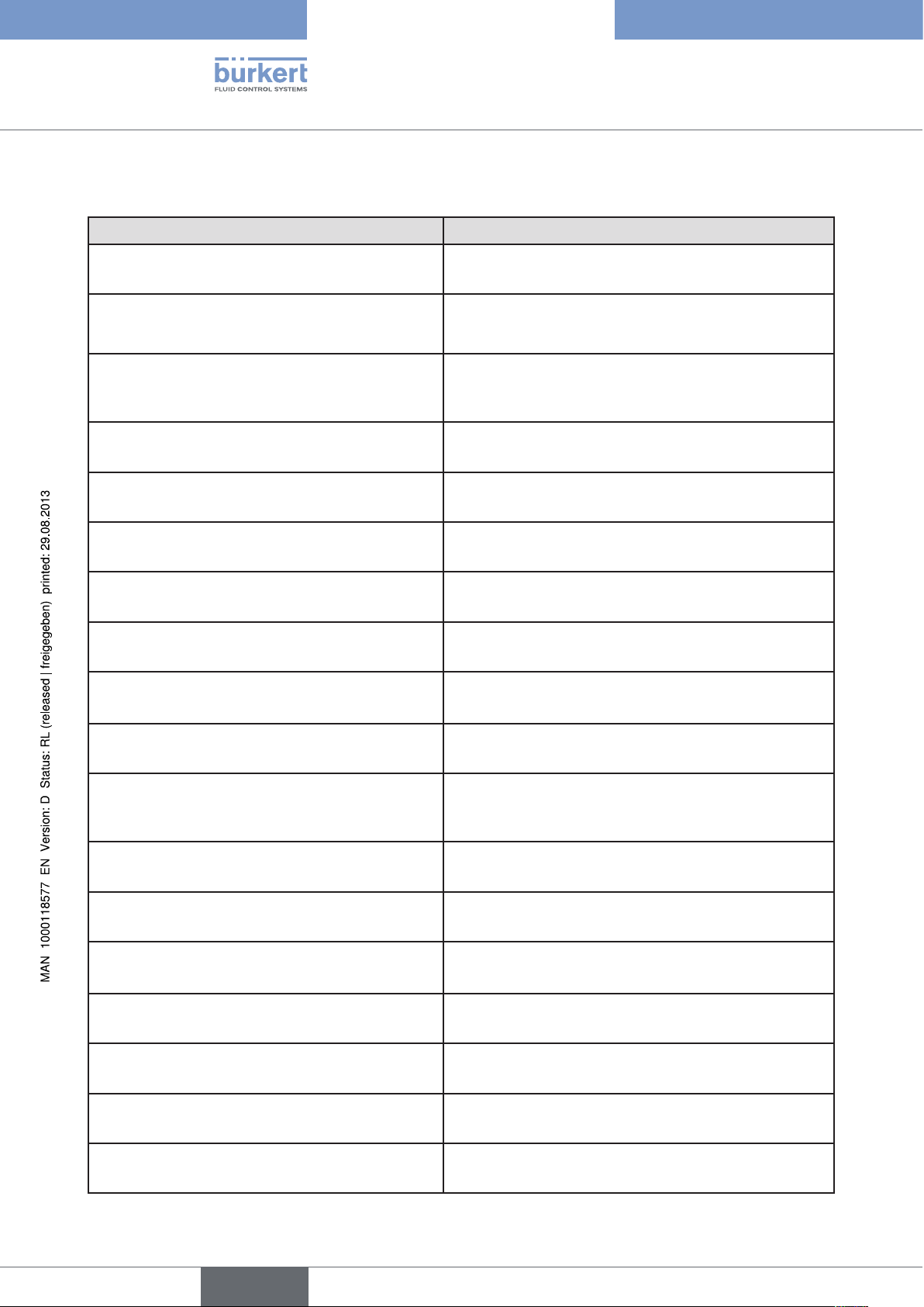
9.3. The process controller software
Configurable auxiliary functions Effect
Correction line to adjust the operating characteristic
CHARACT
Sealing function
CUTOFF
Sense of effective direction of the controller setpoint value
DIR.CMD
Sense of effective direction of the actuator
DIR.ACT
Signal range splitting
SPLTRNG
Stroke limit
X.LIMIT
Limiting the control speed
Selection of the transfer characteristic between
input signal and stroke (correction characteristic)
Valve closes tight outside the control range. Specification
of the value (in %), from which the actuator is completely
deaerated (when 0%) or aerated (when 100%).
Reversal of the sense of effective direction of the setpoint value
Adjustment of the sense of effective direction between
aeration state of the actuator and the actual position
Splitting of the standard signal range to two or more
positioners
Mechanical valve piston movement only within a defined
stroke range
Input of the opening and closing time for the entire stroke
Types 8792, 8793
Description of System
X.TIME
Insensitivity range
X.CONTROL
Code protection
SECURITY
Safety position
SAFEPOS
Signal level error detection
SIG.ERROR
Binary input
BINARY. IN
Analogue feedback (option)
OUTPUT
2 binary outputs (option)
OUTPUT
User calibration
CAL.USER
Factory settings
The positioner is initially actuated from a control difference to be defined
Code protection for settings
Definition of the safety position
Check the input signals for sensor break.
Warning output on the display and start up of the safety
position (if selected)
Switch over AUTOMATIC / MANUAL or
Start up of the safety position
Status signal set-point or actual value
Output of two selectable binary values
Change to the factory calibration of the signal input
Reset to factory settings
26
SET.FACTORY
Serial interface
SER.I/O
Setting display
EXTRAS
Configuration of serial interface
Adjustment of the display of the process level
English
Page 27
Types 8792, 8793
Description of System
Configurable auxiliary functions Effect
SERVICE
For internal use only
Simulation software
For simulation of the device functions
SIMULATION
DIAGNOSE (Option)
POS.SENSOR
Monitoring of processes
Setting interface remote path sensor (available for Type
8793 Remote only. See chapter “8.1. Positioner (position
controller) Type 8793 Remote with external position
sensor”.
Table 5: The process controller software. Configurable auxiliary functions of the position controller
Functions and setting options of the process controller
Process controller
PID - Process controller is activated
P.CONTROL
Adjustable parameters
P.CONTROL - PARAMETER
Parameterization of the process controller
Proportional coefficient, reset time, hold-back time and
operating point
Scalable inputs
P.CONTROL - SETUP
Configuration of the process controller
- Selection of the sensor input
- Scaling of process actual value and process set-point
value
Selection of the set-point value defaults
Automatic sensor detection or manual sensor
setting
Sensor types Pt100 and 4 – 20 mA are automatically
detected or can be set manually via the operating menu
P.CONTROL - SETUP - PV INPUT
Selection of the set-point value specification
P.CONTROL - SETUP - SP INPUT
Process characteristic linearization
P.Q‘LIN
Process controller optimization
P.TUNE
Table 6: The process controller software. Functions and setting options of the process controller
Set-point value specification either via standard signal
input or via keys
Function for automatic linearization of the process
characteristics
Function for automatic optimization of the process controller parameters
Hierarchical operating concept for easy operation on the following operating levels
Process level On the process level switch between AUTOMATIC and
MANUAL mode.
Setting level On the setting level specify certain basic functions during
start-up and configure auxiliary functions if required.
Table 7: The process controller software. Hierarchical operating concept
27
English
Page 28
Types 8792, 8793
Description of System
10. INTERFACES OF THE POSITIONER / PROCESS CONTROLLER
Inputs for position or
process set-point value
4 – 20 mA
0 – 20 mA
0 – 10 V
0 – 5 V
Input for process
actual value*
4 – 20 mA
frequency
Pt 100
Binary input
24 V DC
Note:
Optional inputs and outputs are illustrated by dotted lines
Positioner /
Process controller
Inputs
Supply
Operation
2 binary outputs
24 V PNP
Initiator 1 / Initiator 2
24 V PNP NO
Outputs
Analogue feedback
4 – 20 mA
0 – 10 V
28
Figure 7: Interfaces of the positioner / process controller
The Types 8792 and 8793 are 3-wire devices, i.e. the power (24 V DC) is supplied separately from the
set-point value signal.
* only for process controller Type 8793
English
Page 29
Types 8792, 8793
Description of System
11. TECHNICAL DATA
11.1. Conformity
In accordance with the Declaration of conformity, Type 8792 / 8793 is compliant with the EC Directives.
11.2. Standards
The applied standards which are used to demonstrate compliance with the EC Directives are listed in the
EC-Type Examination Certificate and/or the EC Declaration of Conformity.
11.3. Operating conditions
NOTE!
If used outside, the device may be exposed to direct sunlight and temperature fluctuations which may
cause malfunctions or leaks!
• If the device is used outdoors, do not expose it unprotected to the weather conditions.
• Ensure that the permitted ambient temperature does not exceed the maximum value or drop below the minimum value.
Environmental temperature 0 – +60 °C
Degree of protection IP 65 / IP 67* according to EN 60529
(only if cables, plugs and sockets have been connected correctly)
* If the device is used under IP 67 conditions, the ventilation filter (see
“Figure 1: Structure, Type 8792 / 8793” must be removed and the exhaust
air conducted into the dry area.
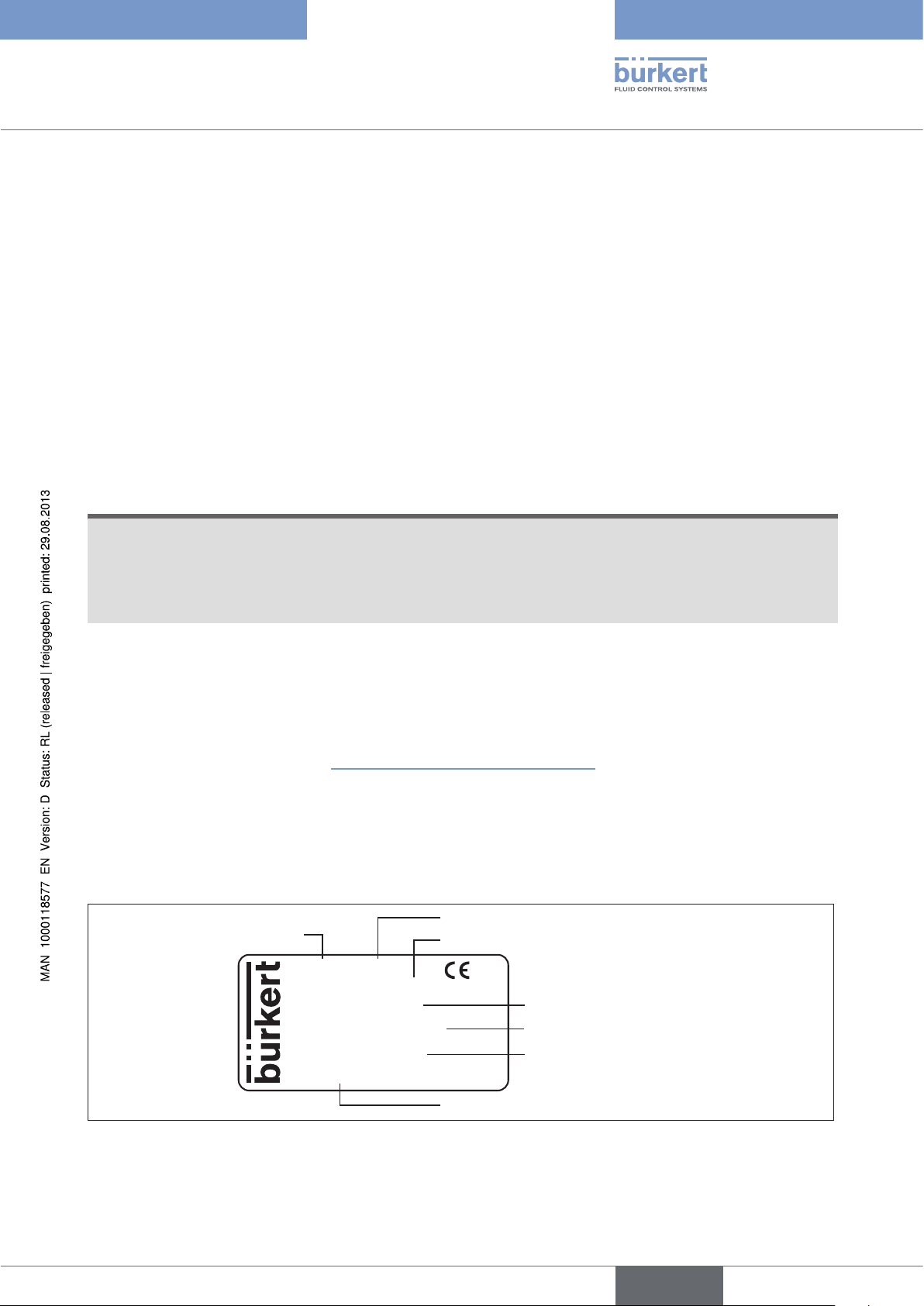
11.4. Rating plate and additional plate for Ex devices
Explanation of the device-specific specifications on the rating plate:
Operating voltage / controlExample:
Type
8792 24V / DC
Remote IP65/IP67
P = 1,4 ... 7 bar
Tamb 0°C...+60°C
Ser.-Nr.: 001000
00177689 W12LL
D-74653 Ingelfingen
Degree of protection
Nominal pressure
Ambient temperature
Serial number
Figure 8: Example of rating plate
Identification number
29
English
Page 30
Types 8792, 8793
Description of System
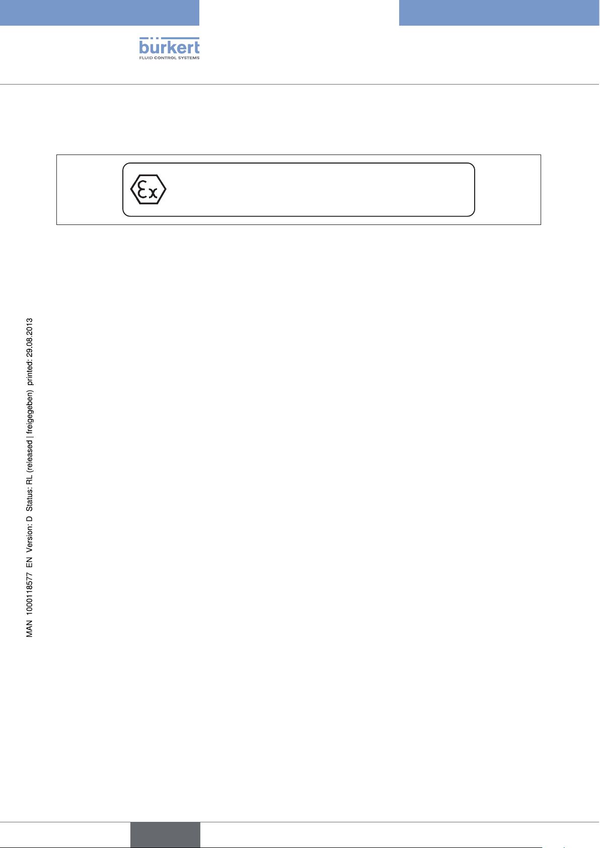
Additional plate for Ex devices:
Devices, which may be used in the explosion-protected area, are identified by the additional plate for Ex devices.
1. Do not open under
II 3 G Ex nA IIC T4
II 3 D Ex tD A22 T135°C
Figure 9: Additional plate for Ex devices
explosive atmosphere
2. In Hazardous Areas the surface
Warning:
may only be cleaned with a wet towel
11.5. Mechanical data
Dimensions See data sheet
Material
Housing material Plastic-coated aluminium
Other external parts Stainless steel (V4A), PC, PE, POM, PTFE
Sealing material EPDM, NBR, FKM
Mass approx. 1.0 kg
30
English
Page 31

Types 8792, 8793
Description of System
11.6. Electrical data
Connections 2 cable glands (M20 x 1.5) with screw-type terminals 0.14 – 1.5 mm2 or
circular plug-in connector
Operating voltage 24 V DC ± 10% max. residual ripple 10%
Power consumption < 5 W
Input data for actual value signal
4 – 20 mA: Input resistance 180 Ω
Resolution 12 bit
Frequency: Measuring range 0 – 1000 Hz
Input resistance 17 kΩ
Resolution 1‰ of the measured value,
Input signal > 300 mVss
Signal form Sine, rectangle, triangle
Pt 100 Measuring range -20 – +220 °C,
Resolution < 0.1 °C,
Measurement current < 1 mA
Input data for set-point value signal
0/4 – 20 mA: Input resistance 180 Ω
Resolution 12 bit
0 – 5/10 V: Input resistance 19 kΩ
Resolution 12 bit
Protection class 3 in accordance with VDE 0580
Analogue feedback
max. current 10 mA (for voltage output 0 – 5/10 V)
Burden (load) 0 – 560 Ω (for current output 0/4 – 20 mA)
Inductive proximity switches 100 mA current limit
Binary outputs galvanically isolated
Current limiting 100 mA, output is clocked if overload occurs
Binary input galvanically isolated
0 – 5 V = log “0”, 10 – 30 V = log “1”
inverted input in reverse order (input current < 6 mA)
English
31
Page 32

Types 8792, 8793
Description of System
11.7. Pneumatic data
Control medium Quality classes in accordance with DIN ISO 8573-1
Dust content Class 5, max. particle size 40 µm, max. particle density 10 mg/m³
Water content Class 3, max. pressure dew point - 20 °C or min. 10 degrees below the
lowest operating temperature
Oil content Class 5, max. 25 mg/m³
Temperature range of compressed air 0 – +60 °C
Pressure range 1.4 – 7 bar
Air flow rate 95 lN / min (at 1.4 bar*) for aeration and deaeration
150 lN / min (at 6 bar*) for aeration and deaeration
(QNn = 100 lN / min (according to definition for pressure drop from 7 to
6 bar absolute)).
Connections Internal thread G1/4“
32
* Pressure specifications: Overpressure with respect to atmospheric pressure
English
Page 33

Types 8792, 8793
Description of System
11.8. Safety end positions after failure of the electrical or pneumatic auxiliary power
The safety end position depends on the fluidic connection of the actuator to the working connections A1 or A2.
Safety end positions after failure of the
Actuator system Designation
single-acting
up
down
up
down
Control function
A
single-acting
control function
B
electrical auxiliary power
down
→ Connection according to “Figure 10”
up
→ Connection according to “Figure 11”
up
→ Connection according to
down
“Figure 10”
→ Connection according to “Figure 11”
pneumatic
auxiliary power
down
up
upper
chamber
double-acting
lower
chamber
Table 8: Safety end position
Fluid connection: Description for “Table 8”
Connection:
working connection A1 to actuator
A2 sealing
up
down
Control function
I
Single-acting actuators
Control function A and B
Connection:
working connection A2 to actuator
A1 sealing
Fluid connection see “Figure 12”
up = lower chamber of the actuator to A2
down = upper chamber of the actuator to A2
Double-acting actuators
Control function I
Connection:
Working connection A1 and A2
to actuator
Safety end position:
up = lower chamber to A2
down = upper chamber to A2
not defined
Figure 10: Connection A1 Figure 11: Connection A2 Figure 12: Connection with CFI
English
33
Page 34

Types 8792, 8793
Description of System
11.9. Factory settings
The factory settings can be found in Chapter “27. Operating structure and factory settings”, page 174.
The factory presets are highlighted in blue to the right of the menu in the operating structure.
Examples:
Representation Description
Menu options activated or selected at the factory
Menu options not activated or selected at the factory
2.0 %
10.0 sec /....
Table 9: Illustration of the factory settings
Values set at the factory
34
English
Page 35

Type 8792, 8793
Installation
conTenTs
12. ATTACHMENT AND ASSEMBLY ................................................................................................................................................37
Safety instructions: ............................................................................................................................................................37
12.1.
Attachment to a continuous valve with linear actuators according to NAMUR ................................38
12.2.
12.2.1. Attachment kit for linear actuators (serial no. 787 215) .........................................................38
12.2.2. Installation .......................................................................................................................................... 39
12.2.3. Attaching mounting bracket ..........................................................................................................41
12.2.4. Aligning lever mechanism ..............................................................................................................42
Attachment to a continuous valve with rotary actuator .................................................................................43
12.3.
12.3.1. Mounting kit (VDI/VDE 3845) on rotary actuator (part no. 787338)...................................43
12.3.2. Installation .......................................................................................................................................... 43
Remote operation with external position sensor ..............................................................................................46
12.4.
12.4.1. Mounting accessories .....................................................................................................................46
12.4.2. Connection and start-up of the Remote Sensor Type 8798 .................................................47
12.4.3. Connection and start-up via a 4 – 20 mA path sensor
(for Type 8793 remote model only) .............................................................................................48
FLUID CONNECTION ......................................................................................................................................................................49
13.
Safety instructions .............................................................................................................................................................49
13.1.
ELECTRICAL CONNECTION -
14.
CIRCULAR PLUG-IN CONNECTOR VERSION (MULTI-POLE VERSION) ............................................................. 51
Type 8792 - designation of the circular plug-in connectors ........................................................................52
14.1.
Connection of the positioner Type 8792 ................................................................................................................52
14.2.
14.2.1. X1 - M12, 8-pole circular connector .........................................................................................52
14.2.2. X4 - M8, 4-pole socket (for binary outputs option only)
Output signals to the control centre (e.g. PLC)........................................................................53
Type 8793 - designation of the circular plug-in connectors and contacts ..........................................54
14.3.
Connecting the process controller Type 8793 ....................................................................................................55
14.4.
14.4.1. X5 - M8, 4-pole circular connector,
plug assignments of the process actual value input ...............................................................55
english
35
Page 36

Type 8792, 8793
Installation
15. ELECTRICAL CONNECTION - TERMINAL VERSION FOR CABLE GLAND ........................................................56
Connection board of the Type 8792/8793 with screw-type terminals ...................................................57
15.1.
Terminal assignment for cable gland - positioner Type 8792 ....................................................................57
15.2.
15.2.1. Input signals from the control centre (e.g. PLC) .......................................................................57
15.2.2. Output signals to the control centre (e.g. PLC)
(required for analogue output and/or binary output option only) ..........................................58
15.2.3. Operating voltage ............................................................................................................................58
15.2.4. Terminal assignment for external position sensor (for remote model only).........................58
Terminal assignment for cable gland - process controller Type 8793 ...................................................59
15.3.
15.3.1. Terminal assignments of the process actual value input ........................................................ 59
36
english
Page 37

Type 8792, 8793
Installation
12. ATTACHMENT AND ASSEMBLY
The dimensions of the Type 8792/8793 and the different device versions can be found on the data sheet.
12.1. Safety instructions:
WARNING!
Risk of injury from improper installation!
• Installation may be carried out by authorised technicians only and with the appropriate tools!
Risk of injury from unintentional activation of the system and an uncontrolled restart!
• Secure system from unintentional activation.
• Following assembly, ensure a controlled restart.
english
37
Page 38

Type 8792, 8793
Installation
12.2. Attachment to a continuous valve with linear actuators according to NAMUR
The valve position is transferred to the position sensor installed in the positioner via a lever (according to
NAMUR).
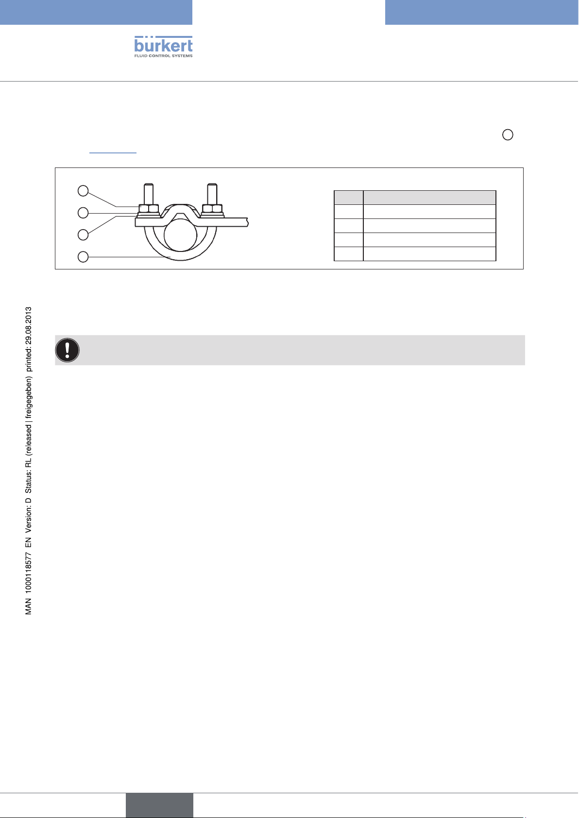
12.2.1. Attachment kit for linear actuators (serial no. 787 215)
(Can be purchased as an accessory from Bürkert).
Part no. Quantity Name
1 1 NAMUR mounting bracket IEC 534
2 1 Hoop
3 2 Clamping piece
4 1 Driver pin
5 1 Conical roller
6a 1 NAMUR lever for stroke range 3 – 35 mm
6b 1 NAMUR lever for stroke range 35 – 130 mm
7 2 U-bolt
8 4 Hexagon bolt DIN 933 M8 x 20
9 2 Hexagon bolt DIN 933 M8 x 16
10 6 Circlip DIN 127 A8
11 6 Washer DIN 125 B8.4
12 2 Washer DIN 125 B6.4
13 1 Spring VD-115E 0.70 x 11.3 x 32.7 x 3.5
14 1 Spring washer DIN 137 A6
15 1 Locking washer DIN 6799 - 3.2
16 3 Circlip DIN 127 A6
17 3 Hexagon bolt DIN 933 M6 x 25
18 1 Hexagon nut DIN 934 M6
19 1 Square nut DIN 557 M6
21 4 Hexagon nut DIN 934 M8
22 1 Guide washer 6.2 x 9.9 x 15 x 3.5
38
Table 10: Attachment kit for linear actuators
english
Page 39

Type 8792, 8793
Installation
12.2.2. Installation
WARNING!
Risk of injury from improper installation!
• Installation may be carried out by authorised technicians only and with the appropriate tools!
Risk of injury from unintentional activation of the system and an uncontrolled restart!
• Secure system from unintentional activation.
• Following assembly, ensure a controlled restart.
Procedure:
→ Using the clamping pieces ③, hexagon bolts ⑰ and circlips ⑯ attach the hoop ② to the actuator spindle.
2
Legend:
No. Name
16
2 Hoop
3 Clamping piece
16 Circlip
17 Hexagon bolt
3
17
Figure 13: Attaching the hoop
→ Select short or long lever according to the stroke of the actuator. (see “Table 10: Attachment kit for linear
actuators”).
→ Assemble lever (if not pre-assembled) (see “Figure 14”).
english
39
Page 40

Type 8792, 8793
Installation
17
Legend:
No. Name
4 Driver pin
16
12
6
19
22
13
4
15
Figure 14: Assembling the lever
5
18
14
12
5 Conical roller
6 Lever
12
13
14
For a description of
15
the numbering,
16
refer to
“Table 10: Attachment
17
kit for linear actuators”
18
19
22
The gap between the driver pin and the shaft should be the same as the drive stroke. As a result, the lever
has a swing range of 60°. (see “Figure 15”).
Rotation range of the position sensor:
The maximum rotation range of the position sensor is 180°.
Swing range of the lever:
To ensure that the position sensor operates at a good resolution, the swing range of the lever must be at
least 30°.
The swing movement of the lever must be within the position sensor rotation range of 180°.
The scale printed on the lever is not relevant.
180°
Maximum swing
range of the lever
The swing movement of the lever must be
60°
of the lever
within the position sensor rotation range of
180°.
Ideal swing range
(min. 30 ° / max. 180 °).
40
Figure 15: Swing range of the lever
→ Attach lever to the shaft of the Type 8792/8793 and screw tight.
english
Page 41

Type 8792, 8793
Installation
12.2.3. Attaching mounting bracket
→ Attach mounting bracket ① to the back of the Type 8792/8793 with hexagon bolts ⑨, circlip ⑩ and
washers ⑪ (see “Figure 16”).
The selection of the M8 thread used on the Type 8792/8793 depends on the size of the actuator.
→ To determine the correct position, hold the Type 8792/8793 with mounting bracket on the actuator.
The conical roller ⑤ on the lever ⑥ of the position sensor must be able to move freely in the hoop (refer
“Figure 16”) along the entire stroke range of the actuator.
At 50% stroke the lever position should be approximately horizontal (see chapter “12.2.4. Aligning lever
mechanism”.
M8 thread
Legend:
⑨
No. Name
1 Mounting bracket
5 Conical roller
6 Lever
9 Hexagon bolt
10 Circlip
11 Washer
⑥⑤
①
⑩
Figure 16: Attaching mounting bracket
Attaching the Type 8792/8793 with mounting bracket for actuators with cast frame:
→ Attach mounting bracket to the cast frame with one or more hexagon bolts ⑧, washers ⑪ and circlips ⑩
(see “Figure 17”).
⑪
8
10
11
Legend:
No. Name
1 Mounting bracket
8 Hexagon bolt
10
11
8
Figure 17: Attach Type 8792/8793 with mounting bracket; for actuators with cast frame
1
10 Circlip
11 Washer
41
english
Page 42
Type 8792, 8793
Installation
Attaching the Type 8792/8793 with mounting bracket for actuators with columnar yoke:
→ Attach mounting bracket to the columnar yoke with the U-bolt ⑦, washers ⑪, circlips ⑩ and hexagon nuts
(see “Figure 18”).
Legend:
21
10
11
7
Figure 18: Attach Type 8792/8793 with mounting bracket; for actuators with columnar yoke
No. Name
7 U-bolt
10 Circlip
11 Washer
21 Hexagon nut
12.2.4. Aligning lever mechanism
The lever mechanism cannot be correctly aligned until the device has been connected electrically and
pneumatically.
→ Move the actuator in manual mode to half stroke (according to the scale on the actuator).
→ Adjust the height of the Type 8792/8793 until the lever is horizontal.
21
→ Fix the Type 8792/8793 in this position on the actuator.
42
english
Page 43

Type 8792, 8793
Installation
12.3. Attachment to a continuous valve with rotary actuator
The shaft of the position sensor integrated in the positioner is connected directly to the shaft of the rotary
actuator.
12.3.1. Mounting kit (VDI/VDE 3845) on rotary actuator (part no. 787338)
(Can be purchased as an accessory from Bürkert).
Part no. Quantity Name
1 1 Adapter
2 2 Setscrew DIN 913 M4 x 10
3 4 Cheese-head screw DIN 933 M6 x 12
4 4 Circlip B6
5 2 Hexagon nut DIN985, M4
Table 11: Mounting kit on rotary actuator
Other accessories:
The order number for the assembly bridge with fastening screws (according to VDI/VDE 3845) can be found on
the data sheet for Type 8792/8793.
12.3.2. Installation
WARNING!
Risk of injury from improper installation!
• Installation may be carried out by authorised technicians only and with the appropriate tools!
Risk of injury from unintentional activation of the system and an uncontrolled restart!
• Secure system from unintentional activation.
• Following assembly, ensure a controlled restart.
Procedure:
→ Specify the attachment position of the Type 8792/8793:
- parallel to the actuator or
- rotated by 90° to the actuator.
→ Determine home position and direction of rotation of the actuator.
→ Connect adapter to the shaft of the Type 8792/8793 and secure with 2 setscrews.
english
43
Page 44

Type 8792, 8793
Installation
Anti-twist safeguard:
Note the flat side of the shaft!
One of the setscrews must be situated on the flat side of the shaft as an anti-twist safeguard
(see “Figure 19”).
Rotation range of the position sensor:
The maximum rotation range of the position sensor is 180°.
The shaft of the Type 8792/8793 may be moved within this range only.
180°
Maximum
swing range
The swing movement of the
flattened shaft must be within the
90°
Ideal position
for the swing range
of the flattened shaft
position sensor rotation range of
180°.
(min. 30 ° / max. 180 °).
Flattened shaft
Figure 19: Rotation range / anti-twist safeguard
→ Assemble the multi-part assembly bridge* suitable for the actuator.
→ Attach the assembly bridge to the Type 8792/8793 using 4 cheese-head screws ③ and circlips ④
(see “Figure 20”).
* The assembly bridge consists of
4 parts which can be adjusted
to the actuator by varying the
arrangement.
④
③
44
Figure 20: Attach assembly bridge (schematic representation)
english
Page 45

Type 8792, 8793
Installation
→ Place Type 8792/8793 with assembly bridge on the rotary actuator and attach (see “Figure 21”)
Figure 21: Rotary actuator attachment
If the X.TUNE ERROR 5 message is indicated on the graphics display after the X.TUNE function starts,
the shaft of the Type 8792/8793 is not correctly aligned with the shaft of the actuator
(see “Table 124: Error and warning message on X.TUNE”, page 231.
• Check alignment (as described previously in this chapter).
• Then repeat the X.TUNE function.
english
45
Page 46

Type 8792, 8793
Installation
12.4. Remote operation with external position sensor
In the case of this model, the positioner has no position sensor in the form of a rotary position sensor, but an
external path sensor.
Depending on the model of Type 8792/8793, there are the following connection options:
Device type Interface sensor Setting in the menu
(ADD.FUNCTION)
Type 8792 Remote digital (serial) Remote Sensor Type 8798
digital (serial) Remote Sensor Type 8798
Type 8793 Remote
Table 12: Connection options of path sensor
analog (4 ... 20 mA) *
Any, high-resolution path
sensor
–
POS.SENSOR → DIGITAL
For menu description see
“26.2.19”
POS.SENSOR → ANALOG
For menu description see
“26.2.19”
* If the path sensor is connected to the process controller Type 8793 via the analog interface, it can be
operated only as a positioner (position controller).
12.4.1. Mounting accessories
There are two options of attaching the Type 8792/8793 in remote operation (see “Figure 22”).
Installation on a DIN rail with accessory kit,
part no. 675702
Installation on a wall with accessory kit,
part no. 675715
46
Figure 22: Attachment types in remote operation
english
Page 47

Type 8792, 8793
Installation
12.4.2. Connection and start-up of the Remote Sensor Type 8798
WARNING!
Risk of injury from improper start-up!
• Start-up may be carried out by authorised technicians only and with the appropriate tools!
Risk of injury from unintentional activation of the system and an uncontrolled restart!
• Secure system from unintentional activation.
• Following assembly, ensure a controlled restart.
→ Connect the 3 or 4 wires of the sensor cable to the designated screw-type terminals of type 8792/8793.
Connection of screw-type terminals: See chapter “15.2.4. Terminal assignment for external position sensor
(for remote model only)”, page 58.
Connection of M8 circular connector (only for PROFIBUS and DeviceNet): See chapter PROFIBUS “29.5”,
page 195 / DeviceNet “32.5”, page 214.
→ Attach Remote Sensor on the actuator.
The correct procedure is described in the brief instructions for the Remote Sensor.
→ Connect compressed air to Type 8792/8793.
→ Connect Type 8792/8793 pneumatically to the actuator.
→ Switch on operating voltage to the Type 8792/8793.
→ Run the X.TUNE function.
english
47
Page 48

Type 8792, 8793
Installation
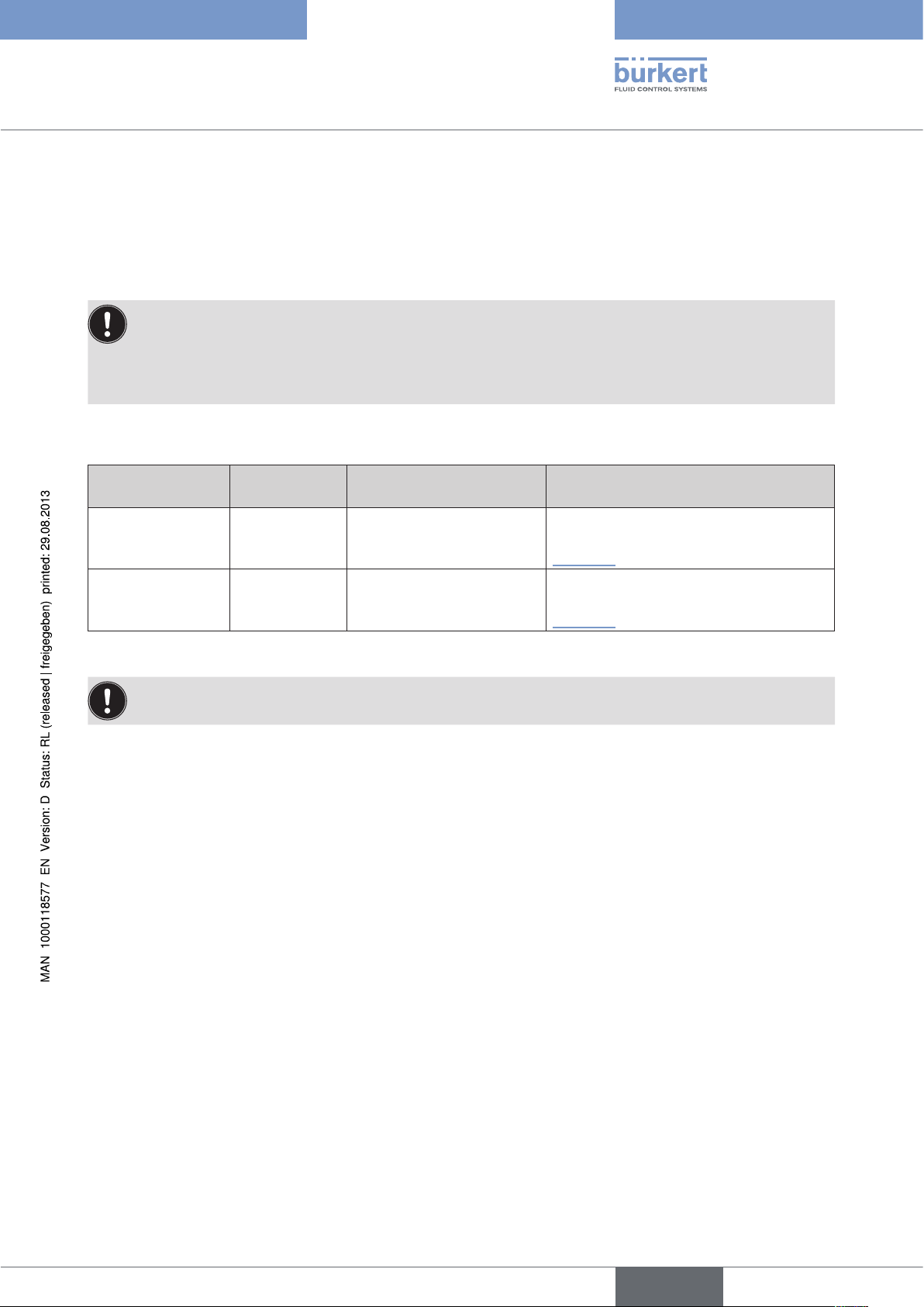
12.4.3. Connection and start-up via a 4 – 20 mA path sensor (for Type 8793 remote model only)
When a 4 – 20 mA path sensor is connected, the process controller Type 8793 can be used as a positioner
(position controller) only, as the process actual value input is used as input for the path sensor.
In principle, any path sensor with a 4 – 20 mA output can be connected which has an adequate resolution of the
path signal.
Good control properties are obtained if the resolution of the path sensor allows at least 1000 measuring steps
over the path to be measured.
Example: Path sensor with 150 mm measurement range
Of which used measurement range (= stroke) 100 mm
Required minimum resolution of the sensor:
100 mm
1000 Steps
= 0.1 mm
WARNING!
Risk of injury from improper start-up!
• Start-up may be carried out by authorised technicians only and with the appropriate tools!
Risk of injury from unintentional activation of the system and an uncontrolled restart!
• Secure system from unintentional activation.
• Following assembly, ensure a controlled restart.
Connect 4 – 20 mA path sensor to the terminals 1 - 4 of the process controller Type 8793 remote model.
(see chapter “Table 21: Terminal assignments of the process actual value input”, page 60 /
Internal supply of the path sensor by Type 8793:
→ Connection according to input type “4 ... 20 mA - internally supplied”
Separate supply of the path sensor:
→ Connection according to input type “4 ... 20 mA - externally supplied”.
→ Attach remote sensor on the actuator.
The correct procedure is described in the instructions for the path sensor.
→ Connect compressed air to the Type 8793.
48
→ Connect Type 8793 pneumatically to the actuator
→ Switch on Type 8793 operating voltage.
→ To obtain the best possible control precision, adjust the path sensor so that path to be measured corresponds
to the signal range 4 – 20 mA (only if the path sensor includes this function).
→ In the ADD.FUNCTION menu activate the POS.SENSOR function. Then select POS.SENSOR in the main
menu and set ANALOG.
(see chapter “26.2.19. POS.SENSOR – Setting interface remote path sensor”, page 142.
→ Run the X.TUNE function.
english
Page 49

Type 8792, 8793
Installation
13. FLUID CONNECTION
13.1. Safety instructions
DANGER!
Risk of injury from high pressure in the equipment!
• Before loosening the pneumatic lines and valves, turn off the pressure and vent the pneumatic lines.
WARNING!
Risk of injury from improper installation!
• Installation may be carried out by authorized technicians only and with the appropriate tools!
Risk of injury from unintentional activation of the system and an uncontrolled restart!
• Secure system from unintentional activation.
• Following installation, ensure a controlled restart.
Working connection 2
(connection: A2)
Supply pressure connection 1.4 – 7 bar
(connection: P)
Working connection 1 <
(connection: A1)
Deaeration connection
Figure 23: Fluid installation / Location of the connections
49
english
Page 50

Type 8792, 8793
Installation
Procedure:
→ Apply supply pressure (1.4 – 7 bar) to the supply pressure connection P.
For single-acting actuators (control function A and B):
→ Connect one working connection (A1 or A2, depending on required safety position) to the chamber of the
single-acting actuator.
Safety positions see chapter “11.8. Safety end positions after failure of the electrical or pneumatic auxiliary
power”.
→ Seal a working connection which is not required with a plug.
For double-acting actuators (control function I):
→ Connect working connections A1 and A2 to the respective chambers of the double-acting actuator
see chapter “11.8. Safety end positions after failure of the electrical or pneumatic auxiliary power”.
Important information for perfect control behaviour!
This ensures that the control behaviour is not extremely negatively affected in the upper stroke range on
account of too little pressure difference.
• keep the applied supply pressure at least 0.5 – 1 bar above the pressure which is required to move the
pneumatic actuator to its end position.
If fluctuations are greater, the control parameters measured with the X.TUNE function are not optimum.
• during operation keep the fluctuations of the supply pressure as low as possible (max. ±10%).
50
english
Page 51

Type 8792, 8793
Installation
14. ELECTRICAL CONNECTION - CIRCULAR PLUG-IN CONNECTOR VERSION (MULTI-POLE VERSION)
DANGER!
Risk of injury due to electrical shock!
• Before reaching into the device or the equipment, switch off the operating voltage and secure to prevent
reactivation!
• Observe applicable accident prevention and safety regulations for electrical equipment!
Risk of explosion if used in Ex area!
To avoid the risk of explosion, connect the Ex device to the power supply as described below:
• Secure cable connections, which use circular connectors, with suitable locking clips.
(For example: EXCLIP, FA. Phoenix Contact,
Type SAC-M12-EXCLIP-M, Art. no. 1558988 or
Type SAC-M12-EXCLIP-F, Art. no. 1558991.
• Use only cable and line entry points which have been approved for the respective application area. Screw
cable and line entry points into place according to the associated installation instructions.
• Install pre-assembled cable glands according to the installation instructions supplied by the cable gland
manufacturer.
Before start-up in the Ex area, check whether the cable gland was installed as described in these installation
instructions.
• Close all unnecessary cable glands with lock screws approved for the explosions area.
WARNING!
Risk of injury from improper installation!
• Installation may be carried out by authorized technicians only and with the appropriate tools!
Risk of injury from unintentional activation of the system and an uncontrolled restart!
• Secure system from unintentional activation.
• Following installation, ensure a controlled restart.
Using the 4 – 20 mA set-point value input
If several devices of Type 8792/8793 are connected in series and the power supply to a device in this
series connection fails, the input of the failed device becomes highly resistive.
As a result, the 4 – 20 mA standard signal fails.
In this case please contact Bürkert Service directly.
If PROFIBUS DP or DeviceNet:
The designation of the circular plug-in connectors and sockets and the contacts can be found in the
respective chapters.
english
51
Page 52

Type 8792, 8793
Installation
14.1. Type 8792 - designation of the circular plug-in connectors
Operating voltage
and diverse signals
12
8
3
4
5
X1 - M12, 8-pole circular connector
Figure 24: Type 8792; designation of the circular plug-in connectors and contacts
7
6
Functional earth FE
Binary outputs
optional
1
X4 - M8, 4-pole socket
14.2. Connection of the positioner Type 8792
→ Connect pins according to the model (options) of the positioner.
14.2.1. X1 - M12, 8-pole circular connector
Pin Wire colour* Configuration On the device side External circuit / Signal level
3
42
Input signals of the control centre (e.g. PLC)
1 white Set-point value
+ (0/4 – 20 mA or 0 – 5/10 V
2 brown Set-point value GND
5 grey Binary input
6 pink Binary input GND
Output signals to the control centre (e.g. PLC) - (only used for analog output option)
8 red Analogue feedback +
7 blue Analogue feedback GND
Operating voltage
3 green GND
4 yellow +24 V
* The indicated wire colours refer to the connection cable, part no. 919061, available as an accessory.
1
2
5
6
8
7
3
4
+ (0/4 – 20 mA or 0 – 5 / 10 V)
completely galvanically isolated
GND set-point value
+
GND (identical with the GND
operating voltage)
+ (0/4 – 20 mA or 0 – 5 / 10 V)
completely galvanically isolated
GND Analogue feedback
24 V DC ± 10%
max. residual ripple 10%
0 – 5 V (log. 0)
10 – 30 V (log. 1)
52
Table 13: Pin assignment; X1 - M12, 8-pole circular connector
english
Page 53

Type 8792, 8793
Installation
14.2.2. X4 - M8, 4-pole socket (for binary outputs option only) Output signals to the control centre (e.g. PLC)
Pin Configuration On the device side External circuit / Signal level
1 Binary output 1
2 Binary output 2
3 Binary output GND
Table 14: Pin assignment; X4 - M8, 4-pole socket - output signals to the control centre
When the operating voltage is applied, the positioner is operating.
1
2
3
0 – 24 V
0 – 24 V
GND (identical with the GND operating
voltage)
→ Now make the required basic settings and actuate the automatic adjustment of the positioner. The procedure is
described in chapter “21. Start-up sequence”.
english
53
Page 54

Type 8792, 8793
Installation
14.3. Type 8793 - designation of the circular plug-in connectors and contacts
Operating voltage
and diverse signals
3
4
5
X1 - M12, 8-pole
circular connector
(Description see
“Table 13”)
Process actual value
12
8
7
3
6
24
X5 - M8, 4-pole
circular connector
(Description see
“Table 15”
Binary outputs
1
1
X4 - M8, 4-pole socket
(Description see
“Table 14”)
3
42
Functional earth FE
54
Figure 25: Type 8793; designation of the circular plug-in connectors and contacts
Location of the DIP switch:
Symbols for
switch position
Switch on right
Switch on left
Figure 26: Location of the DIP switch; symbols for switch position
Location of the
DIP switch
english
Page 55

Type 8792, 8793
Installation
14.4. Connecting the process controller Type 8793
→ First connect the process controller as described in chapter “14.2. Connection of the positioner Type 8792”.
14.4.1. X5 - M8, 4-pole circular connector, plug assignments of the process actual value input
Input type* Pin
4 – 20 mAinternally
supplied
4 – 20 mAexternally
supplied
Frequencyinternally
supplied
Frequencyexternally
supplied
1 brown +24 V transmitter supply
2 white Output from transmitter
3 blue GND (identical with GND
4 black Bridge to GND (Pin 3)
1 brown not used
2 white Process actual + 2
3 blue not used
4 black Process actual – 4
1 brown +24 V sensor supply
2 white Clock input + 2 Clock +
3 blue Clock input – (GND) 3 Clock – / GND
4 black not used
1 brown not used
2 white Clock input + 2
3 blue Clock input – 3 Clock –
4 black not used
Wire
colour**
Configuration
operating voltage)
DIP
switches
Switch
on left
Switch
on right
Switch
on left
Switch
on right
On the
device side
1
2
3
4
1
External circuit
Transmitter
GND
4 - 20 mA
GND 4 - 20 mA
+24 V
(identical with GND
operating voltage)
Clock +
Pt 100
(see information
below)
* Can be adjusted via software (see chapter “21. Start-up sequence”).
** The indicated colors refer to the connection cable available as an accessory (918718).
Table 15: Pin assignment; X5 - M8, 4-pole circular connector - process actual value input
Connect the Pt 100 sensor via 3 cables for cable compensation reasons. It is essential to bridge Pin 3
and Pin 4 on the sensor.
When the operating voltage is applied, the process controller is operating.
1 brown not used
2 white Process actual 1 (power supply)
3 blue Process actual 3 (GND)
4 black Process actual 2 (compensation)
Switch
on right
2
Pt 100
3
4
→ Now make the required basic settings and actuate the automatic adjustment of the process controller. The
procedure is described in chapter “21. Start-up sequence”.
english
55
Page 56

Type 8792, 8793
Installation
15. ELECTRICAL CONNECTION - TERMINAL VERSION FOR CABLE GLAND
DANGER!
Risk of injury due to electrical shock!
• Before reaching into the device or the equipment, switch off the operating voltage and secure to prevent
reactivation!
• Observe applicable accident prevention and safety regulations for electrical equipment!
Risk of explosion if used in Ex area!
To avoid the risk of explosion, connect the Ex device to the power supply as described below:
• Use only cable and line entry points which have been approved for the respective application area. Screw
cable and line entry points into place according to the associated installation instructions.
• Install pre-assembled cable glands according to the installation instructions supplied by the cable gland
manufacturer.
Before start-up in the Ex area, check whether the cable gland was installed as described in these installation
instructions.
• Close all unnecessary cable glands with lock screws approved for the explosions area.
WARNING!
Risk of injury from improper installation!
• Installation may be carried out by authorized technicians only and with the appropriate tools!
Risk of injury from unintentional activation of the system and an uncontrolled restart!
• Secure system from unintentional activation.
• Following installation, ensure a controlled restart.
Using the 4 – 20 mA set-point value input
If several devices of Type 8792/8793 are connected in series and the power supply to a device in this
series connection fails, the input of the failed device becomes highly resistive.
As a result, the 4 – 20 mA standard signal fails.
In this case please contact Bürkert Service directly.
56
english
Page 57

Type 8792, 8793
Installation
15.1. Connection board of the Type 8792/8793 with screw-type terminals
1
2
3
4
+24 V
GND
83 +
85 +
31 +
32 –
11 +
12 –
81 +
Figure 27: Designation of the screw-type terminals
Procedure:
Optional:
S +
S –
A
B
→ Unscrew the 4 screws on the housing cover and remove the cover.
The screw-type terminals are now accessible.
→ Connect Type 8792/8793.
The procedure is described in the following chapters.
for Type 8792: chapter “15.2. Terminal assignment for cable gland - positioner Type 8792”
for Type 8793: chapter “15.3. Terminal assignment for cable gland - process controller Type 8793”
15.2. Terminal assignment for cable gland - positioner Type 8792
15.2.1. Input signals from the control centre (e.g. PLC)
Terminal Configuration On the device side External circuit / Signal level
11 + Set-point value +
12 – Set-point value GND
81 +
Table 16: Terminal assignment; input signals of the control centre
Binary input +
11 +
12 –
81 +
+ (0/4 – 20 mA or 0 – 5 / 10 V)
completely galvanically isolated
GND set-point value
+
specific to operating voltage GND
(terminal GND)
0 – 5 V (log. 0)
10 – 30 V (log. 1)
57
english
Page 58
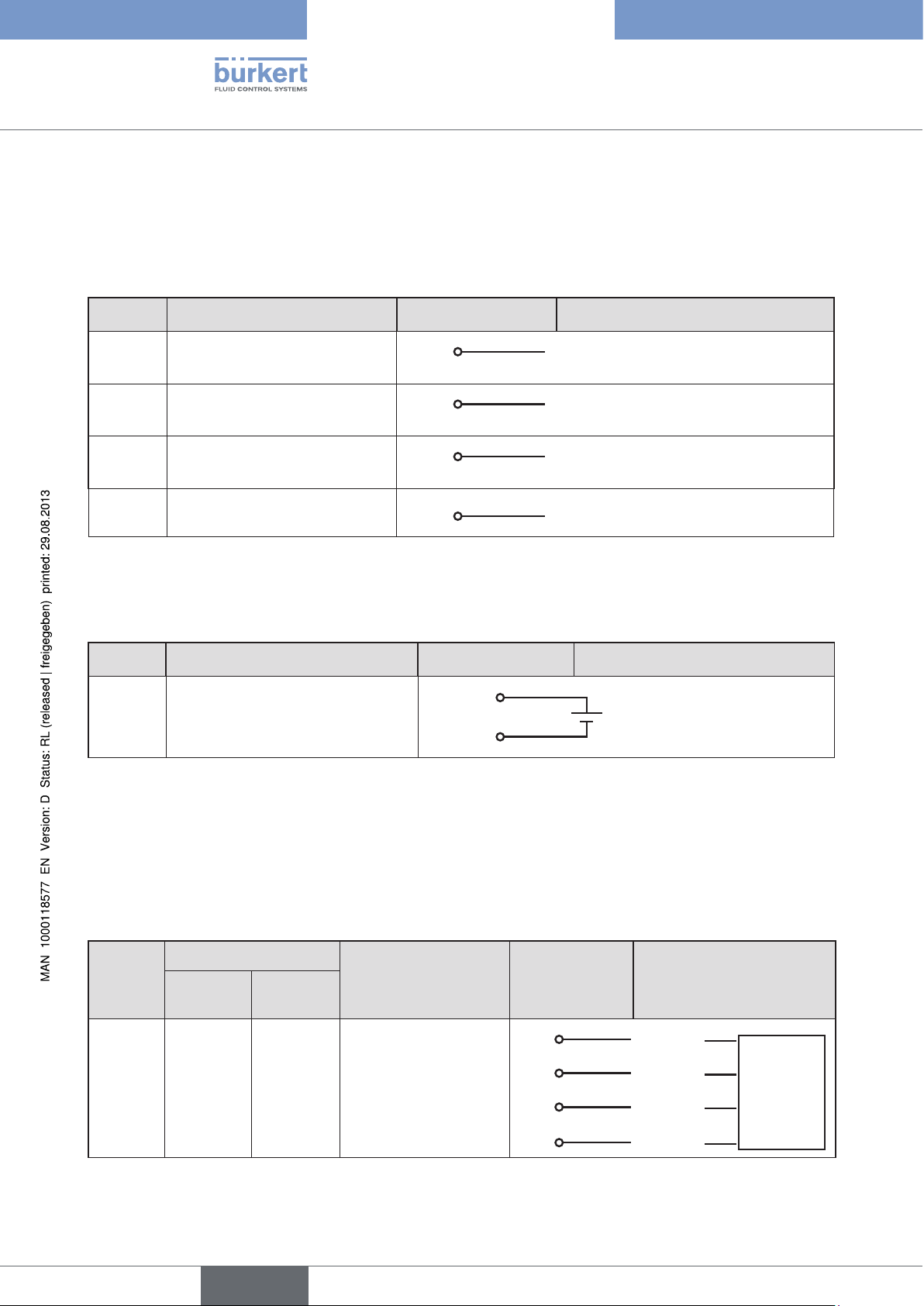
Type 8792, 8793
Installation
15.2.2. Output signals to the control centre (e.g. PLC) (required for analogue output and/or binary output option only)
→ Connect terminals according to the model (options) of the positioner.
Terminal Configuration On the device side External circuit / Signal level
83 + Binary output 1
85 + Binary output 2
31 + Analogue feedback +
32 – Analogue feedback GND
Table 17: Terminal assignment; output signals to the control centre
83 +
85 +
31 +
32 –
24 V / 0 V, NC / NO specific to
operating voltage GND (terminal GND)
24 V / 0 V, NC / NO specific to
operating voltage GND (terminal GND)
+ (0/4 – 20 mA or 0 – 5 / 10 V)
completely galvanically isolated
GND Analogue feedback
15.2.3. Operating voltage
Terminal Configuration On the device side External circuit / Signal level
+24 V Operating voltage +
GND Operating voltage GND
Table 18: Terminal configuration; operating voltage
+24 V
GND
24 V DC ± 10%
max. residual ripple 10%
58
15.2.4. Terminal assignment for external position sensor (for remote model only)
Connection of the digital, contact-free position sensor Type 8798:
Wire colour
Terminal
S + brown brown Supply sensor +
S - white black Supply sensor –
A green red Serial interface, A-line
B yellow orange Serial interface, B-line
Table 19: Terminal assignment; digital, contact-free position sensor Type 8798
Cable type 1Cable type
2
english
Configuration
On the device
side
S +
S –
A
B
External circuit / Signal
level
+
–
A-line
B-line
Remote
Sensor
Type 8798
digital
Page 59

Type 8792, 8793
Installation
Connection of a potentiometric position sensor:
Terminal Configuration On the device side External circuit
Potentiometer 1
Center tap 2
Potentiometer 3
Table 20: Terminal assignment; potentiometric position sensor
When the operating voltage is applied, the positioner is operating.
1
2
3
Center tap
Potentiometer
→ Now make the required basic settings and actuate the automatic adjustment of the positioner. The procedure is
described in chapter “21. Start-up sequence” .
15.3. Terminal assignment for cable gland - process controller Type 8793
→ First connect the process controller as described in chapter “15.2. Terminal assignment for cable gland -
positioner Type 8792”
15.3.1. Terminal assignments of the process actual value input
Input type* Terminal Configuration On the device side External circuit
4 – 20 mA
- internally
supplied
4 – 20 mA
- externally
supplied
Frequency
- internally
supplied
1 +24 V transmitter input
2 Output from transmitter
3 Bridge to GND (Terminal GND
actual value
GND GND from operating voltage
actual value
actual value
GND GND from operating voltage GND Clock – (GND)
from operating voltage)
4 not used
1 not used
2 Process actual + 2
3 Process actual – 3 GND 4 – 20 mA
4 not used
1 +24 V sensor supply 1 +24 V
2 Clock input + 2 Clock +
3 not used
4 Clock input – 4
GND
1
2
3
Transmitter
GND
+ (4 – 20 mA)
59
english
Page 60

Type 8792, 8793
Installation
Input type* Terminal Configuration On the device side External circuit
Frequency
- externally
supplied
1 not used
2 Clock input + 2
Clock +
3 not used
actual value
4 Clock input – 4
Pt 100
(see information
below)
* Can be adjusted via software (see chapter“21. Start-up sequence”).
Table 21: Terminal assignments of the process actual value input
1 not used
2 Process actual 1 (Power supply)
3 Process actual 3 (GND)
actual value
4 Process actual 2 (Compensation)
2
3
4
Clock –
Pt 100
Connect the Pt 100 sensor via 3 cables for cable compensation reasons.
It is essential to bridge Pin 3 and Pin 4 on the sensor.
When the operating voltage is applied, the process controller is operating.
→ Now make the required basic settings and actuate the automatic adjustment of the process controller. The
procedure is described in chapter “21. Start-up sequence”.
60
english
Page 61

Type 8792, 8793
Operation
conTenTs
16. OPERATING LEVELS .......................................................................................................................................................................62
Switching between the operating levels ................................................................................................................62
16.1.
OPERATING AND DISPLAY ELEMENTS ...............................................................................................................................63
17.
Description of the operating and display elements .........................................................................................63
17.1.
17.1.1. Description of the symbols which are displayed on the process level ................................64
Function of the keys ..........................................................................................................................................................65
17.2.
17.2.1. Entering and changing numerical values ....................................................................................66
Adjusting the display ........................................................................................................................................................67
17.3.
17.3.1. Possible displays of the process level ........................................................................................ 67
Date and time ........................................................................................................................................................................69
17.4.
17.4.1. Setting date and time: ....................................................................................................................70
OPERATING STATES ......................................................................................................................................................................71
18.
Changing the operating state .......................................................................................................................................71
18.1.
ACTIVATING AND DEACTIVATING AUXILIARY FUNCTIONS ....................................................................................72
19.
19.1.1. Activating auxiliary functions .......................................................................................................... 72
19.1.2. Deactivating auxiliary functions ..................................................................................................... 73
MANUALLY OPENING AND CLOSING THE VALVE .........................................................................................................74
20.
English
61
Page 62

Type 8792, 8793
Operation
16. OPERATING LEVELS
There is the process level and the setting level for the operation and setting of type 8792/8793.
Process level:
The running process is displayed and operated on the process level.
Operating state: AUTOMATIC – Displaying the process data
MANUAL – Manually opening and closing the valve
Setting level:
The basic settings for the process are made on the setting level.
– Inputting the operating parameters
– Activating auxiliary functions
If the device is in the AUTOMATIC operating state when changing to the setting level, the process continues
running during the setting.
16.1. Switching between the operating levels
Change to the setting level
Return to the process level
The set MANUAL or AUTOMATIC operating state is retained even when the operating level is changed.
Change to the setting level
MENU
EXIT
Return to the process level
Press for 3 seconds
Press briefly
62
Left selection key
Press for 3 seconds
Figure 28: Changing operating level
English
Progress bar
closes
Left selection key
Press
Page 63

Type 8792, 8793
Operation
17. OPERATING AND DISPLAY ELEMENTS
The following chapter describes the operating and display elements of Type 8792/8793.
17.1. Description of the operating and display elements
The device is operated by four keys and a 128x64 dot matrix graphics display.
The display is adjusted to the set functions and operating levels.
In principle, a distinction can be made between the display view for the process level and the setting level.
When the operating voltage has been applied, the process level is displayed.
Display elements of the process level:
Save symbol
Symbol for position control
Symbol for process control
Symbol for the AUTOMATIC operating state
Other symbols are displayed according to the activated
functions. See "Table 22"
Abbreviated designation for the displayed
process value
Unit of the displayed process value
Process value *
Designation for the function of the keys
Operating elements:
Right selection key
Arrow key , down arrow
Arrow key
Left selection key
, up arrow
* The process values which can be displayed in the AUTOMATIC operating state depend on type.
A detailed description can be found in Chapter "17.3.1. Possible displays of the process level"
Figure 29: Display and operating elements of the process level
English
63
Page 64

Display elements of
the setting level:
Menu designation
Submenu
Designation for the
function of the keys
Type 8792, 8793
Operation
Operating elements:
Right selection key
Arrow key , down arrow
Arrow key
, up arrow
Left selection key
Figure 30: Display and operating elements of the setting level
17.1.1. Description of the symbols which are displayed on the process level
The symbols which are displayed depend on
• type,
• operation as position or process controller,
• AUTOMATIC or MANUAL operating state and
• the activated functions.
Operation Symbol Description
Types 8792/8793
Operation as
position controller
AUTOMATIC operating state
Diagnosis active (optional; only available if the device has the additional
software for the diagnosis)
X.CONTROL / Position controller active (symbol is indicated for Type 8793 only)
64
Save EEPROM (is indicated during the save process)
CUTOFF active
SAFEPOS active
Interface I/O Burst
Interface I/O RS232 HART
SECURITY active
Other symbols for
Type 8793
Operation as
process controller
Table 22: Symbols of the process level.
P.CONTROL / Process controller active
Bus active
SIMULATION active
English
Page 65

Type 8792, 8793
Operation
17.2. Function of the keys
The functions of the 4 operating keys differ depending on the operating state (AUTOMATIC or MANUAL) and
operating level (process level or setting level).
The key function which is active is displayed in the gray text field which is above the key.
The description of the operating levels and operating states can be found in
Chapter "16. Operating levels" and "18. Operating states".
Key function on the process level:
Key Key function Description of the function Operating state
Arrow key
Arrow key
Left
selection key
OPN
CLS
MENU
(OPEN)
(CLOSE)
Manual opening of the actuator.
Change the displayed value
(e.g. POS-CMD-TEMP-...).
Manual closing of the actuator.
Change the displayed value
(e.g. POS-CMD-TEMP-...).
Change to the setting level.
Note: Press key for approx. 3 s.
MANUAL
AUTOMATIC
MANUAL
AUTOMATIC
AUTOMATIC or
MANUAL
Right
AUTO
Return to AUTOMATIC operating state.
selection key
MANUAL
Change to MANUAL operating state.
Key function on the setting level:
Key Key function Description of the function
Arrow key Scroll up in the menus.
Arrow key
Left
selection key
Right
selection key
+
–
< –
EXIT
ESC
STOP
ENTER
SELEC
OK
INPUT
EXIT
RUN
(BACK)
(BACK)
Increase numerical values.
Scroll down in the menus.
Decrease numerical values.
Change by one digit to the left; when entering numerical values.
Return to the process level.
Gradually return from a submenu option.
Leave a menu.
Stop a sequence.
Select, activate or deactivate a menu option.
Gradually return from a submenu option.
Start a sequence.
MANUAL
AUTOMATIC
STOP
Table 23: Function of the keys
Stop a sequence.
65
English
Page 66

17.2.1. Entering and changing numerical values
Changing numerical values with fixed decimal places:
Type 8792, 8793
Operation
Key
Arrow key
Key
function
Description of the function Example
Change to the next decimal place (from right to left).
After reaching the last decimal place, the display
switches back to the first decimal place.
Arrow key
Increase value.
When the largest possible value has been reached,
0 is displayed again.
Left
selection key
Right
ESC
or
EXIT
OK
Return without change.
Accept the set value.
selection key
Table 24: Change numerical values with fixed decimal places.
Enter numerical values with variable decimal places:
Key
Arrow key
Arrow key
Left
selection key
Key
function
ESC
or
EXIT
Description of the function Example
Increase value.
Reduce value.
Return without change.
Enter date and time.
Enter PWM signal
66
Right
OK
Accept the set value.
selection key
Table 25: Enter numerical values with variable decimal places.
English
Page 67

Type 8792, 8793
Operation
17.3. Adjusting the display
The display can be individually adjusted for the operation and monitoring of the process.
• To do this, menu options can be activated for displaying the process level. POS and CMD are activated in the
as-delivered state.
• The menu options which can be displayed depend on the type.
How you can adjust the display for Type 8792 individually to the process to be controlled is described in
Chapter
17.3.1. Possible displays of the process level
"26.2.18. EXTRAS – Setting the display", page 140 ".
Possible displays in AUTOMATIC operating state
POS
MENU
CMD/POS
0.0
CMD MANU
Actual position of the valve actuator
(0 ... 100 %)
• Set-point position of the valve actuator or
CMD
0.0
MENU POS TEMP MANU
TEMP
C
MENU CMD
0.0
CMD/POS
• Set-point position of the valve actuator after rescaling by possibly
activated split range function or correction characteristic
(0 ... 100 %)
Internal temperature in the housing of the device
( °C)
Process actual value
PV
m3/min
MENU TEMP SP MANU
0.0
Only for type 8793
SP
m3/min
MENU PV PV
MENU HOLD
SP / PV (t)
0.0
(t)
INPUT
Process set-point value
Right selection key
The key function depends on the set-point value default
(menu: P.CONTROL→ P.SETUP → SP-INPUT → internal/external).
INPUT
Set-point value default = internal
MANU
Set-point value default = external
Only for type 8793
Graphical display of SP and PV with time axis
Only for type 8793
:
English
67
Page 68

Type 8792, 8793
Operation
Possible displays in AUTOMATIC operating state
Graphical display of POS and CMD with time axis
CMD / POS (t)
MENU HOLD
CLOCK
12:00
00
Time, weekday and date
Thu. 01 . 09 . 11
INPUT X.TUNE
MENU
INPUT
mA
CMD/POS
MENU
X.TUNE
CLOCK
MENU
4.0
CLOCK
CMD/POS
INPUT
Input signal for set-point position
(0 ... 5/10 V or 0/4 ... 20 mA)
Only for operation as position controller
Automatic adjustment of the position controller
RUN
P.TUNE
Automatic optimization of the process controller parameters
Only for type 8793
X.TUNE
MENU
P.LIN RUN
Automatic linearization of the process characteristics
P.LIN
Only for type 8793
CMD/POS
P.TUNE
MENU
CMD
POS
MENU P.LIN SP/PV MANU
SP
m3/min
PV
m3/min
CMD/POS
MENU
Table 26: Displays of the process level in AUTOMATIC operating state
RUN
0.0
0.0
0.0
0.0
POS MANU
Simultaneous display of the set-point position and the actual position
of the valve actuator
(0 ... 100 %)
Simultaneous display of the set-point position and the actual position
of the valve actuator
(0 ... 100 %)
Only for type 8793
68
English
Page 69

Type 8792, 8793
Operation
17.4. Date and time
Date and time are set on the process level in the CLOCK menu.
To ensure that the input menu for CLOCK can be selected on the process level, the following functions must be
activated in 2 stages:
1. The EXTRAS auxiliary function in the ADD.FUNCTION menu
2. The CLOCK function in the EXTRAS auxiliary function, DISP.ITEMS submenu.
Activating EXTRAS and CLOCK:
Key Action Description
MENU
Press for approx. 3 s
/ Select ADD.FUNCTION
ENTER
Press
/ Select EXTRAS
ENTER
EXIT
Press
Press
/ Select EXTRAS
ENTER
Press
/ Select DISP. ITEMS
ENTER
Press
/ Select CLOCK
SELEC
Press
Switching from process level setting level.
The possible auxiliary functions are displayed.
Activate the EXTRAS auxiliary function by marking with a cross
and transfer into the main menu (MAIN).
Return to the main menu (MAIN).
The submenus of EXTRAS are displayed.
The possible menu options are displayed.
The activated CLOCK function is now marked by a cross .
EXIT
EXIT
EXIT
Table 27: EXTRAS; Activating the CLOCK function
Press
Press
Press
Return to the EXTRAS menu.
Return to the main menu (MAIN).
Switching from setting level process level.
Date and time must be reset whenever the device is restarted.
After a restart the device therefore switches immediately and automatically to the corresponding input
menu.
69
English
Page 70

17.4.1. Setting date and time:
→ On the process level select the display for CLOCK using the arrow keys.
Type 8792, 8793
Operation
→ Press
INPUT
to open the input screen for the setting.
→ Set date and time as described in the following table.
Key
Arrow key
Arrow key
Left
selection key
Right
selection key
Key
function
ESC
OK
Description of the function Input screen
Switch to the next time unit (from right to left).
When the last time unit for the date has been
reached, the display switches to the time units for
the time.
If the last unit is at top left (hours), the display
switches back to the first unit at bottom right (year).
Increase value.
When the largest possible value has been reached,
0 is displayed again.
Return without change.
Accept the set value.
Switching the display.
CLOCK
00
12:00
Thu. 01 . 09 . 11
<–
MENU
+
INPUT
Table 28: Setting date and time
70
English
Page 71

Type 8792, 8793
Operation
18. OPERATING STATES
Type 8792/8793 has 2 operating states: AUTOMATIC and MANUAL.
When the operating voltage is switched on, the device is in the AUTOMATIC operating state.
AUTOMATIC In the AUTOMATIC operating state normal
POS
0.0
MENU CMD POS MANU
MANUAL In the MANUAL operating state the valve can be manually
POS
0.0
MENU OPN CLS AUTO
controlled operation is implemented.
(The symbol for AUTOMATIC
(A bar runs along the upper edge of the display).
opened or closed via the arrow keys (key function
OPN
(The symbol for AUTOMATIC
(No bar running along the upper edge of the display).
and
CLS
).
is shown on the display.
is hidden.
The MANUAL operating state (key function
POS, CMD, PV, CMD/POS, SP/PV.
For SP only for external process set-point value.
MANU
is for the following process value displays only:
)
18.1. Changing the operating state
MANUAL or AUTOMATIC operating state is switched on the process level.
When switching to the setting level, the operating state is retained.
Change to MANUAL operating state
Return to AUTOMATIC operating
state
MANU
AUTO
press Only available for process value display:
POS, CMD, PV, SP
press
English
71
Page 72

Type 8792, 8793
Operation
19. ACTIVATING AND DEACTIVATING AUXILIARY FUNCTIONS
Auxiliary functions can be activated for demanding control tasks.
The auxiliary function is activated via the ADD.FUNCTION basic function and transferred to the main
menu (MAIN).
The auxiliary functions can then be selected and set in the extended main menu (MAIN).
19.1.1. Activating auxiliary functions
Procedure:
Key Action Description
MENU
Press for approx. 3 s
/ Select ADD.FUNCTION
ENTER
Press
/ Select required auxiliary
function
ENTER
EXIT
Press
Press
Switching from process level setting level.
The possible auxiliary functions are displayed.
The selected auxiliary function is now marked by a cross .
Acknowledgment and simultaneous return to the main menu (MAIN).
The marked function is now activated and incorporated into the
main menu.
The parameters can then be set as follows.
/ Select the auxiliary function In the main menu (MAIN) select the auxiliary function.
ENTER
Press
Opening the submenu to input the parameters.
The setting of the submenu is described in the respective chapter of
the auxiliary function.
Return from the submenu and switch to the process level
EXIT
*
Press
ESC
*
EXIT
* The designation of the key depends on the selected auxiliary function.
Table 29: Activating auxiliary functions
Press
Return to a higher level or to the main menu (MAIN).
Switching from setting level process level.
72
English
Page 73

Type 8792, 8793
Operation
19.1.1.1. Principle: Activating auxiliary functions with simultaneous
incorporation into the main menu
Functions in the main menu
Setting level
MAIN
INPUT
X.TUNE
ADD.FUNCTION
EXIT ENTER
7
(Standard)
INPUT
X.TUNE
ADD.FUNCTION
ENTER
Activating the auxiliary function
CHARACT
EXTRAS
EXIT
DIAGNOSE
Extended main menu
MAIN
X.TUNE
ADD.FUNCTION
CARACT
X.CONTROL
EXIT ENTER
15
INPUT
X.TUNE
ADD.FUNCTION
CHARACT
EXTRAS
Figure 31: Principle: Activating auxiliary functions with simultaneous incorporation into the main menu (MAIN)
19.1.2. Deactivating auxiliary functions
Procedure:
Key Action Description
MENU
Press for approx. 3 s
/ Select ADD.FUNCTION
ENTER
Press
/ Select the auxiliary function
ENTER
EXIT
Table 30: Deactivating auxiliary functions
Press
Press
Switching from process level setting level.
The possible auxiliary functions are displayed.
Remove function mark (no cross ).
Acknowledgment and simultaneous return to the main menu (MAIN).
The marked function is now deactivated and removed from the
main menu.
Deactivation removes the auxiliary function from the main menu (MAIN). This will cause the previous settings, created under this function, to be rendered invalid.
English
73
Page 74
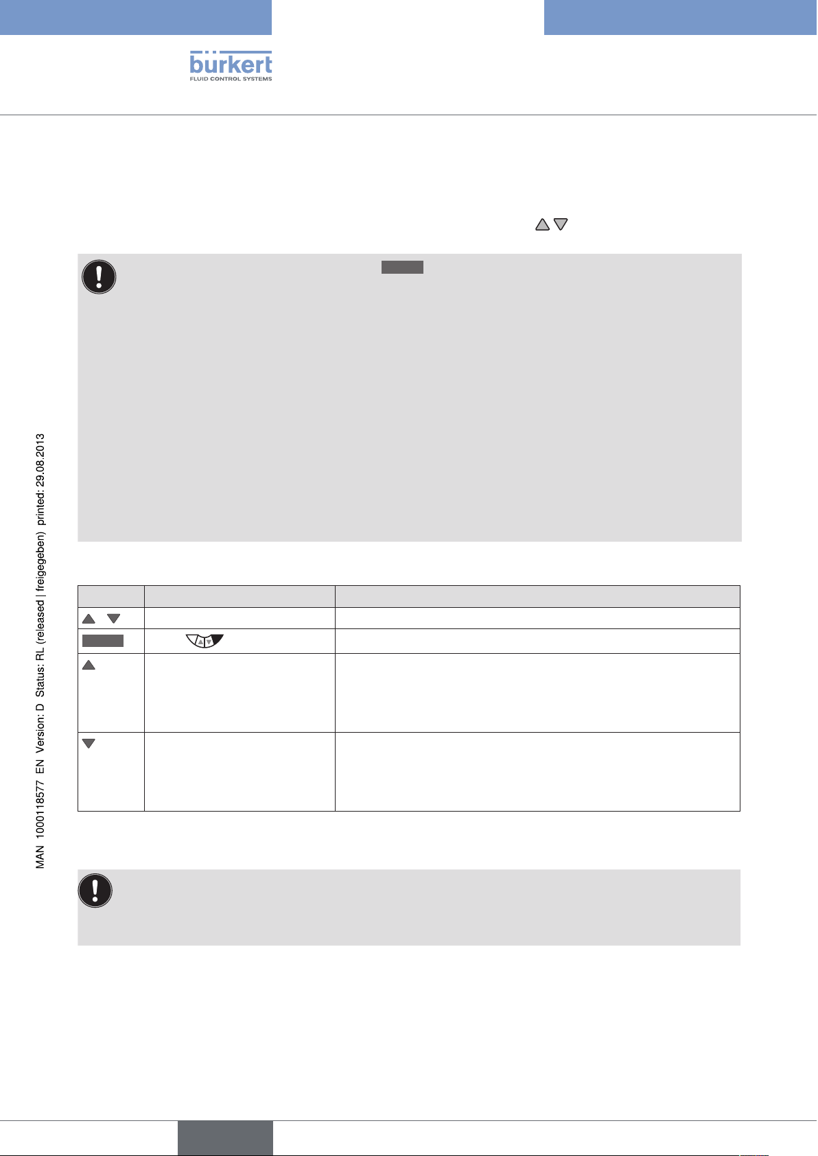
Type 8792, 8793
Operation
20. MANUALLY OPENING AND CLOSING THE VALVE
In the MANUAL operating state, the valve can be opened and closed manually using the arrow keys.
The MANUAL operating state (key function
• POS, actual position of the valve actuator.
• CMD, set-point position of the valve actuator.
When switching to MANUAL operating state, POS is displayed.
• PV, process actual value.
• SP, process set-point value.
When switching to MANUAL operating state, PV is displayed. The switch is possible only for external
set-point value default (menu: P.CONTROL→ P.SETUP → SP-INPUT → external).
• CMD/POS, set-point position of the valve actuator.
When switching to MANUAL operating state, POS is displayed.
• SP/PV, process set-point value.
When switching to MANUAL operating state, PV is displayed. The switch is possible only for external
set-point value default (menu: P.CONTROL→ P.SETUP → SP-INPUT → external).
Manually opening and closing valve:
Key Action Description
/
MANU
Select POS, CMD, PV or SP
Press
press Aerate the actuator
Change to MANUAL operating state
MANU
is for the following process value displays:
)
74
Control function A (SFA): Valve opens
Control function B (SFB): Valve closes
Control function I (SFI): Connection 2.1 aerated
press Bleed the actuator
Control function A (SFA): Valve closes
Control function B (SFB): Valve opens
Control function I (SFI): Connection 2.2 aerated
Table 31: Manually opening and closing the valve
SFA: Actuator spring force closing
SFB: Actuator spring force opening
SFI: Actuator double-acting
English
Page 75

Type 8792, 8793
Start-Up
conTenTs
21. START-UP SEQUENCE ..................................................................................................................................................................76
SAFETY INSTRUCTIONS ..............................................................................................................................................................76
22.
BASIC SETTING OF THE DEVICE ...........................................................................................................................................77
23.
INPUT - Setting the input signal ............................................................................................................................78
23.1.
X.TUNE – Automatic adjustment of the position controller ..................................................................79
23.2.
23.2.1. X.TUNE.CONFIG – Manual configuration of X.TUNE ............................................81
ACTIVATION OF THE PROCESS CONTROLLER ..............................................................................................................82
24.
BASIC SETTING OF THE PROCESS CONTROLLER .....................................................................................................83
25.
25.1. P.CONTROL – Setting up and parameterization of the process controller .................................83
25.2. SETUP
25.2.1. PV-INPUT – Specifying signal type for the process actual value .................................. 85
25.2.2. PV-SCALE – Scaling of the process actual value ............................................................86
25.2.3. SP-INPUT – Type of the set-point value default (internal or external) ..........................90
25.2.4. SP-SCALE – Scaling of the process set-point value
25.2.5. P.CO-INIT – Smooth switchover MANUAL-AUTOMATIC ...............................................92
PID.PARAMETER – Parameterizing the process controller .............................................................93
25.3.
25.3.1. Procedure for inputting the parameters ......................................................................................93
25.3.2. DBND – Insensitivity range (dead band)...............................................................................94
25.3.3. KP – Amplification factor of the process controller ..............................................................94
25.3.4. TN – Reset time of the process controller .............................................................................95
25.3.5. TV – Hold-back time of the process controller .....................................................................95
– Setting up the process controller .....................................................................................................85
(for external set-point value default only)....................................................................................90
25.3.6. X0 – Operating point of the process controller .................................................................... 95
25.3.7. FILTER – Filtering of the process actual value input .........................................................96
P.Q‘LIN – Linearization of the process characteristic ............................................................................................. 97
25.4.
25.5. P.TUNE
25.5.1. The mode of operation of P.TUNE .........................................................................................98
25.5.2. Preparatory measure for execution of P.TUNE ....................................................................98
25.5.3. Starting the function P.TUNE ............................................................................................... 100
– Self-optimization of the process controller ...............................................................................98
English
75
Page 76

Type 8792, 8793
Start-Up
21. START-UP SEQUENCE
Before start-up, carry out fluid and electrical installation of Type 8792/8793 and of the valve. For
description see Chapter "13", "14" and "15".
When the operating voltage is applied, Type 8792/8793 is operating and is in the AUTOMATIC operating state.
The display shows the process level with the values for POS and CMD.
The following basic settings must be made for starting up the device:
Device
type
8792 and
8793
only 8793
(Process
controller)
Table 32: Start-up sequence
Sequence Type of basic setting Setting via Description
Basic setting of the device:
1
2
3
4
5
6
7
Set input signal
(standard signal).
Adjust device to the local
conditions.
Activate process controller.
Basic setting of the process
controller:
Automatic linearization of the
process characteristics.
Automatic parameter setting
for the process controller.
– Setting the hardware
– Parameter setting of the
software.
INPUT
X.TUNE
ADD.FUNCTION
P.CONTROL
→ SETUP
→ PID.PARAMETER
P.Q‘LIN
P.TUNE
in chapter
"23.1"
"23.2"
"24"
"25"
"25.2"
"25.3"
"25.4"
"25.5"
Requirement
essential
essential
to be
implemented
optionally
76
The basic settings are made on the setting level.
To switch from the process to the setting level, press the
Then the main menu (MAIN) of the setting level is indicated on the display.
MENU
key for approx. 3 seconds.
22. SAFETY INSTRUCTIONS
WARNING!
Risk of injury from improper operation!
Improper operation may result in injuries as well as damage to the device and the area around it
• Before start-up, ensure that the operating personnel are familiar with and completely understand the contents
of the operating instructions.
• Observe the safety instructions and intended use.
• Only adequately trained personnel may start up the equipment/the device.
English
Page 77

Type 8792, 8793
Start-Up
23. BASIC SETTING OF THE DEVICE
The following settings must be made for the basic setting of Type 8792/8793:
1.
2.
INPUT
X.TUNE
Selection of the input signal (see Chapter "23.1").
Automatic self-parameterization of the position controller (see Chapter "23.2")
Operating structure for the basic setting:
Process level (values are displayed)
MENU
Press for approx. 3 s
Setting level
Main menu (MAIN)
INPUT
X.TUNE
ENTER
RUN
Hold down
as long as
countdown
(5 ...) is
running
Select the input signal
4-20 mA
SELEC
0-20 mA
0-10 V
0-5 V
EXIT
Automatic self-parameterization
X.TUNE
STARTED
TUNE #0
INIT
X.TUNE
READY
EXIT
Manual.TUNE, Manual parameterization
(not required for standard applications)
RUN
press
briefly
X.TUNE.CONFIG
M.TUNE.POS
ENTER
Select
parameters
M.TUNE.PWM
M.TUNE.AIR
EXIT
Activating auxiliary functions *
ADD.FUNCTION
Configuration
ENTER
CARACT
P.CONTROL
DIAGNOSE
EXIT
* required only for start-up of the process controller (see Chapter "24. Activation of the process controller")
SELEC
EXIT
ENTER
EXIT
Figure 32: MAIN – main menu, operating structure in as-delivered state
77
English
Page 78
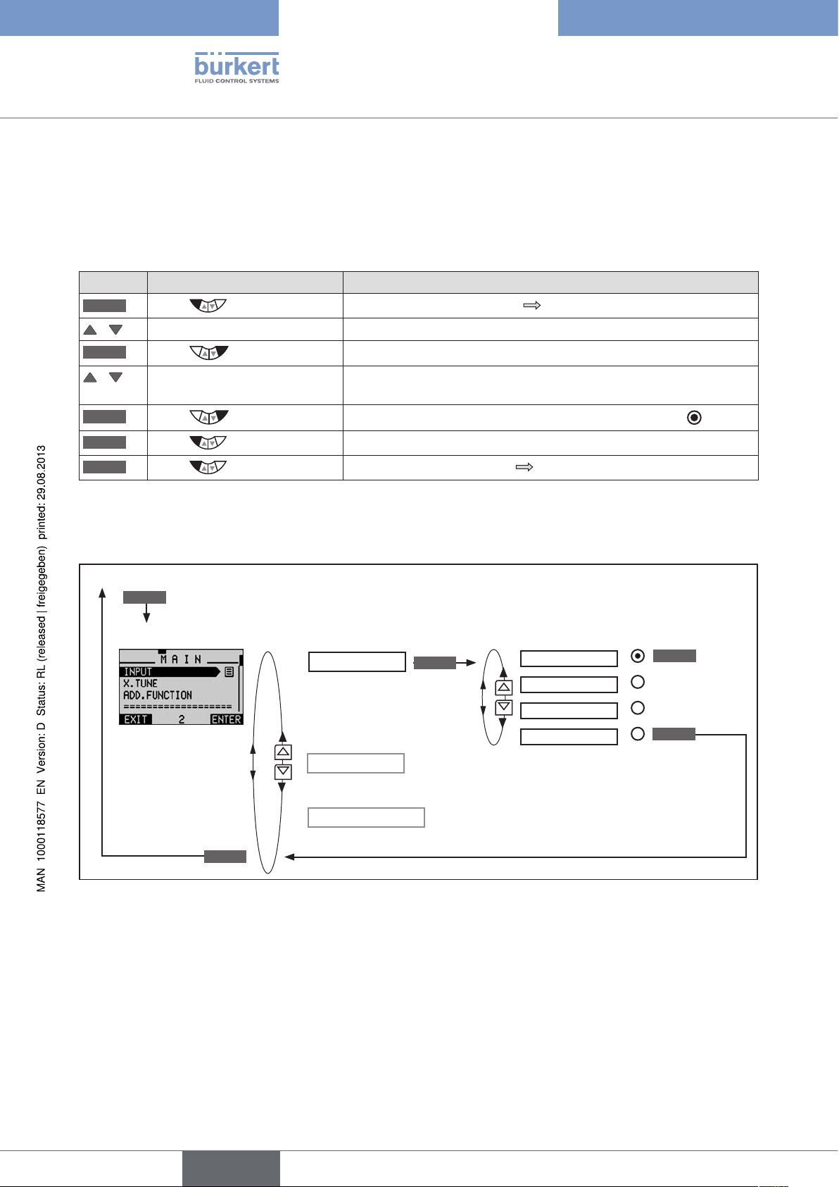
23.1. INPUT - Setting the input signal
This setting is used to select the input signal for the set-point variable.
Procedure:
Key Action Description
MENU
Press for approx. 3 s
/ Select INPUT
ENTER
Press
/ Select input signal
(4-20 mA, 0-20 mA,....)
SELEC
EXIT
EXIT
Table 33: Setting the input signal
Press
Press
Press
Switching from process level setting level.
The possible input signals for INPUT are displayed.
The selected input signal is now marked by a filled circle .
Return to the main menu (MAIN).
Switching from setting level process level.
Type 8792, 8793
Start-Up
Operating structure:
Process level (values are displayed)
MENU
Press for approx. 3 s
Setting level
EXIT
Figure 33: Operating structure INPUT
INPUT
X.TUNE
ADD.FUNCTION
ENTER
Select the input signal
4-20 mA
0-20 mA
0-10 V
0-5 V
SELEC
EXIT
78
English
Page 79
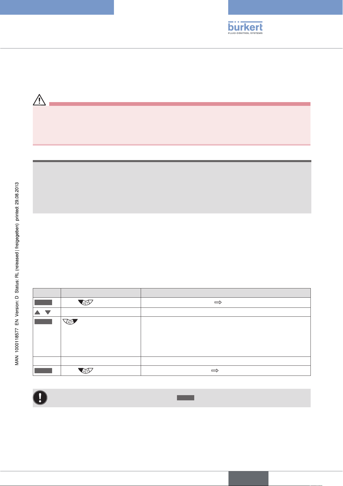
Type 8792, 8793
Start-Up
23.2. X.TUNE – Automatic adjustment of the position controller
WARNING!
Danger due to the valve position changing when the X.TUNE function is run!
When the X.TUNE function is run under operating pressure, there is an acute risk of injury.
• Never run X.TUNE while the process is running!
• Secure system against unintentional activation!
NOTE!
An incorrect supply pressure or incorrectly connected operating medium pressure may cause the
controller to be wrongly adjusted!
• Run X.TUNE in each case at the supply pressure available in subsequent operation (= pneumatic auxiliary
power).
• Run the X.TUNE function preferably without operating medium pressure to exclude interference due to flow
forces.
The following functions are actuated automatically:
• Adjustment of the sensor signal to the (physical) stroke of the actuator used.
• Determination of parameters of the PWM signals to control the solenoid valves integrated in type 8792/8793.
• Adjustment of the controller parameters for the position controller. Optimization occurs according to the criteria
of the shortest possible transient time without overshoots.
Procedure:
Key Action Description
MENU
Press for approx. 3 s
Switching from process level setting level.
/ Select X.TUNE
RUN
Hold down
as long as countdown (5 ...) is
running
While the automatic adjustment is running, messages on the
progress of the X.TUNE
(e.g. "TUNE #1....") are indicated on the display.
When the automatic adjustment ends, the message "X.TUNE READY"
is indicated.
Press any key Return to the main menu (MAIN).
EXIT
Table 34: Automatic adjustment of X.TUNE
Press
Switching from setting level process level.
To stop X.TUNE, press the left or right selection key
STOP
.
79
English
Page 80

Operating structure:
Process level (values are displayed)
MENU
Press for approx. 3 s
Setting level
Type 8792, 8793
Start-Up
INPUT
Automatic
self-parameterization
X.TUNE
RUN
Hold down
as long as
countdown
(5 ...) is
running
X.TUNE
STARTED
TUNE #0
INIT
X.TUNE
READY
EXIT
ADD.FUNCTION
EXIT
Figure 34: Operating structure X.TUNE
Automatically determining dead band DBND by running X.TUNE:
When X.TUNE is running, the dead band can be automatically determined depending on the friction
behavior of the actuating drive.
Before running X.TUNE, the X.CONTROL auxiliary function must be activated by incorporating it into the
main menu (MAIN).
If X.CONTROL is not activated, a fixed dead band of 1 % is used.
The changed data is saved in the memory (EEPROM) only when there is a switch to the process level,
by leaving the main menu (MAIN) using the left selection key
symbol is indicated
on the display.
EXIT
. During the save process, the save
80
Possible error messages when running X.TUNE:
Display Causes of error Remedial action
TUNE
err/break
X.TUNE locked
X.TUNE
Manual termination of self-parameterization
by pressing the
EXIT
key
The X.TUNE function is blocked Input access code
No compressed air connected Connect compressed air
ERROR 1
X.TUNE
ERROR 2
X.TUNE
ERROR 3
Compressed air failed during Autotune
(X.TUNE).
Actuator or control system deaeration side
leaking
Check compressed air supply
Not possible, device defective
English
Page 81

Type 8792, 8793
Start-Up
X.TUNE
Control system aeration side leaking Not possible, device defective
ERROR 4
X.TUNE
ERROR 5
The rotation range of the position sensor is
exceeded by 180°
Correct attachment of the position sensor
shaft on the actuator (see chapter "12.2"
and "12.3").
X.TUNE
ERROR 6
X.TUNE
ERROR 7
The end positions for POS-MIN and
POS-MAX are too close together
Incorrect assignment POS-MIN and
POS-MAX
Check compressed air supply
To determine POS-MIN and POS-MAX,
move the actuator in the direction indicated on the display.
X.TUNE
WARNING 1**
Potentiometer is not coupled optimally to
the actuator.
An optimum connection can provide a more
Set middle position as described
in chapter "12.2.4. Aligning lever
mechanism".
accurate position measurement
** Warning information gives tips on optimized operation. The device is operational even if this warning information is not
observed. Warning information is automatically hidden after several seconds.
Table 35: X.TUNE; possible error messages
After making the settings described in Chapters "23.1" and "23.2", the positioner (position controller) is ready for
use.
Activation and configuration of auxiliary functions is described in the following Chapter "26. Configuring the auxiliary functions".
23.2.1. X.TUNE.CONFIG – Manual configuration of X.TUNE
This function is needed for special requirements only.
For standard applications the X.TUNE function (automatic adjustment of the positioner), as described
above, is run using the factory default settings.
The description of the X.TUNE.CONFIG function can be found in Chapter "26.3. Manual configuration of X.TUNE".
English
81
Page 82

Type 8792, 8793
Start-Up
24. ACTIVATION OF THE PROCESS CONTROLLER
The process controller is activated by selecting the P.CONTROL auxiliary function
The activation transfers P.CONTROL into the main menu (MAIN) where it is available for further settings.
Procedure:
Key Action Description
MENU
/ Select ADD.FUNCTION
ENTER
/ Select P.CONTROL
ENTER
EXIT
Table 36: Activating auxiliary functions
Press for approx. 3 s
Press
Press
Press
Following activation of P.CONTROL, the P.Q‘LIN and P.TUNE menus are also available in the main menu
(MAIN). They offer support for the setting of the process control.
P.Q‘LIN
P.TUNE
Linearization of the process characteristic
Description see Chapter "25.4"
Self-optimization of the process controller (process tune)
Description see Chapter "25.5"
Switching from process level setting level.
The possible auxiliary functions are displayed.
P.CONTROL is now marked by a cross .
Acknowledgment and simultaneous return to the main menu (MAIN).
P.CONTROL is now activated and incorporated into the main menu.
ADD.FUNCTION menu.
in the
82
ADD.FUNCTION – Add auxiliary functions
Apart from activating the process controller, ADD.FUNCTION can be used to activate auxiliary functions and
incorporate them into the main menu.
The description can be found in Chapter "26. Configuring the auxiliary functions".
English
Page 83

Type 8792, 8793
Start-Up
25. BASIC SETTING OF THE PROCESS CONTROLLER
25.1. P.CONTROL – Setting up and parameterization of the process controller
To start up the process controller, you must make the following settings in the P.CONTROL menu:
1.
2.
Operating structure:
SETUP
PID.PARAMETER
P.CONTROL
Set up the process controller (configuration)
Parameterize process controller
ENTER ENTER
EXIT
PID.PARAMETER
SETUP
EXIT
ENTER
DBND 0.1 %
KP 0.00
TN 0.5
TV 0.0
X0 0.0 %
FILTER 0
PV-INPUT
PV SCALE
SP-INPUT
SP-SCALE*
EXIT
* The SP SCALE function is indicated only if the external set-point value default (external) menu option is activated under
SP INPUT.
Figure 35: Operating structure P.CONTROL
Key:
P.CO-INIT
① Insensitivity range (dead band) of the PID process controller
② Amplification factor of the process controller
③ Reset time
④ Hold-back time
⑤ Operating point
⑥ Filtering of the process actual value input
⑦ Indication of the signal type for process actual value (4 - 20 mA, frequency input, Pt 100 input)
⑧ Specification of the physical unit and scaling of the process actual value
⑨ Type of set-point value default (internal or external)
⑩ Scaling of the process set-point value (only for external set-point value default)
⑪ Enables a smooth switchover between AUTOMATIC and MANUAL mode
83
English
Page 84

Procedure:
Key Action Description
MENU
Press for approx. 3 s
Switching from process level setting level.
/ Select P.CONTROL Selection in the main menu (MAIN).
ENTER
Press
The submenu options for basic settings can now be selected.
1. Set up process controller (configuration)
/ Select SETUP
ENTER
Press
The menu for setting up the process controller is displayed. Set up
is described in Chapter "25.2. SETUP – Setting up the process
controller".
EXIT
Press
Return to P.CONTROL.
2. Parameterize process controller
/ Select PID.PARAMETER
ENTER
Press
The menu for parameterizing the process controller is displayed.
Parameterization is described in Chapter "25.3. PID.PARAMETER
– Parameterizing the process controller".
EXIT
EXIT
EXIT
Table 37: P.CONTROL; basic settings of the process controller
Press
Press
Press
Return to P.CONTROL.
Return to the main menu (MAIN).
Switching from setting level process level.
Type 8792, 8793
Start-Up
84
English
Page 85

Type 8792, 8793
Start-Up
25.2. SETUP – Setting up the process controller
These functions specify the type of control.
The procedure is described in the following Chapters "25.2.1" to "25.2.5".
25.2.1. PV-INPUT – Specifying signal type for the process actual value
One of the following signal types can be selected for the process actual value:
• Standard signal 4 ... 20 mA flow rate, pressure, level
• Frequency signal 0 ... 1000 Hz flow rate
• Circuit with Pt 100 -20 °C ... +220 °C temperature
Factory setting: 4 ... 20 mA
When the operating voltage has been switched on, the device looks for connected sensor types
(automatic sensor detection).
When a sensor type (PT 100 or 4 ... 20 mA) is detected, the signal type is automatically implemented in the
PV-INPUT operating menu.
If no sensor signal is detected, the last setting is retained.
The signal type frequency signal cannot be detected automatically, but must be set manually in the
PV-INPUT menu.
Operating structure:
SELEC
PV-INPUT 4-20 mA
ENTER
Standard signal 4–20 mA
(flow rate, pressure, level)
Frequency
Frequency signal 0 ... 1000 Hz
(flow rate)
EXIT
PT 100
Circuit with Pt 100
(temperature) -20 °C ... +220 °C
Figure 36: Operating structure PV-INPUT
Specifying signal type in the menu SETUP → PV-INPUT:
Key Action Description
/ Select PV-INPUT
ENTER
Press
The signal types are displayed.
/ Select signal type
SELEC
EXIT
Table 38: PV-INPUT; Specifying signal type
Press
Press
The selected signal type is now marked by a filled circle .
Return to SETUP.
85
English
Page 86

Type 8792, 8793
Start-Up
25.2.2. PV-SCALE – Scaling of the process actual value
The following settings are specified in the submenu of PV-SCALE:
PVmin
PVmax
K factor
Operating structure:
PV SCALE
ENTER
1. The physical unit of the process actual value.
2. Position of the decimal point of the process actual value.
3. Lower scaling value of the process actual value.
In PVmin the unit of the process actual value and the position of the decimal point are
specified for all scaling values (SPmin, SPmax, PVmin, PVmax).
Upper scaling value of the process actual value.
K-factor for the flow sensor
The menu option is available only for the frequency signal type (PV-INPUT → Frequency).
PVmin
INPUT
Select physical unit
Specify position of the decimal
point for all scaling values
Specify lower scaling value
OK
PVmax
INPUT
Specify upper scaling value
OK
*
*
86
Only for frequency signal type (PV-INPUT → Frequency)
EXIT
* If the submenu is left by pressing the left selection key
Figure 37: Operating structure PV-SCALE
K factor VALUE
INPUT INPUT
EXIT
Press for
approx. 5 s
TEACH-IN
ESC
, the value remains unchanged.
ENTER
Enter
K-factor
TEACH-IN
EXIT
Valve is being
closed
Container
is being filled
–> filling ...
Volume is
displayed
START
START
STOP
OK
OK
*
English
Page 87

Type 8792, 8793
Start-Up
25.2.2.1. Effects and dependencies of the settings of PV-INPUT on
PV-SCALE
The settings in the PV-SCALE menu have different effects, depending on the signal type selected in
PV-INPUT.
Even the selection options for the units of the process actual value (in PVmin) depend on the signal
type selected in PV-INPUT.
See following "Table 39"
Settings in the
submenu of
PV-SCALE
PVmin
PVmin
PVmax
Description of the effect Dependency on the signal type selected in
PV-INPUT
4 - 20 mA PT 100 Frequency
Selectable unit of the process
actual value for the physical
variables.
Adjustment range:
Flow rate, temperature,
pressure, length, volume.
(as well as ratio as % and
no unit)
0 ... 9999
(Temperature -200 ... 800)
Temperature Flow-rate
-200 ... 800 0 ... 9999
Specification of the reference range
for the dead band of the process
controller
Yes Yes Yes
(P.CONTROL → PID.PARAMETER
→ DBND).
Specification of the reference range
for the analog feedback (option).
See Chapter "26.2.14. OUTPUT –
Yes Yes Ye s
Configuring the outputs (option)".
Yes
see "Figure 38"
No No
K factor
Sensor calibration:
Sensor calibration: No No
Adjustment range: – – 0 ... 9999
Table 39: Effects of the settings in PV-SCALE depending on the signal type selected in PV-INPUT
Yes
see
"Figure 39"
Example of a sensor calibration for signal type 4 - 20 mA:
Scaling value
[l/min]
10
Process actual value
PVmax
SPmax
Process set-point
value
PVmin
0
SPmin
Figure 38: Example of a sensor calibration for signal type 4 - 20 mA
4
20
Input
signal [mA]
Scaling:
Process actual value from the transmitter:
4 ... 20 mA corresponds to 0 ... 10 l/min
Process set-point value from PLC:
4 ... 20 mA corresponds to 0 ... 8 l/min
87
English
Page 88
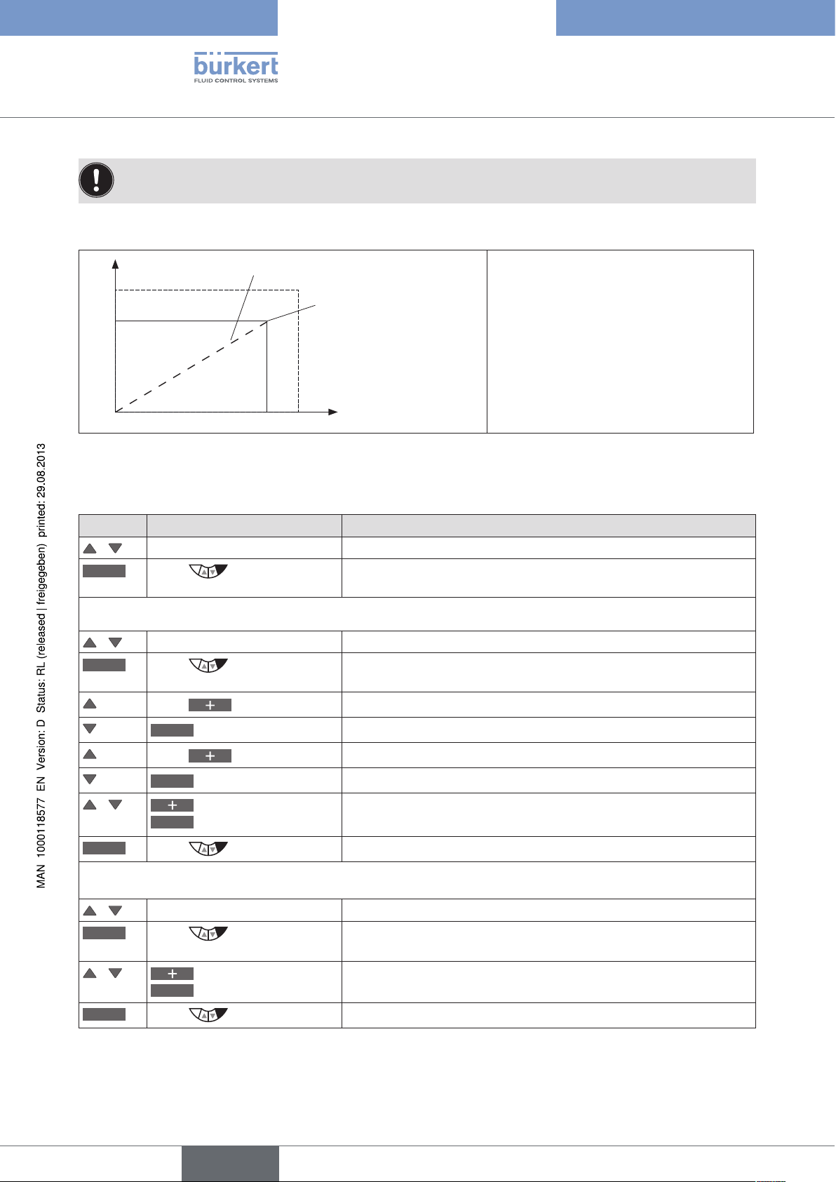
Type 8792, 8793
Start-Up
For internal set-point value default (SP-INPUT → internal), the process set-point value is input directly on
the process level.
Example of a sensor calibration for frequency signal type:
100
Pulses
Flow-rate
K-factor
(pulses/liter)
Scaling:
Process actual value:
100 pulses correspond to 10 liters
Process set-point value:
K-factor 1.25 correspond to 8 liters
0
Figure 39: Example of a sensor calibration for frequency signal type
10
Liters
Scaling of the process actual value in the menu SETUP → PV-SCALE:
Key Action Description
/ Select PV-SCALE Selection in the main menu (MAIN).
ENTER
Press
The submenu options for scaling of the process actual value are
displayed.
1. Setting PVmin
/ Select PVmin
INPUT
Press
The input screen is opened. First specify the physical unit which has
a dark background.
Select physical unit.
The decimal point has a dark background.
Specify position of the decimal point.
The last digit of the scaling value has a dark background.
Set scaling value (lower process actual value).
/
Press (x times)
<–
Select decimal point
Press (x times)
<–
Select scaling value
Increase value
<–
Select decimal place
88
OK
Press
2. Setting PVmax
/ Select PVmax
INPUT
/
OK
Press
<–
Press
Increase value
Select decimal place
Return to PV-SCALE.
The input screen is opened. The last digit of the scaling value has a
dark background.
Set scaling value (upper process actual value).
Return to PV-SCALE.
English
Page 89

Type 8792, 8793
Start-Up
Key Action Description
3. Setting K-factor (only available for frequency signal type)
/ Select K-factor
ENTER
Press
The submenu for the setting of the K-factor is displayed.
either
/
INPUT
Select VALUE
Press
Manual input of the K-factor.
The input screen is opened. The decimal point has a dark
background.
Specify position of the decimal point.
The last digit of the value has a dark background.
Set K-factor.
/
Select decimal point
<–
Select value
<–
Select decimal place
Increase value
OK
Press
Return to K-factor.
or
/ Select TEACH-IN
ENTER
START
STOP
Press for approx. 5 s
Press
Press
Calculating the K-factor by measuring a specific flow rate.
The valve is being closed.
The container is being filled.
The measured volume is displayed and the input screen is opened.
The decimal point has a dark background.
Specify position of the decimal point.
The last digit of the value has a dark background.
Set the measured volume.
/
Select decimal point
<–
Select value
<–
Select decimal place
Increase value
OK
EXIT
EXIT
EXIT
Table 40: PV-SCALE; scaling process actual value
Press
Press
Press
Press
Return to TEACH-IN.
Return to K-factor.
Return to PV-SCALE.
Return to SETUP.
If the submenu is left by pressing the left selection key
ESC
, the value remains unchanged.
English
89
Page 90

Type 8792, 8793
Start-Up
25.2.3. SP-INPUT – Type of the set-point value default (internal or external)
The SP-INPUT menu specifies how the default of the process set-point value is to be implemented.
• Internal: Input of the set-point value on the process level
• External: Default of the set-point value via the standard signal input
Operating structure:
SELEC
SP-INPUT internal
ENTER
Set-point value default, internal
Input the process set-point value on the process
level
EXIT
external
Set-point value default, external
Default of the process set-point value via the
standard signal input
Figure 40: Operating structure PV-INPUT
Specify type of set-point value default in the menu SETUP → SP-INPUT:
Key Action Description
/ Select SP-INPUT
ENTER
Press
The types of set-point value default are displayed.
/ Select the type of set-point
value default
SELEC
EXIT
Table 41: SP-INPUT; specifying type of the set-point value default
Press
Press
The selection is marked by a filled circle .
Return to SETUP.
For internal set-point value default (SP-INPUT → internal), the process set-point value is input directly on
the process level.
90
25.2.4. SP-SCALE – Scaling of the process set-point value (for external set-point value default only)
The SP-SCALE menu assigns the values for the lower and upper process set-point value to the particular current
or voltage value of the standard signal.
The menu is available for external set-point value default only (SP-INPUT → external).
For internal set-point value default (SP-INPUT → internal), there is no scaling of the process set-point
value via SPmin and SPmax.
The set-point value is input directly on the process level. The physical unit and the position of the decimal
point are specified during the scaling of the process actual value (PV-SCALE → PVmin).
For description see Chapter "25.2.2. PV-SCALE – Scaling of the process actual value", page 86
English
Page 91

Type 8792, 8793
Operating structure:
Start-Up
SP-SCALE
Figure 41: Operating structure SP-SCALE
ENTER
EXIT
SPmin
SPmax
INPUT
INPUT
Scaling process set-point value SETUP → SP-SCALE:
Key Action Description
/ Select SP-SCALE
ENTER
Press
The submenu options for scaling of the process set-point value are
displayed.
/ Select SPmin
INPUT
/
Press
<–
Increase value
Select decimal place
The input screen is opened.
Set scaling value (lower process set-point value).
The value is assigned to the smallest current or voltage value of the
standard signal.
OK
Press
Return to SP-SCALE.
/ Select SPmax
INPUT
/
Press
<–
Increase value
Select decimal place
The input screen is opened.
Set scaling value (upper process set-point value).
The value is assigned to the largest current or voltage value of the
standard signal.
OK
EXIT
Table 42: SP-SCALE; scaling process set-point value
Press
Press
Return to SP-SCALE.
Return to SETUP.
Input lower process set-point
value
Input upper process set-point
value
OK
OK
*
*
If the submenu is left by pressing the left selection key
ESC
, the value remains unchanged.
English
91
Page 92

Type 8792, 8793
Start-Up
25.2.5. P.CO-INIT – Smooth switchover MANUAL-AUTOMATIC
The smooth switchover between the MANUAL and AUTOMATIC states can be activated or deactivated in the
P.CO-INIT menu.
Factory default setting:
bumpless
Smooth switchover activated.
Operating structure:
SELEC
P.CO-INIT bumpless
Figure 42: Operating structure P.CO-INIT
ENTER
EXIT
standard
Smooth
Smooth
Procedure:
Key Action Description
/ Select P.CO-INIT
ENTER
Press
/ Select required function bumpless =
The selection (bumpless) and (standard) is displayed.
smooth
standard = smooth switchover deactivated
SELEC
EXIT
Table 43: P.CO-INIT; smooth switchover MANUAL-AUTOMATIC
Press
Press
The selection is marked by a filled circle .
Return to SETUP.
switchover activated
switchover deactivated
switchover activated
92
English
Page 93
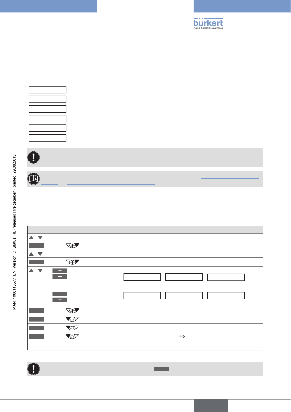
Type 8792, 8793
Start-Up
25.3. PID.PARAMETER – Parameterizing the process controller
The following control parameters of the process controller are manually set in this menu.
DBND 1.0 %
KP 1.00
TN 999.0
TV 0.0
X0 0.0 %
FILTER 0
Insensitivity range (dead band) of the process controller
Amplification factor of the (P-contribution of the PID controller)
Reset time (I-contribution of the PID controller)
Hold-back time (D-contribution of the PID controller)
Operating point
Filtering of the process actual value input
The automatic parameterization of the PID controller integrated in the process controller
(menu options KP, TN. TV) can be implemented with the aid of the P.TUNE function
(see Chapter "25.5. P.TUNE – Self-optimization of the process controller").
Basic information for setting the process controller can be found in Chapters "40. Properties of PID Controllers" and "41. Adjustment rules for PID Controllers".
25.3.1. Procedure for inputting the parameters
The settings in the PID.PARAMETER menu are always made in the same way.
Procedure:
Key Action Description
/ Select PID.PARAMETER
ENTER
Press
/ Select menu option
INPUT
/
Press
Increase value
Reduce value
or
<–
Select decimal place
Increase value
The menu for parameterizing the process controller is displayed.
The input screen is opened.
Set value when
DBND X.X %
*
X0 0 %
/
FILTER 5
/
Set value when
KP X.XX
*
TN X.0 sec
/
TV 1.0 sec
/
:
:
OK
EXIT
EXIT
EXIT
* The description of the submenus of PID.PARAMETER can be found in the following chapters.
Table 44: PID.PARAMETER; parameterizing process controller
Press
Press
Press
Press
If the submenu is left by pressing the left selection key
Return to PID.PARAMETER.
Return to P.CONTROL.
Return to the main menu (MAIN).
Switching from setting level process level.
ESC
, the value remains unchanged.
English
93
Page 94

Type 8792, 8793
Start-Up
25.3.2. DBND – Insensitivity range (dead band)
This function causes the process controller to respond from a specific control difference only. This protects both
the solenoid valves in Type 8792/8793 and the pneumatic actuator.
Factory setting: 1.0 % with reference to the range of the scaled process actual value
(setting in the menu PV-SCALE → PVmin → PVmax).
Operating structure:
PID.PARAMETER
Figure 43: Operating structure DBND; insensitivity range
ENTER INPUT
EXIT
DBND 1.0 %
FILTER 0
Insensitivity range for process control
Xd2‘
Process
set-point value
(SP)
Control
difference
Xd2
Process
actual value
(PV)
Figure 44: Diagram DBND; insensitivity range for process control
Input value
Xd2
Dead band
OK
ESC
to the controller
Xd2‘
94
25.3.3. KP – Amplification factor of the process controller
The amplification factor specifies the P-contribution of the PID controller
(can be set with the aid of the P.TUNE function).
Factory setting: 1.00
Operating structure:
PID.PARAMETER
Figure 45: Operating structure KP; amplification factor
ENTER
EXIT
The KP amplification of the process controller refers to the scaled, physical unit.
English
DBND 1.0 %
KP 1.00
FILTER 0
INPUT
Input value
Adjustment range: 0 ... 99.99
(% / set unit)
OK
ESC
Page 95

Type 8792, 8793
Start-Up
25.3.4. TN – Reset time of the process controller
The reset time specifies the I-contribution of the PID controller
(can be set with the aid of the P.TUNE function).
Factory setting: 999.9 s
Operating structure:
PID.PARAMETER
Figure 46: Operating structure TN; reset time
ENTER
EXIT
DBND 1.0 %
TN 999.9
FILTER 0
INPUT
Input value
Adjustment range: 0.5 ... 999.9 s
25.3.5. TV – Hold-back time of the process controller
The hold-back time specifies the D-contribution of the PID controller
(can be set with the aid of the P.TUNE function).
Factory setting: 0.0 s
Operating structure:
PID.PARAMETER
ENTER
EXIT
DBND 1.0 %
TV 0.0
FILTER 0
INPUT
Input value
Adjustment range: 0 ... 999.9 s
OK
ESC
OK
ESC
Figure 47: Operating structure TV; hold-back time
25.3.6. X0 – Operating point of the process controller
The operating point corresponds to the size of the proportional portion when control difference = 0.
Factory setting: 0.0 %
Operating structure:
PID.PARAMETER
Figure 48: Operating structure X0; operating point
ENTER
EXIT
DBND 1.0 %
X0 0.0 %
FILTER 0
INPUT
Input value
Adjustment range: 0 ... 100 %
English
OK
ESC
95
Page 96

Type 8792, 8793
Start-Up
25.3.7. FILTER – Filtering of the process actual value input
The filter is valid for all process actual value types and has a low pass behavior (PT1).
Factory setting: 0
Operating structure:
PID.PARAMETER
ENTER
EXIT
DBND 1.0 %
FILTER 0
INPUT
Input value
Adjustment range: 0 ... 9
Figure 49: Operating structure FILTER; filtering of the process actual value input
Setting the filter effect in 10 stages
Setting Corresponds to cut-off frequency (Hz) Effect
0 10 Lowest filter effect
1 5
2 2
3 1
4 0.5
5 0.2
6 0.1
7 0.07
8 0.05
9 0.03 Largest filter effect
Table 45: Setting the filter effect
OK
ESC
96
On page 251 you will find a table for entering your set parameters.
English
Page 97

Type 8792, 8793
Start-Up
25.4. P.Q‘LIN – Linearization of the process characteristic
This function automatically linearizes the process characteristic.
In doing so, the nodes for the correction characteristic are automatically determined. To do this, the program moves
through the valve stroke in 20 steps and measures the associated process variable.
The correction characteristic and the associated value pairs are saved in the menu option CHARACT → FREE.
This is where they can be viewed and freely programmed. For a description see Chapter "26.2.1".
If the CARACT menu option has still not been activated and incorporated into the main menu (MAIN), this will happen
automatically when P.Q‘LIN is being run.
Run P.Q‘LIN:
Key Action Description
/ Select P.Q‘LIN The function is in the main menu (MAIN) after activation of
P.CONTROL.
RUN
Hold down as long as
countdown (5 ...) is running
The following displays are indicated on the display:
Q‘LIN #0
CMD=0%
P.Q‘LIN is started.
Display of the node which is currently running (progress is indicated by a progress bar along the upper edge of the display).
Q.LIN #1
CMD=10%
... continuing to
Q.LIN #10
CMD=100%
Q.LIN
Automatic linearization was successfully completed.
ready
EXIT
Table 46: P.Q‘LIN; Automatic linearization of the process characteristic
Press
Return to the main menu (MAIN).
Possible error messages when running P.Q‘LIN:
Display Cause of fault Remedial action
Q.LIN
err/break
P.Q‘LIN
ERROR 1
Manual termination of linearization by
pressing the
EXIT
key.
No supply pressure connected. Connect supply pressure.
No change to process variable. Check process and, if required, switch on
pump or open the shut-off valve.
Check process sensor.
P.Q‘LIN
ERROR 2
Failure of the supply pressure while
P.Q’LIN running.
Automatic adjustment of the X.TUNE
Check supply pressure.
Run X.TUNE.
position controller not run.
Table 47: P.Q‘LIN; possible error messages
97
English
Page 98

Type 8792, 8793
Start-Up
25.5. P.TUNE – Self-optimization of the process controller
This function can be used to automatically parameterize the PID controller integrated in the process controller.
In doing so, the parameters for the P, I and D-contribution of the PID controller are automatically determined and
transferred to the corresponding menus of (KP, TN, TV). This is where they can be viewed and changed.
Explanation of the PID controller:
The control system of Type 8793 has an integrated PID process controller. Any process variable, such as flow rate,
temperature, pressure, etc., can be controlled by connecting an appropriate sensor.
To obtain good control behavior, the structure and parameterization of the PID controller must be adjusted to the
properties of the process (controlled section).
This task requires control experience as well as measuring instruments and is time-consuming. The P.TUNE function
can be used to automatically parameterize the PID controller integrated in the process controller.
Basic information for setting the process controller can be found in Chapters "40. Properties of PID Controllers" and "41. Adjustment rules for PID Controllers".
25.5.1. The mode of operation of P.TUNE
The P.TUNE function automatically identifies the process. To do this, the process is activated with a defined
disturbance variable. Typical process characteristics are derived from the response signal and the structure and
parameters of the process controller are determined on the basis of the process characteristics.
When using P.TUNE self-optimization, optimum results are obtained under the following conditions:
• Stable or stationary conditions concerning the process actual value PV when starting P.TUNE.
• Execution of P.TUNE in the operating point or within the operating range of the process control.
25.5.2. Preparatory measure for execution of P.TUNE
The measures described below are not compulsory conditions for execution of the function P.TUNE.
However, they will increase the quality of the result.
The P.TUNE function can be run in the MANUAL or AUTOMATIC operating state.
98
When P.TUNE is complete, the control system is in the operating state which was set previously.
English
Page 99

Type 8792, 8793
Start-Up
25.5.2.1. Preparatory measures for execution of P.TUNE in the MANUAL
operating state
Moving process actual value PV to the operating point:
Key Action Description
Setting on the process level:
/ Select PV The process actual value PV is indicated on the display.
MANU
Press
Open valve
Close valve
OPN
CLS
or
As soon as the process actual value PV is constant, the P.TUNE function can be started.
Table 48: P.TUNE; preparatory measure for running X.TUNE in the MANUAL operating state
Change to MANUAL operating state.
The input screen for manually opening and closing the valve is
displayed.
By opening or closing the control valve, move the process actual
value to the required operating point.
25.5.2.2. Preparatory measure for execution of P.TUNE in the
AUTOMATIC operating state
By inputting a process set-point value SP, move the process actual value PV to the operating point.
Observe the internal or external set-point value default for the input
(P,CONTROL → SETUP → SP-INPUT → internal/external):
For internal set-point value default: Input the process set-point value SP via the device keyboard
see description below "Table 49" ).
For external set-point value default: Input the process set-point value SP via the analog set-point value
input.
Inputting a process set-point value:
Key Action Description
Setting on the process level:
/ Select SP The process set-point value is indicated on the display.
INPUT
Press
/ Input value
<–
Select decimal place
Increase value
OK
Table 49: P.TUNE; preparatory measure for running X.TUNE in the AUTOMATIC operating state
Press
The input screen for inputting the process set-point value is
displayed.
The selected set-point value SP should be near the future operating
point.
Acknowledge input and return to the display of SP.
The process variable PV is changed according to the set-point value default based on the factory default PID
parameters.
→ Before running the P.TUNE function, wait until the process actual value PV has reached a stable state.
English
99
Page 100

Type 8792, 8793
Start-Up
To observe PV, it is recommended to select via the arrow keys / the graphical display SP/PV(t).
To be able to select the display SP/PV(t), it must be activated in the EXTRAS menu
(see Chapter
"26.2.18. EXTRAS – Setting the display".
→ If PV oscillates continuously, the preset amplification factor of the process controller KP in the
menu P.CONTROL → PID.PARAMETER should be reduced.
→ As soon as the process actual value PV is constant, the P.TUNE function can be started.
25.5.3. Starting the function P.TUNE
WARNING!
Risk of injury from uncontrolled process!
While the P.TUNE function is running, the control valve automatically changes the current degree of opening
and intervenes in the running process.
• Using suitable measures, prevent the permitted process limits from being exceeded.
For example by:
- an automatic emergency shutdown
- stopping the P.TUNE function by pressing the STOP key (press left or right key).
Procedure:
Key Action Description
MENU
Press for approx. 3 s
Switching from process level setting level
/ Select P.TUNE
RUN
Hold down
as long as countdown (5 ...) is
running
During the automatic adjustment the following messages are indicated on the display.
"starting process tune" - Start self-optimization.
"identifying control process" - Process identification. Typical
process variables are determined from the response signal to a
defined stimulus.
"calculating PID parameters" - Structure and parameters of the
process controller are determined.
"TUNE ready" - Self-optimization was successfully completed.
Press any key Return to the main menu (MAIN).
EXIT
Table 50: Automatic adjustment of X.TUNE
Press
Switching from setting level process level.
100
To stop P.TUNE, press the left or right selection key
STOP
.
The changed data is saved in the memory (EEPROM) only when there is a switch to the process level,
by leaving the main menu (MAIN) using the left selection key
symbol is indicated
on the display.
EXIT
. During the save process, the save
English
 Loading...