

Page 1
Type 8x92, 8x93
Positioner / Process controller
- Software Tool for Communication
Software Tool for Communication for Positioner / Process controller
Kommunikationssoftware für Positioner / Prozessregler
Logiciel de communication pour positionneur / régulateur de process
Supplement to Operating Instructions
Ergänzung zur Bedienungsanleitung
Complément aux manuel d‘utilisation
Page 2

We reserve the right to make technical changes without notice.
Technische Änderungen vorbehalten.
Sous réserve de modifications techniques.
© 2013 Bürkert Werke GmbH
Operating Instructions 1301/01_EU-ML_00810024 / Original DE
Page 3
Software Tool - 8x92 / 8x93
Communication software (Software Tool)
for positioner / process controller
Table of ConTenTs
1. SUPPLEMENTARY OPERATING INSTRUCTIONS ..............................................................................................................6
1.1. Symbols ......................................................................................................................................................................................6
2. GENERAL INFORMATION ................................................................................................................................................................7
2.1. Contact address .....................................................................................................................................................................7
2.2. Information on the internet ...............................................................................................................................................7
3. PRODUCT DESCRIPTION ...............................................................................................................................................................8
3.1. Required components .........................................................................................................................................................8
3.1.1. Windows 2000, XP, Vista ....................................................................................................................... 8
3.1.2. Windows XP, Vista, 7 ............................................................................................................................... 8
3.2. Definitions of terms for PACTware / FDT / DTM ..................................................................................................8
4. CONTROL AND DISPLAY ELEMENTS ......................................................................................................................................9
4.1. Overview of screen display ..............................................................................................................................................9
4.2. PACTware control and display elements ...............................................................................................................10
4.2.1. Toolbar .......................................................................................................................................................10
4.2.2. Status bar ..................................................................................................................................................11
4.3. Control and display elements of Bürkert DTMs .................................................................................................12
4.3.1. Toolbar .......................................................................................................................................................12
4.3.2. Status bar ..................................................................................................................................................12
4.3.3. Navigation area and work area .............................................................................................................13
4.3.4. Buttons for data transfer ........................................................................................................................14
4.3.5. Icons ...........................................................................................................................................................14
5. INSTALLATION ...................................................................................................................................................................................15
5.1. System requirements .......................................................................................................................................................15
5.2. Installing PACTware and DTMs ...................................................................................................................................16
5.2.1. PACTware version 3.6 and .NET Framework 1.1 including SP1 .................................................16
5.2.2. PACTware version 4.1 and .NET Framework 2.0 ............................................................................17
5.2.3. Bürkert device DTM ................................................................................................................................18
English
3
Page 4

Software Tool - 8x92 / 8x93
6. OPERATION AND FUNCTION ....................................................................................................................................................19
6.1. Starting PACTware .............................................................................................................................................................19
6.2. Creating a project ...............................................................................................................................................................19
6.2.1. General description ................................................................................................................................19
6.2.2. Creating a project for Bürkert positioners .........................................................................................21
6.3. Basic settings .......................................................................................................................................................................24
6.3.1. Activation of device DTMs .....................................................................................................................24
6.3.2. Device identification................................................................................................................................26
6.3.3. Running the automatic adjustment for TUNE FUNCTIONS ................................................... 27
6.4. Transferring parameters ..................................................................................................................................................29
6.4.1. Reading parameters from the device ..................................................................................................29
6.4.2. Write parameters to the device ............................................................................................................30
6.5. Parameterization .................................................................................................................................................................30
6.5.1. Parameterizing functions .......................................................................................................................31
6.6. Error messages ...................................................................................................................................................................32
6.6.1. Error messages while the X.TUNE function is running ................................................................ 32
6.6.2. Error messages while the PQ.LIN function is running ...................................................................32
6.6.3. Error messages while the P.TUNE function is running ..................................................................33
7. BASIC FUNCTIONS .........................................................................................................................................................................34
7.1. Overview of basic functions ..........................................................................................................................................34
7.2. Basic functions - parameter .........................................................................................................................................34
7.3. Basic functions - setting parameter .........................................................................................................................35
7.3.1. ACTUATOR -
Inputting the operating mode of the pneumatic actuator ...............................................................35
7.3.2. INPUT -
Enter the standard signal .......................................................................................................................35
7.3.3. BUS.COMM -
Adjust the selection / parameters of the field bus interface ..........................................................36
7.3.4. RESET -
Reset to factory settings ........................................................................................................................36
7.3.5. TUNE FUNCTIONS -
Automatic adjustment of the positioner / process controller to the relevant
operating conditions ...............................................................................................................................36
4
English
Page 5

Software Tool - 8x92 / 8x93
8. AUXILIARY FUNCTIONS ...............................................................................................................................................................37
8.1. Overview of auxiliary functions ...................................................................................................................................37
8.2. Adding auxiliary functions (ADD.FUNCTION) ......................................................................................................38
8.3. Removing auxiliary functions (ADD.FUNCTION) ................................................................................................38
8.4. Auxiliary functions - parameter....................................................................................................................................... 39
8.5. Auxiliary functions - setting parameter ...................................................................................................................39
9. DEINSTALLATION OF PACTWARE/ DTMS..........................................................................................................................40
9.1. Deinstallation process ......................................................................................................................................................40
English
5
Page 6
Software Tool - 8x92 / 8x93
Supplementary operating instructions
1. SUPPLEMENTARY OPERATING
INSTRUCTIONS
The supplementary operating instructions describe the communication software for positioner / process controller
TopControl and SideControl.
Safety Information!
Safety instructions and information for using the device may be found in the corresponding operating
instructions.
• The operating instructions must be read and understood.
1.1. Symbols
DANGER!
Warns of an immediate danger!
• Failure to observe the warning will result in a fatal or serious injury.
WARNING!
Warns of a potentially dangerous situation!
• Failure to observe the warning may result in serious injuries or death.
CAUTION!
Warns of a possible danger!
• Failure to observe this warning may result in a moderate or minor injury.
NOTE!
Warns of damage to property!
• Failure to observe the warning may result in damage to the device or the equipment.
Indicates important additional information, tips and recommendations.
Refers to information in these operating instructions or in other documentation.
→ Designates a procedure which you must carry out.
6
English
Page 7
Software Tool - 8x92 / 8x93
General information
2. GENERAL INFORMATION
2.1. Contact address
Germany
Bürkert Fluid Control Systems
Sales Center
Chr.-Bürkert-Str. 13-17
D-74653 Ingelfingen
Tel. + 49 (0) 7940 - 10 91 111
Fax + 49 (0) 7940 - 10 91 448
E-mail: info@de.buerkert.com
International
Contact addresses can be found on the final pages of the printed operating instructions.
And also on the Internet at:
www.burkert.com
2.2. Information on the internet
The operating instructions and data sheets for device types can be found on the Internet at:
www.burkert.com
English
7
Page 8

3. PRODUCT DESCRIPTION
3.1. Required components
3.1.1. Windows 2000, XP, Vista
• Microsoft .NET Framework 1.1
• Microsoft .NET Framework 1.1 Service Pack 1
• PACTware Version 3.6
including HART protocol driver from Codewrights GmbH
• Bürkert device DTM
"8692 Positioner TopControl"
"8693 Process controller TopControl"
"8792 Positioner SideControl"
“8793 Process controller SideControl”
Software Tool - 8x92 / 8x93
Product description
• Firmware Version C.01 or higher for types 8692 and 8693 or B.01 or higher for types 8792 and 8793
• Adapter USB-RS232, ID number 227093 (HART communication on the 4/20 mA interface is not possible).
3.1.2. Windows XP, Vista, 7
• Microsoft .NET Framework 2.0
• PACTware Version 4.1
including HART protocol driver from Codewrights GmbH
• Bürkert device DTM
“8692 Positioner TopControl”
“8693 Process controller TopControl”
“8792 Positioner SideControl”
“8793 Process controller SideControl”
• Firmware Version C.01 or higher for types 8692 and 8693 or B.01 or higher for types 8792 and 8793
• Adapter USB-RS232, ID number 227093 (HART communication on the 4/20 mA interface is not possible).
3.2. Definitions of terms for PACTware / FDT / DTM
PACTware (Process Automation Configuration Tool):
Manufacturer- and field bus-independent software for start-up, operation, and maintenance of all types of field
devices. This general product series includes the DTMs (Device Type Managers) of the corresponding field device
manufacturers. They are integrated according to interface specification FDT 1.20.
Therefore a DTM belonging to the relevant device type is always required to operate a field device.
FDT (Field Device Tool):
Standardized interface description; defines data exchange between the various DTMs and the frame application,
for example PACTware.
DTM (Device Type Manager):
The DTM is the actual control module of actuators, sensors, and field components. It includes all specific data and
functions of a specific device type and returns all elements and dialogs needed for operation.
8
A DTM is only capable of running within a frame program such as PACTware.
English
Page 9
Software Tool - 8x92 / 8x93
Control and display elements
4. CONTROL AND DISPLAY ELEMENTS
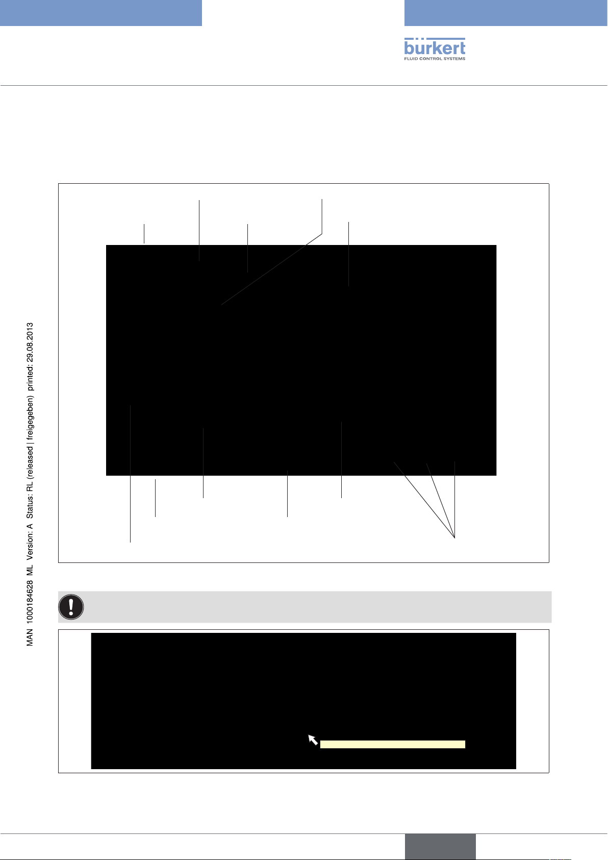
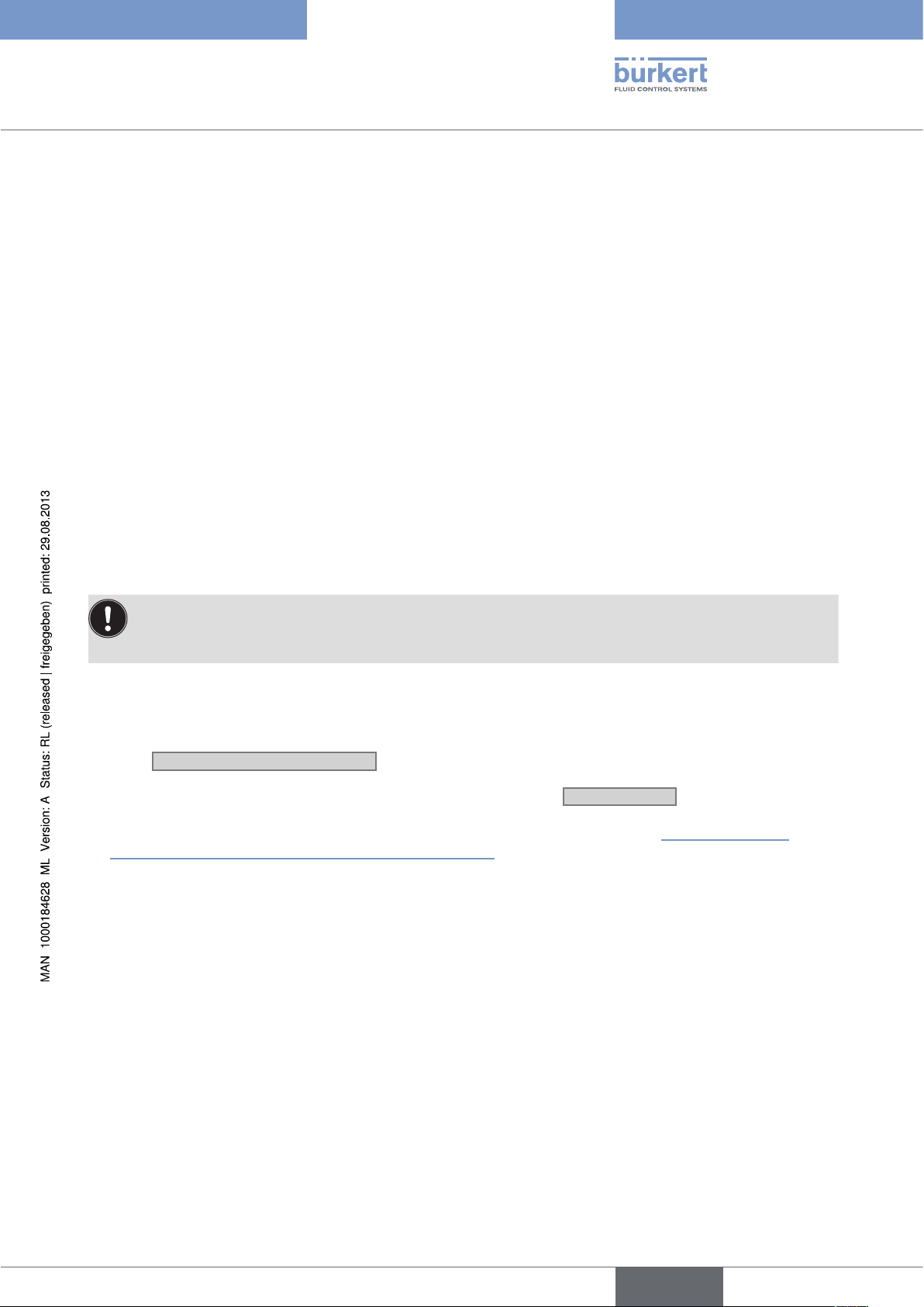
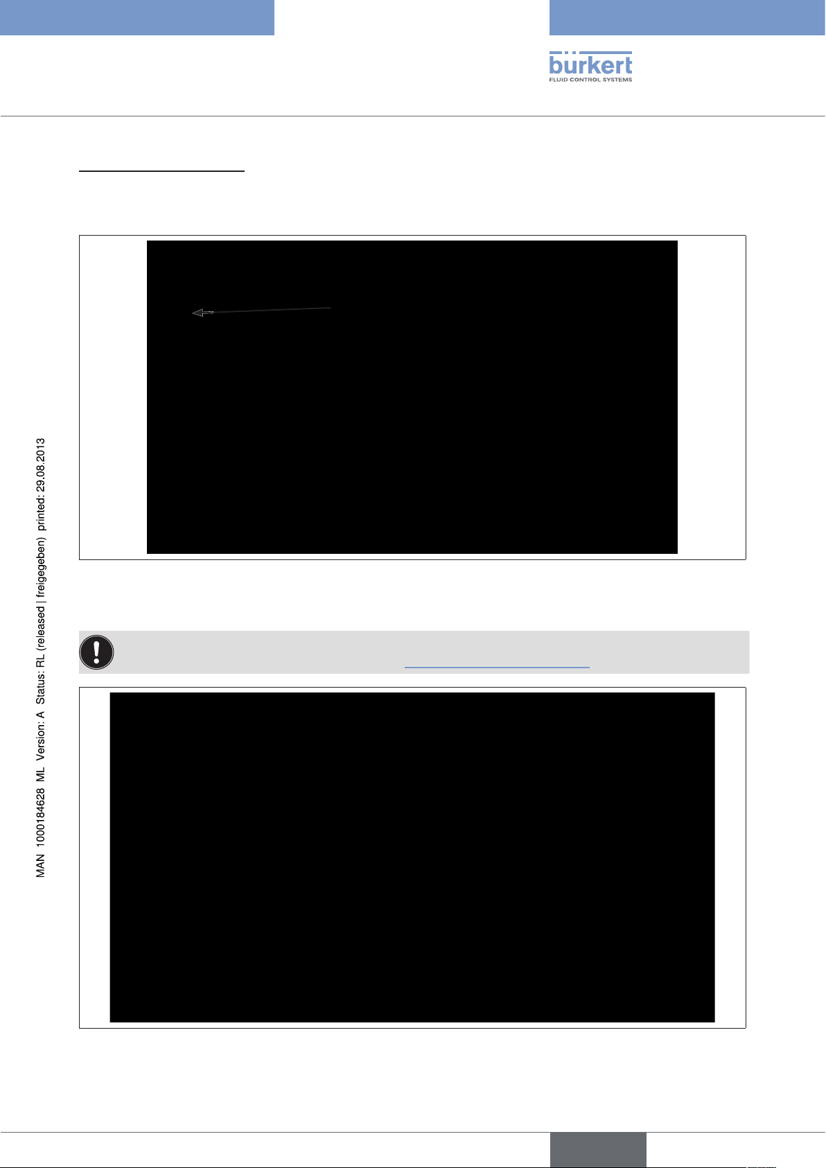
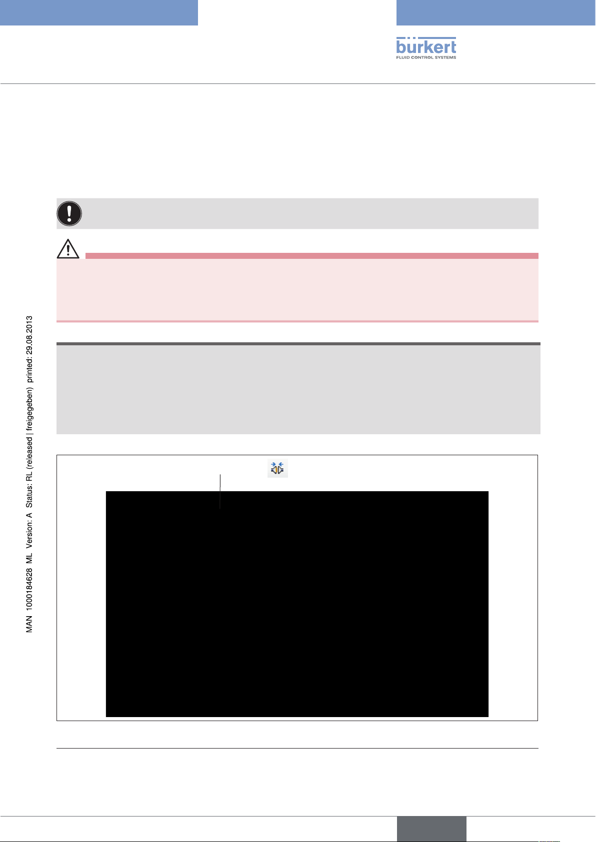
4.1. Overview of screen display
PACTware toolbar
PACTware window
DTM window
DTM toolbar
Identification area
Navigation area
PACTware status bar
Project window
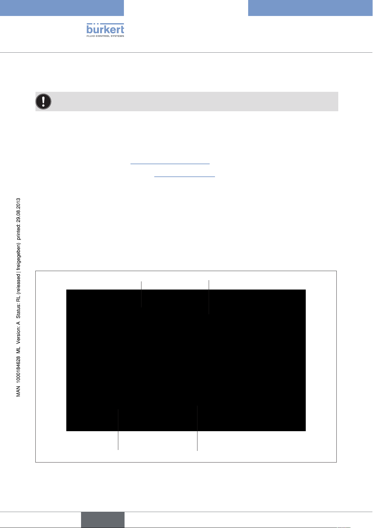
Figure 1: Overview of screen display
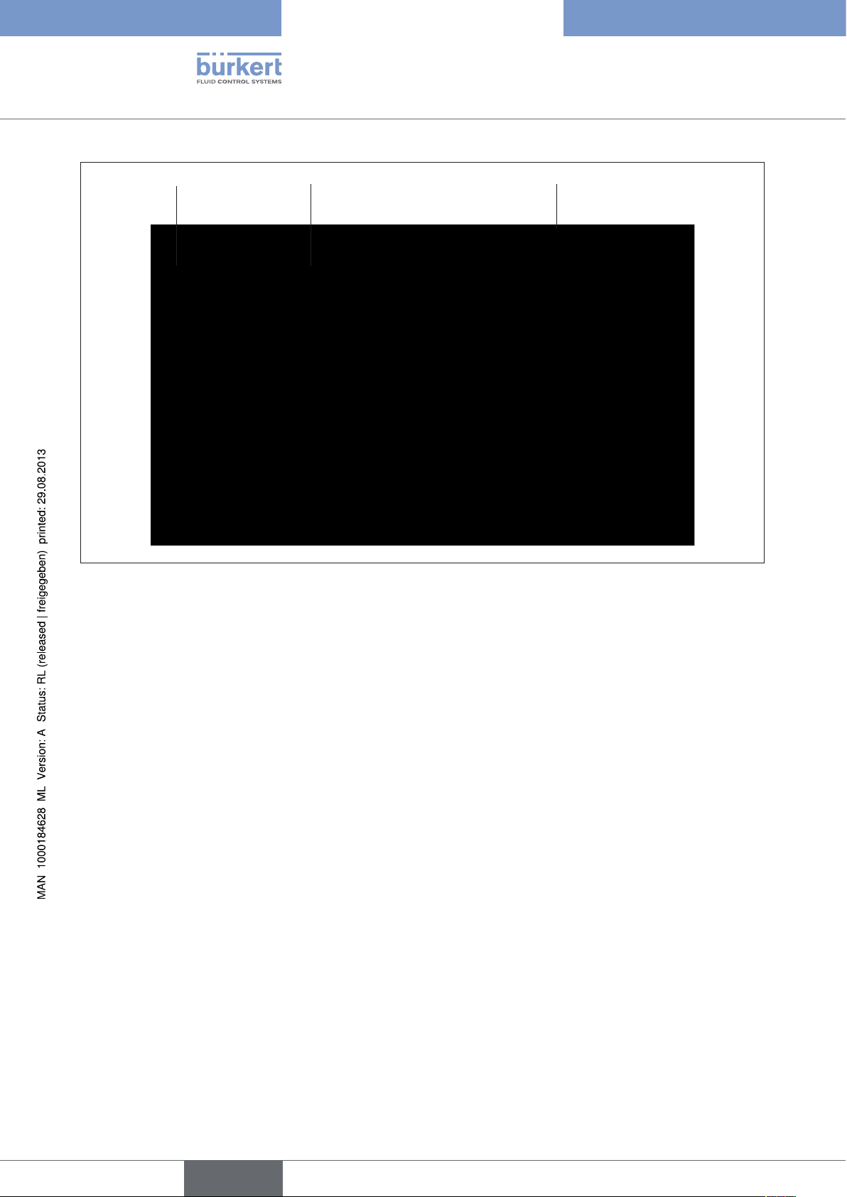
Many icons and parameter have Tooltips (brief explanation) which clarify the function.
Figure 2: Tooltip
DTM status bar
Work area
Operating mode of actuator (single- or double-acting)
Buttons
9
English
Page 10
Software Tool - 8x92 / 8x93
Control and display elements
4.2. PACTware control and display elements
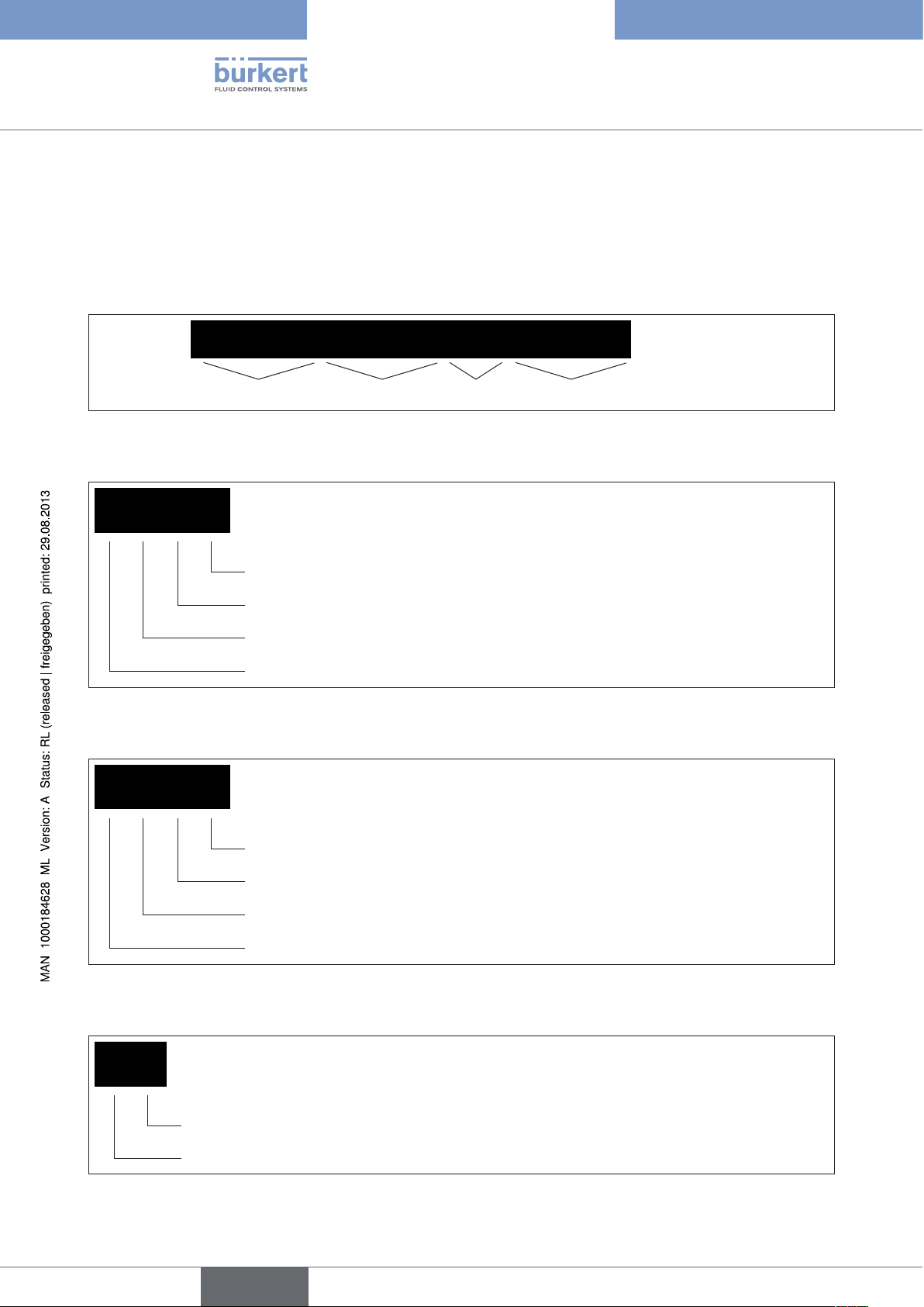
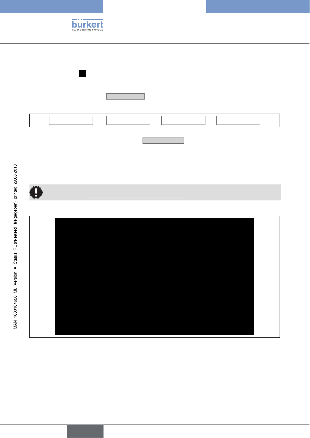
4.2.1. Toolbar
The toolbar is a combination of frequently required commands from the menu bar and project view. It is divided
into 4 sections.
Section 1 2 3 4
Figure 3: PACTware toolbar
Section 1: Icons for project administration
Print the current project
Save the current project
Open an existing project
Create a new project
Figure 4: PACTware toolbar - Section 1
Section 2: Icons for working with DTMs
Write current data to file
Write all data to the device
Read all data from the device
Edit current data
Figure 5: PACTware toolbar - Section 2
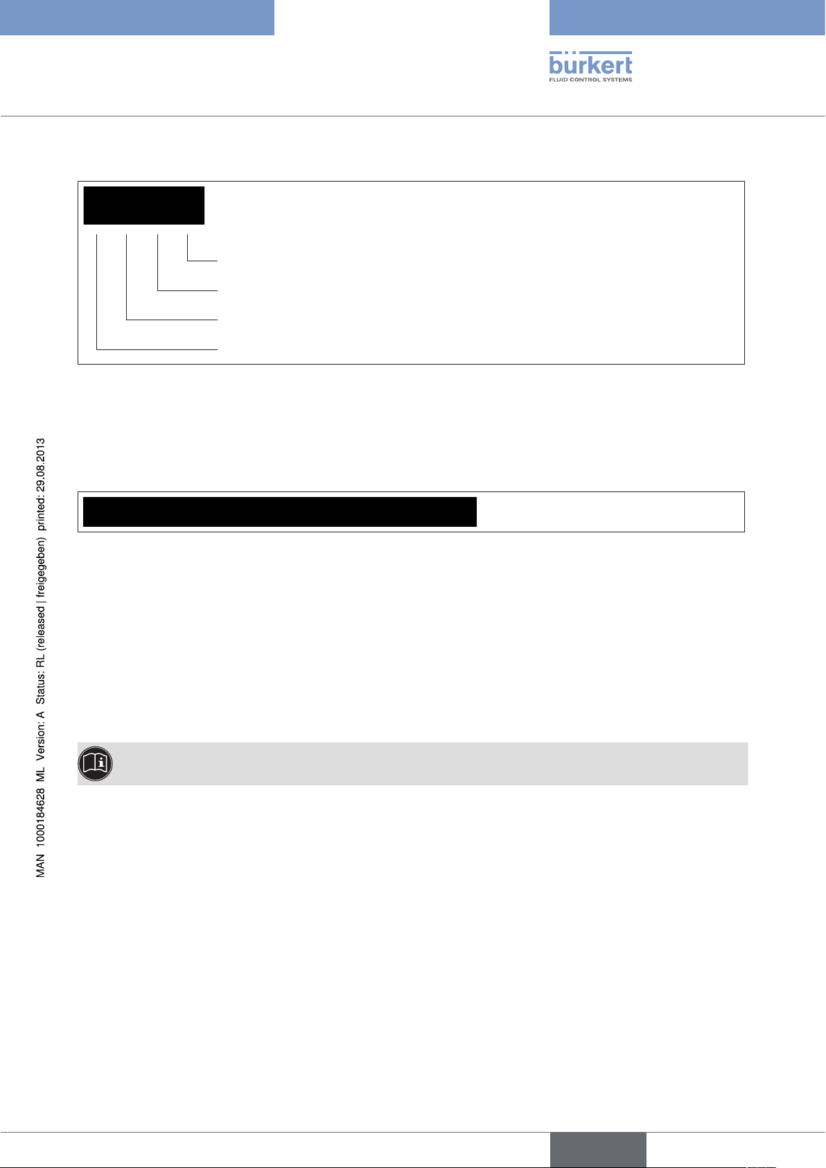
Section 3: Icons for activating specific PACTware windows
10
Device catalog
Project view
Figure 6: PACTware toolbar - Section 3
English
Page 11
Software Tool - 8x92 / 8x93
Control and display elements
Section 4: Icons for working with DTMs
Break the connection
Create a connection between the selected DTM and the field device
Delete the selected DTM from the project
Insert an additional DTM into the project at the selected position
Figure 7: PACTware toolbar - Section 4
4.2.2. Status bar
The status bar contains information about the current state of the project being processed.
Figure 8: Status bar
Meaning of the displays (from left to right):
• Connection status: Broken / connected
• Project has been changed (indicated by an asterisk)
• There are error messages. The icon flashes if the messages have not been displayed on the error monitor yet. A
Tooltip indicates the number of error messages present.
• Name of the project
• Active user role
More extensive explanations describing operation and how to create a project are available in the PACTware online help.
English
11
Page 12
Software Tool - 8x92 / 8x93
Control and display elements
4.3. Control and display elements of Bürkert DTMs
4.3.1. Toolbar
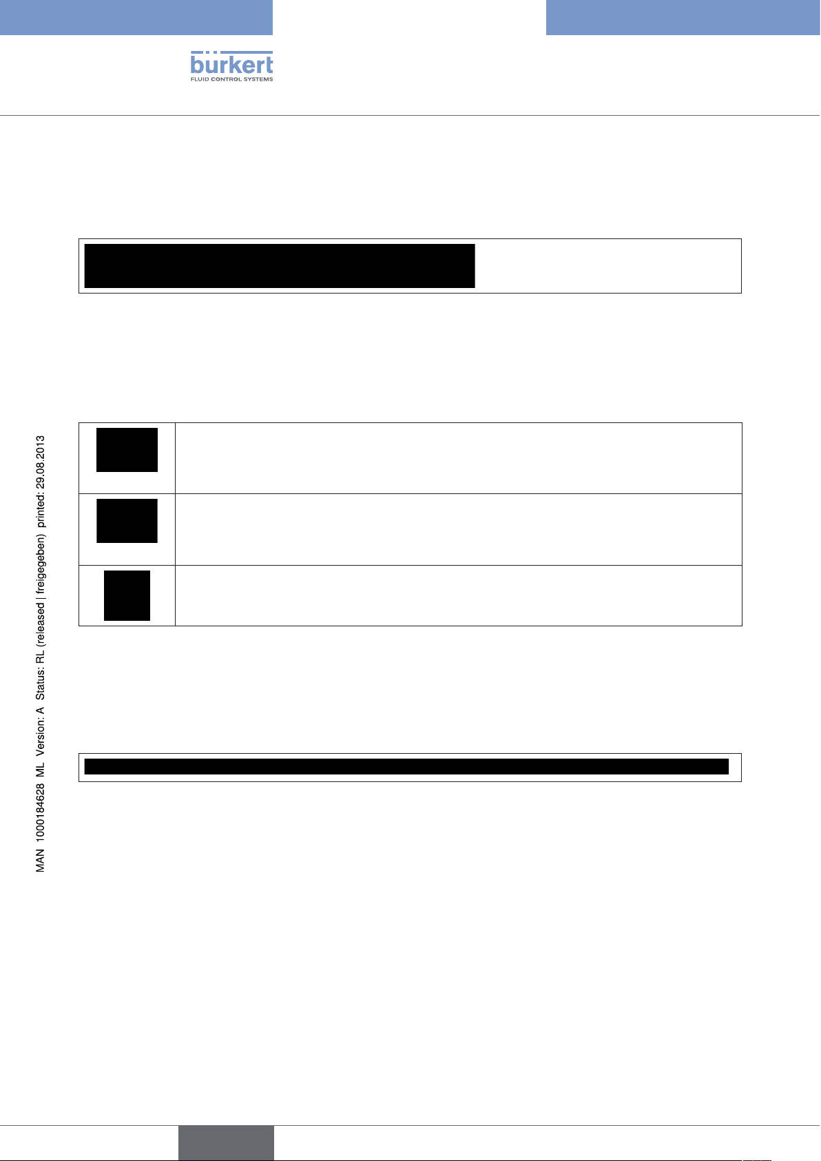
Figure 9: DTM toolbar
The section on the left contains icons for the screen display:
Show and hide identification range
Show and hide navigation range
The second section is a combination of icons for device communication:
Read parameters from device
You can select here between: Read all parameters from the device
Read directory only
Read directory and subdirectories only
Write parameters to device
You can select here between: Write all parameters to device
Write directory only
Write directory and subdirectories only
Cyclic update of parameters in display (every 2 seconds)
Table 1: DTM icons
The two sections on the right contain the help function and the print function .
4.3.2. Status bar
The status bar contains information about the current state of the project being processed.
Figure 10: Status bar
Meaning of the displays (from left to right):
• Connection status: Broken / connected
• Communication status
• Data source: Database / device
• Instance data record
• Device status
• Direct mode
• Device diagnostics
• User status
12
• Progress bar
English
Page 13
Software Tool - 8x92 / 8x93
Control and display elements
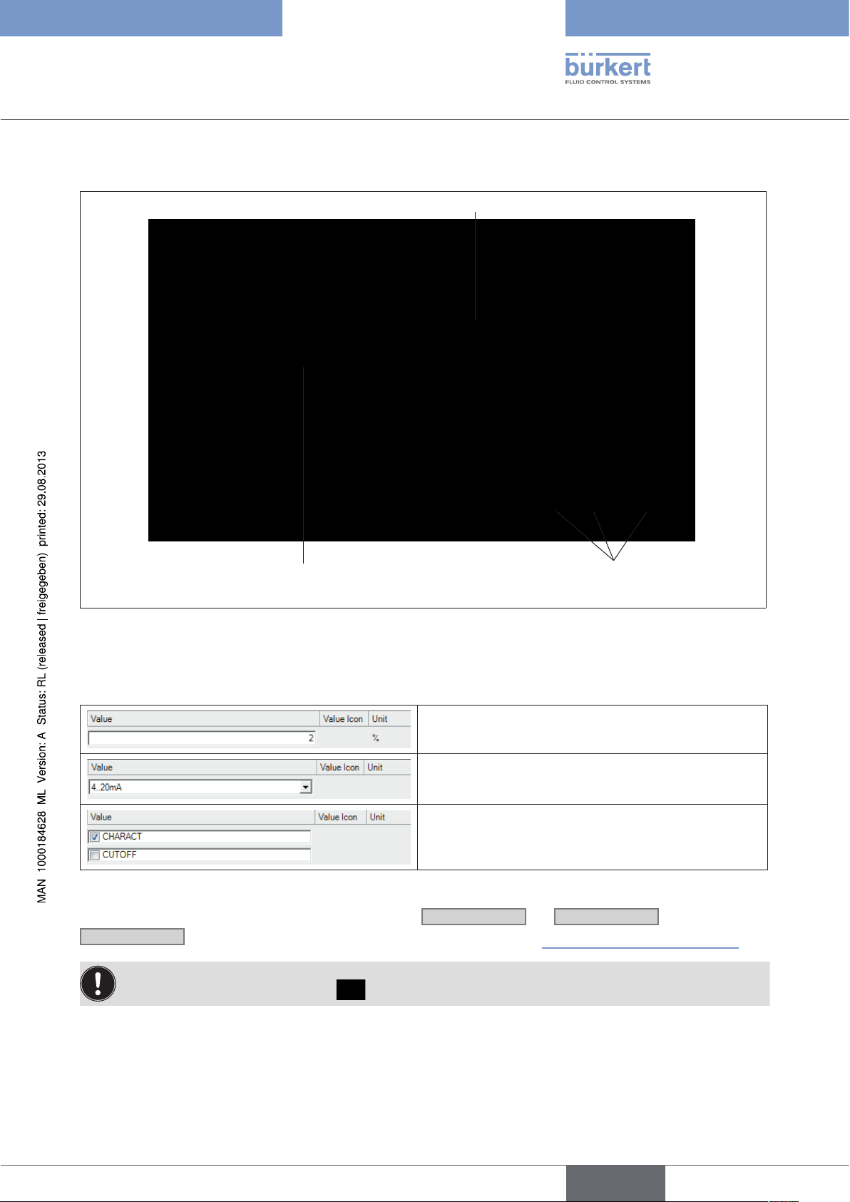
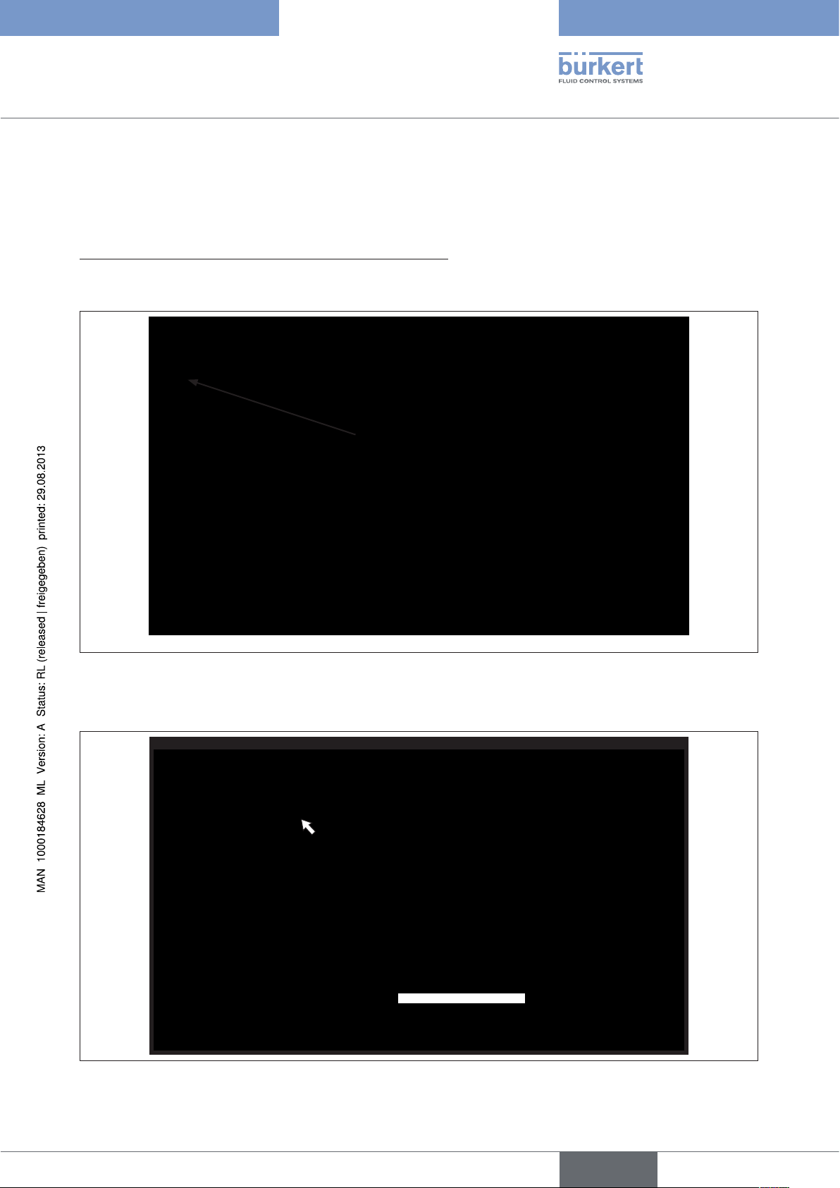
4.3.3. Navigation area and work area
Value entry in the work area
Selection of function
in the navigation area
Figure 11: Bürkert DTM screen display
Buttons for
data transfer
Functions are displayed in the navigation area.
When you click on the required function, it is highlighted in color and the corresponding (entry) screen appears:
Entry field for texts or values
Input via dropdown list
Select via checkbox
Table 2: Input screens
Parameters can be transferred to the database with the
Cancel
closes the DTM window without saving (see also Section “4.3.4. Buttons for data transfer”).
Apply
or
OK
buttons.
You can save the project with the "File / Save" menu item.
To transfer to the device, select the
icon.
English
13
Page 14
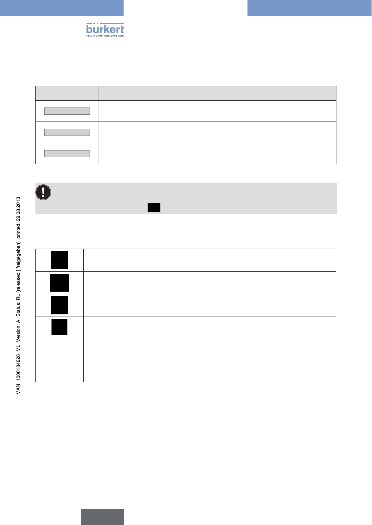
4.3.4. Buttons for data transfer
Button Description
Software Tool - 8x92 / 8x93
Control and display elements
OK
Cancel
Apply
Table 3: Buttons for data transfer
The DTM window closes
Modified values are transferred to the database.
The DTM window closes
Modified values are not transferred to the database.
The DTM window remains open
Modified values are transferred to the database.
If you exit the program without saving the project, the data in the database is not saved.
You can save the project with the "File / Save" menu item.
To transfer to the device, select the
icon.
4.3.5. Icons
Modified value not saved or not written to device
Saved to database
14
Device data
• Invalid input value
• Configuration error with communication
One or more parameters with different value ranges in the device and DTM
• Validation error with communication error
Wrong device connected (wrong manufacturer, type or device version)
Device not in communication mode (for example device in input mode)
Communication error
Table 4: Icons
English
Page 15

Software Tool - 8x92 / 8x93
Installation
5. INSTALLATION
5.1. System requirements
Hardware:
Processor: Intel Pentium/ AMD, at least 500 MHz
Working memory: At least 128 MB RAM
Hard disk: At least 250 MB free storage space
Graphics resolution: At least 1024 x 768
1 USB port to connect the Adapter USB-RS232, ID number 227093
Software:
Operating system Windows 2000/XP/Vista:
PACTware 3.6 + Microsoft .NET Framework 1.1 + .NET Framework 1.1 SP1
Operating system Windows XP/Vista/7:
PACTware 4.1 + Microsoft .NET Framework 2.0
Administrator rights are required for installation.
Windows must be rebooted after the installation. Then you must log into Windows under the same name,
because the installation is completed during the reboot.
English
15
Page 16
Software Tool - 8x92 / 8x93
Installation
5.2. Installing PACTware and DTMs
Select the appropriate PACTware version depending on the operating system in use, see chapter “5.1. System
requirements”.
All installation programs are available on the Bürkert homepage and on CD.
Before the installation, exit all programs that are open.
5.2.1. PACTware version 3.6 and .NET Framework 1.1 including
SP1
Installation of PACTware requires the presence of software platform:
Microsoft .NET Framework 1.1 with Service Pack 1 (SP1)
Procedure to follow if "Microsoft .NET Framework 1.1 with Service Pack 1 (SP1)" is not present yet on the target
computer:
→ Download and / or open the Zip file (1000103878), which includes the Microsoft.NET 1.1 framework.
→ Start "Dotnetfx.exe".
→ Download and / or open the Zip file (1000103880), which includes the Microsoft.NET 1.1 SP1 framework.
→ Start "NDP1.1sp1*.exe".
Procedure PACTware Setup:
→ Download and / or open the Zip file (1000103690), which includes the PACTware setup and unzip in a tem-
porary directory.
→ Start “Setup.exe”.
Setup file "PACTware36setup.zip" contains
• the basic setup for PACTware 3.6 with online help in various languages
16
• the HART communication DTM for PACTware 3.6
• the Generic HART DTM (not required)
After you have selected the installation language, the installation is performed.
At this point the HART communications DTM can also be installed. It is required because communication with
Bürkert devices runs via the HART protocol and the physical layer has an RS232 interface rather than a HART
interface.
English
Page 17
Software Tool - 8x92 / 8x93
Installation
Optional components such as the manual are not installed here.
If PACTware 2.4, PACTware 3.0 or PACTware 3.5 are already installed, all passwords can be transferred for
PACTware 3.6 at the end of the installation.
During the installation, a program group is entered in the Windows start menu for the current user and a link to
PACTware 3.6 appears on the desktop.
5.2.2. PACTware version 4.1 and .NET Framework 2.0
Download and / or open the Zip file “PACTware 4.1 SP1 Buerkert.zip“ and unzip in a temporary directory. This zip
file contains all the necessary installation components.
Installation of PACTware requires the presence of software platform:
Microsoft .NET Framework 2.0
Procedure to follow if “Microsoft .NET Framework 2.0“ is not present yet on the target computer:
→ Start setup
with a 64-bit operating system in directory dotNet\dotNET_20\x64
or with other operating systems in directory \dotNet\dotNET_20\x86.
Procedure PACTware Setup:
→ Start \PACTware\PACTware.msi.
Setup file contains:
• the basic setup for PACTware 4.1 with online help in various languages
• the HART communication DTM for PACTware 4.1
• the Generic HART DTM (not required)
After you have selected the installation language, the installation is performed.
At this point the HART communications DTM can also be installed. It is required because communication with
Bürkert devices runs via the HART protocol and the physical layer has an RS232 interface rather than a HART
interface.
Optional components such as the manual are not installed here.
If PACTware 2.4, PACTware 3.0, PACTware 3.5 or PACTware 3.6 are already installed, all passwords can be
transferred for PACTware 4.1 at the end of the installation.
During the installation, a program group is entered in the Windows start menu for the current user and a link to
PACTware 4.1 appears on the desktop.
English
17
Page 18

5.2.3. Bürkert device DTM
Procedure:
→ Start "Setup.exe" in the directory
AdditionalSetups\BuerkertDTMs\SETUP_Positioner_Typen_869X_879X_V1.0.0.
or alternative
→ Start “Setup.exe” in the master directory:
After you have selected the language,
Software Tool - 8x92 / 8x93
Installation
you can choose which components should be installed:
select PACTware 4.1 SP1 and Buerkert DTM Positioner 3-wire.
18
After you have selected the installation language, the installation is performed.
English
Page 19
Software Tool - 8x92 / 8x93
Operation and function
6. OPERATION AND FUNCTION
6.1. Starting PACTware
→ Start PACTware from the Windows start menu.
6.2. Creating a project
6.2.1. General description
AS a precondition for operating field devices, the device network must be represented in a PACTware project.
PACTware provides an area for this purpose where all installed DTMs are shown: The Device Catalog. Normally
the DTMs have the same name as the devices to facilitate control.
PACTware also provides a second area where the device network is represented: The Project Window. The
actual device network is represented in this project window by inserting DTMs from the device catalog. The
"HOST-PC" entry serves as the starting point for inserting a DTM. The required DTMs can be transferred from the
device catalog into the project window by double clicking or using drag and drop.
If you do not want the project window or device catalog to be visible, they can be activated in the menu
bar under "View".
If the Bürkert device DTMs are not visible in the device catalog, the device catalog must first be updated.
To update the device catalog:
→ Switch to the "Device catalog" window with "View / Device catalog" (F3)
→ Click
→ Confirm the question "Create new PACTware device catalog?" with
Update device catalog
Yes
→ After the device catalog is opened again, the Bürkert device DTMs are present; see “Figure 12: Device
catalog with HART Comm DTM and Bürkert device DTMs”
English
19
Page 20
Project window PACTware windowDevice catalog
Software Tool - 8x92 / 8x93
Operation and function
Figure 12: Device catalog with HART Comm DTM and Bürkert device DTMs
20
English
Page 21
Software Tool - 8x92 / 8x93
Operation and function
6.2.2. Creating a project for Bürkert positioners
To be able to communicate with positioners and process controllers of types 8692, 8693, 8792 and 8793, first
select HART communication DTM and then a Bürkert device DTM:
1. To select a HART communication DTM and set parameter:
→ Select "HART Communication, Fa. Codewrights GmbH" from the device catalog and double click or drag and
drop to integrate it into the project.
Figure 13: To integrate a HART communication DTM:
→ Settings for the following parameters (mark communication DTM, then select the "Device / Parameter" menu
item with the menu bar or double click on the integrated communication DTM (COM1...n)):
Buerkert Werke GmbH
Figure 14: HART communication DTM - set parameters
21
English
Page 22
Communication interface: Extended HART modem
Software Tool - 8x92 / 8x93
Operation and function
Serial interface: Port: COM1…n, depending on the connection
1)
Baudrate: 9600
Parity: None
The remaining parameters can retain their default settings.
22
Figure 15: Settings of the HART communications DTM
→ Click
OK
to transfer the set parameters to the database.
You can save the project with the "File / Save" menu item.
1) Depending on the device setting, factory setting: 9600 Bd
English
Page 23
Software Tool - 8x92 / 8x93
Operation and function
2. To select a Bürkert DTM:
Select "8692 Positioner TopControl" or "8693 Process controller TopControl" or "8792 Positioner SideControl"
or “8793 Process controller SideControl”from the device catalog and double click or drag and drop to integrate it
into the project.
Figure 16: Integrating a device
The project is now created and can be saved under "File / Save".
You can determine under PACTware "Tools / Options," in the "Project" area whether the last project
should be opened when the program starts (see “Figure 17: PACTware options”).
Figure 17: PACTware options
23
English
Page 24
Software Tool - 8x92 / 8x93
Operation and function
6.3. Basic settings
The basic settings of the positioner / process controller are implemented at the factory.
Once the device DTMs are activated, the basic settings can be adapted user-specifically:
• Define the device identification
• Run the automatic adjustment X.TUNE
• Transfer parameters (see chapter “6.4. Transferring parameters”)
• Parameterization of functions (see chapter “6.5. Parameterization”).
6.3.1. Activation of device DTMs
The DTM window is used for device identification, defining the basic settings, and parameterization of the device.
The window can be activated as follows:
• Double click on the required DTM in the project window or
• Right click and select "Parameters" or
• With the PACTware "Device / Parameters" menu item.
DTM window
Identification area
24
Figure 18: DTM window
English
Navigation area
Work area
Page 25
Software Tool - 8x92 / 8x93
Operation and function
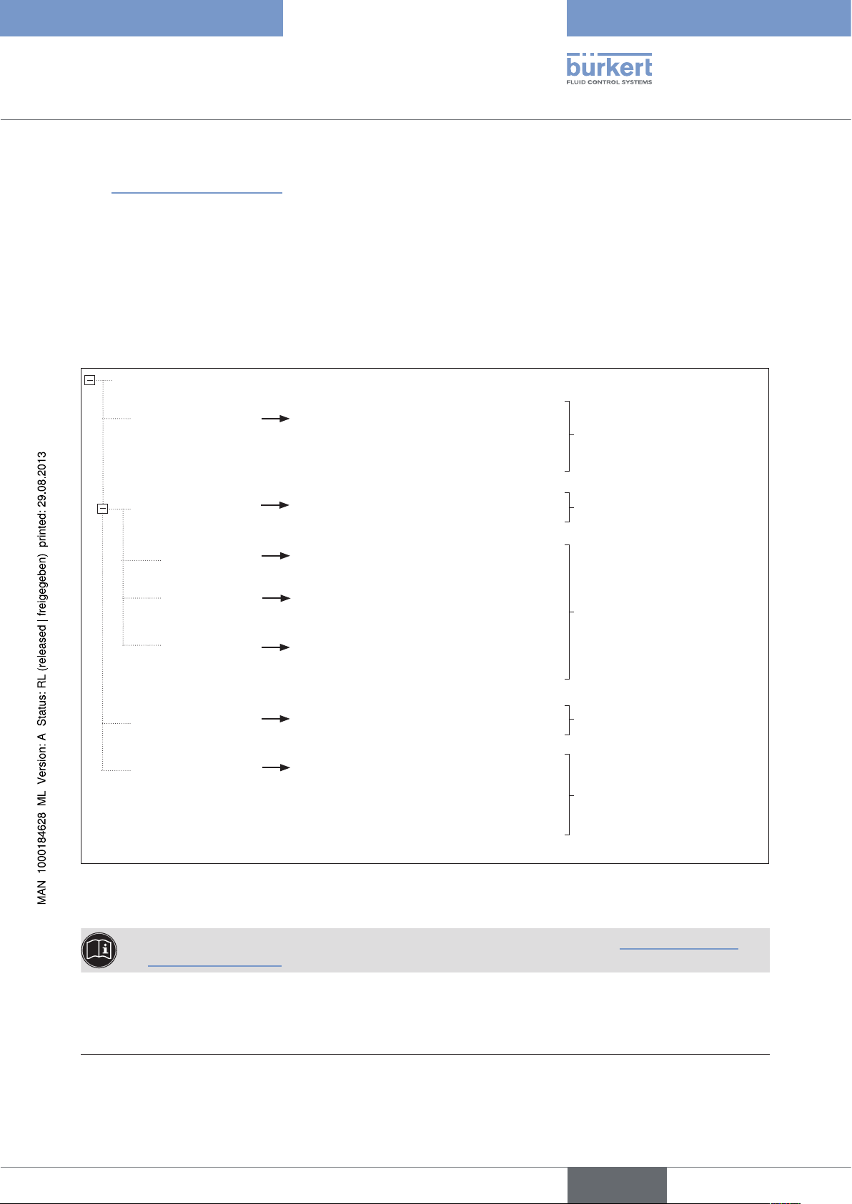
The navigation area contains the parameters and functions of the selected device in the folder structure
(see “Figure 19: Navigation area”):
Identification: Enter user-specific device designations
Device menu: Parameterization of functions
Adding auxiliary functions
RESET: Reset to factory settings
TUNE FUNCTIONS: Automatic adjustment of the positioner / process controller to the relevant operating
conditions
Parameter
Identification
Device menu
ACTUATOR
2)
INPUT
BUS.COMM
RESET
TUNE FUNCTIONS
Description
Device indicator (TAG)
Date
Device menu configure
Operating mode actuator
Set-point value input
Bus type - only readable
RESET
Start X.TUNE
Start PQ.LIN
Start P.TUNE
3)
3)
Enter user-specific device
designations
Adding auxiliary
functions
Device menu items for
parameterization of
functions
Reset to factory settings
Automatic adjustment of the
positioner / process controller to the relevant operating conditions
Figure 19: Navigation area
You can find a description and parameterization of individual functions in Sections “7. Basic functions”
and “8. Auxiliary functions”.
2) only for TopControl: Type 8692 and Type 8693
3) only for process controller Type 8693 and 8793
English
25
Page 26
Software Tool - 8x92 / 8x93
Operation and function
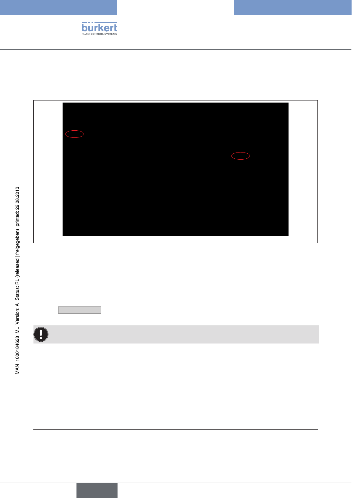
6.3.2. Device identification
User-specific device data can be entered in the navigation area under the "Identification" item.
Figure 20: Identification
Description: User-specific device description
4)
Tag: User-specific device indicator (TAG)
Date: User-specific date
→ Click
Apply
to transfer the modified parameters to the database.
You can save the project with the "File / Save" menu item.
4)
26
4) As per HART specification
English
Page 27
Software Tool - 8x92 / 8x93
Operation and function
6.3.3. Running the automatic adjustment for TUNE FUNCTIONS
X.TUNE Automatic adjustment of the positioner
5)
PQ-LIN
P.TUNE
While the TUNE FUNCTIONS is running, the valve automatically moves from its current position!
• Never run TUNE FUNCTIONS while a process is running!
• Take appropriate measures to prevent the system / positioner / process controller from being unintentionally
actuated!
Automatic linearization of the process characteristic
5)
Self-optimization of the process controller
The TUNE FUNCTIONS must be run for a function check of the positioner / process controller to adjust
to specific local features.
WARNING!
NOTE!
Avoid maladjustment of the controller due to an incorrect compressed air supply or applied operating
medium pressure!
• Run TUNE FUNCTIONS whenever the compressed air supply (= pneumatic auxiliary energy) is available
during subsequent operation.
• Run the TUNE FUNCTIONS function preferably without operating medium pressure to exclude interference
caused by flow forces.
Set up connection
Figure 21: Starting TUNE FUNCTIONS
5) only with process controller Type 8693 and 8793
27
English
Page 28
Procedure example: function X.TUNE:
→ Set up connection
→ Set up TUNE FUNCTIONS in the navigation area
Software Tool - 8x92 / 8x93
Operation and function
→ Start X.TUNE. To do this, click
Start X.TUNE
6).
The progress of X.TUNE is shown in the communication software:
XTUNE start POS 100 ... XTUNE end
Automatic adjustment can be interrupted with the
When the automatic adjustment completes, the message "XTUNE end" appears
► ► ►
Break X.TUNE
button.
7)
.
The changes are automatically transferred to the positioner's / process controller’s memory (EEPROM) after the
X.TUNE function is successful.
After X.TUNE is complete, read the device parameter for processing from the positioner / process controller (see chapter “6.4.1. Reading parameters from the device”).
28
Figure 22: X.TUNE (example Type 8693)
6) X.TUNE can also be started on the positioner / process controller (see the relevant device operating
instructions).
7) If an error occurs, an error message appears (see Chapter “6.6. Error messages”).
English
Page 29
Software Tool - 8x92 / 8x93
Operation and function
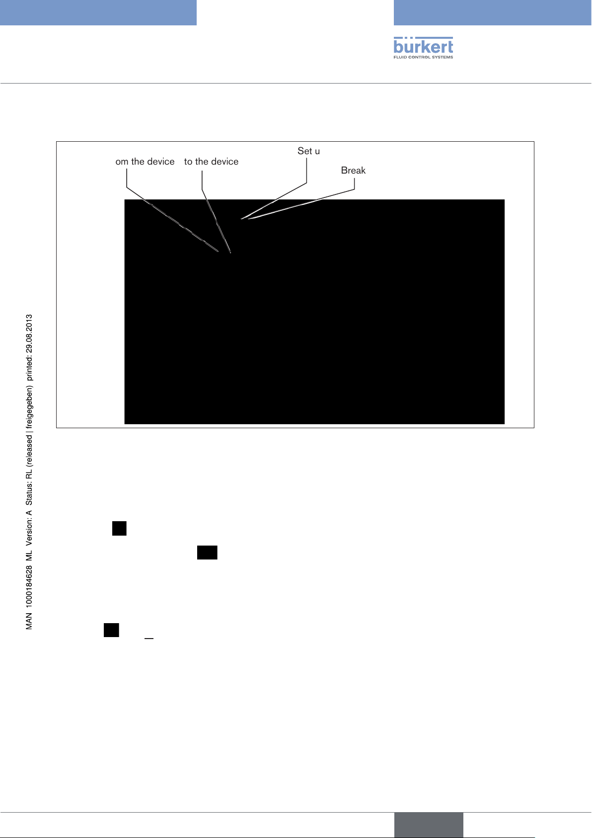
6.4. Transferring parameters
DTM: Read parameters from the device
Figure 23: Transferring parameters
DTM: Write parameters
to the device
Set up connection
Break connection
6.4.1. Reading parameters from the device
Procedure:
→ Connect
→ Read parameters from device
with option to select: Read all parameters from device
Read directory only
Read directory and subdirectories only
If the parameters are transferred using the PACTware "Device / Load from device" menu item or using the
PACTware
icon, all parameters are read from the device.
29
English
Page 30
Software Tool - 8x92 / 8x93
Operation and function
6.4.2. Write parameters to the device
NOTE!
If changes are made and transferred with the "Write all parameters to device" function, it is possible that
parameters in the device will be unintentionally overwritten!
• Read the current device data before you make the changes or
• transfer only the modified parameters by using the selection options "Write directory only" or "Write directory
and subdirectories only".
Procedure:
→ Connect
→ Write parameters to device
with option to select: Write all parameters to device
Write directory only
Write directory and subdirectories only
If the parameters are transferred using the PACTware "Device / Store to device" menu item or using the
PACTware
icon, all (!) parameters will be written to the device.
More extensive explanations describing operation and how to create a project are available in the PACTware
online help. For start-up and parameterization, refer also to the operating instructions for the relevant device.
6.5. Parameterization
A distinction is made in parameterization between offline and online mode.
Offline mode
In Offline mode the project can be created and parameters can be changed and saved without devices connected. Then the data can be saved later to connected devices in Online mode
Online mode
In Online mode the device to be parameterized must be connected and ready for operation. Selecting the corresponding DTM by right clicking and selecting the "Connect" command or with PACTware menu "Device /
Connect" causes Online mode to be prepared. Then parameters can be read directly from the device or trans-
8)
ferred to the device
.
8)
.
30
8) Note regarding read / write device data:
The device DTM is a universally valid DTM containing all parameters for all device variants. A check therefore
determines before the data transfer from DTM which device variant is connected and deactivates the
parameters/ menu items of variants not present in the DTM.
English
Page 31

Software Tool - 8x92 / 8x93
Operation and function
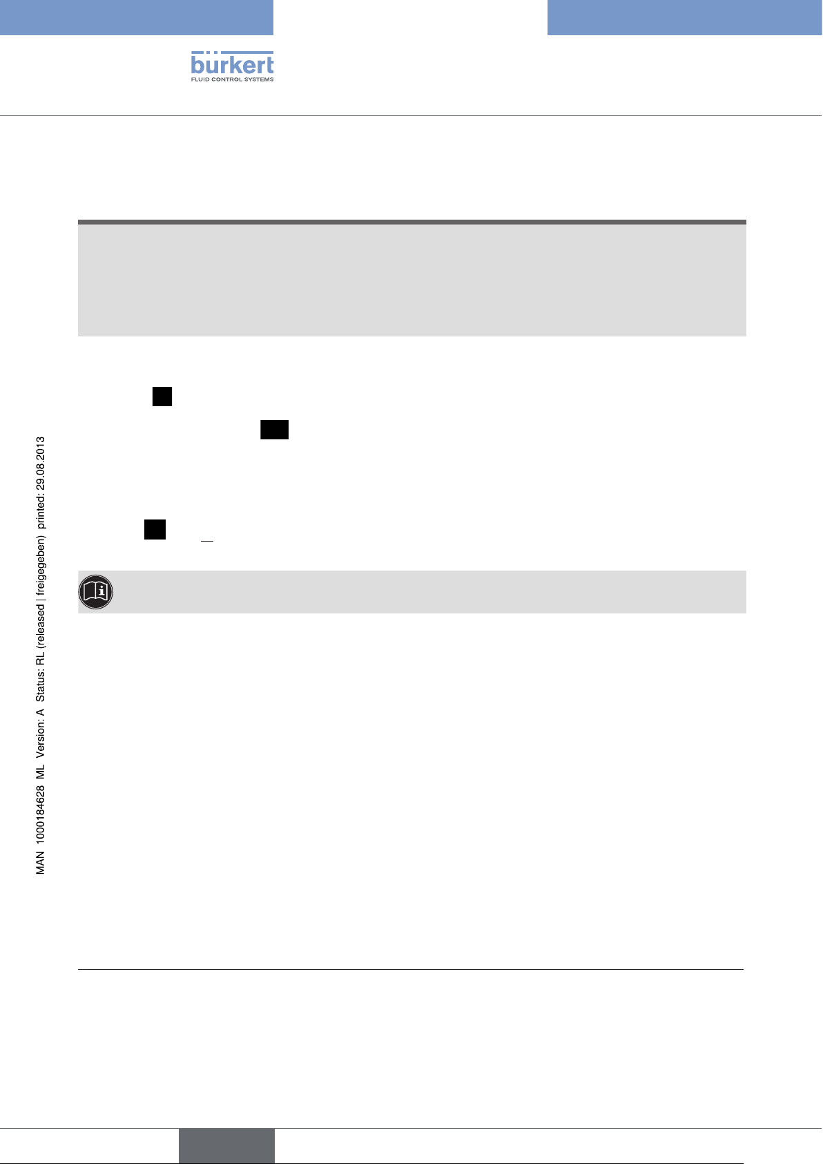
6.5.1. Parameterizing functions
Value entry in the work area
Selection of function
in the navigation area
Figure 24: Parameterizing functions
Procedure:
Buttons
→ Select the function in the navigation area (highlighted in color)
→ Select or enter the values in the work area
→ Modified values can be transferred to the database with the
you exit the function with the
You can save the project with the "File / Save" menu item.
All setting that are made must still be transferred to the device (see chapter “6.4. Transferring parameters”).
Cancel
button, the changes are not transferred.
Apply
or
OK
button. If
English
31
Page 32

Software Tool - 8x92 / 8x93
Operation and function
6.6. Error messages
6.6.1. Error messages while the X.TUNE function is running
Display Cause of fault Remedial action
ERR 1:
No pilot air
ERR 2:
Pilot air failed during
X.TUNE
ERR 3:
Control system
deaeration side leaking
ERR 4:
Control system aeration
side leaking
Table 5: Error messages for X.TUNE
No pilot air connected Connect pilot air
Pilot air failure while the X.TUNE function was
running
Actuator or control system deaeration side
leaking
Control system aeration side leaking Not possible, device defective
Check pilot air supply
Not possible, device defective
6.6.2. Error messages while the PQ.LIN function is running
Display Cause of fault Remedial action
ERR 1:
No pilot air or no
change to process
variable
No compressed air connected
No change to process variable
Connect compressed air
Check process and, if required,
switch on pump or open the shutoff valve.
32
ERR 2:
Current node (valve
stroke) was not reached
Table 6: Error messages for PQ.LIN
Current node of the valve stroke was not
reached, as
• Pilot air failed during P.Q’LIN
• X.TUNE was not run.
English
Check pilot air
Run X.TUNE
Check process sensor
Page 33

Software Tool - 8x92 / 8x93
Operation and function
6.6.3. Error messages while the P.TUNE function is running
Display Cause of fault Remedial action
ERR 1:
No pilot air or no
change to process
No pilot air connected
No change to process variable
variable
Table 7: Error messages for P.TUNE
Connect pilot air
Check process and, if required,
switch on pump or open the shutoff valve.
Check process sensor
English
33
Page 34

Software Tool - 8x92 / 8x93
Basic functions
7. BASIC FUNCTIONS
7.1. Overview of basic functions
The following basic functions are created as device menu items in the navigation area in the factory:
ACTUATOR
INPUT
BUS.COMM
RESET
TUNE FUNCTIONS
9)
Inputting the operating mode of the pneumatic actuator
Entry of the standard signal for the set-point value
Adjust the selection / parameters of the field bus interface
Reset to factory settings
Automatic adjustment of the positioner / process controller to the relevant operating
conditions
Table 8: Basic functions
7.2. Basic functions - parameter
Parameterization and transfer of parameters are described in sections “6.5. Parameterization” and “6.4.
Transferring parameters”.
NOTE!
If changes are made and transferred with the "Write all parameters to device" function, it is possible that
parameters in the device will be unintentionally overwritten!
34
• Read the current device data before you make the changes or
• transfer only the modified parameters by using the selection options "Write directory only" or "Write directory
and subdirectories only".
Modified values can be transferred to the database with the
button. If you exit the function with the
Cancel
button, the changes are not transferred.
Apply
or
OK
You can save the project with the "File / Save" menu item.
9) Only for Types 8692 / 8693
English
Page 35

Software Tool - 8x92 / 8x93
Basic functions
7.3. Basic functions - setting parameter
7.3.1. ACTUATOR -
Inputting the operating mode of the pneumatic actuator
Only for Types 8692 / 8693.
The operating mode of the pneumatic valve actuator used in combination with the positioner / process controller
can be input in this menu option.
The operating mode of the actuator has been preset at the factory.
CFA and CFB: single-acting
CFI: double-acting
The control function (CF) of the actuator can be found on the type label.
ACTUATOR
Figure 25: ACTUATOR function
Operating mode actuator
7.3.2. INPUT -
Enter the standard signal
Under this menu option, enter the standard signal used for the set-point value.
→
Factory setting: 4 – 20 mA
INPUT
setpoint input
single-acting
single-acting
double-acting
4 ... 20 mA
4 ... 20 mA
0 ... 20 mA
0 ... 10 V
0 ... 5 V
Figure 26: INPUT function
35
English
Page 36

7.3.3. BUS.COMM -
Adjust the selection / parameters of the field bus interface
Select the field bus interface for the positioner / process controller.
→
Factory setting: without bus
BUS.COMM
Figure 27: BUS.COMM function
When you select a field bus, the corresponding bus parameters can be adjusted.
Bus type - only readable
without bus
without bus
Profibus DP-V1
DeviceNet
Software Tool - 8x92 / 8x93
Basic functions
7.3.4. RESET -
Reset to factory settings
This function can be used to reset the positioner to the factory settings.
RESET
Figure 28: DIR.CMD function
Procedure:
RESET
→ Connect
→ Click
The parameters of the serial interface are set to the following default values:
9600 Bd, parity NONE and 1 stop bit.
Execute
.
→ If there is a deviation from the settings in the communication DTM, the parameters of the serial
interface are readjusted (either on the device side or PC side with the HART communication DTM, see
chapter “6.2.2. Creating a project for Bürkert positioners”).
Execute
36
7.3.5. TUNE FUNCTIONS -
Automatic adjustment of the positioner / process controller
to the relevant operating conditions
A description of the TUNE FUNCTIONS may be found in Section “6.3.3. Running the automatic
adjustment for TUNE FUNCTIONS”.
English
Page 37

Software Tool - 8x92 / 8x93
Auxiliary functions
8. AUXILIARY FUNCTIONS
8.1. Overview of auxiliary functions
The following auxiliary functions can be added to the device menu:
CHARACT
Selection of the transfer characteristic between input signal and stroke (correction
characteristic)
CUTOFF
DIR.CMD
DIR.ACTUATOR
SPLITRANGE
Sealing function for position controller
Effective sense of direction between input signal and nominal position
Assignment of the aeration state of the actuator chamber to the actual position
Signal split range; input signal as % for which the valve runs through the entire stroke
range.
X.LIMIT
X.TIME
X.CONTROL
P.CONTROL
10)
SECURITY
SAFE POSITION
SIGNAL ERROR
BINARY INPUT
OUTPUT
CAL.USER
SET FACTORY
Limit the mechanical stroke range
Limit the control speed
Parameterize the positioner
Parameterize the process controller
Code protection for settings
Definition of the safety position
Configuration of signal level fault detection
Activation of the binary input
Configuration of the output (option)
Calibration (only a device menu item can be activated)
Reset to factory settings (only a device menu item can be activated, run RESET: see
chapter “7.1. Overview of basic functions”)
SERIAL IO
EXTRAS
POS.SENSOR
SERVICE
SIMULATION
DIAGNOSE
Table 9: Auxiliary functions
Configuration of serial interface
Configuration of display
11)
Setting interface for remote sensor
For internal use only
Simulation (only a device menu item can be activated)
Diagnostic menu (option)
10) Only available for process controller Type 8693 and 8793
11) Only available for process controller Type 8793 - only possible for Type 8793 Remote
English
37
Page 38

Software Tool - 8x92 / 8x93
Auxiliary functions
8.2. Adding auxiliary functions (ADD.FUNCTION)
Procedure:
→ When you select the "Device Menu" function in the navigation area (highlighted in color), the auxiliary func-
tions appear in the work area.
→ Activate the auxiliary functions you need in the checkboxes. They will be added to the folder structure in the
navigation area immediately
Parameterization is performed in the relevant function.
38
Figure 29: Configuring auxiliary functions
8.3. Removing auxiliary functions (ADD.FUNCTION)
Procedure:
→ When you select the "Device Menu" function in the navigation area (highlighted in color), the auxiliary func-
tions appear in the work area.
→ Deactivate the auxiliary functions you do not need in the checkboxes. They will be removed from the folder
structure in the navigation area immediately.
English
Page 39

Software Tool - 8x92 / 8x93
Auxiliary functions
8.4. Auxiliary functions - parameter
Parameterization and transfer of parameters are described in Sections “6.5. Parameterization” and “6.4.
Transferring parameters”.
NOTE!
If changes are made and transferred with the "Write all parameters to device" function, it is possible that
parameters in the device will be unintentionally overwritten!
• Read the current device data before you make the changes or
• transfer only the modified parameters by using the selection options "Write directory only" or "Write directory
and subdirectories only".
Modified values can be transferred to the database with the
button. If you exit the function with the
You can save the project with the "File / Save" menu item.
Cancel
button, the changes are not transferred.
Apply
or
8.5. Auxiliary functions - setting parameter
The additional functions are described in detail in the relevant operating instructions of the positioner /
process controller.
OK
English
39
Page 40

Software Tool - 8x92 / 8x93
Deinstallation of PACTware/ DTMs
9. DEINSTALLATION OF PACTWARE/ DTMS
9.1. Deinstallation process
Procedure:
→ Select the "Software" item in the system control (via "Start / Settings / System Control").
→ Select "HART Communication DTM" or "Buerkert Positioner DTM" from the "PACTware" list and click "Change /
remove".
→ Run the deinstallation as suggested by the wizard and complete the process by rebooting Windows.
40
English
Page 41

Software Tool - 8x92 / 8x93
Kommunikationssoftware (Software Tool) für Positioner / Prozessregler
Inhalt
1. ERGÄNZENDE BEDIENUNGSANLEITUNG .........................................................................................................................44
1.1. Darstellungsmittel ..............................................................................................................................................................44
2. ALLGEMEINE HINWEISE ..............................................................................................................................................................45
2.1. Kontaktadressen .................................................................................................................................................................45
2.2. Informationen im Internet ...............................................................................................................................................45
3. PRODUKTBESCHREIBUNG ........................................................................................................................................................46
3.1. Erforderliche Komponenten ..........................................................................................................................................46
3.1.1. Windows 2000, XP, Vista .....................................................................................................................46
3.1.2. Windows XP, Vista, 7 .............................................................................................................................46
3.2. Begriffsdefinitionen PACTware / FDT / DTM .......................................................................................................46
4. BEDIEN- UND ANZEIGEELEMENTE .......................................................................................................................................47
4.1. Übersicht Bildschirmanzeige .......................................................................................................................................47
4.2. Bedien- und Anzeigeelemente PACTware ............................................................................................................48
4.2.1. Symbolleiste .............................................................................................................................................48
4.2.2. Statusleiste ...............................................................................................................................................49
4.3. Bedien- und Anzeigeelemente der Bürkert DTMs ............................................................................................50
4.3.1. Symbolleiste .............................................................................................................................................50
4.3.2. Statusleiste ...............................................................................................................................................50
4.3.3. Navigationsbereich und Arbeitsbereich ............................................................................................. 51
4.3.4. Schaltflächen zur Datenübernahme .................................................................................................... 52
4.3.5. Symbole .....................................................................................................................................................52
5. INSTALLATION ...................................................................................................................................................................................53
5.1. Systemanforderungen ......................................................................................................................................................53
5.2. PACTware und DTMs installieren ...............................................................................................................................54
5.2.1. PACTware Version 3.6 und .NET Framework 1.1 einschließlich SP1 ........................................54
5.2.2. PACTware Version 4.1 und .NET Framework 2.0 ............................................................................55
5.2.3. Bürkert Geräte DTM ...............................................................................................................................56
deutsch
41
Page 42

Software Tool - 8x92 / 8x93
6. BEDIENUNG UND FUNKTION ...................................................................................................................................................57
6.1. PACTware starten ...............................................................................................................................................................57
6.2. Projekt erstellen ..................................................................................................................................................................57
6.2.1. Allgemeine Beschreibung .....................................................................................................................57
6.2.2. Projekt für Bürkert Positioner erstellen ...............................................................................................59
6.3. Grundeinstellungen ...........................................................................................................................................................62
6.3.1. Aktivieren der Geräte DTM....................................................................................................................62
6.3.2. Geräteidentifikation .................................................................................................................................64
6.3.3. Ausführen der automatischen Anpassungen - TUNE FUNKTIONEN ..................................65
6.4. Parameter übertragen ......................................................................................................................................................67
6.4.1. Parameter aus dem Gerät lesen .......................................................................................................... 67
6.4.2. Parameter in das Gerät schreiben ......................................................................................................68
6.5. Parameter einstellen .........................................................................................................................................................68
6.5.1. Parameter einstellen bei Funktionen ...................................................................................................69
6.6. Fehlermeldungen ................................................................................................................................................................70
6.6.1. Fehlermeldungen bei der Durchführung der Funktion X.TUNE ..................................................70
6.6.2. Fehlermeldungen bei der Durchführung der Funktion PQ.LIN ...................................................70
6.6.3. Fehlermeldungen bei der Durchführung der Funktion P.TUNE ..................................................71
7. GRUNDFUNKTIONEN ........................................................................................................................................................................ 72
7.1. Übersicht Grundfunktionen ...........................................................................................................................................72
7.2. Grundfunktionen - Parameter ......................................................................................................................................72
7.3. Grundfunktionen - Parameter einstellen ................................................................................................................73
7.3.1. ACTUATOR -
Eingabe der Funktionsweise des pneumatischen Antriebs ...........................................................73
7.3.2. INPUT -
Eingabe des Normsignals .....................................................................................................................73
7.3.3. BUS .COMM -
Auswahl / Parameter einstellen der Feldbusschnittstelle ..............................................................74
42
7.3.4. RESET -
Rücksetzen auf die Werkseinstellungen ............................................................................................74
7.3.5. TUNE FUNKTIONEN -
Automatische Anpassung des Positioners / Prozessreglers an die jeweiligen Betriebsbedin-
gungen .......................................................................................................................................................74
deutsch
Page 43

Software Tool - 8x92 / 8x93
8. ZUSATZFUNKTIONEN ...................................................................................................................................................................75
8.1. Übersicht Zusatzfunktionen ..........................................................................................................................................75
8.2. Zusatzfunktionen hinzufügen (ADD.FUNCTION) ...............................................................................................76
8.3. Zusatzfunktionen entfernen (ADD.FUNCTION) ..................................................................................................76
8.4. Zusatzfunktionen - Parameter ........................................................................................................................................ 77
8.5. Zusatzfunktionen - Parameter einstellen...............................................................................................................77
9. DEINSTALLATION VON PACTWARE / DTMS.....................................................................................................................78
9.1. Deinstallationsablauf ........................................................................................................................................................78
deutsch
43
Page 44

Software Tool - 8x92 / 8x93
Ergänzende Bedienungsanleitung
1. ERGÄNZENDE BEDIENUNGSANLEITUNG
Die ergänzende Bedienungsanleitung beschreibt die Kommunikationssoftware für Positioner / Prozessregler TopControl und SideControl.
Informationen zur Sicherheit!
Sicherheitshinweise und Informationen für den Einsatz des Geräts finden Sie in der dazugehörigen
Bedienungsanleitung.
• Die Bedienungsanleitung muss gelesen und verstanden werden.
1.1. Darstellungsmittel
GEFAHR!
Warnt vor einer unmittelbaren Gefahr!
• Bei Nichtbeachtung sind Tod oder schwere Verletzungen die Folge.
WARNUNG!
Warnt vor einer möglicherweise gefährlichen Situation!
• Bei Nichtbeachtung drohen schwere Verletzungen oder Tod.
VORSICHT!
Warnt vor einer möglichen Gefährdung!
• Nichtbeachtung kann mittelschwere oder leichte Verletzungen zur Folge haben.
HINWEIS!
Warnt vor Sachschäden!
• Bei Nichtbeachtung kann das Gerät oder die Anlage beschädigt werden.
bezeichnet wichtige Zusatzinformationen, Tipps und Empfehlungen.
44
verweist auf Informationen in dieser Bedienungsanleitung oder in anderen Dokumentationen.
→ markiert einen Arbeitsschritt, den Sie ausführen müssen.
deutsch
Page 45

Software Tool - 8x92 / 8x93
Allgemeine Hinweise
2. ALLGEMEINE HINWEISE
2.1. Kontaktadressen
Deutschland
Bürkert Fluid Control Systems
Sales Center
Chr.-Bürkert-Str. 13-17
D-74653 Ingelfingen
Tel. + 49 (0) 7940 - 10 91 111
Fax + 49 (0) 7940 - 10 91 448
E-mail: info@de.buerkert.com
International
Die Kontaktadressen finden Sie im Internet unter:
www.burkert.com
2.2. Informationen im Internet
Bedienungsanleitungen und Datenblätter zu den Gerätetypen finden Sie im Internet unter:
www.buerkert.de
deutsch
45
Page 46

3. PRODUKTBESCHREIBUNG
3.1. Erforderliche Komponenten
3.1.1. Windows 2000, XP, Vista
• Microsoft .NET Framework 1.1
• Microsoft .NET Framework 1.1 Service Pack 1
• PACTware Version 3.6
einschließlich HART-Protokoll-Treiber, Fa. Codewrights GmbH
• Bürkert Geräte DTM
„8692 Positioner TopControl“
„8693 Prozessregler TopControl“
„8792 Positioner SideControl“
„8793 Prozessregler SideControl“
Software Tool - 8x92 / 8x93
Produktbeschreibung
• Firmware Version ab C.01 bei Gerätetypen 8692 und 8693 bzw. ab B.01 bei Gerätetypen 8792 und 8793
• Adapter USB-RS232, Ident-Nr. 227093 (HART Kommunikation über die 4/20 mA - Schnittstelle ist nicht möglich).
3.1.2. Windows XP, Vista, 7
• Microsoft .NET Framework 2.0
• PACTware Version 4.1
einschließlich HART-Protokoll-Treiber, Fa. Codewrights GmbH
• Bürkert Geräte DTM
„8692 Positioner TopControl“
„8693 Prozessregler TopControl“
„8792 Positioner SideControl“
„8793 Prozessregler SideControl“
• Firmware Version ab C.01 bei Gerätetypen 8692 und 8693 bzw. ab B.01 bei Gerätetypen 8792 und 8793
• Adapter USB-RS232, Ident-Nr. 227093 (HART Kommunikation über die 4/20 mA - Schnittstelle ist nicht möglich).
3.2. Begriffsdefinitionen PACTware / FDT / DTM
PACTware (Process Automation Configuration Tool):
Hersteller- und feldbusunabhängige Software zur Inbetriebnahme, Bedienung und Wartung von Feldgeräten aller
Art. In dieses Rahmenprogramm werden die DTM (Device Type Manager) der entsprechenden Feldgerätehersteller eingebunden. Die Einbindung erfolgt nach der Schnittstellenspezifikation FDT 1.20.
Zur Bedienung eines Feldgeräts ist also immer ein DTM erforderlich, der zu diesem Gerätetyp passt.
46
FDT (Field Device Tool):
Standardisierte Schnittstellenbeschreibung, definiert den Datenaustausch zwischen den verschiedenen DTMs
und der Rahmenapplikation, z. B. PACTware.
DTM (Device Type Manager):
Der DTM ist das eigentliche Bedienmodul der Aktoren, Sensoren und Feldkomponenten. Er beinhaltet alle spezifischen Daten und Funktionen eines bestimmten Gerätetyps und liefert alle Elemente und Dialoge zur Bedienung.
Ein DTM ist nur lauffähig in einem Rahmenprogramm wie z. B. PACTware.
deutsch
Page 47

Software Tool - 8x92 / 8x93
Bedien- und Anzeigeelemente
4. BEDIEN- UND ANZEIGEELEMENTE
4.1. Übersicht Bildschirmanzeige
PACTware Fenster
PACTware Symbolleiste
DTM Fenster
DTM Symbolleiste
Identifikationsbereich
Navigationsbereich
PACTware Statusleiste
Projektfenster
Bild 1: Übersicht Bildschirmanzeige
Viele Symbole und Parameter haben Tooltips (Kurzinfo), die die Funktion erläutern.
Bild 2: Tooltip
DTM Statusleiste
Arbeitsbereich
Schaltflächen
47
deutsch
Page 48

Software Tool - 8x92 / 8x93
Bedien- und Anzeigeelemente
4.2. Bedien- und Anzeigeelemente PACTware
4.2.1. Symbolleiste
Häufig benötigte Befehle aus der Menüleiste und der Projektansicht sind in einer Symbolleiste zusammengefasst.
Die Symbolleiste ist in 4 Abschnitte aufgeteilt.
Abschnitt 1 2 3 4
Bild 3: PACTware Symbolleiste
Abschnitt 1: Symbole für Projektverwaltung
Drucken des aktuellen Projekts
Speichern des aktuellen Projekts
Öffnen eines bestehenden Projekts
Anlegen eines neuen Projekts
Bild 4: PACTware Symbolleiste - Abschnitt 1
Abschnitt 2: Symbole für Arbeit mit DTMs
aktuelle Daten in Datei schreiben
alle Daten in das Gerät schreiben
alle Daten aus dem Gerät lesen
aktuelle Daten bearbeiten
Bild 5: PACTware Symbolleiste - Abschnitt 2
Abschnitt 3: Symbole für Aktivierung bestimmter PACTware Fenster
48
Gerätekatalog
Projektansicht
Bild 6: PACTware Symbolleiste - Abschnitt 3
deutsch
Page 49

Software Tool - 8x92 / 8x93
Bedien- und Anzeigeelemente
Abschnitt 4: Symbole für Arbeit mit DTMs
die Verbindung trennen
Verbindung zwischen dem selektierten DTM und dem Feldgerät herstellen
den selektierten DTM aus dem Projekt löschen
einen weiteren DTM an der selektierten Position ins Projekt einfügen
Bild 7: PACTware Symbolleiste - Abschnitt 4
4.2.2. Statusleiste
Die Statusleiste enthält Informationen über den aktuellen Zustand des bearbeiteten Projekts.
Bild 8: Statusleiste
Die Anzeigen bedeuten (von links nach rechts):
• Verbindungsstatus : getrennt / verbunden
• Projekt wurde geändert (durch Stern gekennzeichnet)
• Fehlermeldungen liegen vor. Das Symbol blinkt, wenn die Meldungen noch nicht im Fehlermonitor angezeigt
wurden. Ein Tooltip zeigt die Anzahl der anstehenden Fehlermeldungen an.
• Name des Projekts
• aktive Benutzerrolle
Weiterführende Erklärungen zur Bedienung und Projekterstellung entnehmen Sie bitte der Online-Hilfe
von PACTware.
deutsch
49
Page 50

Software Tool - 8x92 / 8x93
Bedien- und Anzeigeelemente
4.3. Bedien- und Anzeigeelemente der Bürkert DTMs
4.3.1. Symbolleiste
Bild 9: DTM Symbolleiste
Der linke Abschnitt enthält Symbole zur Bildschirmanzeige:
Identifikationsbereich ein- und ausblenden
Navigationsbereich ein- und ausblenden
Im zweiten Abschnitt sind die Symbole für die Gerätekommunikation zusammengefasst:
Parameter aus dem Gerät lesen
hier kann unterschieden werden zwischen: Alle Parameter aus dem Gerät lesen
Nur Verzeichnis lesen
Nur Verzeichnis und Unterverzeichnisse lesen
Parameter ins Gerät schreiben
hier kann unterschieden werden zwischen: Alle Parameter ins Gerät schreiben
Nur Verzeichnis schreiben
Nur Verzeichnis und Unterverzeichnisse schreiben
Zyklische Aktualisierung angezeigter Parameter (2 s)
Tabelle 1: DTM Symbole
In den beiden rechten Abschnitten befinden sich die Hilfefunktion und die Druckfunktion.
4.3.2. Statusleiste
Die Statusleiste enthält Informationen über den aktuellen Zustand des bearbeiteten Projekts.
Bild 10: Statusleiste
Die Anzeigen bedeuten (von links nach rechts):
• Verbindungsstatus: getrennt / verbunden
• Kommunikationszustand
• Datenquelle: Datenbank / Gerät
• Instanzdatensatz
• Gerätezustand
• Direktmodus
• Gerätediagnose
• Benutzerstatus
50
• Progress (Fortschrittsanzeige)
deutsch
Page 51

Software Tool - 8x92 / 8x93
Bedien- und Anzeigeelemente
4.3.3. Navigationsbereich und Arbeitsbereich
Werteeingabe im Arbeitsbereich
Auswahl der Funktion im
Navigationsbereich
Bild 11: Bildschirmanzeige Bürkert DTM
Schaltflächen zur
Datenübenahme
Die Auswahl der Funktionen erfolgt im Navigationsbereich.
Durch Anklicken wird die gewünschte Funktion farbig hinterlegt und im Arbeitsbereich erscheint die entsprechende (Eingabe-) Maske:
Eingabefeld für Texte oder Werte
Eingabe über Auswahlliste
Auswahl über Kontrollkästchen
Tabelle 2: Eingabemasken
Die Parameter werden über die Schaltflächen
nommen. Mit
Abbrechen
wird das DTM Fenster ohne speichern geschlossen (siehe auch Kapitel „4.3.4.
Übernehmen
oder
OK
in die Datenbank über-
Schaltflächen zur Datenübernahme“).
Das Speichern des Projektes erfolgt im Menü „Datei / Speichern“.
Die Übertragung in das Gerät erfolgt mit dem Symbol
deutsch
51
Page 52

4.3.4. Schaltflächen zur Datenübernahme
Schaltfläche Beschreibung
Software Tool - 8x92 / 8x93
Bedien- und Anzeigeelemente
OK
Abbrechen
Übernehmen
Tabelle 3: Schaltflächen zur Datenübernahme
Das DTM Fenster wird geschlossen
geänderte Werte werden in die Datenbank übernommen.
Das DTM Fenster wird geschlossen
geänderte Werte werden nicht in die Datenbank übernommen.
Das DTM Fenster bleibt geöffnet
geänderte Werte werden in die Datenbank übernommen.
Wird das Programm ohne speichern des Projekts verlassen, sind die Daten der Datenbank nicht gesichert.
Das Speichern des Projektes erfolgt im Menü „Datei / Speichern“.
Die Übertragung in das Gerät erfolgt mit dem Symbol
4.3.5. Symbole
Geändeter Wert, nicht gespeichert, bzw. nicht ins Gerät geschrieben
in Datenbank gespeichert
Tabelle 4: Symbole
Gerätedaten
• ungültiger Eingabewert
• Konfigurationsfehler bei Kommunikation:
Ein oder mehrere Parameter mit unterschiedlichen Wertebereichen im Gerät und DTM
• Validierungsfehler bei Kommunikation:
falsches Gerät angeschlossen (falscher Hersteller, falscher Typ, falsche Geräte-
version)
Gerät nicht im Kommunikationsmodus (z.B. Gerät im Eingabemodus)
Kommunikationsfehler
52
deutsch
Page 53

Software Tool - 8x92 / 8x93
Installation
5. INSTALLATION
5.1. Systemanforderungen
Hardware:
Prozessor: Intel Pentium/ AMD, mindestens 500 MHz,
Arbeitsspeicher: Mindestens 128 MB RAM,
Festplatte: Mindestens 250 MB freier Speicherplatz,
Grafikauflösung: Mindestens 1024 x 768,
1 USB Port zum Anschluss des Adapters USB-RS232, Identnummer 227093
Software:
Betriebssystem Windows 2000/XP/Vista:
PACTware 3.6 + Microsoft .NET Framework 1.1 + .NET Framework 1.1 SP1
Betriebssystem Windows XP/Vista/7:
PACTware 4.1 + Microsoft .NET Framework 2.0
Zur Installation werden Administratorrechte benötigt.
Nach der Installation ist ein Windows-Neustart mit anschließender Windows-Anmeldung unter demselben Namen
erforderlich, da während des Neustarts die Installation fertig gestellt wird.
deutsch
53
Page 54

Software Tool - 8x92 / 8x93
Installation
5.2. PACTware und DTMs installieren
Abhängig vom vorhandenen Betriebssystem ist die entsprechende PACTware Version auszuwählen, siehe Kapitel
„5.1. Systemanforderungen“.
Sämtliche Installationsprogramme sind auf der Bürkert Homepage und auf CD verfügbar.
Vor der Installation alle laufenden Programme beenden.
5.2.1. PACTware Version 3.6 und .NET Framework 1.1
einschließlich SP1
Voraussetzung für die Installation von PACTware ist das Vorhandensein der Software-Plattform:
Microsoft .NET Framework 1.1 mit Service Pack 1 (SP1)
Vorgehensweise, falls „Microsoft .NET Framework 1.1 mit Service Pack 1 (SP1)“ auf dem Zielrechner noch nicht
vorhanden ist:
→ Download und/oder Öffnen der Zip-Datei (1000103878), welche das Microsoft.NET 1.1 framework enthält.
→ „Dotnetfx.exe“ starten.
→ Download und/oder Öffnen der Zip-Datei (1000103880), welche das Microsoft.NET 1.1 SP1 framework
enthält.
→ „NDP1.1sp1*.exe“ starten.
Vorgehensweise PACTware Setup:
→ Download und/oder Öffnen der Zip-Datei (1000103690), welche das PACTware Setup enthält und in ein
temporäres Verzeichnis entpacken.
→ „Setup.exe“ starten.
Das Setup Zip-File enthält:
• das Basis-Setup für PACTware 3.6 mit Online-Hilfe in verschiedenen Sprachen
54
• den HART Kommunikations DTM für PACTware 3.6
• den Generic HART DTM (wird nicht benötigt)
Nach Wahl der Installationssprache werden Sie durch die Installation geführt.
An dieser Stelle kann auch der HART Kommunikations DTM installiert werden. Dieser ist nötig, da die Kommunikation mit den Bürkert Geräten über das HART Protokoll abläuft, wobei auf der physikalischen Schicht keine
HART-, sondern eine RS232-Schnittstelle vorhanden ist.
deutsch
Page 55

Software Tool - 8x92 / 8x93
Installation
Optionale Komponenten wie beispielsweise das Handbuch werden hier nicht installiert.
Falls PACTware 2.4, PACTware 3.0 oder PACTware 3.5 schon installiert sind, können am Ende der Installation
alle Passwörter für PACTware 3.6 übernommen werden.
Durch die Installation wird eine Programmgruppe für den aktuellen Benutzer im Windows Start-Menü eingetragen
und ein Link zu PACTware 3.6 wird auf dem Desktop angezeigt.
5.2.2. PACTware Version 4.1 und .NET Framework 2.0
Download und/oder Öffnen der Zip-Datei „PACTware 4.1 SP1 Buerkert.zip“ und in ein temporäres Verzeichnis
entpacken. Diese Zip-Datei enthält alle nötigen Installations-Komponenten.
Voraussetzung für die Installation von PACTware ist das Vorhandensein der Software-Plattform:
Microsoft .NET Framework 2.0
Vorgehensweise, falls „Microsoft .NET Framework 2.0“ auf dem Zielrechner noch nicht vorhanden ist:
→ Starten des Setup
bei 64 Bit Betriebssystemen im Verzeichnis \dotNet\dotNET_20\x64
bzw. bei anderen Betriebssystemen im Verzeichnis \dotNet\dotNET_20\x86.
Vorgehensweise PACTware Setup:
→ \PACTware\PACTware.msi starten.
Das Setup enthält:
• das Basis-Setup für PACTware 4.1 mit Online-Hilfe in verschiedenen Sprachen
• den HART Kommunikations DTM für PACTware 4.1
• den Generic HART DTM (wird nicht benötigt)
Nach Wahl der Installationssprache werden Sie durch die Installation geführt.
An dieser Stelle kann auch der HART Kommunikations DTM installiert werden. Dieser ist nötig, da die Kommunikation mit den Bürkert Geräten über das HART Protokoll abläuft, wobei auf der physikalischen Schicht keine
HART-, sondern eine RS232-Schnittstelle vorhanden ist.
Optionale Komponenten wie beispielsweise das Handbuch werden hier nicht installiert.
Falls PACTware 2.4, PACTware 3.0, PACTware 3.5 oder PACTware 3.6 schon installiert sind, können am Ende
der Installation alle Passwörter für PACTware 4.1 übernommen werden.
Durch die Installation wird eine Programmgruppe für den aktuellen Benutzer im Windows Start-Menü eingetragen
und ein Link zu PACTware 4.1 wird auf dem Desktop angezeigt.
deutsch
55
Page 56

Software Tool - 8x92 / 8x93
Installation
5.2.3. Bürkert Geräte DTM
Vorgehensweise:
→ „Setup.exe“
im Verzeichnis AdditionalSetups\BuerkertDTMs\SETUP_Positioner_Typen_869X_879X_V1.0.0 starten.
oder alternativ:
→ „Setup.exe“
im Hauptverzeichnis starten:
Nach Auswahl der Sprache
kann ausgewählt werden, welche Komponenten installiert werden sollen: PACTware 4.1 SP1 und Buerkert
DTM Positioner 3-wire auswählen.
56
Nach Wahl der Installationssprache werden Sie durch die Installation geführt.
deutsch
Page 57

Software Tool - 8x92 / 8x93
Bedienung und Funktion
6. BEDIENUNG UND FUNKTION
6.1. PACTware starten
→ PACTware über das Windows-Startmenü starten.
6.2. Projekt erstellen
6.2.1. Allgemeine Beschreibung
Voraussetzung für das Bedienen von Feldgeräten ist die Abbildung des Gerätenetzwerks in einem PACTware
Projekt. Hierfür bietet PACTware zum einen einen Bereich an, in dem sämtliche installierte DTMs angezeigt
werden: Der Gerätekatalog. Normalerweise sind die DTMs gleich benannt, wie die Geräte, die damit bedient
werden können.
Zusätzlich stellt PACTware einen zweiten Bereich zur Verfügung, in dem das Gerätenetzwerk abgebildet wird:
Das Projektfenster. In diesem Projektfenster wird das reale Gerätenetzwerk abgebildet, indem aus dem Gerätekatalog die DTMs eingefügt werden. Als Ausgangspunkt für das Einfügen eines DTMs dient der Eintrag „HOSTPC“. Die Übernahme der gewünschten DTMs kann über Doppelklick oder „Drag&Drop“ vom Gerätekatalog ins
Projektfenster erfolgen.
Sollte das Projektfenster oder der Gerätekatalog nicht sichtbar sein, können diese in der Menüleiste unter
„Ansicht“ aktiviert werden.
Sind die Bürkert Geräte DTMs im Gerätekatalog nicht sichtbar, so muss zuerst der Gerätekatalog aktualisiert werden.
Gerätekatalog aktualisieren:
→ in das Fenster „Gerätekatalog“ über „Ansicht / Gerätekatalog“ (F3) wechseln
→ Schaltfläche
→ die Abfrage „Wollen Sie den PACTware Gerätekatalog neu erstellen“ mit
Gerätekatalog aktualisieren
drücken
Ja
bestätigen
→ nach erneutem Öffnen des Gerätekatalogs sind die Bürkert Geräte DTMs vorhanden, siehe „Bild 12: Geräte-
katalog mit HART Comm DTM und Bürkert Geräte DTMs“.
deutsch
57
Page 58

Projektfenster PACTware FensterGerätekatalog
Software Tool - 8x92 / 8x93
Bedienung und Funktion
Bild 12: Gerätekatalog mit HART Comm DTM und Bürkert Geräte DTMs
58
deutsch
Page 59

Software Tool - 8x92 / 8x93
Bedienung und Funktion
6.2.2. Projekt für Bürkert Positioner erstellen
Um mit den Positionern und Prozessreglern (Typen 8692, 8693, 8792 und 8793) kommunizieren zu können, ist
zuerst der HART Kommunikations DTM und dann ein Bürkert Geräte DTM auszuwählen:
1. HART Kommunikations DTM auswählen und Parameter einstellen:
→ „HART Communication, Fa. Codewrights GmbH“ aus dem Gerätekatalog auswählen und über Doppelklick
bzw. „Drag&Drop“ in das Projekt einbinden.
Bild 13: HART-Kommunikations-DTM einbinden
→ Einstellen folgender Parameter (Kommunikations DTM markieren, dann Menü „Gerätedaten / Parameter“ aus-
wählen über Menüleiste oder über Doppelklick auf den eingebundenen Kommunikations DTM (COM1...n)):
Buerkert Werke GmbH
Bild 14: HART Kommunikations DTM - Parameter einstellen
59
deutsch
Page 60

Kommunikations Interface: Extended HART Modem
Software Tool - 8x92 / 8x93
Bedienung und Funktion
Serielle Schnittstelle: Port: COM1…n, je nach Anschluss
1)
Baudrate: 9600
Parität: None
Die restlichen Parameter können auf Default-Einstellung bleiben.
Bild 15: Einstellungen des HART Kommunikations DTM
→ Eingestellte Parameter mit der Schaltfläche
OK
Das Speichern des Projektes erfolgt im Menü „Datei / Speichern“.
in die Datenbank übernehmen.
60
1) abhängig von Geräte-Einstellung, Werkseinstellung: 9600 Bd
deutsch
Page 61

Software Tool - 8x92 / 8x93
Bedienung und Funktion
2. Bürkert DTM auswählen:
„8692 Positioner TopControl“ oder „8693 Prozessregler TopControl“ oder „8792 Positioner SideControl“ oder
„8793 Prozessregler SideControl“ aus dem Gerätekatalog auswählen und über Doppelklick bzw. „Drag&Drop“
ins Projekt einbinden.
Bild 16: Gerät einbinden
Das Projekt ist jetzt angelegt und kann gespeichert werden unter „Datei / Speichern“.
Unter dem PACTware Menü „Extras / Optionen“ kann im Bereich „Programmstart“ eingestellt werden, ob
das letzte Projekt beim Programmstart geöffnet werden soll (siehe „Bild 17: PACTware - Optionen“).
Bild 17: PACTware - Optionen
61
deutsch
Page 62

Software Tool - 8x92 / 8x93
Bedienung und Funktion
6.3. Grundeinstellungen
Die Grundeinstellungen des Positioners / Prozessreglers werden werkseitig durchgeführt.
Nach Aktivierung der Geräte DTM können nun die Grundeinstellungen benutzerspezifisch angepasst werden:
• Festlegen der Geräteidentifikation
• Ausführen der automatischen Anpassung X.TUNE
• Parameter übertragen (siehe Kapitel „6.4. Parameter übertragen“)
• Parameter einstellen bei Funktionen (siehe Kapitel „6.5. Parameter einstellen“).
6.3.1. Aktivieren der Geräte DTM
Die Geräteindentifikation, das Festlegen der Grundeinstellungen, und die Einstellungen des Geräts erfolgt im
DTM Fenster, welches wie folgt aktiviert werden kann:
• über Doppelklick auf den gewünschten DTM im Projektfenster oder
• über die rechte Maustaste durch Auswahl von „Parameter“ oder
• über das PACTware Menü „Gerätedaten / Parameter“.
DTM Fenster
Identifikationsbereich
62
Bild 18: DTM Fenster
Navigationsbereich
deutsch
Arbeitsbereich
Page 63

Software Tool - 8x92 / 8x93
Bedienung und Funktion
Der Navigationsbereich enthält in Ordnerstruktur die Parameter und Funktionen des ausgewählten Geräts (siehe
„Bild 19: Navigationsbereich“):
Identifikation: Eingabe von benutzerspezifischen Gerätebezeichnungen
Geräte Menü: Parameter einstellen bei Funktionen
Hinzufügen von Zusatzfunktionen
RESET: Rücksetzen auf die Werkseinstellungen
TUNE FUNKTIONEN: Automatische Anpassung des Positioners / Prozessreglers an die jeweiligen
Betriebsbedingungen
Parameter
Identifikation
Geräte Menü
ACTUATOR
2)
INPUT
BUS.COMM
RESET
TUNE FUNKTIONEN
Beschreibung
Gerätekennzeichen (TAG)
Datum
Gerätemenü konfigurieren
Funktionsweise Antrieb
Sollwerteingang
Bus Typ - nur lesbar
RESET
Start X.TUNE
Start PQ.LIN
Start P.TUNE
3)
3)
Eingabe von benutzerspezifischen Gerätebezeichnungen
Hinzufügen von
Zusatzfunktionen
Gerätemenüpunkte
Parameter einstellen bei
Funktionen
Rücksetzen auf die
Werkseinstellungen
Automatische Anpassung
des Positioners / Prozessreglers an die jeweiligen
Betriebsbedingungen
Bild 19: Navigationsbereich
Die Beschreibung und Parametrierung der einzelnen Funktionen finden Sie in den Kapiteln „7. Grundfunktionen“ und „8. Zusatzfunktionen“.
2) Nur für TopControl: Typ 8692 und Typ 8693
3) Nur für Prozessregler Typ 8693 und 8793.
deutsch
63
Page 64

Software Tool - 8x92 / 8x93
Bedienung und Funktion
6.3.2. Geräteidentifikation
Im Navigationsbereich können unter dem Punkt „Identifikation“ benutzerspezifische Gerätedaten eingegeben
werden.
Bild 20: Identifikation
Beschreibung: benutzerspezifische Gerätebeschreibung
4)
Gerätekennzeichen (TAG): benutzerspezifisches Gerätekennzeichen (TAG)
Datum: benutzerspezifisches Datum
→ Geänderte Parameter mit der Schaltfläche
Übernehmen
in die Datenbank übernehmen.
Das Speichern des Projektes erfolgt im Menü „Datei / Speichern“.
4)
64
4) gemäß HART-Spezifikation
deutsch
Page 65

Software Tool - 8x92 / 8x93
Bedienung und Funktion
6.3.3. Ausführen der automatischen Anpassungen - TUNE
FUNKTIONEN
X.TUNE Automatische Anpassung des Stellungsreglers
5)
PQ-LIN
P.TUNE
Während der Ausführung der TUNE FUNKTIONEN bewegt sich das Ventil selbsttätig aus seiner augenblicklichen Stellung!
• TUNE FUNKTIONEN niemals bei laufendem Prozess durchführen!
• Durch geeignete Maßnahmen verhindern, dass die Anlage / Positioner / Prozessregler unbeabsichtigt betätigt
werden kann!
Automatische Linearisierung der Prozesskennlinie
5)
Selbstoptimierung des Prozessreglers
Für eine Funktionskontrolle des Positioners / Prozessreglers müssen zur Anpassung an örtliche Bedingungen die TUNE FUNKTIONEN ausgeführt werden.
WARNUNG!
HINWEIS!
Fehlanpassung des Reglers durch eine falsche Druckversorgung oder aufgeschalteten Betriebsmediumsdruck vermeiden!
• TUNE FUNKTIONEN in jedem Fall bei dem im späteren Betrieb zur Verfügung stehenden Druckversorgung
(= pneumatische Hilfsenergie) durchführen
• TUNE FUNKTIONEN vorzugsweise ohne Betriebsmediumsdruck durchführen, um Störeinflüsse infolge von
Strömungskräften auszuschließen.
Verbindung aufbauen
Bild 21: Starten TUNE FUNKTIONEN
5) Nur vorhanden bei Prozessregler Typ 8693 und 8793.
65
deutsch
Page 66

Vorgehensweise am Beispiel der Funktion X.TUNE:
→ Verbindung aufbauen
→ TUNE FUNKTIONEN im Navigationsbereich auswählen
Software Tool - 8x92 / 8x93
Bedienung und Funktion
→ Starten der X.TUNE durch Betätigen der Schaltfläche
Start X.TUNE
6).
Der Fortschritt der X.TUNE wird in der Kommunikationssoftware angezeigt:
XTUNE Start POS 100 .... XTUNE Ende
Die automatische Anpassung kann über die Schaltfläche
Ist die automatische Anpassung beendet, erscheint die Meldung „XTUNE Ende“
► ► ►
Abbruch X.TUNE
abgebrochen werden.
7)
.
Die Änderungen werden automatisch nach erfolgreicher X.TUNE Funktion in den Speicher (EEPROM) des Positioners / Prozessreglers übernommen.
Nach Abschluss der X.TUNE die Geräteparameter zur Bearbeitung aus dem Positioner / Prozessregler
auslesen (siehe Kapitel „6.4.1. Parameter aus dem Gerät lesen“).
66
Bild 22: Ablauf X.TUNE (Beispiel Typ 8693)
6) Starten der X.TUNE / PQ.LIN / P.TUNE auch am Positioner / Prozessregler möglich (siehe jeweilige Bedienungsanleitung
des Geräts).
7) bei Auftreten eines Fehlers erscheint eine Fehlermeldung (siehe Kapitel „6.6. Fehlermeldungen“).
deutsch
Page 67

Software Tool - 8x92 / 8x93
Bedienung und Funktion
6.4. Parameter übertragen
DTM: Parameter aus
dem Gerät lesen
Bild 23: Parameter übertragen
DTM: Parameter ins
Gerät schreiben
Verbindung aufbauen
Verbindung trennen
6.4.1. Parameter aus dem Gerät lesen
Vorgehensweise:
→ Verbindung aufbauen
→ Parameter aus dem Gerät lesen
mit Auswahlmöglichkeit: Alle Parameter aus dem Gerät lesen
Nur Verzeichnis lesen
Nur Verzeichnis und Unterverzeichnisse lesen
Erfolgt die Parameterübertragung über das PACTware Menü „Gerätedaten / Daten aus dem Gerät lesen“ oder
über das PACTware Symbol
werden alle Parameter aus dem Gerät gelesen.
67
deutsch
Page 68

Software Tool - 8x92 / 8x93
Bedienung und Funktion
6.4.2. Parameter in das Gerät schreiben
HINWEIS!
Werden Änderungen vorgenommen und mit der Funktion „Alle Parameter ins Gerät schreiben“ übertragen, ist es möglich, dass ungewollt Parameter im Gerät überschrieben werden!
• Die aktuellen Gerätedaten einlesen, bevor Änderungen vorgenommen werden oder
• nur geänderte Parameter übertragen mit Hilfe der Auswahlmöglichkeiten „Nur Verzeichnis schreiben“ oder
„Nur Verzeichnis und Unterverzeichnisse schreiben“ .
Vorgehensweise:
→ Verbindung aufbauen
→ Parameter ins Gerät schreiben
mit Auswahlmöglichkeit: Alle Parameter ins Gerät schreiben
Nur Verzeichnis schreiben
Nur Verzeichnis und Unterverzeichnisse schreiben
Erfolgt die Parameterübertragung über das PACTware Menü „Gerätedaten / Daten ins Gerät schreiben“ oder
über das PACTware Symbol
werden alle (!) Parameter in das Gerät geschrieben.
Weiterführende Erklärungen zur Bedienung und Projekterstellung entnehmen Sie bitte der Online-Hilfe von
PACTware. Zur Inbetriebnahme und Parametrierung ist zusätzlich die Bedienungsanleitung des jeweiligen
Geräts heranzuziehen.
6.5. Parameter einstellen
Bei der Einstellung der Parameter wird zwischen Offline- und Online-Betrieb unterschieden.
Offline-Betrieb
Im Offline-Betrieb kann das Projekt ohne angeschlossene Geräte erstellt, Parameter geändert und abgespeichert
werden. Später können dann diese Daten im Online-Betrieb an die angeschlossenen Geräte übertragen werden
Online-Betrieb
Im Online-Betrieb muss das zu parametrierende Gerät angeschlossen und betriebsbereit sein. Durch Anwahl des
dazugehörigen DTM mit der rechten Maustaste und dem Befehl „Verbindung aufbauen“ bzw. über PACTware Menü
„Gerätedaten / Verbindung aufbauen“ wird der Online-Betrieb vorbereitet. Parameter können dann direkt vom Gerät
8)
gelesen oder an das Gerät übertragen werden
.
8)
.
68
8) Anmerkung zu Gerätedaten lesen / schreiben:
Bei dem Geräte DTM handelt es sich um einen allgemeingültigen DTM, der alle Parameter sämtlicher Gerätevarianten
enthält. Deshalb wird vor der Datenübertragung vom DTM überprüft, welche Gerätevariante angeschlossen ist und
Parameter/ Menüpunkte nicht vorhandener Varianten im DTM deaktiviert.
deutsch
Page 69

Software Tool - 8x92 / 8x93
Bedienung und Funktion
6.5.1. Parameter einstellen bei Funktionen
Werteeingabe im Arbeitsbereich
Auswahl der Funktion im
Navigationsbereich
Bild 24: Parameter bei Funktionen einstellen
Vorgehensweise:
Schaltflächen
→ Im Navigationsbereich die Funktion auswählen (farbig hinterlegt).
→ Im Arbeitsbereich die Werte auswählen oder eingeben.
→ Mit den Schaltflächen
übernommen. Wird die Funktion mit der Schaltfläche
übernommen.
Das Speichern des Projekts erfolgt im Menü „Datei / Speichern“.
Alle Einstellungen, die vorgenommen werden, müssen anschließend noch in das Gerät übertragen werden (siehe
Kapitel „6.4. Parameter übertragen“).
Übernehmen
oder
OK
Abbrechen
werden geänderte Werte in die Datenbank
verlassen, werden die Änderungen nicht
deutsch
69
Page 70

Software Tool - 8x92 / 8x93
Bedienung und Funktion
6.6. Fehlermeldungen
6.6.1. Fehlermeldungen bei der Durchführung der Funktion
X.TUNE
Anzeige Fehlerursache Abhilfe
ERR 1:
Keine Steuerluft
angeschlossen
ERR 2:
Druckluftausfall
während X.TUNE
ERR 3:
Stellsystem-Entlüftungsseite undicht
ERR 4:
Stellsystem-Belüftungsseite undicht
Tabelle 5: Fehlermeldungen bei X.TUNE
Keine Steuerluft angeschlossen Steuerluft anschließen
Druckluftausfall während der Funktion X.TUNE Druckversorgung kontrollieren
Antrieb bzw. Stellsystem-Entlüftungsseite
undicht
Stellsystem-Belüftungsseite undicht nicht möglich, Gerät defekt
nicht möglich, Gerät defekt
6.6.2. Fehlermeldungen bei der Durchführung der Funktion PQ.LIN
Anzeige Fehlerursache Abhilfe
ERR 1:
Keine Steuerluft
angeschlossen oder
keine Änderung der
Prozessgröße
Keine Steuerluft angeschlossen
Keine Änderung der Prozessgröße
Steuerluft anschließen
Prozess kontrollieren, ggf. Pumpe
einschalten bzw. das Absperrventil
öffnen
70
ERR 2:
Aktuelle Stützstelle
(Ventilhub) nicht
erreicht
Tabelle 6: Fehlermeldungen bei PQ.LIN
Aktuelle Stützstelle des Ventilhubs wurde nicht
erreicht, da
• Steuerluftausfall während P.Q’LIN
• keine X.TUNE durchgeführt wurde
Steuerluft kontrollieren
X.TUNE durchführen
Prozesssensor überprüfen
deutsch
Page 71

Software Tool - 8x92 / 8x93
Bedienung und Funktion
6.6.3. Fehlermeldungen bei der Durchführung der Funktion
P.TUNE
Anzeige Fehlerursache Abhilfe
ERR 1:
keine Steuerluft
angeschlossen oder
keine Änderung der
Prozessgröße
Tabelle 7: Fehlermeldungen bei P.TUNE
Keine Steuerluft angeschlossen
Keine Änderung der Prozessgröße
Steuerluft anschließen
Prozess kontrollieren, ggf. Pumpe
einschalten bzw. das Absperrventil
öffnen
Prozesssensor überprüfen
deutsch
71
Page 72

Software Tool - 8x92 / 8x93
Grundfunktionen
7. GRUNDFUNKTIONEN
7.1. Übersicht Grundfunktionen
Folgende Grundfunktionen sind als Gerätemenüpunkte im Navigationsbereich ab Werk angelegt:
ACUTATOR
INPUT
BUS.COMM
RESET
TUNE FUNKTIONEN
9)
Eingabe der Funktionsweise des pneumatischen Antriebs
Eingabe des Normsignals für die Sollwertvorgabe
Auswahl / Parameter einstellen der Feldbusschnittstelle
Rücksetzen auf Werkseinstellungen
Automatische Anpassung des Positioners / Prozessreglers an die jeweiligen
Betriebsbedingungen
Tabelle 8: Übersicht Grundfunktionen
7.2. Grundfunktionen - Parameter
Das Einstellen und Übertragen der Parameter beschreiben die Kapitel „6.5. Parameter einstellen“ und
„6.4. Parameter übertragen“.
HINWEIS!
Werden Änderungen vorgenommen und mit der Funktion „Alle Parameter“ in das Gerät geschrieben, ist
es möglich, dass ungewollt Parameter im Gerät überschrieben werden!
• Aktuelle Gerätedaten einlesen, bevor Änderungen vorgenommen werden oder
72
• nur geänderte Parameter mit Hilfe der Auswahlmöglichkeiten „Nur Verzeichnis“ oder „Nur Verzeichnisse und
Unterverzeichnisse“ übertragen.
Mit den Schaltflächen
Übernehmen
oder
Datenbank übernommen. Wird die Funktion mit der Schaltfläche
OK
werden geänderte Werte in die
Abbrechen
verlassen, werden die
Änderungen nicht übernommen.
Das Speichern des Projekts erfolgt im Menü „Datei / Speichern“.
9) nur bei Typen 8692 / 8693
deutsch
Page 73

Software Tool - 8x92 / 8x93
Grundfunktionen
7.3. Grundfunktionen - Parameter einstellen
7.3.1. ACTUATOR -
Eingabe der Funktionsweise des pneumatischen Antriebs
Nur bei Typen 8692 /8693.
In diesem Menüpunkt kann die Funktionsweise des in Kombination mit dem Positioner / Prozessregler eingesetzten
pneumatischen Antriebs eingegeben werden.
Die Funktionsweise des Antriebs wird im Werk voreingestellt.
SFA und SFB: einfachwirkend
SFI: doppeltwirkend
Die Steuerfunktion (SF) des Antriebs dem Typschild entnehmen.
ACTUATOR
Bild 25: Funktion ACTUATOR
Funktionsweise Antrieb
einfachwirkend
einfachwirkend
doppeltwirkend
7.3.2. INPUT -
Eingabe des Normsignals
Unter diesem Menüpunkt das verwendete Normsignal für den Sollwert eingeben.
→
Werkseinstellung: 4 ... 20 mA
INPUT
Sollwerteingang
4 ... 20 mA
4 ... 20 mA
0 ... 20 mA
0 ... 10 V
0 ... 5 V
Bild 26: Funktion INPUT
73
deutsch
Page 74

Software Tool - 8x92 / 8x93
Grundfunktionen
7.3.3. BUS.COMM -
Auswahl / Parameter einstellen der Feldbusschnittstelle
Die Feldbusschnittstelle zum Positioner / Prozessregler auswählen.
→
Werkseinstellung: ohne Bus
BUS.COMM
Bild 27: Funktion BUS.COMM
Bei Auswahl eines Feldbusses können die entsprechenden Busparameter angepasst werden.
Bus Typ - nur lesbar
ohne Bus
ohne Bus
Profibus DP-V1
DeviceNet
7.3.4. RESET -
Rücksetzen auf die Werkseinstellungen
Diese Funktion setzt den Positioner auf Werkseinstellungen zurück.
RESET
Bild 28: Funktion RESET
Vorgehensweise:
RESET
Ausführen
→ Verbindung aufbauen
→ Schaltfläche
Die Parameter der seriellen Schnittstelle werden dabei auf folgende Dafaultwerte eingestellt:
9600 Bd, NONE-Parität und 1 StopBit.
Ausführen
betätigen.
→ Bei Abweichung zu den Einstellungen im Kommunikations DTM müssen die Parameter der seriellen
Schnittstelle wieder anpasst werden (entweder geräteseitig oder PC-seitig beim HART Kommmunikations DTM, siehe Kapitel „6.2.2. Projekt für Bürkert Positioner erstellen“).
74
7.3.5. TUNE FUNKTIONEN -
Automatische Anpassung des Positioners / Prozessreglers
an die jeweiligen Betriebsbedingungen
Die Beschreibung der Funktion TUNE FUNKTIONEN siehe Kapitel „„6.3.3. Ausführen der automatischen
Anpassungen - TUNE FUNKTIONEN“.
deutsch
Page 75

Software Tool - 8x92 / 8x93
Zusatzfunktionen
8. ZUSATZFUNKTIONEN
8.1. Übersicht Zusatzfunktionen
CHARACT
CUTOFF
DIR.CMD
DIR.ACTUATOR
SPLITRANGE
Auswahl der Übertragungskennlinie zwischen Eingangssignal und Hub (Korrekturkennlinie)
Dichtschließfunkion für Stellungsregler
Wirkrichtung zwischen Eingangssignal und Soll-Position
Zuordnung des Belüftungszustands der Antriebskammer zur Ist-Position
Signalbereichsaufteilung; Eingangssignal in %, für den das Ventil den gesamten Hubbe-
reich durchläuft.
X.LIMIT
X.TIME
X.CONTROL
P.CONTROL
10)
SECURITY
SAFE POSITION
SIGNAL ERROR
BINARY INPUT
OUTPUT
CAL.USER
SET FACTORY
Begrenzung des mechanischen Hubbereichs
Begrenzung der Stellgeschwindigkeit
Parameter am Positioner einstellen
Parameter am Prozessreglers einstellen
Codeschutz für Einstellungen
Definition der Sicherheitsstellung
Konfiguration Fehlererkennung Signalpegel
Aktivierung des Binäreingangs
Konfigurierung der Ausgänge (Option)
Kalibrierung (nur Geräte-Menüpunkt aktivierbar)
Rücksetzen auf die Werkseinstellungen (nur Geräte-Menüpunkt aktivierbar, RESET aus-
führen: siehe Kapitel „7.1. Übersicht Grundfunktionen“)
SERIAL IO
EXTRAS
POS.SENSOR
SERVICE
SIMULATION
DIAGNOSE
Tabelle 9: Zusatzfunktionen
Konfigurierung serielle Schnittstelle
Display-Konfiguration
11)
Einstellen Schnittstelle Remote-Sensor
nur für den werksinternen Gebrauch
Simulation (nur Geräte-Menüpunkt aktivierbar)
Diagnosemenü (Option)
10) Nur vorhanden bei Prozessregler Typ 8693 und 8793
11) Nur vorhanden bei Prozessregler Typ 8793 - nur bei Typ 8793 Remote möglich
deutsch
75
Page 76

Software Tool - 8x92 / 8x93
Zusatzfunktionen
8.2. Zusatzfunktionen hinzufügen (ADD.FUNCTION)
Vorgehensweise:
→ Durch Auswählen der Funktion „Geräte Menü“ im Navigationsbereich (farbig hinterlegt) erscheinen im Arbeits-
bereich die Zusatzfunktionen.
→ Die benötigten Zusatzfunktionen in den Kästchen aktivieren. Diese werden sofort in die Ordnerstruktur im
Navigationsbereich aufgenommen.
Die Parameter werden in der jeweiligen Funktion eingestellt.
76
Bild 29: Zusatzfunktionen hinzufügen
8.3. Zusatzfunktionen entfernen (ADD.FUNCTION)
Vorgehensweise:
→ Durch Auswählen der Funktion „Geräte Menü“ im Navigationsbereich (farbig hinterlegt) erscheinen im Arbeits-
bereich die Zusatzfunktionen.
→ Die nicht benötigten Zusatzfunktionen in den Kästchen deaktivieren. Diese werden sofort aus der Ordner-
struktur im Navigationsbereich entfernt.
deutsch
Page 77

Software Tool - 8x92 / 8x93
Zusatzfunktionen
8.4. Zusatzfunktionen - Parameter
Das Einstellen und Übertragen der Parameter beschreiben die Kapitel „6.5. Parameter einstellen“ und
„6.4. Parameter übertragen“.
HINWEIS!
Werden Änderungen vorgenommen und mit der Funktion „Alle Parameter“ in das Gerät geschrieben, ist
es möglich, dass ungewollt Parameter im Gerät überschrieben werden!
• Aktuelle Gerätedaten einlesen, bevor Änderungen vorgenommen werden oder
• nur geänderte Parameter mit Hilfe der Auswahlmöglichkeiten „Nur Verzeichnis“ oder „Nur Verzeichnisse und
Unterverzeichnisse“ übertragen.
Mit den Schaltflächen
Datenbank übernommen. Wird die Funktion mit der Schaltfläche
Änderungen nicht übernommen.
Das Speichern des Projektes erfolgt im Menü „Datei / Speichern“.
Übernehmen
oder
OK
werden geänderte Werte in die
Abbrechen
verlassen, werden die
8.5. Zusatzfunktionen - Parameter einstellen
Die Zusatzfunktionen sind ausführlich in der jeweiligen Bedienungsanleitung der Positioner / Prozessregler
beschrieben.
deutsch
77
Page 78

Software Tool - 8x92 / 8x93
Deinstallation von PACTware / DTMs
9. DEINSTALLATION VON PACTWARE / DTMS
9.1. Deinstallationsablauf
Vorgehensweise:
→ Den Punkt „Software“ in der Systemsteuerung auswählen (über „Start/ Einstellungen/ Systemsteuerung“).
→ Aus der Liste „PACTware“, „HART Communication DTM“ bzw. „Buerkert Positioner DTM“ auswählen und die
Schaltfläche „Ändern / entfernen“ drücken.
→ Die Deinstallation wie vom Assistenten vorgeschlagen ausführen und den Vorgang mit einem Windows-Neu-
start beenden.
78
deutsch
Page 79

Software Tool - 8x92 / 8x93
Logiciel de communication (Software Tool)
pour positionneur / régulateur process
Contenu
1. INSTRUCTIONS DE SERVICE COMPLÉMENTAIRES ....................................................................................................82
1.1. Symboles .................................................................................................................................................................................82
2. INDICATIONS GÉNÉRALES ........................................................................................................................................................83
2.1. Adresses ..................................................................................................................................................................................83
2.2. Informations sur Internet ................................................................................................................................................83
3. DESCRIPTION DU PRODUIT ......................................................................................................................................................84
3.1. Composants nécessaires ...............................................................................................................................................84
3.1.1. Windows 2000, XP, Vista .....................................................................................................................84
3.1.2. Windows XP, Vista, 7 .............................................................................................................................84
3.2. Définitions PACTware / FDT / DTM ..........................................................................................................................84
4. ELÉMENTS DE COMMANDE ET D'AFFICHAGE ...............................................................................................................85
4.1. Vue d'ensemble de l'affichage écran .......................................................................................................................85
4.2. Eléments de commande et d'affichage PACTware ..........................................................................................86
4.2.1. Barre des symboles ................................................................................................................................86
4.2.2. Barre d'état ...............................................................................................................................................87
4.3. Eléments de commande et d'affichage des DTM Bürkert ............................................................................88
4.3.1. Barre des symboles ................................................................................................................................88
4.3.2. Barre d'état ...............................................................................................................................................88
4.3.3. Zones de navigation et de travail .........................................................................................................89
4.3.4. Boutons de validation des données ....................................................................................................90
4.3.5. Symboles ...................................................................................................................................................90
5. INSTALLATION ...................................................................................................................................................................................91
5.1. Exigences système ............................................................................................................................................................91
5.2. Installation de PACTware et des DTM .....................................................................................................................92
5.2.1. PACTware Version 3.6 et .NET Framework 1.1 y compris SP1 ................................................... 92
5.2.2. PACTware Version 4.1 at .NET Framework 2.0 ...............................................................................93
5.2.3. DTM d'appareils Bürkert ........................................................................................................................94
français
79
Page 80

Software Tool - 8x92 / 8x93
6. COMMANDE ET FONCTIONNEMENT ....................................................................................................................................95
6.1. Démarrage de PACTware ...............................................................................................................................................95
6.2. Création du projet ...............................................................................................................................................................95
6.2.1. Description générale ..............................................................................................................................95
6.2.2. Création d'un projet pour positionneur Bürkert ................................................................................97
6.3. Réglages de base ............................................................................................................................................................ 100
6.3.1. Activation des DTM d'appareils ........................................................................................................ 100
6.3.2. Identification de l'appareil ................................................................................................................... 102
6.3.3. Exécution de l'adaptation automatique TUNE FUNCTIONS ................................................103
6.4. Transfert des paramètres ............................................................................................................................................105
6.4.1. Lecture des paramètres de l'appareil .............................................................................................. 105
6.4.2. Ecriture des paramètres dans l'appareil .......................................................................................... 106
6.5. Paramétrage ....................................................................................................................................................................... 106
6.5.1. Paramétrage de fonctions .................................................................................................................. 107
6.6. Messages d’erreur ........................................................................................................................................................... 108
6.6.1. Messages d’erreur lors de l’exécution de la fonction X.TUNE ................................................ 108
6.6.2. Messages d’erreur lors de l’exécution de la fonction PQ.LIN ..................................................108
6.6.3. Messages d’erreur lors de l’exécution de la fonction P.TUNE ................................................ 109
7. FONCTIONS DE BASE ................................................................................................................................................................110
7.1. Vue d'ensemble des fonctions de base .............................................................................................................. 110
7.2. Fonctions de base - paramètre ................................................................................................................................110
7.3. Fonctions de base - paramétrage .......................................................................................................................... 111
7.3.1. ACTUATOR -
Entrée du mode de fonctionnement de l’actionneur pneumatique ........................................... 111
7.3.2. INPUT -
Saisie du signal normalisé .................................................................................................................. 111
7.3.3. BUS .COMM -
Sélection/régler les paramètres de l’interface du bus de terrain .............................................. 112
80
7.3.4. RESET -
Rétablissement des réglages usine ................................................................................................. 112
7.3.5. TUNE FUNCTIONS -
Adaptation automatique du positionneur / régulateur de process
aux conditions d’exploitation actuelles ............................................................................................ 112
français
Page 81

Software Tool - 8x92 / 8x93
8. FONCTIONS SUPPLÉMENTAIRES .......................................................................................................................................113
8.1. Vue d’ensemble des fonctions supplémentaires ........................................................................................... 113
8.2. Ajouter des fonctions supplémentaires (ADD.FUNCTION) .......................................................................114
8.3. Retrait de fonctions supplémentaires (ADD.FUNCTION) ...........................................................................114
8.4. Fonctions supplémentaires - paramètre .................................................................................................................115
8.5. Fonctions supplémentaires - paramétrage ....................................................................................................... 115
9. DÉSINSTALLATION DE PACTWARE / DES DTM ..........................................................................................................116
9.1. Déroulement de la désinstallation ..........................................................................................................................116
français
81
Page 82

Software Tool - 8x92 / 8x93
Instructions de service complémentaires
1. INSTRUCTIONS DE SERVICE
COMPLÉMENTAIRES
Les instructions de service complémentaires décrivent le logiciel de communication pour positionneur / régulateur
de process TopControl et SideControl.
Informations importantes pour la sécurité.
Vous trouverez les consignes de sécurité et les informations concernant l'utilisation de l'appareil dans les
instructions de service correspondantes.
• Les instructions de service doivent être lues et comprises.
1.1. Symboles
DANGER !
Met en garde contre un danger imminent.
• Le non-respect peut entraîner la mort ou de graves blessures.
AVERTISSEMENT !
Met en garde contre une situation éventuellement dangereuse.
• Risque de blessures graves, voire la mort en cas de non-respect.
ATTENTION !
Met en garde contre un risque possible.
• Le non-respect peut entraîner des blessures légères ou de moyenne gravité.
REMARQUE !
Met en garde contre des dommages matériels.
• L’appareil ou l'installation peut être endommagé(e) en cas de non-respect.
82
désigne des informations complémentaires importantes, des conseils et des recommandations.
renvoie à des informations dans ces instructions de service ou dans d'autres documentations.
→ identifie une opération que vous devez effectuer.
français
Page 83

Software Tool - 8x92 / 8x93
Indications générales
2. INDICATIONS GÉNÉRALES
2.1. Adresses
Allemagne
Bürkert Fluid Control Systems
Sales Center
Chr.-Bürkert-Str. 13-17
D-74653 Ingelfingen
Tél. + 49 (0) 7940 - 10 91 111
Fax + 49 (0) 7940 - 10 91 448
E-mail : info@de.buerkert.com
International
Les adresses se trouvent aux dernières pages des instructions de service imprimées.
Egalement sur internet sous :
www.burkert.com
2.2. Informations sur Internet
Vous trouverez les instructions de service et les fiches techniques concernant les types d'appareil sur Internet sous :
www.buerkert.fr
français
83
Page 84

Software Tool - 8x92 / 8x93
Description du produit
3. DESCRIPTION DU PRODUIT
3.1. Composants nécessaires
3.1.1. Windows 2000, XP, Vista
• Microsoft .NET Framework 1.1
• Microsoft .NET Framework 1.1 Service Pack 1
• PACTware Version 3.6 y compris le pilote de protocole HART, Sté. Codewrights GmbH
• DTM d'appareils Bürkert
« Positionneur TopControl 8692 »
« Régulateur de process TopControl 8693 »
« Positionneur SideControl Basic 8792 »
« Régulateur de process SideControl 8793 »
• Version Firmware C.01 ou supérieure pour les types 8692 et 8693 ou B.01 ou supérieure pour les types 8792
et 8793
• Adapteur USB-RS232, N° d’identification 227093 (Communication HART sur l’interface 4/20 mA n’est pas possible).
3.1.2. Windows XP, Vista, 7
• Microsoft .NET Framework 2.0
• PACTware Version 4.1 y compris le pilote de protocole HART, Sté. Codewrights GmbH
• DTM d’appareils Bürkert
« Positionneur TopControl 8692 »
« Régulateur de process TopControl 8693 »
« Positionneur SideControl Basic 8792 »
« Régulateur de process SideControl 8793 »
• Version Firmware C.01 ou supérieure pour les types 8692 et 8693 ou B.01 ou supérieure pour les types 8792
et 8793
• Adapteur USB-RS232, N° d’identification 227093 (Communication HART sur l’interface 4/20 mA n’est pas possible).
3.2. Définitions PACTware / FDT / DTM
PACTware (Process Automation Configuration Tool) :
Logiciel indépendant du fabricant et du bus de terrain destiné à la mise en service, la commande et la maintenance des appareils de terrain de tous types. Les DTM (Device Type Manager) des différents fabricants d'appareils de terrain sont intégrés dans ce programme cadre. L'intégration est réalisée selon la spécification d'interface
FDT 1.20. La commande d'un appareil de terrain nécessite donc toujours un DTM adapté à ce type d'appareil.
FDT (Field Device Tool) :
Description de l'interface standardisée, définit l'échange de données entre les différents DTM et l'application
cadre, par ex. PACTware.
84
DTM (Device Type Manager) :
Le DTM est le module de commande proprement dit des acteurs, capteurs et composants de terrain. Il contient
toutes les données et fonctions spécifiques d'un certain type d'appareil et fournit tous les éléments et dialogues
nécessaires à la commande.
Un DTM peut fonctionner uniquement dans un programme cadre, comme par ex. PACTware.
français
Page 85

Software Tool - 8x92 / 8x93
Eléments de commande et d'affichage
4. ELÉMENTS DE COMMANDE ET
D'AFFICHAGE
4.1. Vue d'ensemble de l'affichage écran
Barre des symboles PACTware
Fenêtre PACTware
Fenêtre DTM
Barre des symboles DTM
Zone d'identification
Zone de navigation
Barre d'état PACTware
Fenêtre de projet
Figure 1 : Vue d'ensemble de l'affichage écran
De nombreux symboles et paramètres disposent de tooltips (bulles d'informations) expliquant la fonction.
Figure 2 : Tooltip
Barre d'état DTM
Zone de travail
Boutons
Operating mode of actuator (single- or double-acting)
85
français
Page 86

Software Tool - 8x92 / 8x93
Eléments de commande et d'affichage
4.2. Eléments de commande et d'affichage PACTware
4.2.1. Barre des symboles
Les ordres de la barre de menu et de la présentation du projet fréquemment utilisés sont regroupés dans une
barre des symboles. Cette barre des symboles est subdivisée en 4 sections.
Section 1 2 3 4
Figure 3 : Barre des symboles PACTware
Section 1 : symboles de gestion du projet
impression du projet actuel
enregistrement du projet actuel
ouverture d'un projet existant
création d'un nouveau projet
Figure 4 : Barre des symboles PACTware - Section 1
Section 2 : symboles pour travailler avec les DTM
écrire les données actuelles dans un fichier
écrire toutes les données dans l'appareil
lire toutes les données de l'appareil
traiter les données actuelles
Figure 5 : Barre des symboles PACTware - Section 2
Section 3 : symboles pour l'activation de certaines fenêtres PACTware
86
catalogue d'appareils
présentation du projet
Figure 6 : Barre des symboles PACTware - Section 3
français
Page 87

Software Tool - 8x92 / 8x93
Eléments de commande et d'affichage
Section 4 : symboles pour travailler avec les DTM
couper la connexion
établir la connexion entre le DTM sélectionné et l'appareil de terrain
supprimer le DTM sélectionné du projet
ajouter un autre DTM au projet à la position sélectionnée
Figure 7 : Barre des symboles PACTware - Section 4
4.2.2. Barre d'état
La barre d'état contient des informations concernant l'état actuel du projet traité.
Figure 8 : Barre d'état
Les affichages signifient (de gauche à droite) :
• etat de la connexion : coupée / établie
• le projet a été modifié (identifié par une étoile)
• présence de messages d'erreur. Le symbole clignote lorsque les messages n'ont pas encore été affichés dans
le moniteur. Une bulle d'informations indique le nombre de messages d'erreur présents.
• nom du projet
• rôle d'utilisateur actif
Vous trouverez de plus amples explications concernant la commande et la création de projets dans l'aide
en ligne de PACTware.
français
87
Page 88

Software Tool - 8x92 / 8x93
Eléments de commande et d'affichage
4.3. Eléments de commande et d'affichage des DTM Bürkert
4.3.1. Barre des symboles
Figure 9 : Barre des symboles DTM
La section gauche contient des symboles pour l'affichage à l'écran :
afficher et masquer la zone d'identification
afficher et masquer la zone de navigation
La deuxième section regroupe les symboles pour la communication entre les appareils :
Lire les paramètres de l'appareil
une distinction est possible ici entre : Lire tous les paramètres de l'appareil
Lire uniquement le répertoire
Lire uniquement le répertoire et les sous-répertoires
Ecrire les paramètres dans l'appareil
une distinction est possible ici entre : Ecrire tous les paramètres dans l'appareil
Ecrire uniquement le répertoire
Ecrire uniquement le répertoire et les sous-répertoires
Actualisation cyclique des paramètres affichés (2 s)
Tableau 1 : Symboles DTM
La fonction d'aide et la fonction d'impression se trouvent dans les deux sections de droite.
4.3.2. Barre d'état
La barre d'état contient des informations concernant l'état actuel du projet traité.
Figure 10 : Barre d'état
Les affichages signifient (de gauche à droite) :
• Etat de la connexion : coupée / établie
• Etat de communication
• Source des données : banque de données / appareil
• Bloc de données d'instance
• Etat de l'appareil
• Mode direct
• Diagnostic de l'appareil
• Etat utilisateur
88
• Progression (affichage de la progression)
français
Page 89

Software Tool - 8x92 / 8x93
Eléments de commande et d'affichage
4.3.3. Zones de navigation et de travail
Saisie des valeurs dans la zone de travail
Sélection de la fonction
dans la zone de navigation
Figure 11 : Affichage écran d'un DTM Bürkert
Boutons de validation
des données
La sélection des fonctions se fait dans la zone de navigation.
En effectuant un clic, la fonction souhaitée apparaît sur fond de couleur et le masque (de saisie) correspondant
s'affiche dans la zone de travail :
Champ de saisie pour les textes ou valeurs
Saisie via la liste de sélection
Sélection via les cases à cocher
Tableau 2 : Masques de saisie
Les paramètres sont validés dans la banque de données à l'aide des boutons
OK
. Avec
Cancel
(annuler), la fenêtre DTM se ferme sans enregistrer (voir également le
Apply
(valider) ou
chapitre « 4.3.4. Boutons de validation des données »).
L'enregistrement du projet se fait dans le menu « Fichier / Enregistrer ».
La transmission à l'appareil se fait avec le symbole
français
89
Page 90

4.3.4. Boutons de validation des données
Bouton Description
Software Tool - 8x92 / 8x93
Eléments de commande et d'affichage
OK
Cancel
(annuler)
Apply
(valider)
Tableau 3 : Boutons de validation des données
La fenêtre DTM se ferme
les valeurs modifiées sont validées dans la banque de données.
La fenêtre DTM se ferme
les valeurs modifiées ne sont pas validées dans la banque de données.
La fenêtre DTM reste ouverte
les valeurs modifiées sont validées dans la banque de données.
Si le programme est quitté sans avoir enregistré le projet, les données de la banque de données ne sont
pas protégées.
L'enregistrement du projet se fait dans le menu « Fichier / Enregistrer ».
La transmission à l'appareil se fait avec le symbole
4.3.5. Symboles
Valeur modifiée, non enregistrée ou pas écrite dans l'appareil
Enregistrée dans la banque de données
90
Données de l'appareil
• Valeur de saisie non valide
• Erreur de configuration en présence de communication
Un ou plusieurs paramètres avec différentes plages de valeurs dans l’appareil et le DTM
• Erreur de validation en présence de communication
mauvais appareil raccordé (mauvais fabricant, mauvais type, mauvaise version
d’appareil)
appareil pas en mode de communication (par ex. appareil en mode de saisie)
erreur de communication
Tableau 4 : Symboles
français
Page 91

Software Tool - 8x92 / 8x93
Installation
5. INSTALLATION
5.1. Exigences système
Matériel :
Processeur : Intel Pentium/ AMD, au moins 500 MHz,
Mémoire vive : au moins 128 Mo RAM,
Disque dur : espace disque libre d'au moins 250 Mo,
Résolution graphique : au moins 1024 x 768,
1 port USB pour raccorder l'adapteur USB-RS232, numéro d'identification 227093
Logiciel :
Système d'exploitation Windows 2000/XP/Vista :
PACTware 3.6 + Microsoft .NET Framework 1.1 + .NET Framework 1.1 SP1
Système d’exploitation Windows XP/Vista/7 :
PACTware 4.1 + Microsoft .NET Framework 2.0
L'installation nécessite des droits d'administrateur.
Après installation, il convient de redémarrer Windows en se reconnectant à Windows sous le même nom, l'installation devenant effective lors du redémarrage.
français
91
Page 92

Software Tool - 8x92 / 8x93
Installation
5.2. Installation de PACTware et des DTM
Selon le système d’exploitation existant, la version de PACTware correspondante doit être sélectionnée, voir chapitre « 5.1. Exigences système »
Tous les programmes d’installation sont disponibles sur la page d’accueil de Buerkert et sur CD.
Avant de procéder à l'installation, il convient d'arrêter tous les programmes en cours.
5.2.1. PACTware Version 3.6 et .NET Framework 1.1 y compris SP1
La condition préalable pour installer PACTware est la présence de la plate-forme logiciel :
Microsoft .NET Framework 1.1 avec Service Pack 1 (SP1)
Procédure à suivre, si « Microsoft .NET Framework 1.1 avec Service Pack 1 (SP1) » n'est pas encore disponible
dans l'ordinateur cible :
→ Télécharger et/ou ouvrir le fichier compressé (1000103878), contenant le Microsoft.NET 1.1 framework.
→ démarrer « Dotnetfx.exe »
→ Télécharger et/ou ouvrir le fichier compressé (1000103880), contenant le Microsoft.NET 1.1 SP1 framework.
→ démarrer « NDP1.1sp1*.exe »
Procédure à suivre PACTware Setup :
→ Télécharger et/ou ouvrir le fichier compressé (1000103690), contenant le setup PACTware et le décom-
presser dans un répertoire temporaire.
→ démarrer « Setup.exe ».
Le fichier Setup « PACTware36setup.zip » contient
• le setup de base pour PACTware 3.6 avec aide en ligne dans différentes langues
• le DTM de communication HART pour PACTware 3.6
• le DTM HART générique (n’est pas nécessaire)
92
Après avoir sélectionné la langue d'installation, vous êtes guidé à travers l'installation.
Ici vous pouvez également installer le DTM de communication HART. Ce DTM est nécessaire, car la communication avec les appareils Bürkert se fait à l'aide du protocole HART, une interface RS232 étant disponible sur la
couche physique au lieu d'une interface HART.
Les composants en option, comme par ex. le manuel, ne sont pas installés à ce niveau.
français
Page 93

Software Tool - 8x92 / 8x93
Installation
Si PACTware 2.4, PACTware 3.0 ou PACTware 3.5 est déjà installé, il est possible de valider tous les mots de
passe pour PACTware 3.6 au terme de l'installation.
L'installation permet d'intégrer un groupe de programmes pour l'utilisateur actuel dans le menu de démarrage
Windows et d'afficher un lien vers PACTware 3.6 sur l'ordinateur de bureau.
5.2.2. PACTware Version 4.1 at .NET Framework 2.0
Télécharger et/ou ouvrir le fichier compressé « PACTware 4.1 SP1 Buerkert.zip » et le décompresser dans un
répertoire temporaire. Ce fichier Zip contient tous les composants d’installation nécessaires.
La condition préalable pour installer PACTware est la présence de la plate-forme logiciel :
Microsoft .NET Framework 2.0
Procédure à suivre, si « Microsoft .NET Framework 2.0 » n’est pas encore disponible dans l’ordinateur cible :
→ Démarrage de la configuration
dans de répertoire \dotNet\dotNET_20\x64 sur les systèmes d’exploitation 64 bits
ou dans le répertoire \dotNet\dotNET_20\x86 sur d’autres systèmes d’exploitation.
Procédure à suivre PACTware Setup :
→ démarrer \PACTware\PACTware.msi.
Le fichier Setup contient :
• le setup de base pour PACTware 4.1 avec aide en ligne dans différentes langues
• le DTM de communication HART pour PACTware 4.1
• le DTM HART générique (n’est pas nécessaire)
Après avoir sélectionné la langue d’installation, vous êtes guidé à travers l’installation.
Ici vous pouvez également installer le DTM de communication HART. Ce DTM est nécessaire, car la communication avec les appareils Bürkert se fait à l’aide du protocole HART, une interface RS232 étant disponible sur la
couche physique au lieu d’une interface HART.
Les composants en option, comme par ex. le manuel, ne sont pas installés à ce niveau.
Si PACTware 2.4, PACTware 3.0, PACTware 3.5 ou PACTware 3.6 est déjà installé, il est possible de valider tous
les mots de passe pour PACTware 4.1 au terme de l’installation.
L’installation permet d’intégrer un groupe de programmes pour l’utilisateur actuel dans le menu de démarrage
Windows et d’afficher un lien vers PACTware 4.1 sur l’ordinateur de bureau.
français
93
Page 94

5.2.3. DTM d'appareils Bürkert
Procédure à suivre :
→ démarrer « Setup.exe » dans le répertoire
AdditionalSetups\BuerkertDTMs\SETUP_Positioner_Typen_869X_879X_V1.0.0.
ou alternatif:
→ démarrer « Setup.exe » dans le répertoire principal
Après avoir sélectionné la langue,
Software Tool - 8x92 / 8x93
Installation
il est possible de sélectionner les composants à installer :
sélectionner PACTware 4.1 SP1 et Buerkert DTM Positioner 3-wire.
94
Après avoir sélectionné la langue d'installation, vous êtes guidé à travers l'installation.
français
Page 95

Software Tool - 8x92 / 8x93
Commande et fonctionnement
6. COMMANDE ET FONCTIONNEMENT
6.1. Démarrage de PACTware
→ Démarrer PACTware via le menu de démarrage Windows.
6.2. Création du projet
6.2.1. Description générale
La condition préalable pour commander les appareils de terrain est la représentation du réseau d'appareils dans
un projet PACTware. Pour ce faire, PACTware propose une zone, dans laquelle tous les DTM installés sont
affichés : le catalogue d'appareils. Normalement, le nom des DTM est identique à celui des appareils dont ils
permettent la commande.
PACTware met également une deuxième zone à disposition, dans laquelle le réseau d'appareils est représenté : la
fenêtre de projet. L'ajout des DTM du catalogue d'appareil permet de représenter le réseau d'appareils réel dans
cette fenêtre de projet. La saisie « HOST-PC » fait office de point de départ pour l'ajout d'un DTM. La validation
des DTM souhaités peut se faire par un double clic ou encore par « glisser et déposer » du catalogue d'appareils
dans la fenêtre de projet.
Si la fenêtre de projet ou le catalogue d'appareils n'était pas visible, ils peuvent être activés dans la barre
de menu sous « Aperçu ».
Si les DTM d'appareils Bürkert ne sont pas visibles dans le catalogue d'appareils, il convient d'actualiser
d'abord ce catalogue.
Actualiser le catalogue d'appareils :
→ passer à la fenêtre « Catalogue d’appareils » via « Affichage / Catalogue d’appareils » (F3)
→ actionner le bouton
Actualiser le catalogue
→ confirmer l'interrogation « Voulez-vous créer un nouveau catalogue d’appareils PACTware? » par
Ja
(Oui)
→ après réouverture du catalogue d'appareils, les DTM d'appareils Bürkert sont disponibles,
voir « Figure 12 : Catalogue d’appareils avec DTM Comm HART et DTM d’appareils Bürkert ».
français
95
Page 96

Fenêtre de projet Fenêtre PACTwareCatalogue d'appareils
Software Tool - 8x92 / 8x93
Commande et fonctionnement
Figure 12 : Catalogue d'appareils avec DTM Comm HART et DTM d'appareils Bürkert
96
français
Page 97

Software Tool - 8x92 / 8x93
Commande et fonctionnement
6.2.2. Création d'un projet pour positionneur Bürkert
La communication avec les positionneurs et les régualteurs de process des types 8692, 8693, 8792 et 8793
nécessite la sélection préalable du DTM de communication HART, puis du DTM d'appareils Bürkert :
1. Sélectionner le DTM de communication HART et réglage des paramètres:
→ Sélectionner « HART Communication, Sté. Codewrights GmbH » dans le catalogue d'appareils et l'intégrer
dans le projet en effectuant un double clic ou par « glisser et déposer ».
Figure 13 : Intégrer le DTM de communication HART
→ Réglage des paramètres suivants (cocher le DTM de communication, puis sélectionner le menu « Appareil /
Paramètre » à l'aide de la barre de menu ou en effectuant un double clic sur le DTM de communication intégré
(COM1...n)) :
Buerkert Werke GmbH
Figure 14 : DTM de communication HART - réglage des paramètres
français
97
Page 98

Interface de communication : Modem HART étendu
Software Tool - 8x92 / 8x93
Commande et fonctionnement
Interface sérielle : Port : COM1…n, selon la connexion
1)
Vitesse de transmission : 9600
Parité : None
Les autres paramètres peuvent rester sur le réglage par défaut.
Figure 15 : Réglages du DTM de communication HART
→ Valider les paramètres réglés dans la banque de données avec le bouton
L'enregistrement du projet se fait dans le menu « Fichier / Enregistrer ».
1) dépend du réglage de l’appareil, réglage usine : 9600 Bd
OK
.
98
français
Page 99

Software Tool - 8x92 / 8x93
Commande et fonctionnement
2. Sélectionner DTM Bürkert :
Sélectionner « Positionneur TopControl 8692 » ou « Régulateur de process TopControl 8693 »
ou « Positionneur SideControl 8792 » ou « Régulateur de process SideControl 8793 »dans le catalogue d'appareils et intégrer la sélection dans le projet en effectuant un double clic ou par « glisser et déposer ».
Figure 16 : Intégrer l'appareil
Le projet est maintenant créé et peut être enregistré sous « Fichier / Enregistrer ».
Le menu PACTware « Outils / Options », rubrique « Projet », permet de régler l'ouverture ou non du dernier
projet au démarrage du programme (voir « Figure 17 : Options PACTware »).
Figure 17 : Options PACTware
99
français
Page 100

Software Tool - 8x92 / 8x93
Commande et fonctionnement
6.3. Réglages de base
Les réglages de base du positionneur / régulateur process sont effectués en usine.
Après activation des DTM d'appareils, il est maintenant possible d'adapter les réglages de base aux utilisateurs :
• Détermination de l'identification de l'appareil
• Exécution de l'adaptation automatique X.TUNE
• Transfert des paramètres (voir chapitre « 6.4. Transfert des paramètres »)
• Paramétrage des fonctions (voir chapitre « 6.5. Paramétrage »).
6.3.1. Activation des DTM d'appareils
L'identification de l'appareil, la détermination des réglages de base et le paramétrage de l'appareil se font dans la
fenêtre DTM qui peut être activée comme suit :
• par double clic sur le DTM souhaité dans la fenêtre de projet ou
• par clic droit de la souris en sélectionnant « Paramètre » ou
• à l'aide du menu PACTware « Appareil / Paramètre ».
Fenêtre DTM
Zone d'identification
100
Figure 18 : Fenêtre DTM
Zone de navigation
Zone de travail
français
 Loading...