

Page 1
Type XXXX
MFC Family
- Digital Communication
Fieldbus devices and serial communication (RS 232 / RS 485)
Feldbusgeräte und serielle Kommunikation (RS 232 / RS 485)
Appareils bus terrain et communication sérielle (RS 232 / RS 485)
Supplement to Operating Instructions
Ergänzung zur Bedienungsanleitung
Complément aux instructions de service
Page 2

We reserve the right to make technical changes without notice.
Technische Änderungen vorbehalten!
Sous réserve de modifications techniques.
© 2009 - 2011 Bürkert Werke GmbH
Operating Instructions 1107/08_EU-ML_00804553 / Original DE
Page 3

MFC Family
Description of Communication with MFC Family Devices
Contents
1. SUPPLEMENTARY OPERATING INSTRUCTIONS ..............................................................................................................5
1.1. Symbols ......................................................................................................................................................................................5
2. GENERAL INFORMATION ................................................................................................................................................................6
2.1. Contact Addresses ................................................................................................................................................................6
2.2. Information on the Internet ...............................................................................................................................................6
2.3. English terms ...........................................................................................................................................................................6
3. SERIAL COMMUNICATION .............................................................................................................................................................7
3.1. General Information..............................................................................................................................................................7
3.2. Commands .............................................................................................................................................................................12
3.3. Error messages ...................................................................................................................................................................26
4. PROFIBUS DP START-UP ...........................................................................................................................................................30
4.1. Address setting for BUS devices ...............................................................................................................................30
4.2. Technical Data ......................................................................................................................................................................31
4.3. DP alarm mode ....................................................................................................................................................................31
4.4. PROFIBUS PDI/PDOs ......................................................................................................................................................31
4.5. Explanation of variables used in cyclic data traffic ..........................................................................................32
4.6. Acyclic data ............................................................................................................................................................................33
5. DEVICENET START-UP ..................................................................................................................................................................34
5.1. Terms .........................................................................................................................................................................................34
5.2. Configuration of Process Data ....................................................................................................................................35
5.3. Acyclic data ............................................................................................................................................................................35
english
3
Page 4

MFC Family
6. CANOPEN START-UP .....................................................................................................................................................................36
6.1. CANopen general ................................................................................................................................................................36
6.2. CANopen emergency ........................................................................................................................................................39
6.3. CANopen – Service Data Transfer .............................................................................................................................43
6.4. CANopen – Process Data Transfer ...........................................................................................................................44
6.5. CANopen – Communication Object .........................................................................................................................50
6.6. Acyclic data ............................................................................................................................................................................50
7. ACYCLIC DATA TRANSFER WITH PROFIBUS, DEVICENET AND CANOPEN ...................................................51
7.1. CANopen-Manufactory Object .....................................................................................................................................51
7.2. CANopen-Identity Object ................................................................................................................................................51
7.3. DeviceNet S-Identity Object ..........................................................................................................................................52
7.4. S-Analog Sensor Object .................................................................................................................................................53
7.5. S-Analog Actuator Object ..............................................................................................................................................54
7.6. S-Single Stage Controller Object ..............................................................................................................................56
7.7. Bürkert General Description Object .........................................................................................................................57
7.8. Bürkert MFC Family Object ...........................................................................................................................................57
8. STARTING UP THE MODBUS ....................................................................................................................................................66
8.1. General Information...........................................................................................................................................................66
8.2. Modbus in general ..............................................................................................................................................................66
8.3. Modbus register and communication objects ....................................................................................................70
9. ANNEX ....................................................................................................................................................................................................79
9.1. Description of bit fields ...................................................................................................................................................79
9.2. Table of units .........................................................................................................................................................................83
4
english
Page 5
MFC Family
Supplementary Operating Instructions
1. SUPPLEMENTARY OPERATING
INSTRUCTIONS
The Supplementary Operating Instructions describe communication with MFC family devices.
Safety Information!
Safety instructions and information for using the device may be found in the corresponding operating instructions.
• The operating instructions must be read and understood.
1.1. Symbols
DANGER!
Warns of an immediate danger!
• Failure to observe the warning may result in a fatal or serious injury.
WARNING!
Warns of a potentially dangerous situation!
• Failure to observe the warning may result in serious injuries or death.
CAUTION!
Warns of a possible danger!
• Failure to observe this warning may result in a moderate or minor injury.
NOTE!
Warns of damage to property!
• Failure to observe the warning may result in damage to the device or the equipment.
Indicates important additional information, tips, and recommendations which are important for your safety
and the flawless functioning of the device.
Refers to information in these operating instructions or in other documentation.
→ Designates a procedure that must be carried out.
english
5
Page 6

2. GENERAL INFORMATION
2.1. Contact Addresses
Germany
Contact address:
Bürkert Fluid Control System
Sales Center
Chr.-Bürkert-Str. 13-17
D-74653 Ingelfingen
Phone: 07940 - 10 91 111
Fax: 07940 - 10 91 448
E-mail: info@de.buerkert.com
MFC Family
General Information
International
Contact addresses can be found on the final pages of the printed operating instructions.
And also on the Internet at:
www.burkert.com
2.2. Information on the Internet
The operating instructions and data sheets for device types can be found on the Internet at:
www.burkert.com
Complete documentation is also available on CD and can be ordered under ID number 804625.
2.3. English terms
English technical terms and proper nouns appear just as they were in the original German version (i.e. in English).
The English variables and function names, etc. that were used in the German version are also unchanged in the
English version.
6
english
Page 7
MFC Family
Serial Communication
3. SERIAL COMMUNICATION
3.1. General Information
3.1.1. RS232 - Driver included in the device
(e.g. for types 8626/8006, 8716/8706, 8712/8702)
MFC / MFM PC (SUB-D 9-pin plug)
RS232 TxD (pin 6 SUB-HD socket) Pin 2
RS232 RxD (pin 14 SUB-HD socket) Pin 3
RS232 GND (pin 15 SUB-HD socket) Pin 5
3.1.2. RS232 - Driver not included in the device
(e.g. for type 8711/8701)
MFC / MFM
TxD From device (pin 15 SUB-D plug)
RxD From device (pin 14 SUB-D plug)
GND From device (pin 11 SUB-D plug)
3.1.3. Transfer protocol
Transfer channels
The following lines are used for the serial interface:
Wire-conducted communication
GND Ground
RxD Reception line (as seen by MFC)
TxD Transmission line (as seen by MFC)
Data format
The layout of the serial interface protocol is as follows:
Transfer rate Standard 9600 Bd (differs from HART)
Data bits 8
Parity None (differs from HART)
Stop bits 1
Hardware handshake No
7
english
Page 8

MFC Family
Serial Communication
Telegram
General Information
The layout of the transmission telegram is based on the HART protocol. HART is a master slave protocol, i.e. each
transmission is started by a master device (PC or manual operating unit). The slave device (field device, MFC / MFM)
responds only to a master telegram if the device was addressed by the telegram.
Exception: Burst message
Additional information about the HART protocol may be found under:
http://www.hartcomm.org/
http://www.romilly.co.uk/
A distinction is drawn between short frame and long frame telegrams. They consist of the following characters:
Short frame
Preamble 2 – 20 bytes 0xFF
Delimiter 1 byte
Master → Slave 0x02
Slave → Master 0x06
Burst message 0x01
Address 1 byte
(Master address + Burst info + Polling address)
Command 1 byte
Byte count 1 byte
Status
2 bytes, for slave Master
(for meaning see “3.3. Error messages” )
Data 0 – 255 bytes
Checksum 1 byte
Long frame
Preamble 2 – 20 bytes 0xFF
Delimiter 1 byte
Master → Slave 0x82
Slave → Master 0x86
Burst message 0x81
Address 5 bytes
Command 5 bytes
Byte count 1 byte
Status
2 bytes, for slave Master
(for meaning see “3.3. Error messages”)
Data 0 – 255 bytes
Checksum 1 byte
8
english
Page 9

MFC Family
Serial Communication
Preamble
The preamble consists of 2 to 20 0xFF characters (differs from HART). It is used to synchronize the data transfer.
Delimiter
Telegrams are distinguished from each other mainly by the delimiter:
Message type Short frame Long frame
Master → Slave 0x02 0x82
Slave → Master 0x06 0x86
Burst message from slave 0x01 0x81
Master: PC or manual operating unit
Slave: Field device, MFC/MFM
Address
The address field contains both the master address and the slave address of the message. One byte is used for this
purpose in a short frame, while 5 bytes are used in a long frame. Each device must respond to a long frame address
of 0 (= broadcast address), i.e. bit 0/1=X, bits 0 – 37=0.
The highest-order bit in both formats indicates which master is involved in communication.
(1: Primary master, continuously connected hosts;
0: Secondary master, manual operating units)
Short frame address (1 byte)
Bit 7 0 Secondary master
1 Primary master
Bit 6 0 Not in burst mode
1 In burst mode (not supported)
Bits 0 – 5 Polling address (0 – 32), bit 5 = MSB, bit 0 = LSB
m b x x x x x x
x Polling address
b Burst info
m Master address
english
9
Page 10

MFC Family
Serial Communication
Long frame address (5 bytes)
Bit 39 0: Secondary master
1: Primary master
Bit 38 0: Not in burst mode
1: In burst mode (not supported)
Bits 32 – 37 Manufacturer's ID code (0x78 = Buerkert),
Bit 37 = MSB, bit 32 = LSB
Bits 24 – 31 Device type code (0xEE = Mass flow controller/meter),
Bit 31 = MSB, bit 24 = LSB
Bits 0 – 23 Device ID number,
Bit 23 = MSB, bit 0 = LSB
(matches the device serial number)
Each field unit must respond to address 0 (bits 0 – 23 = 0).
Bit 37 Bit 23 Bit 0
| | |
mb x x x x x x x y y y y y y y y z z z z z z z z z z z z z z z z z z z z z z z z
z Device ID number
y Device type code
x Manufacturer's
ID code
b Burst info
m Master address
Command
Commands are divided into the following categories in conformity with HART:
Universal commands Commands 0 – 30
Standard commands Commands 32 – 126
Device-specific
Commands 128 – 253
command
(reserved: 31, 127, 254, 255)
Byte count
The byte count indicates how many more bytes come before the checksum, i.e. the number of status bytes +
number of data bytes. This results in a maximum total number of 255 status and data bytes.
Response code
Transferred only from the slave to the master in a response telegram. Consists of 2 bytes. The status bytes are
used to detect communication errors or for the operating status of the slave device.
Data
Data bytes, depending on the command. A maximum of 255 data bytes can be transferred.
• Float – IEEE 754 single precision (4 bytes) float
10
english
Page 11

MFC Family
Serial Communication
Checksum
The checksum is an XOR (exclusive OR, anticoincidence) combination of all bytes from the starting byte (delimiter)
up to and including the last data byte.
An XOR combination is the logical combination function of two logical values ("0" and "1"). It yields a result of "1"
if one but not both of the two values is "1".
english
11
Page 12

3.2. Commands
MFC Family
Serial Communication
Command number
Command name
0x00
ReadUniqueldentifier
Request
Command 0x00
Byte count 0
Data -
Response
Command 0x00
Byte count 14 (18)
Status 2 bytes, device status
Data 12 (16) bytes
0 "254" (expansion)
1 manufacturer identification code
2 manufacturer‘s device type code
3 number of preambles required
4 universal command revision
5 device-specific command revision
6 software revision
7 hardware revision
8 device function flags
9 – 11 device ID number
(12 common-practice command revision)
(13 common tables revision)
(14 data link revision)
(15 device family code)
1)
1)
2)
2)
2)
12
Description
HART-Universal Command 0.
1)
First byte transferred: MSB
2)
Reserved for later versions
english
Page 13

MFC Family
Serial Communication
Command number
Command name
0x01
ReadPrimaryVariable
Request
Command 0x01
Byte count 0
Data -
Response
Command 0x01
Byte count 7
Status 2 bytes, device status
Data 5 bytes
0 PV units code
1 – 4 primary variable (float)
Description
HART-Universal Command 1.
PV Unit 0 x 39
%
1)
PV Actual flow X (±)
(see also “3.3.3. Codings and units”)
Example:
All data as hexadecimal numbers (prefix 0x) short frame
Primary master
Short address 0
Data sent
Data received
• Read Primary Variable
0xFF 0xFF 0x02 0x80 0x01 0x00 0x83
0xFF 0xFF 0x06 0x80 0x01 0x07 0x00 0x00 0x39 0x41 0xC8 0x00 0x00
0x30 0x39 for PV Unit = %
0x41C80000 = 25.0 IEEE 754 floating point
1)
First byte transferred: MSB
13
english
Page 14

MFC Family
Serial Communication
Command number
Command name
0x03
ReadCurrentAndFourDynamicVariables
Request
Command 0x03
Byte count 0
Data -
Response
Command 0x03
Byte count 26
Status 2 bytes, device status
Data 24 bytes
0 – 3 current (mA) (float)
4 PV units code
5 – 8 primary variable (float)
9 SV units code
10 – 13 secondary variable (float)
14 TV units code
15 – 18 third variable (float)
19 FV units code
20 – 23 fourth variable (float)
1)
1)
1)
1)
1)
14
Description
HART-Universal Command 3.
New variable assignment as of firmware version A.00.28.09:
current Actual flow scaled to 4 – 20 mA
PV Unit %
PV Actual flow X (±)
SV Unit %
SV Set-point value flow W
TV Unit %
TV Positioning set-point value y 2 (valve duty cycle)
FV Unit sec
FV Device sampling time,
since power-on or SyncTA command
1)
First byte transferred: MSB
english
Page 15

MFC Family
Serial Communication
Command number
Command name
0x06
WritePollingAddress
Request
Command 0x06
Byte count 1
Data 1 byte
0 polling address
Response
Command 0x06
Byte count 3
Status 2 bytes, device status
Data 1 byte
0 polling address
Description
HART-Universal Command 6:
Command for changing the HART polling address.
english
15
Page 16

MFC Family
Serial Communication
Command number
Command name
0x27
EepromControl
Request
Command 0x27
Byte count 1
Data 1 byte
0 = Write to EEPROM
1 = Copy content of EEPROM to RAM
Response
Command 0x27
Byte count 3
Status 2 bytes, device status
Data 1 byte
0 = Write to EEPROM
1 = Copy content of EEPROM to RAM
Description
HART-Universal Command 39.
Command to write/read parameters (for example the polling address) to/from EEPROM.
16
english
Page 17

MFC Family
Serial Communication
Command number
Command name
0x80
ReadVersion
Request
Command 0x80
Byte count 0
Data -
Response
Command 0x80
Byte count 36
2) 3) 4) 5)
Status 2 bytes, device status
Data 34 bytes
0 – 1 Device type (unsigned int), e.g. 8626
2 Device number, z. B. 1
3 – 6 Device ID number (unsigned long)
7 – 10 Device serial number (unsigned long)
11 – 14 Software ID number (unsigned long)
15 Software version x (x.y.z.cc): A – Z
16 Software version y (x.y.z.cc): 0 – 99
17 Software version z (x.y.z.cc): 0 – 99
18 Software version cc (x.y.z.cc): 0 – 99
19 EEPROM layout version x (x.y): A – Z
20 EEPROM layout version y (x.y): 0 – 99
21 Table_x version (x.y): A – Z
22 Table_y version (x.y): 0 – 99
23 – 26 Bios ID number (unsigned long)
27 Bios version x (x.y.z.cc): A – Z
28 Bios version y (x.y.z.cc): 0 – 99
29 Bios version z (x.y.z.cc): 0 – 99
30 Bios version cc (x.y.z.cc): 0 – 99
31 MFi software version x (x.y): A – Z
32 MFi software version y (x.y): 0 – 99
33 MFi software version x (x.y): A – Z
1)
1)
1)
2)
2)
3)
3)
4)
4)
4)
4)
4)
5)
5)
5)
Description
Command to read device information and the software version.
1)
First byte transferred: LSB
2)
Version-dependent – available with firmware version A.00.29.02 or later
3)
Version-dependent – available with firmware version A.00.63.00 or later
4)
Version-dependent – available with firmware version A.00.64.00 or later
5)
Version-dependent – available with firmware version A.00.83.03 or later
17
english
Page 18

MFC Family
Serial Communication
Command number
Command name
0x92
ExtSetpoint
Request
Command 0x92
Byte count 5
Data 1 byte
0 Internal set-point value settings
1 External set-point value settings
4 bytes
0 – 3 Set-point value [%] (float)
Response
Command 0x92
Byte count 7
Status 2 bytes, device status
Data 1 byte
0 Internal set-point value settings
1 External set-point value settings
4 bytes
0 – 3 Set-point value [%] (float)
1)
1)
18
Description
Available as of firmware version A.00.28.09.
Determines the set-point value settings and describes the external set-point value as a percentage:
Internal = analog - the set-point value settings is assigned by the analog set-point value signal that is
created
External = digital via serial interface
Do not use this command if you are using a bus device (PROFIBUS, DeviceNet, etc.). The digital set-point
value settings via the serial interface has a higher priority.
1)
First byte transferred: MSB
Example:
All data as hexadecimal numbers (prefix 0x) short frame
Primary master
Short address 0
Data sent
Data received
• Set-point value settings digital 0.0% (
0x00000000 IEEE 754)
0xFF 0xFF 0x02 0x80 0x92 0x05 0x01 0x00 0x00 0x00 0x00 0x14
0xFF 0xFF 0x06 0x80 0x92 0x07 0x00 0x00 0x01 0x00 0x00 0x00 0x00 0x12
• Set-point value settings digital 50.0% (
0x42480000 IEEE 754)
0xFF 0xFF 0x02 0x80 0x92 0x05 0x01 0x42 0x48 0x00 0x00 0x1E
0xFF 0xFF 0x06 0x80 0x92 0x07 0x00 0x00 0x01 0x42 0x48 0x00 0x00 0x18
english
Page 19

MFC Family
Serial Communication
• Set-point value settings digital 100.0% ( 0x42C80000 IEEE 754)
0xFF 0xFF 0x02 0x80 0x92 0x05 0x01 0x42 0xC8 0x00 0x00 0x9E
0xFF 0xFF 0x06 0x80 0x92 0x07 0x00 0x00 0x01 0x42 0xC8 0x00 0x00 0x98
• Switch set-point value settings to analog set-point value settings:
0xFF 0xFF 0x02 0x80 0x92 0x05 0x00 0x00 0x00 0x00 0x00 0x15
FF FF 06 80 92 07 00 00 00 .............
english
19
Page 20

MFC Family
Serial Communication
Command number
Command name
0x93
GetAddDeviceInfo
Request
Command 0x93
Byte count 0
Data -
Response
Command 0x93
Byte count 10
Status 2 bytes, device status
Data 8 bytes
0 – 1 Bit field ERRORS
2 – 3 Bit field OTHERS
4 – 5 Bit field LIMITS
6 – 7 Reserved (bit field)
Description
Available as of firmware version A.00.28.09.
1)
1)
1)
1)
Command for reading additional device information such as error bits, operating states (AutoTune, Safepos, etc.),
states of threshold values and binary inputs/outputs.
1)
First byte transferred: LSB
20
english
Page 21

MFC Family
Serial Communication
Command number
Command name
0x94
GetBusAddress
Request
Command 0x94
Byte count 0
Data -
Response
Command 0x94
Byte count 4
Status 2 bytes, device status
Data 2 bytes
0 – 1 Bus address (unsigned int)
1)
Description
Available as of firmware version A.00.28.09.
Command for reading the bus address (PROFIBUS, DeviceNet, etc.). If the connected device is not a bus
device, the error "Access denied" is returned in the response.
1)
First byte transferred: LSB
english
21
Page 22

MFC Family
Serial CommunicationSerial Communication
Command number
Command name
0x95
SetBusAddress
Request
Command 0x95
Byte count 2
Data 2 bytes
0 – 1 Bus address (unsigned int)
1)
Response
Command 0x95
Byte count 4
Status 2 bytes, device status
Data 2 bytes
0 – 1 Bus address (unsigned int)
1)
Description
Available as of firmware version A.00.28.09.
Command for setting the bus address (PROFIBUS, DeviceNet, etc.). If the connected device is not a bus
device, the error "Access denied" is returned in the response.
1)
First byte transferred: LSB
22
english
Page 23

MFC Family
Serial Communication
Command number
Command name
0x96
GetTotalizer
Request
Command 0x96
Byte count 1
Data 1 byte
0 Index of calibration gases
Response
Command 0x96
Byte count 8
Status 2 bytes, device status
Data 1 byte
Index of calibration gases
0 Gas 1
1 Gas 2
5 bytes
1
Unit
2 – 5
Totalizer value (Float)
Description
Available as of firmware version A.00.28.09.
Reads the totalizer value for the gas with the selected index in the unit that was transferred (167 = Nl; in
reference to 1013 mbar, 273 K).
english
23
Page 24

MFC Family
Serial Communication
Command number
Command name
0x97
ClearTotalizer
Request
Command 0x97
Byte count 1
Data 1 byte
0 index of calibration gases
Feedback
Command 0x97
Byte count 3
Status 2 bytes, device status
Data 1 byte
Index of calibration gases
0 Gas 1
1 Gas 2
Description
Available as of firmware version A.00.28.09.
Deletes the totalizer value of the corresponding gas.
24
english
Page 25

MFC Family
Serial Communication
Command number
Command name
Device types
0x98
ExtSetpointWithoutAnswer
0xEE
Request
Command 0x92
Byte count 5
Data 1 byte
0 Set-point value settings, internal
1 Set-point value settings, external
4 bytes
1 – 4 Set-point value [%] (float)
Response
Command Byte count Status -
Data -
Description
1)
Available as of firmware version A.00.51.06.
Determines the set-point value settings and describes the external set-point value as a percentage:
Internal = analog - the set-point value settings is assigned by the analog
set-point value signal that is created
External = digital via serial interface
Do not use this command if you are using a bus device (PROFIBUS, DeviceNet, etc.). The digital set-point
value settings via the serial interface has a higher priority.
No response is sent for this command.
1)
First byte transferred: MSB
english
25
Page 26
MFC Family
Serial Communication
3.3. Error messages
2 bytes, device status
Error messages are saved in the device status. If the device status is 0, no error occurred.
3.3.1. First status byte
Communication error
Error code
Error name
Description UART error, receive buffer, overflow was detected.
Error code
Error name
Description An incorrect checksum was received.
Error code
Error name
Description UART error, framing error was detected.
Error code
Error name
Description UART error, overrun error was detected.
Error code
Error name
Description UART error, parity error was detected.
0x82
overflow
0x88
checksum
0x90
framing
0xA0
overrun
0xC0
parity
26
english
Page 27
MFC Family
Serial Communication
Command error
Error code
Error name
0x02
invalid_selection
Description An invalid data range was selected.
Error code
Error name
Description
Error code
Error name
Description
Error code
Error name
0x03
parameter_too_large
Transfer parameter too large. It may be a table or array index from the data range, i.e. an
incorrect value range.
0x04
parameter_too_small
Transfer parameter too small. It may be a table or array index from the data range, i.e. too low
for the value range.
0x05
too_few_data_bytes
Description Not enough data bytes were received.
Error code
Error name
0x07
write_protected
Description Device is write-protected.
Error code
Error name
Description
Error code
Error name
Description
0x10
access_restricted
The command that was sent cannot be executed (currently). Access was denied. The cause
could be, for example, that the necessary access rights are lacking or the command is not
permitted in the current operating mode.
0x40
no_command
Invalid/incorrect command, i.e. the command that was received is not supported by the
device.
english
27
Page 28
Device status
MFC Family
Serial Communication
Error code
Error name
0x20
device_busy
Description Device is busy.
Internal device-specific error messages
Error code
Error name
Description
Error code
Error name
Description
0x01
timeout
The time limit was exceeded, i.e. too much time passed between a valid received delimiter
and a complete command.
0x41
wrong_command
Incorrect command structure, i.e. the command is valid and exists, but the number of bytes
transferred does not match. Only 1 byte was transferred for a 2-byte variable.
28
english
Page 29
MFC Family
Serial Communication
3.3.2. Second status byte
Second status byte
Bit 7 Field device malfunction
Bit 6 reserved for future purposes
Bit 5 reserved for future purposes
Bit 4 reserved for future purposes
Bit 3 reserved for future purposes
Bit 2 reserved for future purposes
Bit 1 reserved for future purposes
Bit 0 reserved for future purposes
UART errors take precedence in error detection.
Multiple UART errors cannot be detected simultaneously.
3.3.3. Codings and units
Manufacturer coding (HART standard)
Hex Dec Description
0x78 120 Buerkert
0xFA 250 not used
0x FB 251 none
0xFC 252 unknown
0xFD 253 special
Units (HART standard)
Hex Dec Unit Description
0x33 51 sec Seconds
0x39 57 % Percent
0xA7 167 Nl Normalized liters (reference condition p = 1015 mbar
0xFA 250 - not used
0xFB 251 - none
0xFC 252 - unknown
0xFD 253 - special
abs
, T = 273,15 K
english
29
Page 30
MFC Family
PROFIBUS DP Start-up
4. PROFIBUS DP START-UP
4.1. Address setting for BUS devices
4.1.1. Devices without rotary switch for address setting
The BUS address of devices can be set either with the Bürkert configuration tool MassFlowCommunicator in the
"Views" → "PROFIBUS/DeviceNet/CANopen" view or directly with the BUS master.
After an address is changed, it must be initialized on the slave and also on the master. Depending on the BUS, it
may be necessary to send an appropriate telegram.
To ensure the setting was made without problems, a device reset should be performed (turn the electrical
power off and back on).
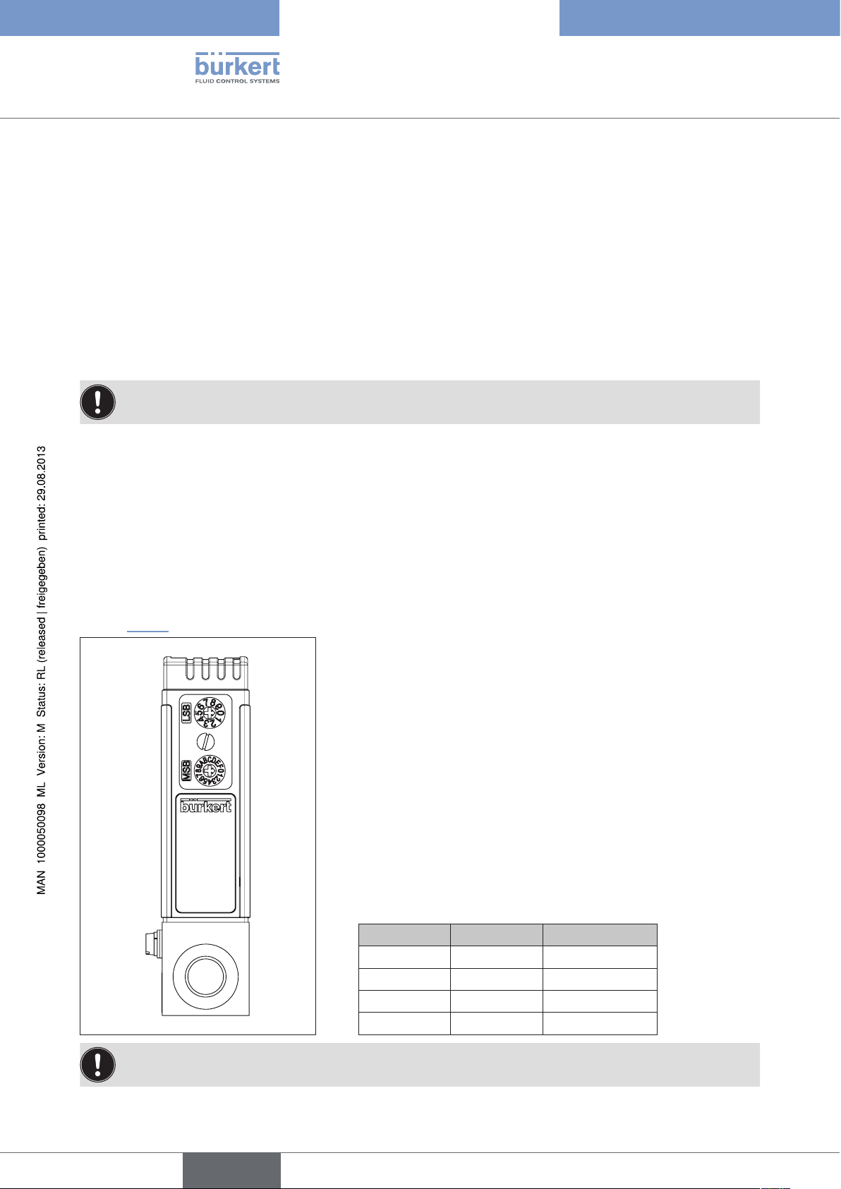
4.1.2. Devices with rotary switch for address setting
When the device is turned on, the address set as the slave address on the rotary switches is applied. Valid
addresses are:
• PROFIBUS 0 … 126
• DeviceNet 0 … 63
• CANopen 1 … 127
If the address has been set outside the permissible range, the address setting has the validity as described in
section “4.1.1”.
LBS Ones place, x 1
0 – 9 The number
multiplied by 1
MBS Tens place, x 10
0 – 9 The number
multiplied by 10
A → 100
B → 110
C → 120
D → 130
E → 140
F → 150
→ 0 – 9
→ 0 – 90
30
Thus the address consists of LSB + MSB.
MSB LBS Address
0 1 1
6 3 63
A 0 100
C 7 127
If you want to make an address setting with the BUS master and there are rotary switches available, set
the address to a value outside the valid range.
english
Page 31

MFC Family
PROFIBUS DP Start-up
4.2. Technical Data
GSD file BUV10627.GSD
Symbols BUV10627.BMP address 0 – 126
Standard: 126
4.3. DP alarm mode
DP alarm mode is not supported.
Siemens-specific:
Use value "DPV0" in the hardware configurator. There is no change in the communication protocol.
The value changes only the "alarm mode support".
Additional information is available in the Simatic S7 help.
4.4. PROFIBUS PDI/PDOs
You can make all settings required for bus communication in this input window. The important items are the
BUS address of the device (BUS AdrProfibus) and the process data to be send (input SPS or PDIs) and to be
received (output SPS or PDOs). They can be activated and deactivated with the option fields.
→ Apply the changed settings in the menu bar under "Functions" / "Write Data to Device".
No more than 10 process data items may be selected. This includes both process input data items and
process output data items.
english
31
Page 32

MFC Family
PROFIBUS DP Start-up
4.5. Explanation of variables used in cyclic data traffic
Process data Explanation Identifier
Actual value Actual value
(1 word = 2 bytes)
Value range 0 – 1000
Set-point Set-point value
(1 word = 2 bytes)
Value range 0 – 1000
Active gas
(used gas type)
Nominal flow Gas 1 Nominal flow in Nl/min of
Nominal flow Gas 2 Nominal flow in Nl/min of
Status limits
Status errors
Status others
Status LEDs
Status binary outputs
Default values via bus
whose calibration curve is used for control:
gas 1 or gas 2
(1 word = 2 bytes)
Value range 0 – 1
calibration for gas 1
float = 4 bytes
calibration for gas 2
float = 4 bytes
Read only
Bit field for states of device-internal threshold value:
(1 word = 2 bytes)
see “9.1. Description of bit fields”
min. value 0, max. value 65535
Read only
Bit field for device errors that are present.
(1 word = 2 bytes)
see “9.1. Description of bit fields”
min. value 0, max. value 65535
Read only
Bit field for current states in the controller.
(1 word = 2 bytes)
see “9.1. Description of bit fields”
min. value 0, max. value 65535
Read only
Bit field for communication states.
(1 word = 2 bytes)
see “9.1. Description of bit fields”
min. value 0, max. value 65535
Reserved bit field
(1 word = 2 bytes)
see “9.1. Description of bit fields”
Bit field for states of LEDs and binary outputs as they can
be assigned by the bus. To do this, the corresponding
functions must be configured in the device with the
PC program.
(1 word = 2 bytes)
see “9.1. Description of bit fields”
41,40,00 (HEX); PDI
41,40,01 (HEX); PDI
81,40,01 (HEX); PDO
41,40,02 (HEX); PDI
41,83,03 (HEX); PDI
41,83,04 (HEX); PDI
41,40,05 (HEX); PDI
41,40,06 (HEX); PDI
41,40,07 (HEX); PDI
41,40,08 (HEX); PDI
41,40,09 (HEX) PDI
41,40,0B (HEX); PDI
81,40,0B (HEX); PDO
32
english
Page 33

MFC Family
PROFIBUS DP Start-up
Process data Explanation Identifier
Totalizer value Gas 1 Totalizer value of calibration for
gas 1 in Nl.
Float = 4 bytes
Totalizer value Gas 2 Totalizer value of calibration for
gas 2 in Nl.
Float = 4 bytes
Actual value as float
Set-point as float
Control output y2 (2 bytes)
AddMeasureValue Additional value as float (4 bytes)
Xp Additional pressure value (2 bytes)
(4 bytes)
Default: 0 –1 00 %
Parameterization of the unit.
(see also “7.4. S-Analog Sensor Object”)
(4 bytes)
Default: 0 – 100 %
Parameterization of the unit.
(see also “7.6. S-Single Stage Controller Object”)
Only for MFC control output y2 of the controller, in units
per thousand
Value range 0 … 1000
Value as a percentage
This value is only supported by a few MFCs. If the value is
not supported, 0% is returned.
Value in units per thousand
Value range 0 … 1000
41,83,03 (HEX); PDI
41,83,0D (HEX); PDI
41,83,0E (HEX) PDI
81,83,0E (HEX) PDO
81,83,0E (HEX) PDO
41,40,10 (HEX); PDI
41,83,11 (HEX); PDI
41,40,12 (HEX); PDI
This value is only supported by a few MFCs. If the value is
not supported, 0% is returned.
4.6. Acyclic data
See “7. Acyclic Data Transfer with PROFIBUS, DeviceNet and CANopen”
33
english
Page 34

MFC Family
DeviceNet Start-up
5. DEVICENET START-UP
5.1. Terms
DeviceNet
DeviceNet is a field bus system based on the CAN protocol (Controller Area Network). It enables actuators and
sensors (slaves) to be networked with higher-level controllers (master).
The DeviceNet profile "Mass Flow Controller Device" is supported with strict compliance to DeviceNet
specifications.
With DeviceNet it is necessary to differentiate between cyclical or event-driven high-priority process messages
(I/O messages) and acyclical low-priority management messages (explicit messages).
Protocol sequence
The protocol process conforms to the DeviceNet specification Release 2.0.
Technical Data
EDS file
Icons
Baudrate
Address
Process data
BUER8626.EDS
BUER8626.ICO
125, 250, 500 kBit/s
Factory setting 125 kBit/s
0 – 63
Factory setting 63
5 static input assemblies
4 static output assemblies
34
english
Page 35

MFC Family
DeviceNet Start-up
5.2. Configuration of Process Data
5 static input and 2 static output assemblies can be selected to transmit process data via an I/O connection.
These assemblies contain selected attributes combined into one object so that process data can be transmitted
collectively via an I/O connection.
The process data is selected by setting the device parameters Active Input Assembly and Active Output
Assembly or - if supported by the DeviceNet-Master/Scanner - by setting Produced Connection Path and
Consumed Connection Path when an I/O connection is initialized according to the DeviceNet specification.
Assembly Object general
Attribute address
Name Description of the input data attributes
ASS_NumberOfObjects 4, x, 1
ASS_Memberlist 4, x, 2
ASS_Data 4, x, 3
(class, instance
attribute, data type)
Assembly Object
Attribute address
Direction data Description of data attributes
Input / output Not active 4, 0, 3
Input Status byte + Flow(INT) 4, 2, 3
Input Statusbyte + Flow(INT) + Setpoint(INT)
+ ActuatorOverrideByte + ValveDutyCycle(INT)
Output Setpoint(INT) 4, 7, 3
Output ActuatorOverrideByte + Setpoint(INT) 4, 8, 3
Input Flow + status errors 4, 21, 3
Input Flow + status errors + status limits 4, 22, 3
Input Flow + status errors + status limits + status others 4, 23, 3
(class, instance
attribute, data type)
4, 6, 3
5.3. Acyclic data
See “7. Acyclic Data Transfer with PROFIBUS, DeviceNet and CANopen”
english
35
Page 36

MFC Family
CANopen Start-up
6. CANOPEN START-UP
6.1. CANopen general
6.1.1. Terms used
CANopen
CANopen is a field bus system based on the CAN protocol (Controller Area Network).
CANopen is a standard of CAN in Automation (CiA).
The CANopen communication model provides two methods of communication mechanisms:
• Unconfirmed transmission of data blocks of up to 8 bytes to transfer process data (PDO "Process Data Object")
without additional overhead compared to SDO.
• Confirmed transmission of data between two nodes with direct access to entries of the object dictionary
(SDO "Service Data Object") of the addressed node.
Protocol sequence
The protocol sequence complies with CANopen communication profile CiA draft standard 301 V 4.02.
6.1.2. Technical Data
EDS file
Baudrate
Address
Process data
Buerkert_COP8626.EDS
20, 50, 100, 125, 250, 500, 800, 1000 kBit/s
Factory setting 125 kBit/s
1 – 127
Factory setting 127
4 TxPDOs
1 RxPDO
36
english
Page 37

MFC Family
CANopen Start-up
6.1.3. Assignment of process data objects
See “6.4. CANopen – Process Data Transfer”
Predefined ID connection set
CANopen defines a standard identifier allocaton scheme (see table below). These identifiers are available in the
pre-operational state after node initialization.
Object Identifier
NMT 0 hex
SYNC 80 hex
EMERGENCY 80 hex + address
st
TPDO 180 hex + address
1
st
RPDO 200 hex + address
1
nd
TPDO 280 hex + address
2
nd
RPDO 300 hex + address
2
rd
TPDO 380 hex + address
3
rd
RPDO 400 hex + address
3
th
TPDO 480 hex + address
4
th
RPDO 500 hex + address
4
TSDO 580 hex + address
RSDO 600 hex + address
NODE-GUARDING 700 hex + address
6.1.4. Error Control Service
To determine a non-active bus, the master must support one of the two error monitoring types, Node-Guarding or
Heartbeat.
Integration of one of the two error monitoring types, Node-Guarding or Heartbeat, is mandatory.
In error monitoring of a CAN-based network, the NMT object detects local errors within a node. These errors can
result in a reset or change of status, for example. The error definitions are not part of the specification.
Error monitoring occurs periodically during data transfer.
There are two methods of error monitoring:
Node-Guarding
Error monitoring involves the NMT master sending the Node-Guarding telegram. If the NMT slave does not
respond within a defined time or if the communication status of the NMT slave has changed, the NMT master
reports this to its NMT master application.
37
english
Page 38

MFC Family
CANopen Start-up
If runtime monitoring is supported, the slave using the Node-Guarding time and fail factor of its object library to
calculate the reacting time. If runtime monitoring is accessed, the NMT slave informs its local application of the
event. If the values of runtime monitoring and the fail factor are zero (0), no runtime monitoring occurs.
Runtime monitoring of the slave starts as soon as the slave receives the first monitoring request. Usually this
happens during the start phase or later.
Node Guarding is adjustable by the following objects:
Name Description Index, Subindex
CANopen
Node-Guarding Time
(monitoring time)
Read Write
Defines the monitoring time in ms.
Dec: 4108, 0
Hex: 100C, 0
UNSIGNED32
Node-Guarding Fail Factor Read Write
Defines the reacting time for detcting a timeout.
Dec: 4109, 0
Hex: 100D, 0
for example reacting time = monitoring time ×
UNSIGNED32
fail factor.
Heartbeat
With Heartbeat, a cyclical check determines whether the other node is still responding. If there is no Heartbeat
message from the node, the monitoring node is informed. If the heartbeat objects are written with values not
equal to 0, monitoring occurs after the change of status from INITIALIZING to PRE-OPERATIONAL. The Bootup
message is the first one to have the heartbeat message. Using both mechanisms (Node-Guarding and Heartbeat)
simultaneously is not permitted. If the objects of the heartbeat are not equal to zero (0), Heartbeat is used as the
monitoring mechanism.
Heartbeat is adjusted with the following objects:
Name Description Index, Subindex
CANopen
Consumer Heartbeat Time Read
Number of entries 1–127
Dec: 4118, 0
Hex: 1016, 0
UNSIGNED8
Read Write
Bits 31–24: Reserved
Dec: 4118, 1–127
Hex: 1016, 1–7
Bits 23–16: Node ID of generator
Bits 15–0: Heartbeat time
Producer Heartbeat Time Read Write
Defines the monitoring time in ms
FUNSIGNED32
Dec: 4109, 0
Hex: 100D, 0
38
english
Page 39

MFC Family
CANopen Start-up
6.2. CANopen emergency
The emergency functions that are implemented comply with the "CiA draft standards 301".
6.2.1. Emergency machine
A device may be in one of two emergency states (see “Fig. 1: Emergency states”). Emergency objects are sent
depending on transitions. Connections between the emergency status machine and the NMT status machine are
defined in the device profiles.
0
Error-free
1
2
Error occurred
Fig. 1: Emergency states
0 If no error is determined, the device goes into an error-free status after initialization. No error message is
sent.
1 The device determines there is an internal error, which is displayed in the first three bytes of the emer-
gency message (error code and error register). The device goes into error status. An emergency object
is sent with the corresponding error code and error register. The error code is entered in object 1003H
(pre-defined error field).
2 One, but not all errors have disappeared. An emergency message containing error code 0000
(error reset), can be sent with the remaining errors in the error register and in the manufacturer-specific
error field.
3 A new error has occurred in the device. The device remains in the error status and sends an emergency
object with the corresponding error code. The new error code is entered at the upper end of the array of
error codes (1003H). It must be guaranteed that error codes are sorted by time (oldest error - highest
subindex; see “Object 1003h: Pre-defined error field”).
4 All errors have been eliminated. The device goes into error-free status and sends an emergency object
with the error code "Reset error / no error".
4
3
english
39
Page 40

MFC Family
CANopen Start-up
6.2.2. Diagnostic object data
The diagnostic telegram consists of 8 bytes with the data shown in the following illustration:
Diagnostic object data.
Byte 0 1 2 3 4 5 6 7
Table of
Contents
Emergency error code
(see “Table of diag-
nostic error”, page
42)
The following two items are added to all errors:
Object 1001h: Error register
Error
register
(object
1001H)
Manufacturer-specific error field
Name
Error register All errors that occur on the
Description of the input
data attribute
device are mapped
Index, Subindex
Dec: 4097, 0
Hex: 1001, 0
on this object.
UNSIGNED8
This object is an error register for the device. The device is able to represent internal errors in this byte.
This entry is mandatory for all devices. It is part of an emergency object.
Bit M/O Description
0 M General error
1 O Current
2 O Voltage
3 O Temperature
4 O Communication error (overflow, error status)
5 O Device-specific
6 O Reserved (always 0)
7 O Manufacturer-specific
40
If a bit is set to 1, the specified error has occurred. The only mandatory error that must be indicated is a general
error. A general error is indicated in every error situation.
english
Page 41

MFC Family
CANopen Start-up
Object 1003h: Pre-defined error field
Name
Error Register The object contains errors that have occurred in the
Description of the input
data attribute
device.
Index, Subindex
Dec: 4099, 0-10
Hex: 1003, 0-A
UNSIGNED32
The object for index 1003h contains errors that have occurred in the device and were indicated by the emergency
object. Thus it returns an error history.
1. The entry for subindex 0 contains the number of actual errors that occurred in the array. Errors are recorded in
the array beginning at subindex 1.
2. The most recent error is saved in subindex 1, while older errors have been moved further down in the list.
3. Writing a "0" to subindex 0 deletes the entire error history (clears the array). Values greater than 0 must not be
be written. This results in an abort message (error code: 0609 0030h).
4. Error numbers are of type UNSIGNED32 and consist of a 16-bit error code and an additional 16-bit infor-
mation field which is manufacturer-specific. The 2 lower-order bytes (LSB) contain the error code, while
the 2 higher-order bytes contain the additional information (MSB). If the object is supported, it must consist of
at least two different entries: the length entry at subindex 0h and at least one error for subindex 1H.
MSBByte
Additional information
Fig. 2: Structure of the pre-defined error field
LSB
Error code
english
41
Page 42

The following table gives an overview of implemented diagnostic error codes:
Table of diagnostic error
MFC Family
CANopen Start-up
Error description Emergency
Error code
Content of error
register
(object 1001H)
Content of the
pre-defined error
field
(object 1003H)
Hex Hex Hex
Dec
Current out of range 2200 03 00002200
8704
Error LED
>power LED<
Error LED
>communication LED<
Error LED
>limit LED<
FF00 81 0001FF00
130816
FF00 81 0002FF00
196352
FF00 81 0003FF00
261888
Error LED FF00 81 0004FF00
327424
Error BinOut
>BinOut 1<
Error BinOut
>BinOut 2<
FF10 81 0001FF10
130832
FF10 81 0002FF10
196368
Error internal supply voltage 3200 05 00003200
Content of the manufacturer-specific
error field
Hex
Byte 0: 01
Byte 0: 02
Byte 0: 03
Byte 0: 04
Byte 0: 01
Byte 0: 02
42
12800
Error sensor supply voltage 3210 05 00003210
12816
Error sensor fault 5030 21 00005030
20528
Error after autotune FF20 81 0000FF20
65312
Error bus module MFI FF30 81 0000FF30
65328
Stack overflow 6100 21 00006100
24832
CAN queue overrun 8110 01 00008110
33040
CAN in error passive mode 8210 11 00008210
33296
english
Page 43

MFC Family
CANopen Start-up
6.3. CANopen – Service Data Transfer
Data transfer between two nodes is described in the client/server model. An SDO client (initiating node) has
direct access to individual entries in the object directory of an SDO server and is able to upload or download data
records of any length to or from a server. The data record to be transferred can be specified by indicating a 16-bit
index and 8-bit subindex. Since one message identifier is required for each transfer direction, two CAN identifiers
are required for a connection between an SDO client and an SDO server. The connection between a client and a
server is also referred to as an SDO channel.
The Bürkert field device has an SDO channel and supports the following transfer types:
Segmented Transfer
Segmented transfer makes it possible to transfer 7 bytes per transfer sequence. At the beginning, an initialization
sequence a 16-bit index and 8-bit subindex is transferred. This is followed by confirmed, segmented transfer of
data.
1)
Expedited
Transfer
Expedited transfer allows for faster transfer of 4 bytes per transfer sequence. It is normally used whenever the
size of the data being transferred does not exceed 4 bytes.
An SDO message is structured as follows:
ID DLC Byte1 Byte2 Byte3 Byte4 Byte5 Byte6 Byte7 Byte8
- 8 CMD Index Subindex Data bytes
The transfer is specified in byte 1 by control bytes. For an overview of the meaning of different control bytes, see
the following table.
Process CMD Note
Master requests data from slave 40h
Slave responds 42h (valid data bytes not specified)
43h (4 valid data bytes)
47h (3 valid data bytes)
4Bh (2 valid data bytes)
4Fh (1 valid data byte)
Master writes to slave 22h (valid data bytes not specified)
23h (4 valid data bytes)
27h (3 valid data bytes)
2Bh (2 valid data bytes)
2Fh (1 valid data byte)
Slave responds 60h
1)
Expedited: accelerated
43
english
Page 44

MFC Family
CANopen Start-up
6.4. CANopen – Process Data Transfer
All available process data objects are mapped. Only selected process data objects have valid values.
6.4.1. Received PDOs
Received PDOs are data that has been received by the device (MFC). This is output data as seen by the PLC.
Received PDO
Byte RxPDO0
0 Lower byte
1 Higher-order byte
2 Lower byte
3 Higher-order byte
4 Byte 0
5 Byte 1
6 Byte 2
7 Byte 3
The following bit field makes it possible to select objects for the process data transfer.
Process data Explanation Identification
BUS_PDOs Bit field to select objects for the
process data transfer (Tx)
Bit 0 Bit 1 Set-point value
Bit 2 Bit 3 Bit 4 Bit 5 Bit 6 Bit 7 Bit 8 Bit 9 Bit 10 Bit 11 Default values via bus
Bit 12 Bit 13 Bit 14 Bit 15 Set-point value as Float
Set-point value
Set binary output via bus
Set-point value as Float
Dec: 16896, 1
Hex: 4200, 1
INTEGER16
44
english
Page 45

MFC Family
CANopen Start-up
The bit field can be defined by SDO access.
ID DLC Byte0 Byte1 Byte2 Byte3 Byte4 Byte5 Byte6 Byte7
600h+ID 8 22 4200H 01H Bit field
6.4.2. Transmitted PDOs
Transmitted PDOs are data that has been sent to the device (MFC). This is input data as seen by the PLC.
Transmitted PDO
Byte TxPDO0 TxPDO1 TxPDO2 TxPDO3
0 Byte 0
1 Byte 1 Byte 1 Byte 1 Byte 1
Actual
value
Byte 0
Status
limits
Byte 0
Totalizer
(of the
2 Byte 0
Set-
point
3 Byte 1 Byte 1 Byte 3 Byte 3
4 Byte 0
5 Byte 1 Byte 1 Byte 1 Byte 1
6 Byte 0
7 Byte 1 Byte 3 Byte 3 Byte 3
value
Active
gas
Status
errors
Byte 0
Status
Byte 2 Byte 2
others
Byte 0
Byte 0
AddMea-
Byte 2 Byte 2 Byte 2
sureValue
active gas)
Flow rate
(of the
active gas)
The following bit field makes it possible to select objects for the process data transfer.
Byte 0
Actual value
as Float
Byte 0
Set-point
value as
Float
english
45
Page 46

MFC Family
CANopen Start-up
Process data Explanation Identification
BUS_PDIs Bit field to select objects for the
process data transfer (Tx)
Bit 0 Actual value
Bit 1 Set-point value
Bit 2 Active gas
Bit 3 Nominal flow gas 1
Bit 4 Nominal flow gas 2
Bit 5 Status limits
Bit 6 Status errors
Bit 7 Status others
Bit 8 Bit 9 Bit 10 Bit 11 Bit 12 Totalizer value gas 1
Bit 13 Totalizer value gas 1
Bit 14 Actual value as Float
Bit 15 Set-point value as Float
Bit 16 Bit 17 AddMeasureValue
Bit 18 Xp (not supported yet)
Dec: 16896, 2
Hex: 4200, 2
UNSIGNED32
46
The bit field can be defined by SDO access.
ID DLC Byte0 Byte1 Byte2 Byte3 Byte4 Byte5 Byte6 Byte7
600h+ID 8 22 4200H 02H Bit field
english
Page 47

MFC Family
CANopen Start-up
6.4.3. Transmission Type
Index Subindex Parameter Length Access
1800h 0 Number of subindices Read
1 COB ID used by the PDO Read/write
2 Transmission Type Read/write
5 Inhibit Time Read/write
The transfer type (subindex 2) defines the type of transmission/reception for the PDO.
The following table explains how the entry is used. If an attempt is made to set the value of the variable to an entry
that is not supported, an error message (abort code: 0609 0030h) is generated.
Transmission
Type
Trigger condition of the PDO
(B= both required, E= one required)
PDO
transfer
SYNC RTR Event
0 B - B synchronous, acyclic
1-240 E - - synchronous, cyclic
241-251 - - - reserved
252 B B - synchronous, after RTR
253 - E - asynchronous, after RTR
254 - E E asynchronous, manufacturer-
specific event
255 - E E asynchronous, device-specific event
english
47
Page 48

MFC Family
CANopen Start-up
6.4.4. Overview of the mapped objects
Process data Explanation Identification
Actual value Actual value
(1 word = 2 bytes)
Value range 0 – 1000
Set-point Set-point value
(1 word = 2 bytes)
Value range 0 – 1000
Active gas Calibration of this gas is used for control,
gas 1 or gas 2
(1 word = 2 bytes) value range 0 – 1
Nominal flow Gas 1 Nominal flow in Nl/min of
calibration for gas 1
float = 4 bytes
Nominal flow Gas 2 Nominal flow in Nl/min of
calibration for gas 2
float = 4 bytes
RX (receive)
Dec: 12288, 1
Hex: 3000, 1
INTEGER16
Tx, Rx
Dec: 12288, 2
Hex: 3000, 2
UNSIGNED16
RX (receive)
Dec: 12288, 3
Hex: 3000, 3
UNSIGNED16
RX (receive)
Dec: 12288, 4
Hex: 3000, 4
REAL32
RX (receive)
Dec: 12288, 5
Hex: 3000, 5
48
Status limits
Status errors
Status others
Bit field for states of device-internal threshold
value:
(1 word = 2 bytes)
see “9.1. Description of bit fields”
Bit field for device errors that are present.
(1 word = 2 bytes)
see “9.1. Description of bit fields”
Bit field for current states in the controller.
(1 word = 2 bytes)
see “9.1. Description of bit fields”
REAL32
RX (receive)
Dec: 12288, 6
Hex: 3000, 6
UNSIGNED16
RX (receive)
Dec: 12288, 7
Hex: 3000, 7
UNSIGNED16
RX (receive)
Dec: 12288, 8
Hex: 3000, 8
UNSIGNED16
english
Page 49

MFC Family
CANopen Start-up
Process data Explanation Identification
Default values via bus
Bit field for states of LEDs and binary outputs if
they can be assigned by the bus.
To do this, the relevant functions must be configured in the device with the PC program.
(1 word = 2 bytes)
see “9.1. Description of bit fields”
Totalizer value Gas 1 Totalizer value of calibration for gas 1 in Nl.
Float = 4 bytes
Totalizer value Gas 2 Totalizer value of calibration for gas 2 in Nl.
Float = 4 bytes
Actual value as float
Actual value as Float (4 bytes)
Value range 0 – 1000
Other units can be parameterized by the value
of the flow unit from the “7.4. S-Analog Sensor
Object”.
Tx (send)
Dec: 12288, 12
Hex: 3000, C
UNSIGNED16
RX (receive)
Dec: 12288, 13
Hex: 3000, D
REAL32
RX (receive)
Dec: 12288, 14
Hex: 3000, E
REAL32
Tx, Rx
Dec: 8960, 3
Hex: 2300, 3
REAL32
e.g. units per thousand, Nl/min and the calibrated
unit
Set-point as float
Set-point value as Float (4 bytes)
Value range 0 – 1000
Other units can be parameterized by the value of
the flow unit from the “7.6. S-Single Stage Controller Object”.
e.g. units per thousand, Nl/min and the calibrated
unit
AddMeasureValue Read only
Additional value as float (4 bytes)
Value as a percentage
This value is only supported by a few MFCs. If the
value is not supported, 0% is returned.
Xp (currently not
supported)
Read only
Additional pressure value (2 bytes)
Value in units per thousand
Value range 0 – 1000
This value is only supported by a few MFCs. If the
value is not supported, 0% is returned.
RX (receive)
Dec: 8448, 4
Hex: 2100, 4
REAL32
Dec: 12288, 46
Hex: 3000, 2E
REAL32
Dec: 12288, 47
Hex: 3000, 2F
UNSIGNED16
english
49
Page 50

MFC Family
CANopen Start-up
6.5. CANopen – Communication Object
Name Description of the input data attribute Index, Subindex
CANopen
Node ID Read Write
Bus address
Address by which the CANopen master
communicates with the device.
1 – 127
Default: 127
Baudrate Read Write
0 - 1000 kb
Dec: 16384, 1
Hex: 4000, 1
UNSIGNED8
Dec: 16384, 1
Hex: 4000, 1
1 – 800 kb
2 – 500 kb
3 – 250 kb
4 – 125 kb
5 – 100 kb
6 – 50 kb
7 – 20 kb
8 - 10 kb
Default: 4 = 125 kb
To activate modified values, an "NMT" reset must be sent.
If values are changed with the MassFlowCommunicator program, a hardware reset is required.
UNSIGNED8
6.6. Acyclic data
See “7. Acyclic Data Transfer with PROFIBUS, DeviceNet and CANopen”
50
english
Page 51

MFC Family
Acyclic Data Transfer with
PROFIBUS, DeviceNet and CANopen
7. ACYCLIC DATA TRANSFER WITH PROFIBUS,
DEVICENET AND CANOPEN
7.1. CANopen-Manufactory Object
Manufactory Object
Name
Device Type Read only
Device Name Read only
Hardware Version Read only
Software Version Read only
Description of the input data attributes Index, Subindex
CANopen profile
No profile supported
Entry 0
Device name
Hardware version
e.g. "A"
Software version
e.g. "A01.00"
7.2. CANopen-Identity Object
CANopen
Dec: 4096, 0
Hex: 1000, 0
UNSIGNED32
Dec: 4104, 0
Hex: 1008, 0
VISIBLE_STRING
Dec: 4105, 0
Hex: 1009, 0
VISIBLE_STRING
Dec: 4106, 0
Hex: 100A, 0
VISIBLE_STRING
Identity Object
Name Description of the input data attributes Index, Subindex
CANopen
Vendor ID Read only
vendor's ID number.
Bürkert's CANopen vendor ID 39h
Product Code Read only
product code of the device.
Revision Number Read only
This is a structure of two UNSIGNED16 values.
It is the Bürkert CANopen communications version
number.
Serial Number Read only
The device serial number specified on the rating plate.
Dec: 4120, 1
Hex: 1018, 1
UNSIGNED32
Dec: 4120, 2
Hex: 1018, 2
UNSIGNED32
Dec: 4120, 3
Hex: 1018, 3
UNSIGNED32
Dec: 4120, 4
Hex: 1018, 4
UNSIGNED32
51
english
Page 52

7.3. DeviceNet S-Identity Object
S-Identity Object
Name Description of the input data attributes
Vendor ID Read only
vendor's ID number.
Bürkerts DeviceNet vendor ID 57h
Device Type Read only
Numeric device identifier
Identification of the general product type.
This is type 0 (generic device).
Product Code Read only
The product code is 2, corresponding to the eds file.
MFC Family
Acyclic Data Transfer with
PROFIBUS, DeviceNet and CANopen
Attribute address
(class, instanceattribute; data type)
DVN
Dec: 1, 1, 1
Hex: 1, 1, 1
UINT
Dec: 1, 1, 2
Hex: 1, 1, 2
UINT
Dec: 1, 1, 3
Hex: 1, 1, 3
Revision Read only
Revision of the element representing the identity
object. This is a structure of two bytes.
Status Read only
Combined status of the device.
Serial Number Read only
Serial number that is unique for all Bürkert devices.
Product Name Read only
MFC/MFM
UINT
Dec: 1, 1, 4
Hex: 1, 1, 4
WORD
Dec: 1, 1, 5
Hex: 1, 1, 5
WORD
Dec: 1, 1, 6
Hex: 1, 1, 6
UDINT
Dec: 1, 1, 7
Hex: 1, 1, 7
SHORT_STRING
52
english
Page 53

MFC Family
Acyclic Data Transfer with
PROFIBUS, DeviceNet and CANopen
7.4. S-Analog Sensor Object
S-Analog Sensor Object
Name Description of the input data
attributes
Data Type Read Write
Describes the data format of the
actual value and the "Flow Full
Scale" (nominal flow)
Hex
0xC3 INT
0xCA REAL
Data Units
Reading Valid Read only
Read Write
min. value 2048,
max. value 4103
list of units see
“9.2. Table of units”
"% "
"Units per thousand"
and the calibrated device unit
Min. value 0, max. value 1
Attribute address
(class, instanceattribute; data type)
DVN DPV1 CANopen
Dec: 49, 1, 3
Hex: 31, 1, 3
USINT
Dec: 49, 1, 4
Hex: 31, 1, 4
UINT
Dec: 49, 1, 5
Hex: 31, 1, 5
Slot, Index Index, Subindex
Dec: 1, 3
Hex: 1, 3
Dec: 1, 4
Hex: 1, 4
Dec: 1, 5
Hex: 1, 5
Dec: 8448, 1
Hex: 2100, 1
UNSIGNED8
Dec: 8448, 2
Hex: 2100, 2
UNSIGNED16
Dec: 8448, 3
Hex: 2100, 3
Actual value Read only
Depends on the settings under
data type and data units.
Status Read only
This is not supported yet.
The return value is always 0.
BOOL
Dec: 49, 1, 6
Hex: 31, 1, 6
INT
Or
REAL
Dec: 49, 1, 7
Hex: 31, 1, 7
BYTE
Dec: 1, 6
Hex: 1, 6
Dec: 1, 7
Hex: 1, 7
UNSIGNED8
Dec: 8448, 4
Hex: 2100, 4
INTEGER16
Or
Dec: 8448, 5
Hex: 2100, 5
REAL32
Dec: 8448, 6
Hex: 2100, 6
UNSIGNED8
53
english
Page 54

S-Analog Sensor Object
MFC Family
Acyclic Data Transfer with
PROFIBUS, DeviceNet and CANopen
Name Description of the input data
attributes
Flow Full
Scale
Read only
Depends on the settings under
data type and data units.
Attribute address
(class, instanceattribute; data type)
DVN DPV1 CANopen
Dec: 49, 1, 10
Hex: 31, 1, A
INT
Or
REAL
7.5. S-Analog Actuator Object
S-Analog Actuator Object
Name Description of the input data
attributes
Data Type
Data Units Read Write
Read Write
Describes the data format of the
"value"
Hex
0xC3 INT
0xCA REAL
min. value 2048
max. value 4103
Possible units are:
"% "
"Units per thousand"
0x800 "Units per thousand"
0x1007 "% "
Attribute address
(class, instance
attribute; data
type)
DVN DPV1 DPV1
Dec: 50, 1, 3
Hex: 32, 1, 3
USiNT
Dec: 50, 1, 4
Hex: 32, 1, 4
UINT
Slot, Index Index, Subindex
Dec: 1, 10
Hex: 1, A
Slot, Index Index, Subindex
Dec: 1, 53
Hex: 1, 35
Dec: 1, 54
Hex: 1, 36
Dec: 8448, 7
Hex: 2100, 7
INTEGER16
Or
Dec: 8448, 8
Hex: 2100, 8
REAL32
Dec: 8704, 1
Hex: 2200, 1
UNSIGNED8
Dec: 8704, 2
Hex: 2200, 2
UNSIGNED16
54
english
Page 55

MFC Family
Acyclic Data Transfer with
PROFIBUS, DeviceNet and CANopen
S-Analog Actuator Object
Name Description of the input data
attributes
Actuator
Override
(overwrite
control output)
Read Write
0 Normal operation of the controller and binary input controls
the valve
1 off / closed
2 on / open -flow is restricted
by the pressure and orifice of the
valve
3 Hold function active for control
output to the valve
64 Valve control output is controlled by the set-point value. The
min. and max. ramp up and down
times (ramps, etc.) apply.
Read only
65 Similar to 64, except that the
percentage entry for the control
output is only within the working
range of the valve
66 Calibration mode active
67 Autotune mode active
68 Safety mode active
Valve Value
(control output
to valve)
Read only
The valve duty cycle.
The value format depends on the
data type.
The value unit is defined by the
value of the unit.
Attribute address
Slot, Index Index, Subindex
(class, instance
attribute; data
type)
DVN DPV1 DPV1
Dec: 50, 1, 5
Hex: 32, 1, 5
USINT
Dec: 50, 1, 6
Hex: 32, 1, 6
INT
Dec: 1, 55
Hex: 1, 37
Dec: 1, 56
Hex: 1, 38
Dec: 8704, 3
Hex: 2200, 3
UNSIGNED8
Dec: 8704, 4
Hex: 2200, 4
INTEGER16
Or
REAL
Or
Status Read only
This is not supported yet.
The return value is always 0.
Dec: 50, 1, 7
Hex: 32, 1, 7
BYTE
Dec: 1, 57
Hex: 1, 39
english
Dec: 8704, 5
Hex: 2200, 5
REAL32
Dec: 8704,6
Hex: 2200, 6
UNSIGNED8
55
Page 56

7.6. S-Single Stage Controller Object
S-Single Stage Controller Object
MFC Family
Acyclic Data Transfer with
PROFIBUS, DeviceNet and CANopen
Name Description of the input data
attributes
Data Type Read Write
Describes the data type of the
set-point value
Hex
0xC3 INT0
0xCA REAL
Data Units
Set-point Read Write
Read Write
min. value 2048,
max. value 4103
list of units see
“9.2. Table of units”
"% "
"Units per thousand"
and the calibrated device unit
The value format depends on the
data type.
The value unit is defined by the
value of the unit.
Attribute address
(class, instance
attribute; data
type)
DVN DPV1 CANopen
Dec: 51, 1, 3
Hex: 33, 1, 3
USINT
Dec: 51, 1, 6
Hex: 33, 1, 6
UINT
Dec: 51, 1, 6
Hex: 33, 1, 6
INT
Or
REAL
Slot, Index Index, Subindex
Dec: 1, 103
Hex: 1, 67
Dec: 1, 104
Hex: 1, 68
Dec: 1, 106
Hex: 1, 6A
Dec: 8960, 1
Hex: 2300, 1
UNSIGNED8
Dec: 8960, 2
Hex: 2300, 2
UNSIGNED16
Dec: 8960, 3
Hex: 2300, 3
INTEGER16
Or
Dec: 8960, 4
Hex: 2300, 4
56
Status Read only
This is not supported yet.
The return value is always 0.
english
Dec: 51, 1, 6
Hex: 33, 1, 6
BYTE
Dec: 1, 107
Hex: 1, 6B
REAL32
Dec: 8960, 5
Hex: 2300, 5
UNSIGNED8
Page 57

MFC Family
Acyclic Data Transfer with
PROFIBUS, DeviceNet and CANopen
7.7. Bürkert General Description Object
Bürkert General Description Object
Name Description of the input data
attributes
Device Ident
Number
Device Serial
Number
Device Type Read only
Ident Number
printed circuit
board
Revision
Number
Hardware
(Hardware
revision)
Read only
Bürkert identifications number
of the device
min. value 0,
max. value 99999999
Read only
Bürkert serial number of the
device
min. value 0,
max. value 4294967295
Bürkert type number of the
device
min. value 0, max. value 65535
Read only
Ident number of the printed
circuit board
min. value 0,
max. value 99999999
Read only
Revision number of the printed
circuit board
min. value A‘, max. value Z‘
Attribute address
(class, instance
attribute; data type)
DVN DPV1 CANopen
Dec: 101, 1, 1
Hex: 65, 1, 1
UDINT
Dec: 101, 1, 2
Hex: 65, 1, 2
UDINT
Dec: 101, 1, 3
Hex: 65, 1, 3
UINT
Dec: 101, 1, 4
Hex: 65, 1, 4
UDINT
Dec: 101, 1, 5
Hex: 65, 1, 5
USINT
Slot, Index Index, Subindex
Dec: 0, 101
Hex: 0, 65
Dec: 0, 102
Hex: 0, 66
Dec: 0, 103
Hex: 0, 67
Dec: 0, 104
Hex: 0, 68
Dec: 0, 105
Hex: 0, 69
Dec: 8192, 1
Hex: 2000, 1
UNSIGNED32
Dec: 8192, 2
Hex: 2000, 2
UNSIGNED32
Dec: 8192, 3
Hex: 2000, 3
UNSIGNED16
Dec: 8192, 4
Hex: 2000, 4
UNSIGNED32
Dec: 8192, 5
Hex: 2000, 5
UNSIGNED8
7.8. Bürkert MFC Family Object
Bürkert MFC Family Object
Name Description of the input
data attributes
Actual value
(actual value
(x))
Set-point
(set-point
(w))
Read only
Value in units per thousand
of the active gas
min. value 0, max. value 1000
Read Write
Set-point value in units per
thousand for the active gas
min. value 0, max. value 1000
Attribute address
(class, instance
attribute; data type)
DVN DPV1 CANopen
Dec: 110, 1, 1
Hex: 6E, 1, 1
UINT
Dec: 110, 1, 2
Hex: 6E, 1, 2
UINT
Slot, Index Index, Subindex
Dec: 1, 151
Hex: 1, 97
Dec: 1,152
Hex: 1, 98
english
Dec: 12288, 1
Hex: 3000, 1
UNSIGNED16
Dec: 12288, 2
Hex: 3000, 2
UNSIGNED16
57
Page 58

Bürkert MFC Family Object
MFC Family
Acyclic Data Transfer with
PROFIBUS, DeviceNet and CANopen
Name Description of the input
data attributes
Active gas Read Write
calibration of this gas
is used for control.
Gas 1 or gas 2
min. value 0, max. value 1
Flow rate
gas 1
Read only
Nominal flow in Nl/min for
calibration of gas 1
min. value 0,
max. value 1.00E+39
Flow rate
gas 2
Read only
Nominal flow in Nl/min for
calibration of gas 2
min. value 0,
max. value 1.00E+39
Status limits
Read only
Bit field for the status of
device-internal threshold
value.
See “9.1. Description of bit
fields”
min. value 0,
max. value 65535
Status errors
Read only
Bit field for device errors
See “9.1. Description of bit
fields”
min. value 0,
max. value 65535
Status others
Read only
Bit field for current
controller states
See “9.1. Description of bit
fields”
min. value 0, max. value 65535
Status LEDs
Read only
Bit field for communication
states
See “9.1. Description of bit
fields”
min. value 0,
max. value 65535
Attribute address
Slot, Index Index, Subindex
(class, instance
attribute; data type)
DVN DPV1 CANopen
Dec: 110, 1, 3
Hex: 6E, 1, 3
UINT
Dec: 110,1,4
Hex: 6E, 1, 4
REAL
Dec: 110, 1, 5
Hex: 6E, 1, 5
REAL
Dec: 110, 1, 6
Hex: 6E, 1, 6
WORD
Dec: 110, 1, 7
Hex: 6E, 1, 7
WORD
Dec: 110, 1, 8
Hex: 6E, 1, 8
WORD
Dec: 110, 1, 9
Hex: 6E, 1, 9
WORD
Dec: 1,153
Hex: 1, 99
Dec: 1,154
Hex: 1, 9A
Dec: 1,155
Hex: 1, 9B
Dec: 1, 156
Hex: 1, 9C
Dec: 1, 157
Hex: 1, 9D
Dec: 1, 158
Hex: 1, 9E
Dec: 1, 159
Hex: 1, 9F
Dec: 12288, 3
Hex: 3000, 3
UNSIGNED16
Dec: 12288, 4
Hex: 3000, 4
REAL32
Dec: 12288, 5
Hex: 3000, 5
REAL32
Dec: 12288, 6
Hex: 3000, 6
UNSIGNED16
Dec: 12288, 7
Hex: 3000, 7
UNSIGNED16
Dec: 12288, 8
Hex: 3000, 8
UNSIGNED16
Dec: 12288, 9
Hex: 3000,9
UNSIGNED16
58
english
Page 59

MFC Family
Acyclic Data Transfer with
PROFIBUS, DeviceNet and CANopen
Bürkert MFC Family Object
Name Description of the input
data attributes
Status binary
outputs
Read only
Bit field for states of binary
outputs (reserved)
See “9.1. Description of bit
fields”
min. value 0,
max. value 65535
Status
Hardware
Read only
Bit field for the current status
of binary input and output
and the status of LEDs
See “9.1. Description of bit
fields”
min. value 0,
max. value 65535
Set BinOut
via bus
Read Write
Bit field for states of LEDs
and binary outputs and for
configuring them via BUS.
The behavior of the device
must be previously configured with the PC software.
MenuViews → DeviceSettings → Assignments of
Inputs and Outputs.
min. value 0,
max. value 65535
Totalizer
gas 1
Read Write
Totalizer value in Nl from the
calibration for gas 1
min. value 0,
max. value 1.00E+39
Totalizer
gas 2
Read Write
Totalizer value in Nl from the
calibration for gas 2
min. value 0,
max. value 1.00E+39
Max ramp
time up
Read Write
You can set the time delay
(0 – 100 ⇒ 0 – 10 seconds)
that delays a set-point value
jump from 0% to 100%
using a ramp function.
min. value 0, max. value 100
Attribute address
Slot, Index Index, Subindex
(class, instance
attribute; data type)
DVN DPV1 CANopen
Dec: 110, 1, 10
Hex: 6E, 1, A
WORD
Dec: 110, 1, 11
Hex: 6E, 1, B
WORD
Dec: 110, 1, 12
Hex: 6E, 1, C
WORD
Dec: 110, 1, 13
Hex: 6E, 1, D
REAL
Dec: 110, 1, 14
Hex: 6E, 1, E
REAL
Dec: 110, 1, 15
Hex: 6E, 1, F
UINT
Dec: 1, 160
Hex: 1, A0
Dec: 1, 161
Hex: 1, A1
Dec: 1, 162
Hex: 1, A2
Dec: 1, 163
Hex: 1, A3
Dec: 1, 164
Hex: 1, A4
Dec: 1, 165
Hex: 1, A5
Dec: 12288, 10
Hex: 3000, A
UNSIGNED16
Dec: 12288, 11
Hex: 3000, B
UNSIGNED16
Dec: 2288, 12
Hex: 3000, C
UNSIGNED16
Dec: 12288, 13
Hex: 3000, D
REAL32
Dec: 2288, 14
Hex: 3000, E
REAL32
Dec: 12288, 15
Hex: 3000, F
UNSIGNED16
english
59
Page 60

Bürkert MFC Family Object
MFC Family
Acyclic Data Transfer with
PROFIBUS, DeviceNet and CANopen
Name Description of the input
data attributes
Max ramp
time down
Read Write
You can set the time delay
(0 – 100 ⇒ 0 – 10 seconds)
that delays a set-point value
jump from 100% to 0%
using a ramp function.
min. value 0, max. value 10
Dynamic
behavior of
the control
Read Write
Change in the dynamic
behavior of the controller.
Can be set slower
(values <1) and faster
(values > 1) than the factory
setting (value = 1)
(step width 0,1)
min. value 0.1, max. value 2
x_Limit1 Read Write
Limit value for the first
threshold value from the
process value (x) in units per
thousand for the active gas
min. value 0, max. value 1000
x_Limit1 Hyst Read Write
Hysteresis for x_Limit1 in
units per thousand
min. value 0, max. value 1000
Attribute address
Slot, Index Index, Subindex
(class, instance
attribute; data type)
DVN DPV1 CANopen
Dec: 110, 1, 6
Hex: 6E, 1, 10
UINT
Dec: 110, 1, 17
Hex: 6E, 1, 11
REAL
Dec: 110, 1, 18
Hex: 6E, 1, 12
UINT
Dec: 110, 1, 19
Hex: 6E, 1, 13
UINT
Dec: 1, 166
Hex: 1, A6
Dec: 1, 167
Hex: 1, A7
Dec: 1, 168
Hex: 1, A8
Dec: 1, 169
Hex: 1, A9
Dec: 12288, 16
Hex: 3000, 10
UNSIGNED16
Dec: 12288, 17
Hex: 3000, 11
REAL32
Dec: 12288, 18
Hex: 3000, 12
UNSIGNED16
Dec: 12288, 19
Hex: 3000, 13
UNSIGNED16
60
x_Limit2 Read Write
Limit value for the second
threshold value from the
process value (x) in units per
thousand for the active gas
min. value 0, max. value 1000
x_Limit2 Hyst Read Write
Hysteresis for x_Limit2 in
units per thousand
min. value 0, max. value 1000
y2_Limit1 Read Write
Limit value for the first
threshold value from the
control output (y2) in units
per thousand (only via MFCs)
min. value 0, max. value 1000
english
Dec: 110, 1, 20
Hex: 6E, 1, 14
UINT
Dec: 110, 1, 21
Hex: 6E, 1, 15
UINT
Dec: 110, 1, 22
Hex: 6E, 1, 16
UINT
Dec: 1, 170
Hex: 1, AA
Dec: 1, 171
Hex: 1, AB
Dec: 1, 172
Hex: 1, AC
Dec: 12288, 20
Hex: 3000, 14
UNSIGNED16
Dec: 12288, 21
Hex: 3000, 15
UNSIGNED16
Dec: 12288, 22
Hex: 3000, 16
UNSIGNED16
Page 61

MFC Family
Acyclic Data Transfer with
PROFIBUS, DeviceNet and CANopen
Bürkert MFC Family Object
Name Description of the input
data attributes
y2_Limit1
Hyst
Read Write
Hysteresis for y2_Limit1 in
units per thousand
min. value 0, max. value 1000
y2_Limit2 Read Write
Limit value for the second
threshold value from the
control output (y2) in units
per thousand
(only via MFCs)
min. value 0, max. value 1000
y2_Limit2
Hyst
Read Write
Hysteresis for y2_Limit2 in
units per thousand
min. value 0, max. value 1000
Gas1
Totalizer
Limit1
Read Write
Limit value for the first
threshold value of the
totalizer for gas1 in Nl/min
min. value 0,
max. value 1.00E+39
Gas1
Totalizer
Limit2
Read Write
Limit value for the second
threshold value from the
totalizer for gas1 in Nl/min
min. value 0,
max. value 1.00E+39
Gas2
Totalizer
Limit1
Read Write
Limit value for the first
threshold value of the
totalizer for gas2 in Nl/min
min. value 0,
max. value 1.00E+39
Gas2
Totalizer
Limit2
Read Write
Limit value for the second
threshold value from the
totalizer for gas2
in Nl/min
min. value 0,
max. value 1.00E+39
Attribute address
Slot, Index Index, Subindex
(class, instance
attribute; data type)
DVN DPV1 CANopen
Dec: 110, 1, 23
Hex: 6E, 1, 17
UINT
Dec: 110, 1, 24
Hex: 6E, 1, 18
UINT
Dec: 110, 1, 25
Hex: 6E, 1, 19
UINT
Dec: 110, 1, 26
Hex: 6E, 1, 1A
REAL
Dec: 110, 1, 27
Hex: 6E, 1, 1B
REAL
Dec: 110, 1, 28
Hex: 6E, 1, 1C
REAL
Dec: 110, 1, 29
Hex: 6E, 1, 1D
REAL
Dec: 1, 173
Hex: 1, AD
Dec: 1, 174
Hex: 1, AE
Dec: 1, 175
Hex: 1, AF
Dec: 1, 176
Hex: 1, B0
Dec: 1, 177
Hex: 1, B1
Dec: 1, 178
Hex: 1, B2
Dec: 1, 179
Hex: 1, B3
Dec: 12288, 23
Hex: 3000, 17
UNSIGNED16
Dec: 12288, 24
Hex: 3000, 18
UNSIGNED16
Dec: 12288, 25
Hex: 3000, 19
UNSIGNED16
Dec: 12288, 26
Hex: 3000, 1A
REAL32
Dec: 12288, 27
Hex: 3000, 1
BREAL32
Dec: 12288, 28
Hex: 3000,1C
REAL32
Dec: 12288, 29
Hex: 3000, 1D
REAL32
english
61
Page 62

Bürkert MFC Family Object
MFC Family
Acyclic Data Transfer with
PROFIBUS, DeviceNet and CANopen
Name Description of the input
data attributes
Gas1
SafeValue
Read Write
Change in the flow rate of
gas1 to which the device is
set in case of an emergency
in the system
(value in units per thousand)
min. value 0, max. value 1000
Gas2
SafeValue
Read Write
Change in the flow rate of
gas2 to which the device is
set in case of an emergency
in the system
(value in units per thousand)
min. value 0, max. value 1000
Binary
output 1
function-limits
Read Write
Determines when binary
output 1 is active. It is a
logical OR operation of all
"Binary output 1 functions"
(in this case: group of limits;
see “Bit field LIMITS” in
“9.1. Description of bit fields”
min. value 0,
max. value 65535
Binary
output 1
functionerrors
Read Write
Determines when binary
output 1 is active. It is a
logical OR operation of all
"Binary output 1 functions"
(in this case: group of errors;
see “Bit field ERRORS” in
“9.1. Description of bit fields”
min. value 0,
max. value 65535
Binary
output 1
functionothers
Read Write
Determines when binary
output 1 is active. It is a
logical OR operation of all
"Binary output 1 functions"
(in this case: group of others;
see “Bit field OTHERS”
in “9.1. Description of bit
fields”) min. value 0,
max. value 65535
Attribute address
Slot, Index Index, Subindex
(class, instance
attribute; data type)
DVN DPV1 CANopen
Dec: 110, 1, 30
Hex: 6E, 1, 1E
UINT
Dec: 110, 1, 31
Hex: 6E, 1, 1F
UINT
Dec: 110, 1, 32
Hex: 6E, 1, 20
WORD
Dec: 110, 1, 33
Hex: 6E, 1, 21
WORD
Dec: 110, 1, 34
Hex: 6E, 1, 22
WORD
Dec: 1, 180
Hex: 1, B4
Dec: 1, 181
Hex: 1, B5
Dec: 1, 182
Hex: 1, B6
Dec: 1, 183
Hex: 1, B7
Dec: 1, 184
Hex: 1, B8
Dec: 12288, 30
Hex: 3000, 1
EUNSIGNED16
Dec: 12288, 31
Hex: 3000, 1F
UNSIGNED16
Dec: 12288, 32
Hex: 3000, 20
UNSIGNED16
Dec: 12288, 33
Hex: 3000, 21
UNSIGNED16
Dec: 12288, 34
Hex: 3000, 22
UNSIGNED16
62
english
Page 63

MFC Family
Acyclic Data Transfer with
PROFIBUS, DeviceNet and CANopen
Bürkert MFC Family Object
Name Description of the input
data attributes
Binary
output 1
mode of
operation
Read Write
Determines the opreting
mode of binary output 1
0: normal, 1: inverse
min. value 0, max. value 1
Binary
output 2
function-limits
Read Write
Determines when binary
output 2 is active. It is a
logical OR operation of all
"Binary output 2 functions"
(in this case: group of limits;
see “Bit field LIMITS” in
“9.1. Description of bit
fields”) min. value 0,
max. value 65535
Binary
output 2
functionerrors
Read Write
Determines when binary
output 2 is active. It is a
logical OR operation of all
"Binary output 2 functions"
(in this case: group of errors;
see “Bit field ERRORS” in
“9.1. Description of bit fields”
min. value 0,
max. value 65535
Binary
output 2
functionothers
Read Write
Determines when binary
output 2 is active. It is a
logical OR operation of all
"Binary output 2 functions"
(in this case: group of others;
see “Bit field OTHERS” in
“9.1. Description of bit
fields”)
min. value 0,
max. value 65535
Binary
output 2
mode of
operation
Read Write
Determines the operating
mode of binary output 2
0: normal, 1: inverse
min. value 0, max. value 1
Attribute address
Slot, Index Index, Subindex
(class, instance
attribute; data type)
DVN DPV1 CANopen
Dec: 110, 1, 35
Hex: 6E, 1, 23
UINT
Dec: 110, 1, 36
Hex: 6E, 1, 24
WORD
Dec: 110, 1, 37
Hex: 6E, 1, 25
WORD
Dec: 110, 1, 38
Hex: 6E, 1, 26
WORD
Dec: 110, 1, 39
Hex: 6E, 1, 27
UINT
Dec: 1, 185
Hex: 1, B9
Dec: 1, 186
Hex: 1, BA
Dec: 1, 187
Hex: 1, BB
Dec: 1, 188
Hex: 1, BC
Dec: 1, 189
Hex: 1, BD
Dec: 12288, 35
Hex: 3000, 23
UNSIGNED16
Dec: 12288, 36
Hex: 3000, 24
UNSIGNED16
Dec: 12288, 37
Hex: 3000, 25
UNSIGNED16
Dec: 12288, 38
Hex: 3000, 26
UNSIGNED16
Dec: 12288, 39
Hex: 3000, 27
UNSIGNED16
english
63
Page 64

Bürkert MFC Family Object
MFC Family
Acyclic Data Transfer with
PROFIBUS, DeviceNet and CANopen
Name Description of the input
data attributes
Binary
input 1
function
Read Write
Determines the function of
binary input 1
(for a description see
"Operating Instructions")
min. value 0,
max. value 65535
Binary
input 2
function
Read Write
Determines the function of
binary input 2
(for a description see
"Operating Instructions")
min. value 0,
max. value 65535
Binary
input 3
function
Read Write
Determines the function of
binary input 3
(for a description see
"Operating Instructions")
min. value 0,
max. value 65535
Error processing for
sensor-fault
Read Write
Error processing for sensor
error (see “9. Annex”)
min. value 0,
max. value 65535
Control
output y2
Read only
for MFC only. control output
y2 of controller in units per
thousand
min. value 0, max. value 1000
MFC mode Read Write
Activation of the Autotune
function.
The controller must be in
normal mode.
(ModusMFC = 0)
Autotune can be activated by
writing a value of 2.
Attribute address
Slot, Index Index, Subindex
(class, instance
attribute; data type)
DVN DPV1 CANopen
Dec: 110, 1, 40
Hex: 6E, 1, 28
UINT
Dec: 110, 1, 41
Hex: 6E, 1, 29
UINT
Dec: 110, 1, 42
Hex: 6E, 1, 2A
UINT
Dec: 110, 1, 43
Hex: 6E, 1, 2B
UINT
Dec: 110, 1, 44
Hex: 6E, 1, 2C
UINT
Dec: 110, 1, 44
Hex: 6E, 1, 2C
UINT
Dec: 1, 190
Hex: 1, BE
Dec: 1, 191
Hex: 1, BF
Dec: 1, 192
Hex: 1, C0
Dec: 1, 193
Hex: 1, C1
Dec: 1, 194
Hex: 1, C2
Dec: 1, 194
Hex: 1, C2
Dec: 12288, 40
Hex: 3000, 28
UNSIGNED16
Dec: 12288, 41
Hex: 3000, 29
UNSIGNED16
Dec: 12288, 42
Hex: 3000, 2A
UNSIGNED16
Dec: 12288, 43
Hex: 3000, 2B
UNSIGNED16
Dec: 12288, 44
Hex: 3000, 2C
UNSIGNED16
Dec: 12288, 44
Hex: 3000, 2C
UNSIGNED16
64
english
Page 65

MFC Family
Acyclic Data Transfer with
PROFIBUS, DeviceNet and CANopen
Bürkert MFC Family Object
Name Description of the input
data attributes
AddMeasureValue
Read only
Additional value as float
(4 bytes)
Value as a percentage
This value is only supported
by a few MFCs. If the value
is not supported, 0% is
returned.
Xp Read only
Additional pressure measurement value (2 bytes)
Value in units per thousand
min. value 0, max. value 1000
This value is only supported
by a few MFCs. If the value
is not supported, 0% is
returned.
Attribute address
Slot, Index Index, Subindex
(class, instance
attribute; data type)
DVN DPV1 CANopen
Dec: 110,1,47
Hex: 6E, 1, 2D
REAL
Dec: 110,1,48
Hex: 6E, 1, 20
UINT
Dec: 1, 197
Hex: 1, C5
Dec: 1, 198
Hex: 1, C6
Dec: 12288, 46
Hex: 3000, 2E
REAL32
Dec: 12288, 47
Hex: 3000, 2F
UNSIGNED16
english
65
Page 66

MFC Family
Starting up the Modbus
8. STARTING UP THE MODBUS
8.1. General Information
The MFC supports the Modbus communication protocol as of firmware A.00.90 for devices with digital set-point
setting (version RS485 e.g. 8713).
Firmware versions higher than A.00.96 are support the Modbus communication protocol for analog devices.
The Modbus operates according to a master-slave method. In this case the MFC is designed as the slave.
Adjustable addresses are 1 to 32.
The BUS address of the devices can be set either with the Bürkert configuration tool MassFlowCommunicator in
the view “HART / Modbus COM Settings” or directly via the Modbus master. If an address change is set via the
Modbus master, the new address is not valid until the next commands are issued.
The communication is monitored by a timeout detection. If a timeout occurs, the device is set to a safe state (setpoint value is set to 0, causing the valve to close).
For analog devices the setpoint from analog input is active after a timeout.
The timeout can be specified via the holding register Timeout Detection Time , the default value is 60 (seconds).
The timeout detection can be deactivated by a value of 0. For analog devices the timeout detection cannot be
deactivated.
Communication is via Modbus RTU. The preset communication parameters are:
Transfer rate: 9600 baud
Start bit: 1
Data bits: 8
Stop bits: 1
Parity: none
8.2. Modbus in general
The Modbus protocol was developed by Modicon for programmable controllers and has evolved into a widely used
communication protocol in the industry.
A Modbus master can address individual slaves. The slaves send back a telegram (reply) on request which was
individually addressed to them. The Modbus protocol defines the format for the request from the master by entering
in the protocol the device address, a function code for specifying the requested action, all data to be transmitted and
a checksum. The reply telegram of the slaves is also specified with the aid of the Modbus protocol. It includes fields
for acknowledgement of the implemented action, for all data to be sent back and for a checksum. If an error occurs
on receipt of the telegram or if the slave cannot execute the requested action, the slave sends back an error telegram.
66
The following diagram shows the structure of a command:
Request from master Reply telegram from slave
Device address Device address
Function code Function code
• Data • Data
Checksum Checksum
english
Page 67

MFC Family
Starting up the Modbus
The request:
The function code in the request informs the addressed slave which action is to be executed. The data bytes
include all additional information that the slave requires to execute the action.
E.g. if the function code 03 requests the slave to read out the holding register and to send back its contents. The
data field must include the following information: Start register and the number of registers to be read. In this case
one register corresponds to one WORD (2 bytes). The slave can use the checksum to determine the validity of
the telegram contents.
The reply:
The structure of the reply corresponds to the request telegram one. If an error occurs, an error code is sent
instead of the function code. In this case the data includes a code which describes the error. The master can use
the checksum to determine the validity of the telegram contents.
Example of Modbus communication (Read Input Register commands)
The request specifies the initial register and the number of input registers to be read.
In the following example the value of the totalizer is requested from the device with address 1.
Request
Field name Value
Slave address 0x01
Function 0x04 (Read Input Register)
Initial address high 0x00
Initial address low 0x0A
Number of high registers 0x00
Number of low registers 0x02
Error check CRC (high byte)
Error check CRC (low byte)
The register data in the reply is compressed as two bytes per register.
The reply is transferred as soon as the data has been completely assembled.
Here is an example of the reply to the previous request:
Field name Value
Slave address 0x01
Function 0x04
Byte count 0x04
Data1 high byte 0x00
Data1 low byte 0x00
Data2 high byte 0x09
Data2 low byte 0x04
Error check CRC (high byte)
Error check CRC (low byte)
english
67
Page 68

MFC Family
Starting up the Modbus
Exceptional reply
If a master device sends a request to a slave device, the master device expects a normal reply When the master
has transferred a request, one of the four events may occur:
• If the slave device receives the request without a data transfer error and the request can be processed normally,
a normal reply is sent back.
• If the slave device does not receive the request due to a data transfer error, no reply is sent back. The master
device program determines a timeout for the request.
• If the slave device determines a data transfer error, no reply is sent back. The master device program determines a timeout for the request.
• If the slave device receives the request without a data transfer error, but the request cannot be processed (e.g.
to read out a non-existent register), an exceptional reply is sent back which informs the master device about the
type of error. The exceptional reply has two fields that distinguishes it from a normal reply.
Function code field
If the answer is normal, the slave sends back a copy of the function code included in the original request in the
appropriate field of the reply. If the reply is an exception, the value of the function code is exactly 0x80 hexadecimal numbers higher than it would be in a normal reply.
Data field
If the reply is an exception, the slave sends an exception code in the data field, that defines the operating status
of the slave which caused the exception.
Example of an exceptional reply
Request (Read Input Register 0x68) register is outside the validity range
Field name Value
Slave address 0x01
Function 0x04
Initial address high 0x00
Initial address low 0x68 (invalid register)
Number of high registers 0x00
Number of low registers 0x01
Error check CRC (high byte)
Error check CRC (low byte)
68
english
Page 69

MFC Family
Starting up the Modbus
Response
Field name Value
Slave address 0x01
Function 0x84
Data field 0x02
Error check CRC (high byte)
Error check CRC (low byte)
In this example the master addresses a request to slave device 01. The function code 04 stands for “Read Input
Register”. The register address in the device is outside the address validity range and this is why the slave sends
an exceptional reply with the indicated exception code 02 (Illegal Data Address).
Implemented exceptional replies
Code Name Description
00 Not an error
01 ILLEGAL FUNCTION Function code is not supported
02 ILLEGAL DATA ADDRESS The data address is not permitted in the device
03 ILLEGAL DATA VALUE A value included in the request field is incorrect for the
device
04 SLAVE DEVICE FAILURE Internal device error
Number formats
Data type Description Length
(bytes)
UINT8 Unsigned integer, 8 bit 1
UINT16 Unsigned integer, 16 bit 2
UINT32 Unsigned integer, 32 bit 4
FLOAT32 Floating-point number in accordance with IEEE-754
4
The Float32 value is saved in two successive addresses, the first address
includes the most significant word (sign, exponent, and upper part of the mantissa), and the second address the least significant word (lower part of the
mantissa)
More technical information can be found at www.modbus.org.
69
english
Page 70

MFC Family
Starting up the Modbus
8.3. Modbus register and communication objects
8.3.1. Modbus register lists
Up to firmware A.00.99 only Modbus register list 0 is supported.
Started with firmware A.01.00 several register lists are supported for communication with the device. The default
list is 0. The register’s data description can be found in the specific documentation.
The selection of the used register list is made in the MassFlowCommunicator at the menu item „Views → HART /
Modbus → COM settings” under „Modbus used register list“.
8.3.2. Holding register
These 16-bit values can be read and changed by the master.
Valid commands
Code Name Broadcast
0x03 Read Holding Register No
0x06 Write Single Register No
0x16 Write Multiple Register No
Valid addresses
see below
Holding register of register list 0 (default)
Register
address in
MFC
0001 1 Reset Device
0002 1 Reset Totalizator
0003 1 Set-point (in units per thousand)
0004 1 Active gas
Number of
registers
Designation / Description R/W Format
At a value of 1, the device is reset
Clearing the value is needless.
At a value of 1 the value of the current totalizator is deleted.
Clearing the value is needless.
Set-point value of gas flow rate / set-point value in per mill for
the active gas
min. value 0, max. value 1000
Active Gas / calibration of this gas is used for control.
W UINT16
W UINT16
R/W UINT16
R/W UINT16
70
Value Gas
0 Gas 1
1 Gas 2
english
Page 71

MFC Family
Starting up the Modbus
Register
address in
Number of
registers
Designation / Description R/W Format
MFC
0005 1 Actuator Override
Defines the behavior of the set-point setting
0 normal mode of the controller and binary input controls the
valve
1 off / closed
2 on / open, the flow rate is restricted by the pressure and the
orifice of the valve
3 correcting variable to the valve is frozen
64 correcting variable to the valve is controlled by the value
of the set-point value. The min. and max. ramp up and down
times (ramps, etc.) apply.
Read only
65 similar to 64, however percentage of the correcting
variable only within the working area of the valve
66 Calibration mode active
67 Autotune mode active
68 Safety mode active
0006 1 ModeMFC
Activation of the Autotune function.
The controller must be in normal mode (modeMFC = 0)
R/W UINT8
R/W UINT8
Autotune can be activated by writing a value of 2.
0007 1 Modbus Device Address
Device address / Bus address
Address which the Modbus master uses to communicate with
the device.
Min. value 1, max. value 32
0008…0009 2
Set-point as float
Set-point as float (4 byte)
Value in the calibrated device unit,
see input register → “Data Unit”
0010 1 Timeout Detection Time (In Second)
Timeout detection is implemented in the MFC device. The
detection time can be specified by this register. The default
value is 60 (seconds)
If the time between two pollings is longer than the specified
time, a timeout will be detected. After timeout detection the
device will be set into a safety mode. In this case the set
point will be set to 0 and the valve will be closed. The timeout
detection can be disabled by a value of 0.
Range: 0 – 60
Attention please:
R/W UINT8
R/W FLOAT32
R/W UINT16
This value will be stored non volatile from firmware
version A.00.96.
english
71
Page 72

MFC Family
Starting up the Modbus
Register
address in
Number of
registers
Designation / Description R/W Format
MFC
0011 1 Baudrate
Defines the baud rate of the Modbus communication
Value Baud rate
0 300
1 600
2 1200
3 2400
4 4800
5 9600
6 19200
7 38400
8 57600
9 115200
Attention please:
• A changed value will be active after a device reset.
• This register is available from firmware version
0012 1 Parity
Defines the parity bit of the Modbus communication
R/W UINT8
A.00.96.
R/W UINT8
Value Parity
0 NONE
1 ODD
2 EVEN
0013 1 Stopbit
Defines the number of stop bits of the Modbus
communication.
Value Number of Stop bit
1 1 Stop bit
2 2 Stop bits
Attention please:
• A changed value will be active after a device reset.
• This register is available from firmware version
A.00.96.
R/W UINT8
Attention please:
• A changed value will be active after a device reset.
• This value will be stored non volatile from firmware
version A.01.00.
72
english
Page 73

MFC Family
Starting up the Modbus
Holding register of register list 1
Register
Address in
Number of
Register
Name / Description R/W Type
MFC
0000…0001 2 Actual Flow
Actual value as Float
Value range -3.39E+38 – 3.39E38
Unit see Holding Register → “Unit Flow Value”
0002…0003 2 Medium temperature
Temperatur in °C
0004…0005 2 Totalizer
Totalizer in unit Nl.
(0 °C / 1013 mbar)
0006…0007 2
Set-Point as float
Set-point value as Float
Value is based on the calibrated device unit.
See also Holding Register → “Unit Flow Value”
0008…0009 2 Analog Input Signal in per cent
The measured analog signal will be transmitted in a range of
0 – 100.0%
0010…0011 2 Control Output to Valve (y2)
R FLOAT32
R FLOAT32
R FLOAT32
R/W FLOAT32
R FLOAT32
R FLOAT32
0012 1
0013 1
For MFC only. Control output y2 of controller in %
(0 – 100.0 %)
Status Limits
Status limits / Bit field for the status of device-internal
threshold value.
See “9.1.1. Bit field LIMITS”
min. value 0, max. value 65535
Status Errors
Status errors / Bit field for device errors
See “9.1.2. Bit field ERRORS”
min. value 0, max. value 65535
R UINT16
R UINT16
english
73
Page 74

MFC Family
Starting up the Modbus
Register
Address in
Number of
Register
Name / Description R/W Type
MFC
0014 1 Controller Function
Defines the behavior of the set-point setting
0: Normal operation of the controller and binary input controls
the valve
3: Hold function active for control output to the valve
22: off / closed
23: on / open -flow is restricted by the pressure and orifice of
the valve
64: Valve control output is controlled by the set-point value.
The min. and max. ramp up and down times (ramps, etc.)
apply.
Read only
65: Similar to 64, except that the percentage entry for the
control output is only within the working range of the valve
66: Calibration mode active
67: Autotune mode active
68: Safety mode active
0015 1 Baudrate
Returns the Speed for Modbus Communication.
Value Baudrate
0 300
1 600
2 1200
3 2400
4 4800
5 9600
6 19200
7 38400
8 57600
9 115200
R/W UINT16
R/W UINT16
74
0016 1 Parity
Defines the parity bit of the Modbus communication.
Value Parity
0 NONE
1 ODD
2 EVEN
english
Attention please:
• A changed value will be active after a device reset..
R/W UINT16
Attention please:
• A changed value will be active after a device reset..
Page 75

MFC Family
Starting up the Modbus
Register
Address in
Number of
Register
Name / Description R/W Type
MFC
0017 1 Stopbit
Defines the number of stop bits of the Modbus
communication.
Value Number of Stop bit
1 1 Stop bit
2 2 Stop bits
Attention please:
• A changed value will be active after a device reset..
0018 1 Timeout Detection Time (In Second)
Timeout detection is implemented in the MFC device. The
detection time can be specified by this register. The default
value is 60 (seconds)
If the time between two pollings is longer than the specified
time, a timeout will be detected. After timeout detection the
device will be set into a safety mode. In this case the set
point will be set to 0 and the valve will be closed. The timeout
detection can be disabled by a value of 0.
Range: 0 – 60
0019 1 Modbus Device Address
R/W UINT16
R/W UINT16
R/W UINT16
Address by which the Modbus master communicates with the
device
1 – 32
0020…0021 2
Flow Full Scale
Unit see Holding Register → “Unit Flow Value”
0022…0025 4 Unit Flow Value
Unit of the flow value
0026…0029 4 Operating Medium
Operating medium
0030…0031 2 Device Serial Number
Bürkert serial number of the device
min. value 0, max. value 4294967295
0032 1
Version Number Hardware
see description “Versions of the hardware”, page 76
0033 1
Version Number Software
see description “Versions of the software”, page 76
0034 1 Active Gas
Active Gas / calibration of this gas is used for control.
R FLOAT32
R UINT16
1)
ASCII_2
R UINT16
1)
ASCII_2
R UINT32
R UINT16
R UINT16
R/W UINT16
Value Gas
0 Gas 1
1 Gas 2
75
english
Page 76

MFC Family
Starting up the Modbus
Register
Address in
Number of
Register
Name / Description R/W Type
MFC
0035…0036 2 Device Type
Bürkert type number of the device
0037 1 ModusMFC
MFC Mode / Activation of the Autotune function.
The controller must be in normal mode. (ModusMFC = 0)
Autotune can be activated by writing a value of 2
0038 1 Reset Totalizer
A value of 1 will reset the Totalizer value of the actual gas.
Clearing the value is needless.
0039 1 Reset Device
A value of 1 restarts the device. Clearing the value is
needless.
1) ASCII_2
An UINT16 value is interpreted as two characters. The high byte shows the first character.
e.g. 0x4142 → „AB“
R UINT16
ASCII_2
R/W UINT16
W UINT16
W UINT16
e.g. Operating Medium “Luft” as 4 x UINT16
0x4C75
0x6674
0x0000
0x0000
e.g. Device Type“8713” as 2 x UINT16
0x3837
0x3133
Versions of the hardware
Returns 2 bytes, which are constructed as follows:
X.Y Range:
X 0 or ‚A‘ – ‚Z‘
Y ‚A‘ – ‚Z‘
e.g. 0x004B → K
0x414B → A.K
Versions of the software
Returns 4 bytes, which are constructed as follows
X.YY Range:
76
X ‚A‘ – ‚Z‘
YY 0 – 99
e.g. 0x4101 → A.01
english
Page 77

MFC Family
Starting up the Modbus
8.3.3. Input Register
These 16-bit values can be read by the master.
Valid commands
Code Name Broadcast
0x04 Read Input Register No
Valid addresses
see below
Input register of list 0 (default)
Register
address in
Number of
registers
Designation / Description R/W Format
MFC
0001 1 Data Unit
Calibrated device unit
Min. value 2048, max. value 4103
List of the units see “9.2. Table of units”
0002 1 Actual Flow
Actual value (x) / value in units per thousand of the active gas
Min. value -2000, max. value 2000
0003…0004 2
Actual Flow
Actual value as float
Unit see: Input Register → “Data Unit”
min value -3.39E+38, max value 3.39E38
0005 1
Status errors
Error conditions / bit field for device errors.
see “9.1.2. Bit field ERRORS”
min value -3.39E+38, max value 3.39E3
0006 1
Status limits
Status limits / Bit field for the status of device-internal
threshold value
see “9.1.1. Bit field LIMITS”
R UINT16
R SINT16
R FLOAT32
R UINT16
R UINT16
min. value 0, max. value 65535
0007 1 Control output to valve (y2)
for MFC only. control output y2 of controller in units per
thousand
Min. value 0, max. value 1000
0008…0009 2
Flow Full Scale
Unit see: Input Register → “Data Unit”
min. value 0, max. value 1.00E+39
R UINT16
R FLOAT32
77
english
Page 78

MFC Family
Starting up the Modbus
Register
address in
Number of
registers
Designation / Description R/W Format
MFC
0010…0011 2 Totalizer
Totalizator in Nl units.
(0 °C / 1013mbar)
0012…0019 8 Operating medium
0020 1 Device type
Bürkert type number of the device
Min. value 0, max. value 65535
0021…0022 2 Device Ident Number
Bürkert identification number of the device
Min. value 0, max. value 99999999
0023…0024 2 Device Serial Number
Bürkert serial number of the device
Min. value 0, max. value 4294967295
0025…0028 4
Version Number Software
see Description of “Versions of the Software”
0029 1 Modbus baud rate
Returns the Speed for Modbus Communication.
R FLOAT32
R 8 x ASCII
character
R UINT16
R UINT32
R UINT32
R Ascii &
UINT8
R UINT8
Value Baud rate
0 300
1 600
2 1200
3 2400
4 4800
5 9600
6 19200
7 38400
8 57600
9 115200.
0030 1 Medium temperature
Temperature in 1/10 °C (231 = 23.1 °C)
Versions of the Software
Returns 4 bytes, which are constructed as follows
X.YY.ZZ.CC
Ranges:
X 65 – 90 (‘A’ – ’Z’ ASCII)
YY 0 – 99
ZZ 0 – 99
CC 0 – 99
R UINT16
78
Input register of list 1
Input registers aren’t supported while using Modbus register list 1.
Any read operation of input registers generates error “Illegal Data Address”.
english
Page 79

MFC Family
Annex
9. ANNEX
9.1. Description of bit fields
9.1.1. Bit field LIMITS
Bit field LIMITS
Bit 0 x > Limit1_x
Bit 1 x < Limit1_x
Bit 2 x > Limit2_x
Bit 3 x < Limit2_x
Bit 4 w > Limit1_w
Bit 5 w < Limit1_w
Bit 6 w > Limit2_w
Bit 7 w < Limit2_w
Bit 8 y2 > Limit1_y2
Bit 9 y2 < Limit1_y2
Bit 10 y2 > Limit2_y2
Bit 11 y2 < Limit2_y2
Bit 12 Totalizer [active gas] > Limit1_Totalizer
Bit 13 Totalizer [active gas] < Limit1_Totalizer
Bit 14 Totalizer [active gas] > Limit2_Totalizer
Bit 15 Totalizer [active gas] < Limit2_Totalizer
9.1.2. Bit field ERRORS
Bit field ERRORS
Bit 0 Current out of range
Bit 1 Error >Power LED
Bit 2 Error >Communication LED
Bit 3 Error >Limit LED
Bit 4 Error >Error LED
Bit 5 Error BinOut 1
Bit 6 Error BinOut 2
Bit 7 Error internal supply voltage
Bit 8 Error sensor supply voltage
Bit 9 Error data storage
Bit 10 RESERVED
Bit 11 RESERVED
Bit 12 Error sensor fault
Bit 13 Error after autotune
Bit 14 Error BusModule MFI
Bit 15 Stack overflow
79
english
Page 80

9.1.3. Bit field OTHERS
Bit field OTHERS
Bit 0 Power on / Device power supply is on
Bit 1 Autotune active
Bit 2 Gas 1 active
Bit 3 Gas 2 active
Bit 4 Batch process active
Bit 5 BinIn 1 active / binary input 1 active
Bit 6 BinIn 2 active / binary input 2 active
Bit 7 BinIn 3 active / binary input 3 active
Bit 8 Set BinOut via Bus
Bit 9 Set to safety value / safety value active
Bit 10 Profile active
Bit 11 Valve control active
Bit 12 Close valve function active
Bit 13 Open valve function active
Bit 14 Valve hold function active
Bit 15 RESERVED
MFC Family
Annex
9.1.4. Bit field LEDs
Bit field LEDs
Bit 0 Communication active
Bit 1 MFIBusstatusNotActive / no cyclical data traffic active
Bit 2 MFIBusstatusPdActive / device is properly connected
Bit 3 MFIBusstatusPrmError / error in parameter telegram
Bit 4 MFIBusstatusCfgError / error in configuration telegram
Bit 5 MFIBusstatusNoMaster / no connection to the master
Bit 6 MFIBusstatusSdOnly / There is an explicit messaging connection to the master.
Acyclical communication only
Bit 7 MFIBusstatusTimeout / a timeout error has been detected
Bit 8 MFIBusstatusCriticalError / A critical error has been detected (for example double
address configuration on the slave).
Bit 9 RESERVED
Bit 10 RESERVED
Bit 11 RESERVED
Bit 12 RESERVED
Bit 13 RESERVED
Bit 14 RESERVED
Bit 15 RESERVED
80
english
Page 81

MFC Family
Annex
9.1.5. Bit field BINARY OUTPUTS
Bit field BINARY OUTPUTS
Bit 0 RESERVED
:
Bit 15 RESERVED
9.1.6. Bit field HARDWARE
Bit field HARDWARE
Bit 0 active >Power LED<
Bit 1 active >Communication LED
Bit 2 active >Limit LED
Bit 3 active >Error LED
Bit 4 Binary input 1 (BinIn 1) active
Bit 5 Binary input 2 (BinIn 2) active
Bit 6 Binary input 3 (BinIn 3) active
Bit 7 Binary output 1 (BinOut 1) active
Bit 8 Binary output 2 (BinOut 2) active
Bit 9 RESERVED
Bit 10 RESERVED
Bit 11 RESERVED
Bit 12 Valve completely close
Bit 13 Valve completely open
Bit 14 RESERVED
Bit 15 RESERVED
english
81
Page 82

MFC Family
Annex
9.1.7. Bit field BINARY OUT VIA BUS
Bit field BINARY OUT VIA BUS
Bit 0 activate > Power LED
Bit 1 activate > Communication LED
Bit 2 activate > Limit LED
Bit 3 activate > Error LED
Bit 4 activate BinOut 1 / activates binary output 1 (BinOut 1)
Bit 5 activate BinOut 2 / activates binary output 2 (BinOut 2)
Bit 6 RESERVED
Bit 7 RESERVED
Bit 8 RESERVED
Bit 9 RESERVED
Bit 10 RESERVED
Bit 11 RESERVED
Bit 12 RESERVED
Bit 13 RESERVED
Bit 14 RESERVED
Bit 15 RESERVED
9.1.8. ERROR AT SENSOR FAULT
The following functions are available for selection:
Close valve completely The valve is closed completely. The set-point value settings is not taken into
consideration.
Open valve completely The valve is closed opened. The set-point value settings is not taken into
consideration.
Setpoint controls duty
cycle 0 – 100 %
Setpoint controls duty
cycle according to
last autotune
Safety value controls
duty cycle 0 – 100 %
Safety value controls
duty cycle according
to last autotune
The set-point value settings controls the valve duty cycle. For example, a 10%
set-point value default wouldset a valve duty cycle of 10%.
The set-point value controls the valve duty cycle as a percentage in the valve
working range determined by AutoTune.
The safety value saved in the device (0 –100%) controls the valve duty cycle
directly.
The safety value saved in the device (0 – 100%) directly controls the valve duty
cycle as a percentage in the valve working range determined by AutoTune.
82
english
Page 83

MFC Family
Annex
9.2. Table of units
Value(HEX) Description
0x800 "Units per thousand”
0x801 "Nl/s"
0x802 "Nl/min"
0x803 "Nl/h"
0x804 “Sl/s”
0x805 "Sl/min"
0x806 "Sl/h"
0x807 "Nm3/s"
0x808 "Nm3/min“
0x809 "Nm3/h"
0x80A "Sm3/s"
0x80B "Sm3/min"
0x80C "Sm3/h"
0x80D "Ncm3/s”
0x80E "Ncm3/min”
0x80F "Ncm3/h"
0x810 "Scm3/s”
0x811 "Scm3/min”
0x812 "Scm3/h”
0x813 "kg/s”
0x814 "kg/min"
0x815 "kg/h”
0x816 “SCF/s"
0x817 "SCF/min”
0x818 “SCF/h"
0x819 “l/s”
0x81A “l/min”
0x81B “l/h”
0x81C “ml/s”
0x81D “ml/min”
0x81E “ml/h”
0x1007 "%“
english
83
Page 84

MFC Family
84
english
Page 85

MFC Family
Beschreibung der Kommunikation mit den Geräten der MFC-Familie
Inhalt
1. ERGÄNZENDE BEDIENUNGANLEITUNG ............................................................................................................................87
1.1. Darstellungsmittel ..............................................................................................................................................................87
2. ALLGEMEINE HINWEISE ..............................................................................................................................................................88
2.1. Kontaktadressen .................................................................................................................................................................88
2.2. Informationen im Internet ...............................................................................................................................................88
2.3. Englische Begriffe ..............................................................................................................................................................88
3. SERIELLE KOMMUNIKATION.....................................................................................................................................................89
3.1. Allgemeines ...........................................................................................................................................................................89
3.2. Befehle .....................................................................................................................................................................................94
3.3. Fehlermeldungen .............................................................................................................................................................108
4. INBETRIEBNAHME PROFIBUS DP .....................................................................................................................................112
4.1. Adresseinstellung bei BUS-Geräten ..................................................................................................................... 112
4.2. Technische Daten ............................................................................................................................................................113
4.3. DP-Alarmmodus ............................................................................................................................................................... 113
4.4. PROFIBUS PDI/PDOs ...................................................................................................................................................113
4.5. Erläuterungen der Variablen des zyklischen Datenverkehrs ...................................................................114
4.6. Azyklische Daten ..............................................................................................................................................................115
5. INBETRIEBNAHME DEVICENET ............................................................................................................................................116
5.1. Begriffe ..................................................................................................................................................................................116
5.2. Konfiguration der Prozessdaten ..............................................................................................................................117
5.3. Azyklische Daten ..............................................................................................................................................................117
deutsch
85
Page 86

MFC Family
6. INBETRIEBNAHME CANOPEN ............................................................................................................................................... 118
6.1. CANopen Allgemeines .................................................................................................................................................. 118
6.2. CANopen Notfall ...............................................................................................................................................................121
6.3. CANopen – Service Data Transfer (Servicedatenübertragung) ............................................................. 125
6.4. CANopen – Process Data Transfer (Prozessdatenübertragung) ...........................................................126
6.5. CANopen – Communication Object (Kommunikationsobjekt) ...............................................................132
6.6. Azyklische Daten ..............................................................................................................................................................132
7. AZYKLISCHE DATENÜBERTRAGUNG PROFIBUS, DEVICENET UND CANOPEN .....................................133
7.1. CANopen-Manufactory Object ..................................................................................................................................133
7.2. CANopen-Identity Object .............................................................................................................................................133
7.3. DeviceNet S-Identity Object .......................................................................................................................................134
7.4. S-Analog Sensor Object ..............................................................................................................................................135
7.5. S-Analog Actuator Object ........................................................................................................................................... 136
7.6. S-Single Stage Controller Object ........................................................................................................................... 138
7.7. Bürkert General Description Object ...................................................................................................................... 139
7.8. Bürkert MFC Family Object ........................................................................................................................................139
8. INBETRIEBNAHME MODBUS .................................................................................................................................................148
8.1. Allgemeine Hinweise .....................................................................................................................................................148
8.2. Modbus Allgemeines .....................................................................................................................................................148
8.3. Modbus Register und Kommunikationsobjekte ..............................................................................................152
9. ANHANG .............................................................................................................................................................................................163
9.1. Beschreibung der Bitfelder ........................................................................................................................................ 163
9.2. Tabelle der Einheiten .....................................................................................................................................................167
86
deutsch
Page 87

MFC Family
Ergänzende BedienungsanleitungErgänzende Bedienungsanleitung
1. ERGÄNZENDE BEDIENUNGSANLEITUNG
Die ergänzende Bedienungsanleitung beschreibt die Kommunikation mit den Geräten der MFC-Familie.
Informationen zur Sicherheit!
Sicherheitshinweise und Informationen für den Einsatz des Geräts finden Sie in der dazugehörigen
Bedienungsanleitung.
• Die Bedienungsanleitung muss gelesen und verstanden werden.
1.1. Darstellungsmittel
GEFAHR!
Warnt vor einer unmittelbaren Gefahr!
• Bei Nichtbeachtung sind Tod oder schwere Verletzungen die Folge.
WARNUNG!
Warnt vor einer möglicherweise gefährlichen Situation!
• Bei Nichtbeachtung drohen schwere Verletzungen oder Tod.
VORSICHT!
Warnt vor einer möglichen Gefährdung!
• Nichtbeachtung kann mittelschwere oder leichte Verletzungen zur Folge haben.
HINWEIS!
Warnt vor Sachschäden!
• Bei Nichtbeachtung kann das Gerät oder die Anlage beschädigt werden.
Bezeichnet wichtige Zusatzinformationen, Tipps und Empfehlungen.
Verweist auf Informationen in dieser Bedienungsanleitung oder in anderen Dokumentationen.
→ Markiert einen Arbeitsschritt, den Sie ausführen müssen.
deutsch
87
Page 88

2. ALLGEMEINE HINWEISE
2.1. Kontaktadressen
Deutschland
Kontaktadresse:
Bürkert Fluid Control System
Sales Center
Chr.-Bürkert-Str. 13-17
D-74653 Ingelfingen
Tel. : 07940 - 10 91 111
Fax: 07940 - 10 91 448
E-mail: info@de.buerkert.com
MFC Family
Allgemeine Hinweise
International
Die Kontaktadressen finden Sie auf den letzten Seiten der gedruckten Bedienungsanleitung.
Außerdem im Internet unter:
www.burkert.com
2.2. Informationen im Internet
Bedienungsanleitungen und Datenblätter zu den Gerätetypen finden Sie im Internet unter:
www.buerkert.de
Desweiteren steht eine komplette Dokumentation auf CD bereit, die unter der Identnummer 804625 bestellt
werden kann.
2.3. Englische Begriffe
88
Auf eine Übersetzung von englischen Fachbegriffen und Eigennamen wird verzichtet. Weiterhin werden die verwendeten Variablen, Funktionsnamen usw. im Englischen belassen und wie deutsche Begriffe verwendet.
deutsch
Page 89

MFC Family
Serielle Kommunikation
3. SERIELLE KOMMUNIKATION
3.1. Allgemeines
3.1.1. RS232 - Treiber im Gerät enthalten
(z. B. bei den Typen 8626/8006, 8716/8706, 8712/8702)
MFC / MFM PC (SUB-D 9pin Stecker)
RS232 TxD (Pin 6 SUB-HD Buchse) Pin 2
RS232 RxD (Pin 14 SUB-HD Buchse) Pin 3
RS232 GND (Pin 15 SUB-HD Buchse) Pin 5
3.1.2. RS232 - Treiber nicht im Gerät enthalten
(z. B. bei den Typen 8711/8701)
MFC / MFM
TxD vom Gerät (Pin 15 SUB-D Stecker)
RxD vom Gerät (Pin 14 SUB-D Stecker)
GND vom Gerät (Pin 11 SUB-D Stecker)
3.1.3. Übertragungsprotokoll
Übertragungskanäle
Für die serielle Schnittstelle werden folgende Leitungen verwendet:
Drahtgebundene Kommunikation
GND Masse
RxD Empfangsleitung (Sicht vom MFC)
TxD Sendeleitung (Sicht vom MFC)
Datenformat
Das Protokoll der seriellen Schnittstelle ist wie folgt aufgebaut:
Übertragungsrate Standard 9600 Bd (abweichend von HART)
Datenbits 8
Parität keine (abweichend von HART)
Stoppbits 1
Hardware-Handshake nein
deutsch
89
Page 90

MFC Family
Serielle Kommunikation
Telegramm
Allgemeines
Der Aufbau des Sendetelegramms beruht auf dem HART-Protokoll. HART ist ein Master-Slave-Protokoll,
d. h. jede Übertragung wird durch ein Master-Gerät gestartet (PC oder manuelle Bedieneinheit). Das SlaveGerät (Feldgerät, MFC / MFM) reagiert nur auf ein Master-Telegramm, wenn es von ihm adressiert wurde.
Ausnahme: Burstmeldung
Weitere Informationen über das HART-Protokoll sind zu finden unter:
http://www.hartcomm.org/
http://www.romilly.co.uk/
Es wird unterschieden zwischen Short Frame und Long Frame Telegrammen. Diese bestehen aus den folgenden
Zeichen:
Short frame
Preamble
(Präambel)
Delimiter
(Startzeichen)
Address
(Adresse)
Command
(Befehl)
Byte count
(Bytezählwert)
Status
Data
(Daten)
Checksum
(Checksumme)
Long frame
2 ... 20 Bytes 0xFF
1 Byte
Master → Slave 0x02
Slave → Master 0x06
Burstmeldung 0x01
1 Byte
(Master-Adresse + Burst-Info + Polling-Adresse)
1 Byte
1 Byte
2 Byte, nur für Slave Master
(Bedeutung siehe „3.3. Fehlermeldungen“)
0 ... 255 Bytes
1 Byte
90
Preamble
(Präambel)
Delimiter
(Startzeichen)
Address
(Adresse)
Command
(Befehl)
2 ... 20 Bytes 0xFF
1 Byte
Master → Slave 0x82
Slave → Master 0x86
Burstmeldung 0x81
5 Bytes
5 Bytes
deutsch
Page 91

MFC Family
Serielle Kommunikation
Bytecount
1 Byte
(Bytezähler)
Status
2 Byte, nur für Slave Master
(Bedeutung siehe „3.3. Fehlermeldungen“)
Data
0 ... 255 Bytes
(Daten)
Checksum
1 Byte
(Checksumme)
Präambel
Die Präambel besteht aus 2 bis 20 0xFF Zeichen (unterscheidet sich von HART). Sie wird zum Synchronisieren
des Datentransfers verwendet.
Startzeichen
Die Telegramme unterscheiden sich voneinander in erster Linie durch das Startzeichen:
Meldungstyp Short frame Long frame
Master → Slave 0x02 0x82
Slave → Master 0x06 0x86
Burstmeldung vom Slave 0x01 0x81
Master: PC oder manuelle Bedieneinheit
Slave: Feldgerät, MFC/MFM
Adresse
Das Adressfeld enthält sowohl die Masteradresse wie auch die Slaveadresse der Meldung. In einem Short Frame
wird ein Byte dafür verwendet und 5 Byte in einem Long Frame. Jedes Gerät muss auf eine Long Frame-Adresse
von 0 (= Rundrufadresse) antworten, d. h. Bit 0/1=X, Bit 0 ... 37=0.
In beiden Formaten zeigt das höchste Wertbit an, welcher Master an der Kommunikation beteiligt ist.
(1: Primärer Master, ständig angeschlossene Hosts;
0: Sekundärer Master, manuelle Betriebseinheiten)
Short frame Adresse (1 Byte)
Bit 7 0 Sekundärer Master
1 Primärer Master
Bit 6 0 Nicht im Burstmodus
1 Im Burstmodus (nicht unterstützt)
Bit 0 ... 5 Polling-Adresse (0 ... 32), Bit 5 = MSB, Bit 0 = LSB
m b x x x x x x
x Polling-Adresse
b Burst Info
m Master-Adresse
deutsch
91
Page 92

MFC Family
Serielle Kommunikation
Long Frame-Adresse (5 Byte)
Bit 39 0: Sekundärer Master
1: Primärer Master
Bit 38 0: Nicht im Burstmodus
1: Im Burstmodus (nicht unterstützt)
Bit 32 ... 37 Hersteller-ID-Code (0x78 = Buerkert),
Bit 37 = MSB, Bit 32 = LSB
Bit 24 ... 31 Gerätetyp-Code (0xEE = Massendurchflussregler/-messer),
Bit 31 = MSB, Bit 24 = LSB
Bit 0 ... 23 Geräte-ID-Nummer,
Bit 23 = MSB, Bit 0 = LSB
(entspricht der Seriennummer des Geräts)
Jede Feldeinheit muss auf die Adresse 0 antworten (Bit 0 ... 23 = 0).
Bit 37 Bit 23 Bit 0
| | |
mb x x x x x x x y y y y y y y y z z z z z z z z z z z z z z z z z z z z z z z z
z Geräte-Identnummer
y Gerätetyp-Code
x Hersteller-ID-Code
b Burst Info
m Master-Adresse
Befehl
Befehle werden entsprechend HART unterteilt in:
Universelle Befehle Befehl 0 ... 30
Standard Befehle Befehl 32 ... 126
Gerätespezifischer
Befehl 128 ... 253
Befehl
(reserviert 31, 127, 254, 255)
Bytezählwert
Der Bytezählwert zeigt an, wie viele Bytes noch vor der Checksumme kommen, d. h. die Zahl der Statusbytes
+ Zahl der Datenbytes. Dies führt zu einem maximalen Zählwert von einer Gesamtzahl von 255 Status- und
Datenbytes.
Antwortcode
Wird nur vom Slave zum Master in einem Antworttelegramm übertragen und besteht aus 2 Byte. Die Statusbytes
werden für die Detektion von Kommunikationsfehlern oder für den Betriebsstatus des Slave-Geräts verwendet.
Daten
Datenbytes, je nach Befehl. Bis zu maximal 255 Datenbytes können übertragen werden.
• Float – IEEE 754 einfache Genauigkeit (4 Byte) Float
92
deutsch
Page 93

MFC Family
Serielle Kommunikation
Checksumme
Die Checksumme ist eine XOR (Exclusiv-OR, Antivalenz) Kombination aller Bytes aus dem Startbyte (Startzeichen)
bis zum und einschließlich des letzten Datenbytes.
Eine XOR-Kombination ist die logische Kombinationsfunktion für zwei logische Werte („0“ und „1“), was das Ergebnis
„1“ ergibt, wenn einer der zwei Werte, aber nicht beide, „1“ sind.
deutsch
93
Page 94

3.2. Befehle
MFC Family
Serielle Kommunikation
Befehlsnummer
Befehlsname
0x00
ReadUniqueldentifier
Anforderung
Befehl 0x00
Bytezählwert 0
Daten -
Antwort
Befehl 0x00
Bytezählwert 14 (18)
Status 2 Bytes Gerätestatus
Daten 12 (16) Bytes
0 „254“ (expansion)
1 manufacturer identification code
2 manufacturer‘s device type code
3 number of preambles required
4 universal command revision
5 device-specific command revision
6 software revision
7 hardware revision
8 device function flags
9 ... 11 device ID number
(12 common-practice command revision)
(13 common tables revision)
(14 data link revision)
(15 device family code)
1)
1)
2)
2)
2)
94
Beschreibung
HART-Universal Command 0.
1)
erstes übertragenes Byte: MSB
2)
reserviert für spätere Versionen
deutsch
Page 95

MFC Family
Serielle Kommunikation
Befehlsnummer
Befehlsname
0x01
ReadPrimaryVariable
Anforderung
Befehl 0x01
Bytezählwert 0
Daten -
Antwort
Befehl 0x01
Bytezählwert 7
Status 2 Bytes Gerätestatus
Daten 5 Bytes
0 PV units code
1 ... 4 primary variable (float)
Beschreibung
HART-Universal Command 1.
PV Unit 0 x 39
%
1)
PV Ist-Durchfluss X (±)
(siehe auch „3.3.3. Codierungen und Einheiten“)
Beispiel:
alle Daten als Hexadezimale Zahlen (Präfix 0x) Short Frame
Primary Master
Short Adresse 0
gesendete Daten
empfangene Daten
• Read Primary Variable
0xFF 0xFF 0x02 0x80 0x01 0x00 0x83
0xFF 0xFF 0x06 0x80 0x01 0x07 0x00 0x00 0x39 0x41 0xC8 0x00 0x00
0x30 0x39 für PV Unit = %
0x41C80000 = 25,0 IEEE 754 floating point
1)
erstes übertragenes Byte: MSB
95
deutsch
Page 96

MFC Family
Serielle Kommunikation
Befehlsnummer
Befehlsname
0x03
ReadCurrentAndFourDynamicVariables
Anforderung
Befehl 0x03
Bytezählwert 0
Daten -
Antwort
Befehl 0x03
Bytezählwert 26
Status 2 Bytes Gerätestatus
Daten 24 Bytes
0 ... 3 current (mA) (float)
4 PV units code
5 ... 8 primary variable (float)
9 SV units code
10 ... 13 secondary variable (float)
14 TV units code
15 ... 18 third variable (float)
19 FV units code
20 ... 23 fourth variable (float)
1)
1)
1)
1)
1)
96
Beschreibung
HART-Universal Command 3.
Ab Firmware Version A.00.28.09 neue Variablenzuordnung:
current Ist-Durchfluss in 4 ... 20 mA skaliert
PV Unit %
PV Ist-Durchfluss X (±)
SV Unit %
SV Soll-Durchfluss W
TV Unit %
TV Stellgröße y 2 (Ventiltastverhältnis)
FV Unit sec
FV Abtastzeit des Geräts,
seit Einschalten bzw. SyncTA-Befehl
1)
erstes übertragenes Byte: MSB
deutsch
Page 97

MFC Family
Serielle Kommunikation
Befehlsnummer
Befehlsname
0x06
WritePollingAddress
Anforderung
Befehl 0x06
Bytezählwert 1
Daten 1 Byte
0 polling address
Antwort
Befehl 0x06
Bytezählwert 3
Status 2 Bytes Gerätestatus
Daten 1 Byte
0 polling address
Beschreibung
HART-Universal Command 6:
Befehl zur Änderung der HART Polling-Adresse.
deutsch
97
Page 98

MFC Family
Serielle Kommunikation
Befehlsnummer
Befehlsname
0x27
EepromControl
Anforderung
Befehl 0x27
Bytezählwert 1
Daten 1 Byte
0 = EEPROM beschreiben
1 = Inhalt des EEPROM in den RAM kopieren
Antwort
Befehl 0x27
Bytezählwert 3
Status 2 Bytes Gerätestatus
Daten 1 Byte
0 = EEPROM beschreiben
1 = Inhalt des EEPROM in den RAM kopieren
Beschreibung
HART-Universal Command 39.
Befehl zum Schreiben/Lesen der HART-Parameter (z. B. Polling-Adresse) ins / aus dem EEPROM.
98
deutsch
Page 99

MFC Family
Serielle Kommunikation
Befehlsnummer
Befehlsname
0x80
ReadVersion
Anforderung
Befehl 0x80
Bytezählwert 0
Daten -
Antwort
Befehl 0x80
Bytezählwert 36
2) 3) 4) 5)
Status 2 Bytes Gerätestatus
Daten 34 Bytes
0...1 Gerätetyp (unsigned int), z. B. 8626
2 Gerätenummer, z. B. 1
3...6 Geräte-Identnummer (unsigned long)
7...10 Geräte-Seriennummer (unsigned long)
11...14 Software-Identnummer (unsigned long)
15 Software-Version x (x.y.z.cc): A ... Z
16 Software-Version y (x.y.z.cc): 0 ... 99
17 Software-Version z (x.y.z.cc): 0 ... 99
18 Software-Version cc (x.y.z.cc): 0 ... 99
19 Version EEPROM-Aufbau x (x.y): A ... Z
20 Version EEPROM-Aufbau y (x.y): 0 ... 99
21 Version Table_x (x.y): A ... Z
22 Version Table_y (x.y): 0 ... 99
23 ... 26 Bios-Identnummer (unsigned long)
27 Bios-Version x (x.y.z.cc): A ... Z
28 Bios-Version y (x.y.z.cc): 0 ... 99
29 Bios-Version z (x.y.z.cc): 0 ... 99
30 Bios-Version cc (x.y.z.cc): 0 ... 99
31 MFi Software-Version x (x.y): A ... Z
32 MFi Software-Version y (x.y): 0 ... 99
33 MFi Software-Version x (x.y): A ... Z
1)
1)
1)
2)
2)
3)
3)
4)
4)
4)
4)
4)
5)
5)
5)
Beschreibung
Befehl zum Auslesen von Geräteinformationen und der Softwareversion.
1)
erstes übertragenes Byte: LSB
2)
Versionsabhängig – erhältlich ab Firmware Version A.00.29.02
3)
Versionsabhängig – erhältlich ab Firmware Version A.00.63.00
4)
Versionsabhängig – erhältlich ab Firmware Version A.00.64.00
5)
Versionsabhängig – erhältlich ab Firmware Version A.00.83.03
deutsch
99
Page 100

MFC Family
Serielle Kommunikation
Befehlsnummer
Befehlsname
0x92
ExtSetpoint
Anforderung
Befehl 0x92
Bytezählwert 5
Daten 1 Byte
0 interne Sollwertvorgabe
1 externe Sollwertvorgabe
4 Byte
0 ... 3 Sollwert [%] (float)
Antwort
Befehl 0x92
Bytezählwert 7
Status 2 Bytes Gerätestatus
Daten 1 Byte
0 interne Sollwertvorgabe
1 externe Sollwertvorgabe
4 Byte
0 ... 3 Sollwert [%] (float)
1)
1)
100
Beschreibung
Ab Firmware Version A.00.28.09 verfügbar.
Legt die Sollwertvorgabe fest und beschreibt den externen Sollwert in Prozent:
intern = analog, die Sollwertvorgabe erfolgt über das angelegte analoge Sollwertsignal
extern = digital über die serielle Schnittstelle
Verwenden Sie diesen Befehl nicht bei Einsatz eines Busgeräts (PROFIBUS, DeviceNet ...). Die digitale Sollwertvorgabe über die serielle Schnittstelle besitzt eine höhere Priorität.
1)
erstes übertragenes Byte: MSB
Beispiel:
Alle Daten als Hexadezimale Zahlen (Präfix 0x) Short Frame
Primary Master
Short-Adresse 0
gesendete Daten
empfangene Daten
• Sollwertvorgabe digital 0,0 % (
0x00000000 IEEE 754)
0xFF 0xFF 0x02 0x80 0x92 0x05 0x01 0x00 0x00 0x00 0x00 0x14
0xFF 0xFF 0x06 0x80 0x92 0x07 0x00 0x00 0x01 0x00 0x00 0x00 0x00 0x12
• Sollwertvorgabe digital 50,0 % (
0x42480000 IEEE 754)
0xFF 0xFF 0x02 0x80 0x92 0x05 0x01 0x42 0x48 0x00 0x00 0x1E
0xFF 0xFF 0x06 0x80 0x92 0x07 0x00 0x00 0x01 0x42 0x48 0x00 0x00 0x18
deutsch
 Loading...