

Page 1

Operating Instructions
Bedienungsanleitung
Manuel d‘utilisation
Type 8221
Conductivity Probe
Leitfähigkeitssonde
Sonde de conductivité
Page 2
We reserve the right to make technical changes without notice.
Technische Änderungen vorbehalten.
Sous réserve de modifications techniques.
© 2013 Bürkert SAS
Operating Instructions 1307/0_EU-ML_00565354_Original_FR
Page 3
1. ABOUT THIS MANUAL .................................................................................2
1.1. Symbols used .............................................................................. 2
1.2. Definition of the word "probe" .................................................2
2. INTENDED USE ................................................................................................3
3. BASIC SAFETY INFORMATION ...............................................................3
4. GENERAL INFORMATION ...........................................................................4
4.1. International contacts ...............................................................4
4.2. Warranty conditions ................................................................... 4
4.3. Information on the internet ........................................................ 4
5. DESCRIPTION ...................................................................................................5
5.1. Area of application...................................................................... 5
5.2. Description of the name plate ..................................................5
6. TECHNICAL DATA ...........................................................................................5
6.1. Mechanical data .......................................................................... 5
6.2. Certifications ................................................................................6
6.3. General technical data ..............................................................6
6.4. Dimensions .................................................................................10
7. INSTALLATION ............................................................................................... 14
7.1. Safety instructions ....................................................................14
7.2. Installation onto the pipe .........................................................14
7.2.1. Installation of a 8221 with 2 electrodes ........................15
7.2.2. Installation of a 8221 with G1¼" connection .............16
7.2.3. Installation of a 8221 with clamp connection ...............16
7.2.4. Installation of a 8221 with 2" (DN50/40) connection 17
7.2.5. Installation of a 8221 with PG13.5 connection ...........17
7.2.6. Installation of a 8221 with PG13.5 connection
onto a direct welding holder .............................................17
7.2.7. Installation of a 8221 with PG13.5 connection
onto a G1¼" threaded hygienic holder..........................18
7.2.8. Installation of a 8221 with PG13.5 connection
onto a hygienic holder with clamp connection .............19
8. WIRING ...............................................................................................................19
8.1. Wiring of the 8221 with 4 electrodes, with 1.5"
clamp (short and long) or G1¼" connections ...................19
8.2. Wiring of the 8221 with 4 electrodes, with 2"
clamp or 2" (DN50/40) connection, adapted for
GEA Tuchenhagen VARINLINE process connections .....20
8.3. Wiring of the 8221 with 4 electrodes, with
PG13.5 connection ..................................................................21
8.4. Wiring of a 8221 with 2 electrodes .....................................21
9. CALIBRATION .................................................................................................22
9.1. Calibration while the probe is disassembled from
process ......................................................................................22
9.2. Calibration in the process .......................................................22
10. MAINTENANCE AND TROUBLESHOOTING ................................ 23
10.1. Safety instructions ...................................................................23
10.2. Maintenance of the probe .....................................................23
11. SPARE PARTS AND ACCESSORIES ...............................................24
12. PACKAGING, TRANSPORT ...................................................................24
13. STORAGE ....................................................................................................... 25
14. DISPOSAL OF THE PROBE .................................................................. 25
Type 8221
1
English
Page 4
1. ABOUT THIS MANUAL
This manual describes the entire life cycle of the probe. Please keep
this manual in a safe place, accessible to all users and any new
owners.
This manual contains important safety information.
Failure to comply with these instructions can lead to hazardous
situations.
• This manual must be read and understood.
1.1. Symbols used
danger
Warns against an imminent danger.
• Failure to observe this warning can result in death or in serious
injury.
Warning
Warns against a potentially dangerous situation.
• Failure to observe this warning can result in serious injury or
even death.
attention
Warns against a possible risk.
• Failure to observe this warning can result in substantial or minor
injuries.
note
Warns against material damage.
• Failure to observe this warning may result in damage to the
device or system.
Indicates additional information, advice or important
recommendations.
Refers to information contained in this manual or in other
documents.
→ Indicates a procedure to be carried out.
1.2. Definition of the word "probe"
The word "probe" used within this manual always refers to the conductivity probe type 8221.
2
About this manual
Type 8221
English
Page 5
2. INTENDED USE
Use of the probe that does not comply with the instructions
could present risks to people, nearby installations and the
environment.
• The conductivity probe type 8221 is used to measure the electrolytic conductivity of a solution.
• This probe must be used in compliance with the characteristics
and commissioning and use conditions specified in the contractual documents and in the operating instructions.
• Requirements for the safe and proper operation of the probe
are proper transport, storage and installation, as well as careful
operation and maintenance.
• Only use the probe as intended.
→ Observe any existing restraints when the probe is exported.
3. BASIC SAFETY INFORMATION
This safety information does not take into account:
• any contingencies or occurrences that may arise during assembly,
use and maintenance of the probe.
• the local safety regulations that the operator must ensure the staff
in charge of installation and maintenance observe.
Danger due to high pressure in the installation.
• Stop the circulation of fluid, cut off the pressure and drain the
pipe before loosening the process connections.
Danger due to electrical voltage.
• Shut down the electrical power source of all the conductors and
isolate it before carrying out work on the system.
• Observe all applicable accident protection and safety regulations for electrical equipment.
Danger due to high fluid temperatures.
• Use safety gloves to handle the probe.
• Stop the circulation of fluid and drain the pipe before loosening
the process connections.
Danger due to the nature of the fluid.
• Respect the regulations on accident prevention and safety relating to the use of aggressive fluids.
3
Intended use
Type 8221
English
Page 6
Various dangerous situations.
To avoid injury take care:
• not to use the probe in explosive atmospheres.
• not to use this probe in an environment incompatible with the
materials from which it is made.
• not to use fluid that is incompatible with the materials of which
the probe is made.
• to carry out the installation and maintenance work by qualified
and skilled staff with the appropriate tools.
• to use the probe only if in perfect working order and in compliance with the instructions provided in the operating instructions.
• to observe the general technical rules during the planning and
use of the probe.
note
The probe may be damaged by the fluid in contact with.
• Systematically check the chemical compatibility of the component materials of the probe and the fluids likely to come into
contact with it (for example: alcohols, strong or concentrated
acids, aldehydes, alkaline compounds, esters, aliphatic compounds, ketones, halogenated aromatics or hydrocarbons,
oxidants and chlorinated agents).
4. GENERAL INFORMATION
4.1. International contacts
The addresses of our international sales offices are available on the
last page of this manual.
They are also available on the internet at: www.burkert.com
4.2. Warranty conditions
The condition governing the legal warranty is the conforming use
of the probe type 8221 in observance of the operating conditions
specified in this manual.
4.3. Information on the internet
You can find the operating instructions and technical data sheets
regarding the type 8221 at: www.burkert.com
4
General information
Type 8221
English
Page 7
5. DESCRIPTION
5.1. Area of application
The conductivity probe type 8221 is used to measure the electrolytic
conductivity of a solution.
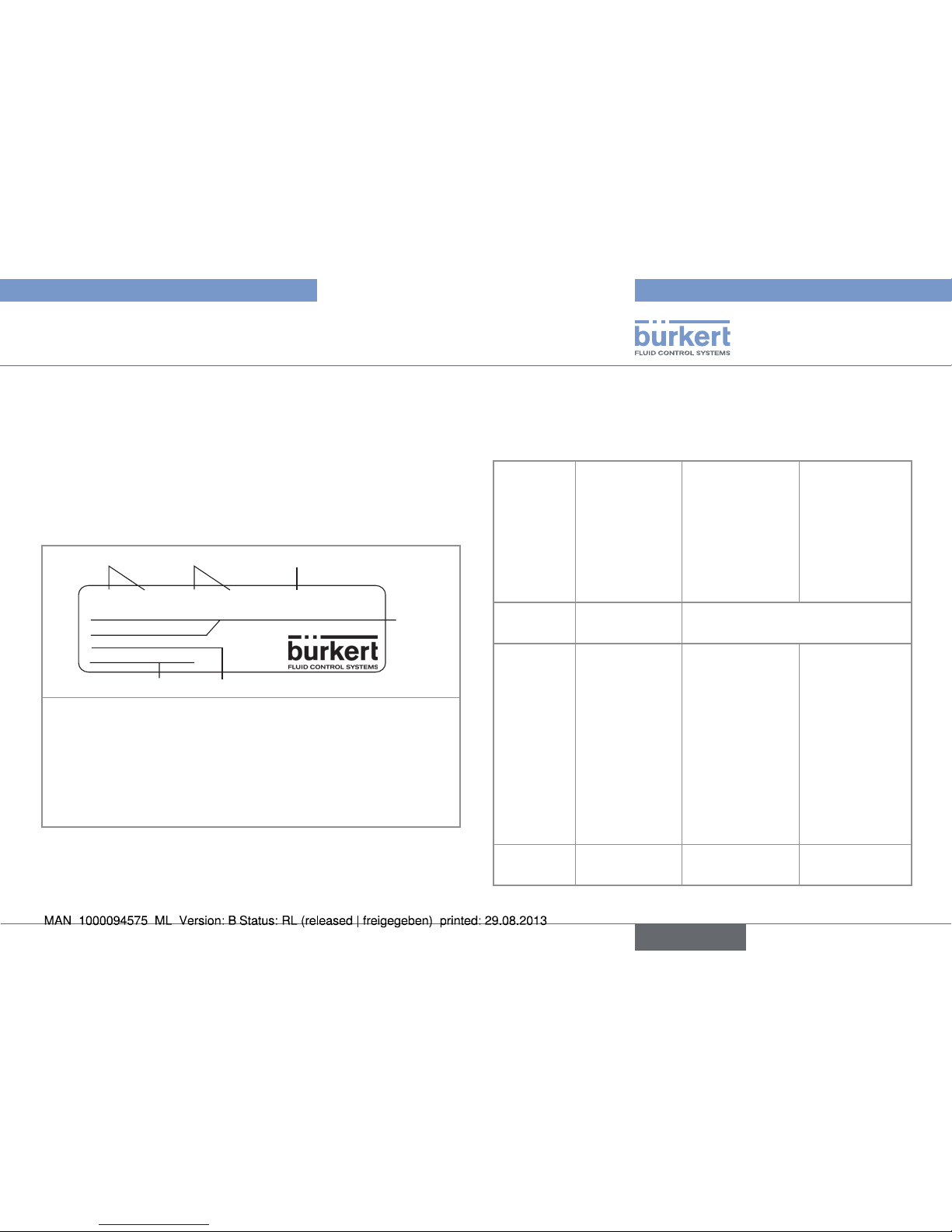
5.2. Description of the name plate
COND 8221 PEEK SST CLAMP
Conductivity probe
Leitfähigkeitssonde
ID No 00563269
WO: 2130329 / 033
1
2
4
3
56
1. Measured quantity and type of the probe
2. Material of the probe
3. Type of connection
4. Version of the probe
5. Order code
6. Construction code
Fig. 1: Name plate of the 8221
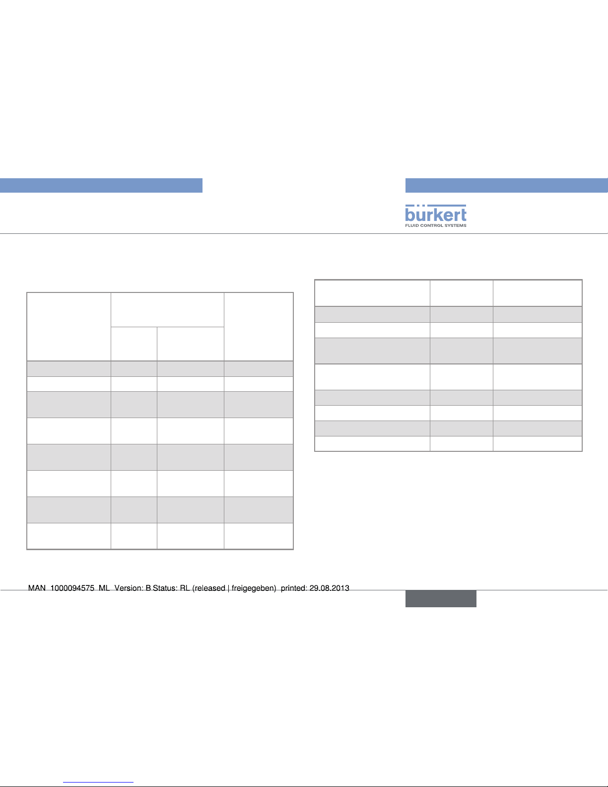
6. TECHNICAL DATA
6.1. Mechanical data
Process
connection
1.5" clamp • G1¼"
• 1.5" clamp,
short and
long
• 2" clamp
• 2" connection
DN50/40
PG13.5
Number of
electrodes
2 4
Materials
Electrodes Stainless steel Stainless steel
1.4435/316L
Stainless steel
1.4435/316L
Frame Stainless steel
PTFE
Stainless steel
1.4435/316L
PEEK with FDA
approval (CFR
177.2415)
PEEK with FDA
approval (CFR
177.2415)
Seal EPDM EPDM with FDA
approval
EPDM with FDA
approval
Surface
quality
0.4 µm,
electro-polished
0.4 µm,
electro-polished
0.4 µm,
electro-polished
* Adapted for GEA Tuchenhagen VARINLINE process connections
5
Description
Type 8221
English
Page 8
6.2. Certifications
Design according to EHEDG for:
• 8221 1.5" clamp connection short insertion depth;
• 8221 1.5" clamp connection long insertion depth;
• 8221 2" clamp connection.
Design approved by EHEDG for:
• 8221 2" (DN50/40) connection, adapted for GEA Tuchenhagen
VARINLINE process connections;
• 8221 PG13.5
6.3. General technical data
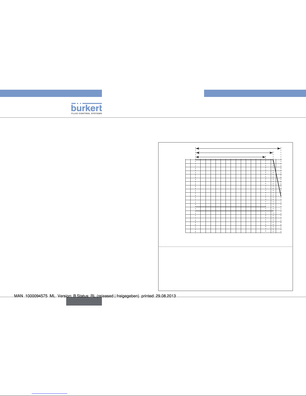
Tab. 1 : Temperature/pressure dependency diagram
16
15
14
13
12
11
10
9
8
7
6
5
4
3
2
1
0
-20 0 +20 +40 +60
+80 +100 +120
+140
20
19
18
17
A
B
C
Pressure:
[bar]
Temperature [°C]
Operating range for the conductivity probe:
A: with 2 electrodes, 1.5" clamp connection
B: with 4 électrodes, G1¼" and 1.5" clamp connections (short
and long insertion depth)
C: with 4 électrodes, 2" clamp, 2" (DN50/40) connection, adapted
for GEA Tuchenhagen VARINLINE process connections and
PG13.5 connections
6
Technical data
Type 8221
English
Page 9
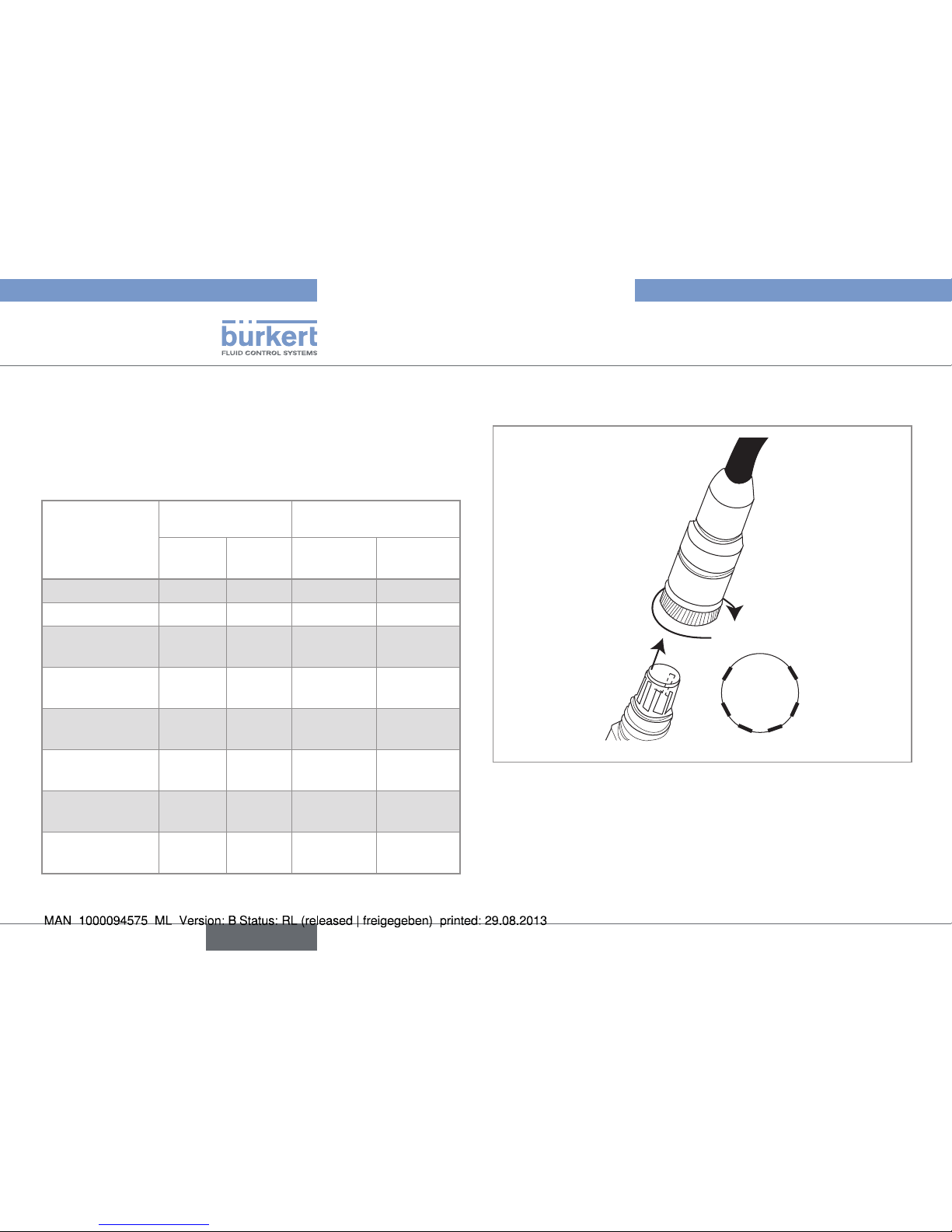
8221 with 2 electrodes, 1.5" clamp connection
Order code 564898 562261 564899
Measurement
range
0.05...20 µS/cm
-1)
1...200 µS/cm
-1)
5...5000 µS/cm
-1)
Linearity
1)
(relative)
±0.5... 5%
Cell
constant
2)
0.01 cm
-1
0.1 cm
-1
1 cm
-1
Max. fluid
temperature
120 °C
Fluid
pressure
7 bar max.
Temperature
sensor
Pt1000
Electrical
connection
Cable, length 3 m, instrument side with open wire.
1)
± 0.5% accuracy can be achieved when calibration is performed in
a conductivity range close to that of the process. With an extended
measuring range, the linearity is about 5%. The linearity also
depends on the device used.
2)
Value measured according to the Bürkert standard procedure. The
cell constant may be influenced by the mounting position.
8221 with 4 electrodes and G1¼"
connection
Order code 562240
Measurement range
0.1 µS/cm... 500 mS.cm
-1
Linearity
1)
(relative)
±0.5... 5%
Cell constant
2)
0.147 cm
-1
Max. fluid temperature
-20 to 135 °C. max
Fluid pressure
6 bar max.
Temperature sensor
Pt1000
Electrical connection
High temperature cable, length 5 m,
instrument side with open wire.
1)
± 0.5% accuracy can be achieved when calibration is performed in
a conductivity range close to that of the process. With an extended
measuring range, the linearity is about 5%. The linearity also
depends on the device used.
2)
Value measured according to the Bürkert standard procedure. The
cell constant may be influenced by the mounting position.
7
Technical data
Type 8221
English
Page 10
8221 with 4 electrodes and 1,5"
clamp connection
Short insertion depth
Order code 557719
Measurement range
0.1 µS/cm... 500 mS.cm
-1
Linearity
1)
(relative)
±0.5... 5%
Cell constant
2)
0.147 cm
-1
Max. fluid temperature
-20 to 135 °C. max
Fluid pressure
6 bar max.
Temperature sensor
Pt1000
Electrical connection
High temperature cable, length 5 m,
instrument side with open wire.
1)
± 0.5% accuracy can be achieved when calibration is performed in
a conductivity range close to that of the process. With an extended
measuring range, the linearity is about 5%. The linearity also
depends on the device used.
2)
Value measured according to the Bürkert standard procedure. The
cell constant may be influenced by the mounting position.
8221 with 4 electrodes and 1,5"
clamp connection
Long insertion depth
Order code 558884
Measurement range
0.1 µS/cm... 500 mS.cm
-1
Linearity
1)
(relative)
±0.5... 5%
Cell constant
2)
0.147 cm
-1
Max. fluid temperature
-20 to 135 °C. max
Fluid pressure
6 bar max.
Temperature sensor
Pt1000
Electrical connection
High temperature cable, length 5 m,
instrument side with open wire.
1)
± 0.5% accuracy can be achieved when calibration is performed in
a conductivity range close to that of the process. With an extended
measuring range, the linearity is about 5%. The linearity also
depends on the device used.
2)
Value measured according to the Bürkert standard procedure. The
cell constant may be influenced by the mounting position.
8
Technical data
Type 8221
English
Page 11
8221 with 4 electrodes and 2"
clamp connection
Order code 559120
Measurement range
1 µS/cm... 500 mS.cm
-1
Linearity
1)
(relative)
±0.5... 5%
Cell constant
2)
0.360 cm
-1
Max. fluid temperature
-20 to 150 °C. max
Fluid pressure
20 bar max. from -20 to 135 °C and
10 bar max. at 150 °C
Temperature sensor
Pt1000
Electrical connection
VarioPin (VP 6.0) male connector
1)
± 0.5% accuracy can be achieved when calibration is performed in
a conductivity range close to that of the process. With an extended
measuring range, the linearity is about 5%. The linearity also
depends on the device used.
2)
Value measured according to the Bürkert standard procedure. The
cell constant may be influenced by the mounting position.
8221 with 4 electrodes and 2"
(DN50/40) connection, adapted
for GEA Tuchenhagen VARINLINE
process connections
Order code
563269
Measurement range
1 µS/cm... 500 mS.cm
-1
Linearity
1)
(relative)
±0.5... 5%
Cell constant
2)
0.360 cm
-1
Max. fluid temperature
-20 to 150 °C. max
Fluid pressure
20 bar max. from -20 to 135 °C and
10 bar max. at 150 °C
Temperature sensor
Pt1000
Electrical connection
VarioPin (VP 6.0) male connector
1)
± 0.5% accuracy can be achieved when calibration is performed in
a conductivity range close to that of the process. With an extended
measuring range, the linearity is about 5%. The linearity also
depends on the device used.
2)
Value measured according to the Bürkert standard procedure. The
cell constant may be influenced by the mounting position.
9
Technical data
Type 8221
English
Page 12
8221 with 4 electrodes and PG13.5
connection
Order code 563186
Measurement range
1 µS/cm... 500 mS.cm
-1
Linearity
1)
(relative)
±0.5... 5%
Cell constant
2)
0.360 cm
-1
Max. fluid temperature
-20 to 150 °C. max
Fluid pressure
20 bar max. from -20 to 135 °C and
10 bar max. at 150 °C
Temperature sensor
Pt1000
Electrical connection
VarioPin (VP 6.0) male connector
1)
± 0.5% accuracy can be achieved when calibration is performed in
a conductivity range close to that of the process. With an extended
measuring range, the linearity is about 5%. The linearity also
depends on the device used.
2)
Value measured according to the Bürkert standard procedure. The
cell constant may be influenced by the mounting position.
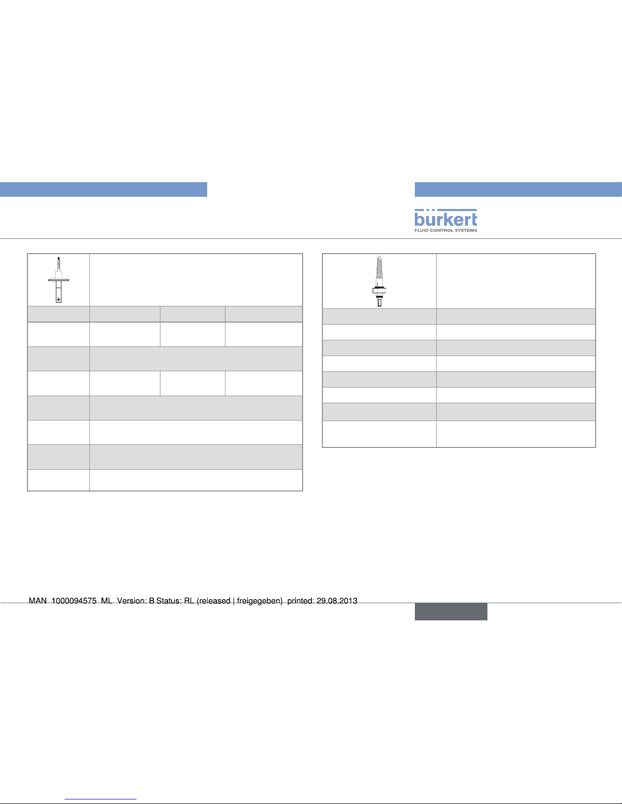
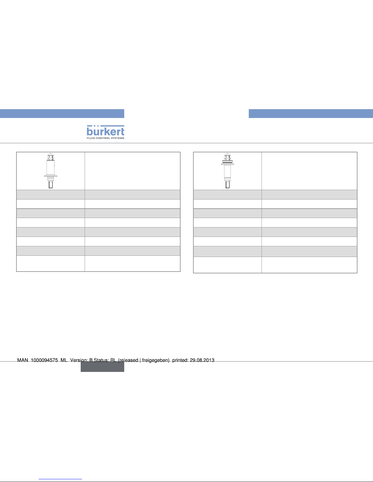
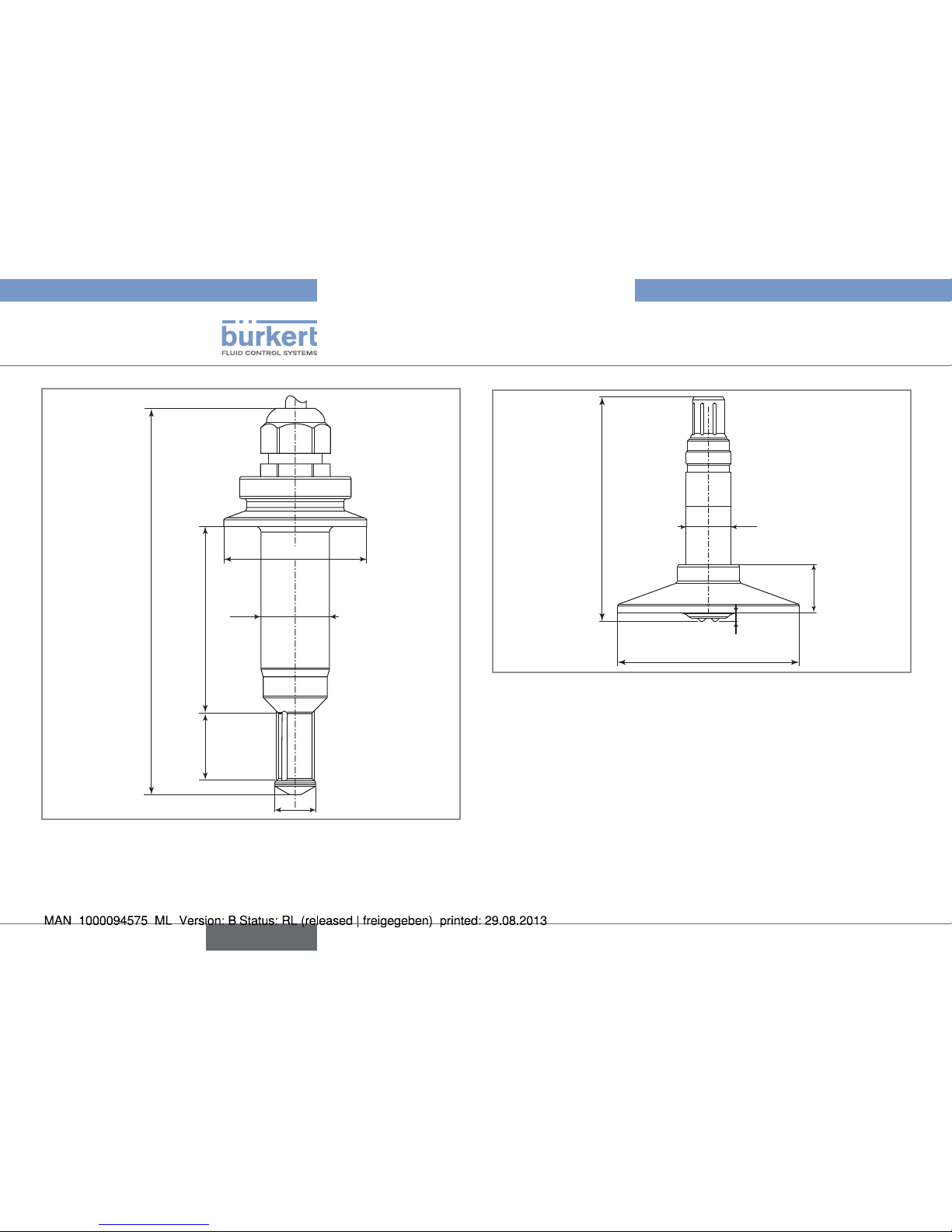
6.4. Dimensions
C
A
D
B
12.7
3 m
Order code Dimensions
A [mm]
Dimensions
B [mm]
Dimensions
C [mm]
Dimensions
D [mm]
564899 50.5 94 67 7.9
562261 50.5 94 67 7.9
564898 50.5 154 127 50
Fig. 2: Dimensions [mm] of a 8221 conductivity probe with 2
electrodes and 1,5" clamp connection
10
Technical data
Type 8221
English
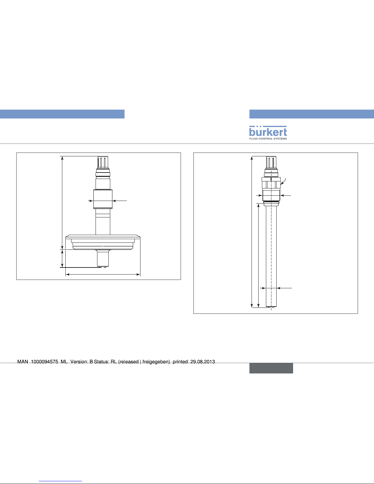
Page 13
24 OP =28 1
65 8
20
185
Ø 13
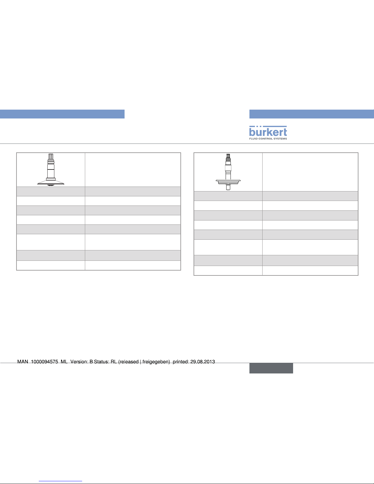
Fig. 3: Dimensions [mm] of a 8221 conductivity probe with 4
electrodes and G1¼" connection
ø13
ø24
ø50.5
ø30
24
50
141.5
21
Fig. 4: Dimensions [mm] of a 8221 conductivity probe with 4
electrodes and 1,5" clamp connection, short version
11
Technical data
Type 8221
English
Page 14
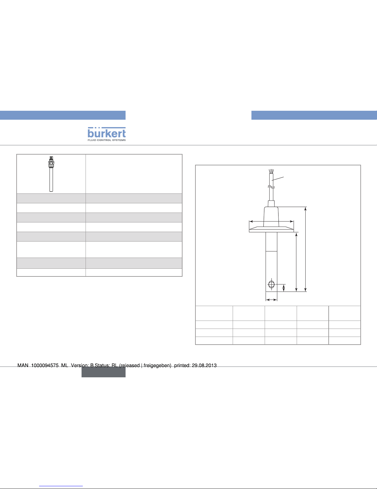
ø13
ø24
ø50.5
24 68
139.5
Fig. 5: Dimensions [mm] of a 8221 conductivity probe with 4
electrodes and 1,5" clamp connection, long version
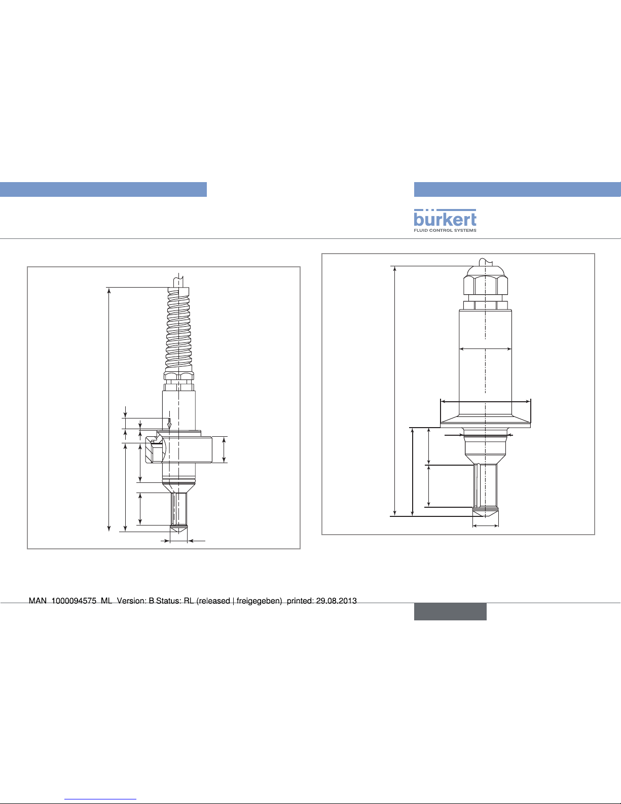
79
3
ø16
17
ø64
0
-0.2
Fig. 6: Dimensions [mm] of a 8221 conductivity probe with 4
electrodes and 2" clamp connection
12
Technical data
Type 8221
English
Page 15
Ø 21
10921
Fig. 7: Dimensions [mm] of a 8221 conductivity probe with 4
electrodes and 2" (DN50/40) connection, adapted for
GEA Tuchenhagen VARINLINE process connections
Ø 12
PG 13.5
174.5
120
AF19
Fig. 8: Dimensions [mm] of a 8221 conductivity probe with 4
electrodes and PG13.5 connection
13
Technical data
Type 8221
English
Page 16
7. INSTALLATION
7.1. Safety instructions
danger
Risk of injury due to high pressure in the installation.
• Stop the circulation of fluid, cut off the pressure and drain the
pipe before loosening the process connections.
Risk of injury due to electrical voltage.
• Shut down and isolate the electrical power source before carrying out work on the system.
• Observe all applicable accident protection and safety regulations for electrical equipment.
Risk of injury due to high fluid temperatures.
• Use safety gloves to handle the probe.
• Stop the circulation of fluid and drain the pipe before loosening
the process connections.
Risk of injury due to the nature of the fluid.
• Respect the regulations on accident prevention and safety relating to the use of aggressive fluids.
Warning
Risk of injury due to nonconforming installation.
• The electrical and fluid installation can only be carried out by
qualified and skilled staff with the appropriate tools.
• Respect the assembly instructions for the fitting and/or the
holder used.
Risk of injury due to unintentional switch on of power supply
or uncontrolled restarting of the installation.
• Avoid unintentional activation of the installation.
• Guarantee a set or controlled restarting of the process subsequent to any intervention.
7.2. Installation onto the pipe
danger
Risk of injury due to high pressure in the installation.
• Stop the circulation of fluid, cut off the pressure and drain the
pipe before loosening the process connections.
Risk of injury due to the nature of the fluid.
• Respect the regulations on accident prevention and safety relating to the use of aggressive fluids.
14
Installation
Type 8221
English
Page 17
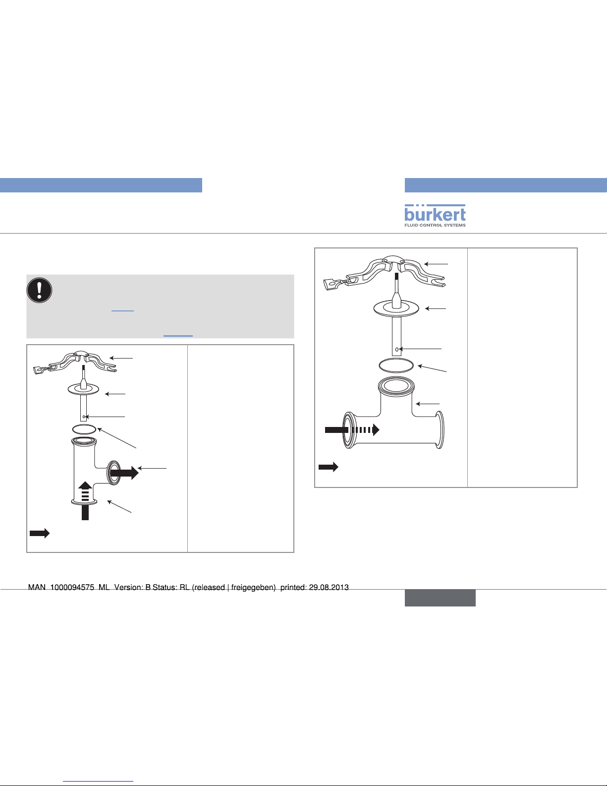
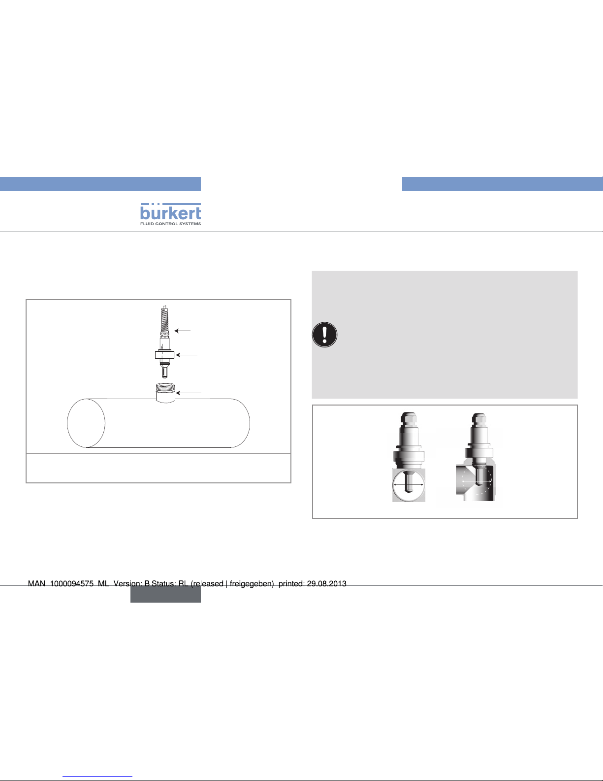
7.2.1. Installation of a 8221 with 2
electrodes
Avoid the formation of air bubbles around the probe.
→ For the order code 564898 carry out the mounting pro-
cedure on Fig. 9.
→ For the order code 564899 and 562261 carry out the
mounting procedure on Fig. 10.
1
2
4
6
3
5
Flow direction (indicated by the
arrows on the probe)
→ Put the seal 4 onto
the hygienic teefitting 6.
→ Put the probe 2 onto
the seal 4.
→ Align the hole 3 of
the probe with the
outlet 5 of the teefitting. The arrows on
the probe indicate
how to place the
probe.
→ Fix the clamp of the
probe 2 and the
clamp of the fitting
with the flange clamp
1.
Fig. 9: Installation of a 8221 with 2 electrodes and with order
code 564898
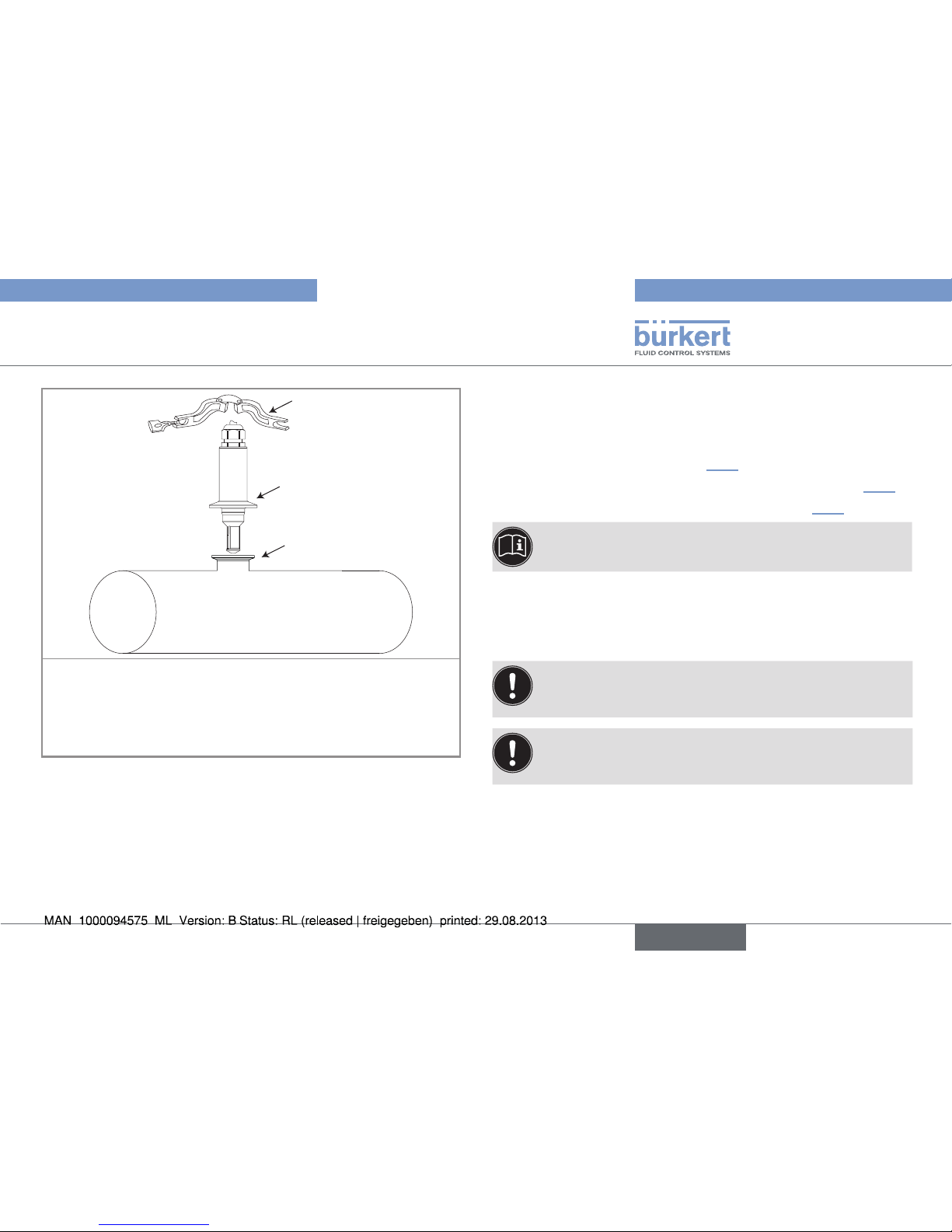
1
2
4
3
5
Flow direction (indicated by the
arrows on the probe)
→ Put the seal 4 onto
the hygienic tee-fitting
5.
→ Put the probe 2 onto
the seal 4.
→ Align the hole 3 of the
probe with the flow
direction. The arrows
on the probe indicate
how to place the
probe.
→ Fix the clamp of the
probe 2 and the
clamp of the fitting
with the flange clamp
1.
Fig. 10: Installation of a 8221 with 2 electrodes and with order
code 564899 or 562261
15
Installation
Type 8221
English
Page 18
→ Make sure you follow the recommendations below when con-
necting the conductivity probe.
The cell constant and the linearity of the probe may vary
depending on the mounting position. A symmetrical setup is
recommended:
• Leave a clearance of 60mm minimum diameter around the
probe.
• Connection pieces made of non-conductive material
should preferably be used.
To achieve high precision the cell constant should be calibrated in the final setup:
• Make sure that all 4 electrodes are completely and continuously immersed in the measuring sample.
A: ø 60 mm min
A
A
Fig. 12: Placing the probe onto the pipe
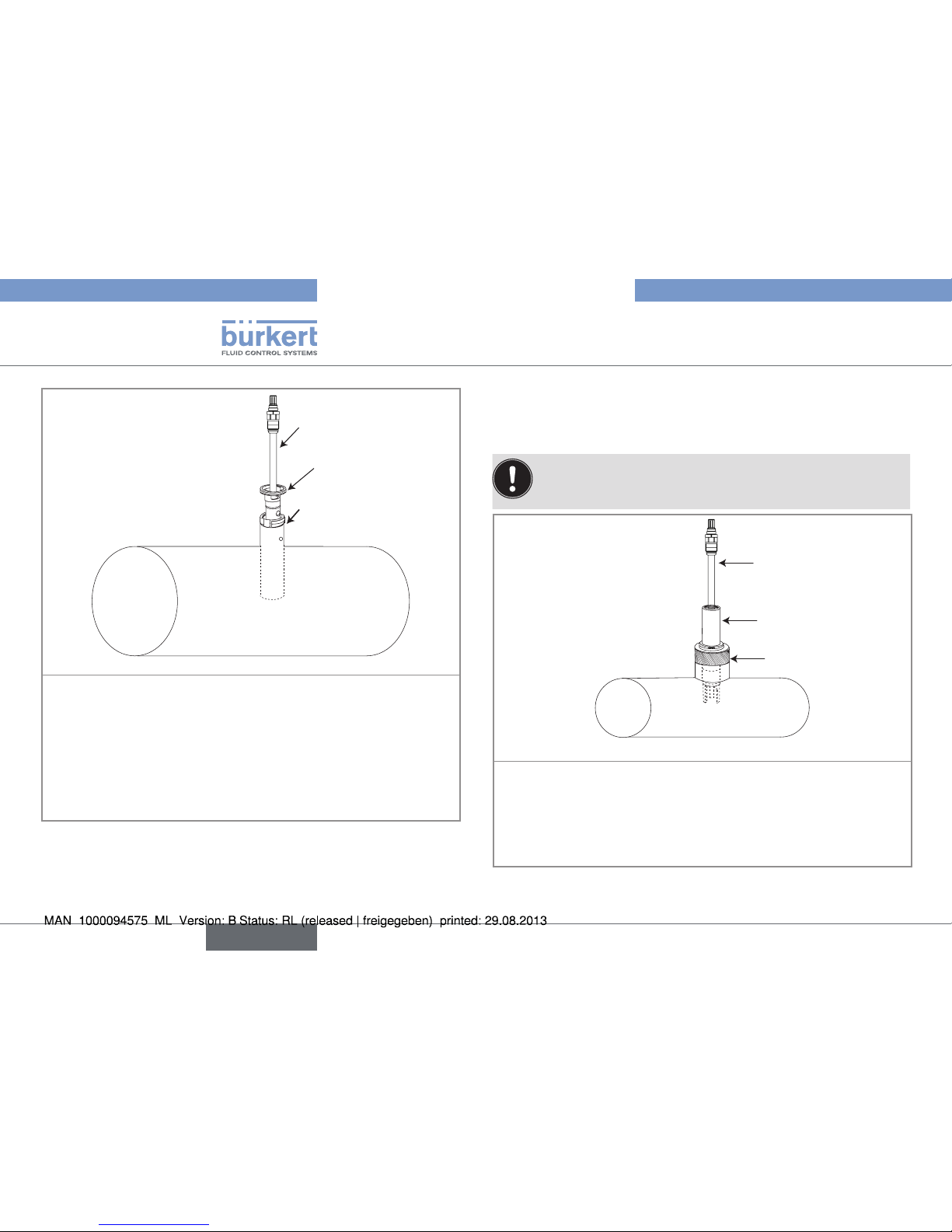
7.2.2. Installation of a 8221 with G1¼"
connection
The 8221 probe is screwed onto a 1¼" weld-in socket, with order
code 737241, fixed onto the pipe.
1
3
2
→ Insert the probe 1 inside the socket 3.
→ Screw the nut 2 onto the socket 3.
Fig. 11: Installation of a 8221 G1¼" connection
7.2.3. Installation of a 8221 with clamp
connection
→ Make sure that the process connection is clean.
→ Clean it if necessary.
16
Installation
Type 8221
English
Page 19
3
2
1
→ Check that the seal is on the probe.
→ Install the 8221 with clamp connection 2 onto the clamp of the
pipe 1.
→ Place the clamp together.
→ Fix the clamps with the flange clamp 3.
Fig. 13: Installation of a 8221 clamp connection
7.2.4. Installation of a 8221 with 2"
(DN50/40) connection
The 8221 probe with 2" (DN50/40) connection is mounted onto the
GEA Tuchenhagen VARINLINE process connections to the appropriate dimensions.
7.2.5. Installation of a 8221 with PG13.5
connection
The probe 8221 with PG13.5 connection is mounted onto a holder:
• 8200 direct welding holder (see 7.2.6);
• 8200 hygienic holder with G1¼" threaded connection (see 7.2.7);
• 8200 hygienic holder with clamp connection (see 7.2.8).
To install the holder, refer to the 8200 direct welding holder
and to the 8200 hygienic holder using manuals.
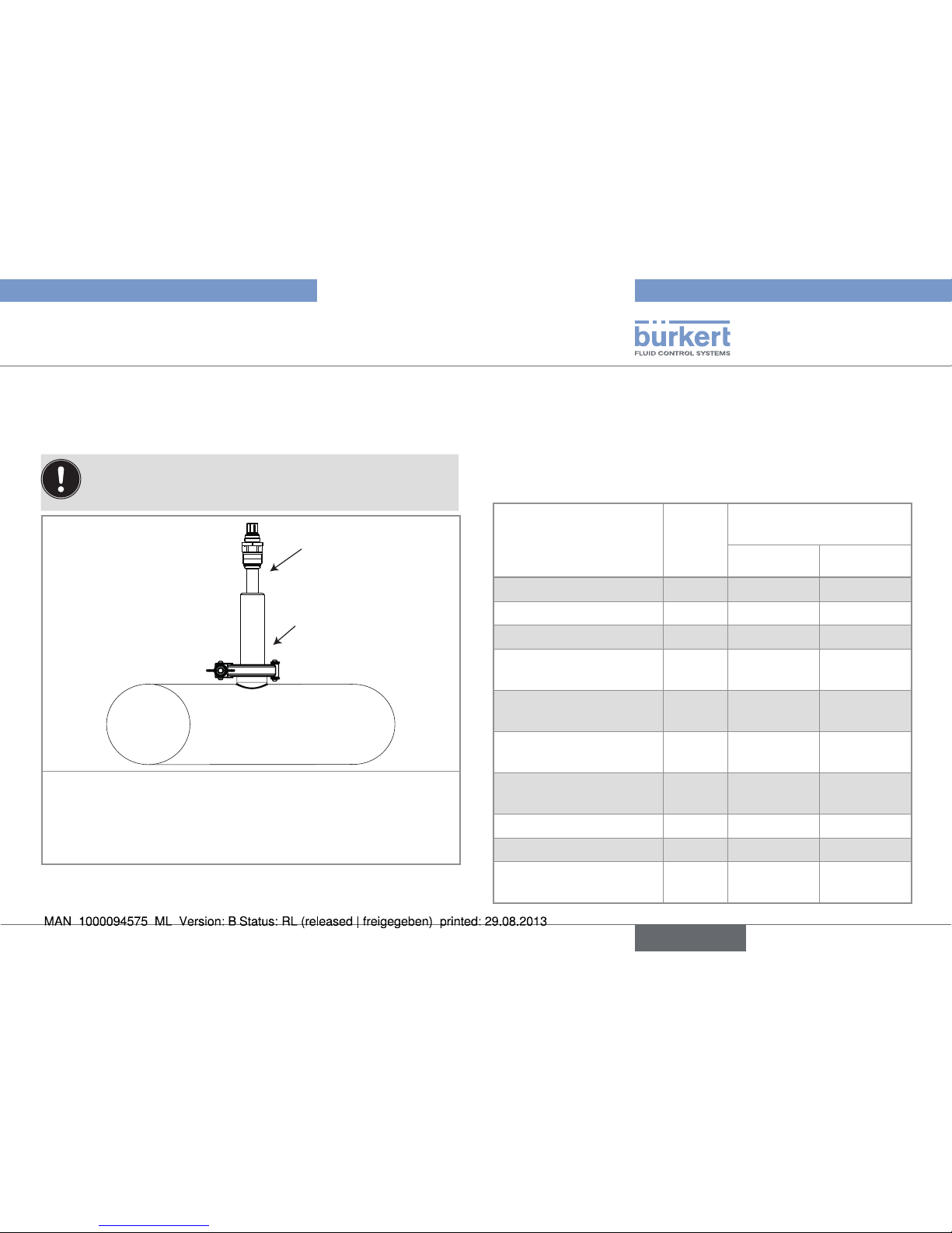
7.2.6. Installation of a 8221 with PG13.5
connection onto a direct welding
holder
The holder is intended only for mounting probes with a
length of 120 mm.
Make sure the welded area has cooled down before
inserting the probe.
17
Installation
Type 8221
English
Page 20
1
2
3
→ Make sure the direct welding holder is mounted onto the pipe.
→ Ensure there is no damage to the probe or the holder.
→ Check that all O-rings are in place in their appropriate
grooves, and are free of damage.
→ Insert the seal pusher 2 into the holder 3.
→ Screw the probe 1 into the seal pusher 2 using a locking
torque between 2 and 3 Nm.
Fig. 14: Installation of a 8221 with PG13.5 connection onto a
direct welding holder
7.2.7. Installation of a 8221 with PG13.5
connection onto a G1¼" threaded
hygienic holder
• To avoid any mechanical damage to O-rings on assembly,
they should be lightly greased.
• After assembly, clean the probe of any remaining drops of grease.
1
2
3
→ Ensure there is no damage to the probe or the holder.
→ Check that all O-rings are in place in their appropriate grooves,
and are free of damage.
→ Make sure the holder 2 is mounted onto an adaptor 3 welded
onto the pipe.
→ Screw the probe 1 in the holder 2.
Fig. 15: Installation of a 8221 with PG13.5 connection onto a
holder with G1¼" connection
18
Installation
Type 8221
English
Page 21
7.2.8. Installation of a 8221 with PG13.5
connection onto a hygienic holder
with clamp connection
• To avoid any mechanical damage to O-rings on assembly,
they should be lightly greased.
• After assembly, clean the probe of any remaining drops of grease.
1
2
→ Ensure there is no damage to the probe or the holder.
→ Check that all o-rings are in place in their appropriate grooves,
and are free of damage.
→ Make sure the holder 2 is fixed onto the clamp of the pipe.
→ Screw the probe 1 in the holder 2
Fig. 16: Installation of a 8221 with PG13.5 connection onto a
holder with clamp connection
8. WIRING
8.1. Wiring of the 8221 with 4
electrodes, with 1.5" clamp (short
and long) or G1¼" connections
Signal description
Cable
color
Bürkert device connected
Type 8285 Type 8619
Pt1000 (low end) grey 18 7 SE
Pt1000 white 19 8 TS
Pt1000 blue 17 9 TS
Current electrode (high
end)
pink 1 1 C+
Potential electrode (high
end)
green 2 2 P+
Potential electrode (low
end)
brown 3 3 P-
Current electrode (low
end)
yellow 4 4 C-
Not connected on probe shield 16 6 FE
Not connected red - -
Note: -
short 4 and
5
-
19
Wiring
Type 8221
English
Page 22
8.2. Wiring of the 8221 with 4
electrodes, with 2" clamp or 2"
(DN50/40) connection, adapted
for GEA Tuchenhagen VARINLINE
process connections
Signal
description
VarioPin * Bürkert device connected
Pin
Cable
color
Type 8285 Type 8619
Pt1000 E white 17 9 TS
Pt1000 F green 18 7 SE
Current elec-
trode (high end)
B red 1 1 C+
Potential electrode (high end)
A
trans-
parent
2 2 P+
Potential electrode (low end)
C grey 3 3 P-
Current electrode (low end)
D blue 4 4 C-
Not connected
on probe
shield
green/
yellow
16 6 FE
Note: - -
short 18
and 19
short 7 SE
and 8 TS
*The cable colors are only valid for the Bürkert Vario Pin connection cables
with order code: 554855, 554856, 554857.
A
D
F
E
B
C
Fig. 17: View of the pin of the 8221 probe
20
Wiring
Type 8221
English
Page 23
8.3. Wiring of the 8221 with 4
electrodes, with PG13.5
connection
Signal description
VarioPin *
Bürkert
type 8619
transmitter
Pin Cable color
Pt1000 E white 9 TS
Pt1000 F green 7 SE
Current electrode
(high end)
B red 1 C+
Potential electrode
(high end)
A transparent 2 P+
Potential electrode
(low end)
C grey 3 P-
Current electrode
(low end)
D blue 4 C-
Not connected on
probe
shield green/yellow 6 FE
Note: - -
short 7 SE and
8 TS
*The cable colors are only valid for the Bürkert Vario Pin connection cables
with order code: 554855, 554856, 554857.
8.4. Wiring of a 8221 with 2
electrodes
Signal description Cable color Bürkert type 8619
transmitter
Pt1000 red 9 TS
Pt1000 green 7 SE
Potential electrode (low
end)
white 3 P-
Potential electrode (high
end)
black 2 P+
Shield transparent 6 FE
Note: - short 7 SE and 8 TS
Note: - short 2 P+ et 1 C+
Note: - short 3 P- and 4 C-
21
Wiring
Type 8221
English
Page 24

9. CALIBRATION
There are two possibilities for calibration:
• calibration while the probe is disassembled from process ;
• calibration in the process.
9.1. Calibration while the probe is
disassembled from process
→ Rinse the probe thoroughly with deionized water.
→ Use a beaker with an internal diameter of at least 60mm. (The
probe can be directly immersed into the Bürkert conductivity
standard calibration solutions).
→ Use a solution of known conductivity.
→ Check the temperature dependency.
→ Immerse the probe in the calibration solution. Make sure that the
4 electrodes are immersed. The probe should be placed in the
center of the beaker.
→ Leave the probe for at least 5 minutes for equilibration, before
initiating the calibration on the instrument.
For precise determination of the cell constant, it is recommended
that you use an assembly situation similar to the situation in the
process. The cell constant may vary according to the final mounting
position of the process.
9.2. Calibration in the process
→ Insert the probe in the process.
→ Leave conductivity and temperature at least 15 min. for
equilibration.
→ Take a process sample and perform an external measurement
with a reference conductivity system. The best approach is to
perform the measurement at a temperature equal to that of the
process. If that is not possible, you need to know the temperature coefficient of your sample.
→ Manually adjust the cell constant to read the same conductivity
value on the process instrument.
You may switch off the temperature compensation of
the process to prevent any errors. Refer to the operating
instructions of the device connected to the probe.
22
CALIBRATION
Type 8221
English
Page 25
10. MAINTENANCE AND
TROUBLESHOOTING
10.1. Safety instructions
danger
Risk of injury due to high pressure in the installation.
• Stop the circulation of fluid, cut off the pressure and drain the
pipe before loosening the process connections.
Risk of injury due to electrical voltage.
• Shut down the electrical power source of all the conductors and
isolate it before carrying out work on the system.
• Observe all applicable accident protection and safety regulations for electrical equipment.
Risk of injury due to high fluid temperatures.
• Use safety gloves to handle the probe.
• Stop the circulation of fluid and drain the pipe before loosening
the process connections.
Risk of injury due to the nature of the fluid.
• Respect the prevailing regulations on accident prevention and
safety relating to the use of aggressive fluids.
Warning
Risk of injury due to non-conforming maintenance.
• Maintenance must only be carried out by qualified and skilled
staff with the appropriate tools.
• Ensure that the restart of the installation is controlled after any
interventions.
10.2. Maintenance of the probe
The probe can be cleaned with a cloth dampened with water or a
detergent compatible with the materials the probe is made of.
Please feel free to contact your Bürkert supplier for any additional
information.
Check the O-rings regularly.
23
Maintenance and troubleshooting
Type 8221
English
Page 26

11. SPARE PARTS AND
ACCESSORIES
attention
Risk of injury and/or damage caused by the use of unsuitable
parts.
Incorrect accessories and unsuitable replacement parts may
cause injuries and damage the device and the surrounding area.
• Use only original accessories and original replacement parts
from Bürkert.
Accessories Order code
Calibration solution, 5 µS/cm conductivity
standard, ± 1% accuracy, 300 ml
440015
Calibration solution, 15 µS/cm conductivity
standard, ± 5% accuracy, 300 ml
440016
Calibration solution, 100 µS/cm conductivity
standard, ± 3% accuracy, 300 ml
440017
Calibration solution, 706 µS/cm conductivity
standard, ± 2% accuracy, 300 ml
440018
Calibration solution, 1413 µS/cm conductivity
standard, ± 1% accuracy, 300 ml
440019
Calibration solution, 100 µS/cm conductivity
standard, ± 1% accuracy, 300 ml
440020
Connection cable VarioPin (VP 6.0), female
connector, 3 meters
554855
Accessories Order code
Connection cable VarioPin (VP 6.0), female
connector, 5 meters
554856
Connection cable VarioPin (VP 6.0), female
connector, 10 meters
554857
12. PACKAGING, TRANSPORT
note
Damage due to transport
Transport may damage an insufficiently protected part.
• Transport the probe in shock-resistant packaging and away from
humidity and dirt.
• Do not expose the probe to temperatures that may exceed the
admissible storage temperature range.
24
Spare parts and accessories
Type 8221
English
Page 27

13. STORAGE
note
Poor storage can damage the probe.
• Store the probe in a dry place away from dust.
14. DISPOSAL OF THE PROBE
→
Dispose of the device and its packaging in an environmentallyfriendly way.
note
Damage to the environment caused by products contaminated by fluids.
• Keep to the existing provisions on the subject of waste disposal
and environmental protection.
Note:
Comply with the national and/or local regulations which
concern the area of waste disposal.
25
Spare parts and accessories
Type 8221
English
Page 28

26
Type 8221
English
Page 29

1
Typ 8221
1. DIE BEDIENUNGSANLEITUNG ...............................................................2
1.1. Darstellungsmittel ....................................................................... 2
1.2. Begriffsdefinition "Sonde" ........................................................2
2. BESTIMMUNGSGEMÄSSE VERWENDUNG ......................................3
3. GRUNDLEGENDE SICHERHEITSHINWEISE ....................................3
4. ALLGEMEINE HINWEISE .............................................................................5
4.1. Kontaktadressen ........................................................................ 5
4.2. Gewährleistung ........................................................................... 5
4.3. Informationen im Internet...........................................................5
5. BESCHREIBUNG .............................................................................................5
5.1. Vorgesehener Einsatzbereich .................................................. 5
5.2. Beschreibung des Typenschilds .............................................5
6. TECHNISCHE DATEN ...................................................................................6
6.1. Mechanische Daten ...................................................................6
6.2. Zertifizierungen ............................................................................6
6.3. Allgemeine Daten........................................................................7
6.4. Maße ............................................................................................11
7. INSTALLATION ............................................................................................... 14
7.1. Sicherheitshinweise .................................................................14
7.2. Fluidischer Anschluss ..............................................................15
7.2.1. Verkabelung des 8221 mit 2 Elektroden .......................15
7.2.2. Installation eines 8221 mit Anschluss G1¼" ...............16
7.2.3. Installation eines 8221 mit Clamp-Anschluss ..............16
7.2.4. Installation eines 8221 mit Anschluss 2" DN50/40 ...17
7.2.5. Installation eines 8221 mit Anschluss PG13.5 ............18
7.2.6. Installation eines 8221 mit Anschluss PG13.5
auf einen Halter für direkte Anschweißung ...................18
7.2.7. Installation eines 8221 mit Anschluss PG13.5 auf
einen hygienischen Halter mit G1¼''-Innengewinde ........19
7.2.8. Installation eines 8221 mit Anschluss PG13.5 auf
einen hygienischen Halter mit Clamp-Anschluss ...............19
8. ELEKTRISCHER ANSCHLUSS .............................................................. 20
8.1. Verkabelung der 8221 mit 4 Elektroden, mit Clamp-
Anschluss 1.5" (kurz oder lang) oder Anschluss G1¼" ............20
8.2. Verkabelung der 8221 mit 4 Elektroden, mit ClampAnschluss 2'' oder Anschluss 2" passend für GEA
Tuchenhagen VARINLINE Prozessanschluss.....................20
8.3. Vekabelung des 8221 mit 4 Elektroden, mit
Anschluss PG13.5 ...................................................................21
8.4. Verkabelung des 8221 mit 2 Elektroden.............................22
9. KALIBRIERUNG ............................................................................................. 22
9.1. Kalibrierung außerhalb des Prozesses ................................22
9.2. Kalibrierung im Prozess ...........................................................23
10. WARTUNG, FEHLERBEHEBUNG.......................................................23
10.1. Sicherheitshinweise .................................................................23
10.2. Reinigung der Sonde ...............................................................24
11. ERSATZTEILE UND ZUBEHÖR...........................................................24
12. VERPACKUNG, TRANSPORT ..............................................................25
13. LAGERUNG ................................................................................................... 25
14. ENTSORGUNG DER SONDE ...............................................................25
deutsch
Page 30

2
Die Bedienungsanleitung
Typ 8221
1. DIE BEDIENUNGSANLEITUNG
Die Bedienungsanleitung beschreibt den gesamten Lebenszyklus
der Sonde. Bewahren Sie diese Anleitung so auf, dass sie für jeden
Benutzer zugänglich ist und jedem neuen Eigentümer des Gerätes
wieder zur Verfügung steht.
Diese Bedienungsanleitung enthält wichtige Informationen
zur Sicherheit!
Das Nichtbeachten dieser Hinweise kann zu gefährlichen Situationen führen.
• Diese Bedienungsanleitung muss gelesen und verstanden
werden.
1.1. Darstellungsmittel
Gefahr!
Warnt vor einer unmittelbaren Gefahr!
• Bei Nichteinhaltung sind Tod oder schwere Verletzungen die
Folge.
WarnunG!
Warnt vor einer möglicherweise gefährlichen Situation!
• Bei Nichteinhaltung drohen schwere Verletzungen oder Tod.
VOrSIChT!
Warnt vor einer möglichen Gefährdung!
• Nichtbeachtung kann mittelschwere Verletzungen oder leichte
Verletzungen zu Folge haben.
hInWeIS!
Warnt vor Sachschäden!
• Bei Nichtbeachtung kann die Sonde oder die Anlage beschädigt werden.
bezeichnet wichtige Zusatzinformationen, Tipps und
Empfehlungen.
verweist auf Informationen in dieser Bedienungsanleitung
oder in anderen Dokumentationen.
→ markiert einen Arbeitsschritt, den Sie ausführen müssen.
1.2. Begriffsdefinition "Sonde"
Der in dieser Anleitung verwendete Begriff "Sonde" steht immer für
die Leitfähigkeitssonde Typ 8221.
deutsch
Page 31

3
Bestimmungsgemässe Verwendung
Typ 8221
2. BESTIMMUNGSGEMÄSSE
VERWENDUNG
Bei nicht bestimmungsgemäßem Einsatz dieser Sonde
können Gefahren für Personen, Anlagen in der Umgebung
und die Umwelt entstehen.
• Die Leitfähigkeitssonde Typ 8221 dient zur Messung der elektrischen Leitfähigkeit in Lösungen.
• Für den Einsatz sind die in den Vertragsdokumenten und der
Bedienungsanleitung spezifizierten zulässigen Daten, Betriebsund Einsatzbedingungen zu beachten.
• Zum sicheren und problemlosen Einsatz der Sonde müssen
Transport, Lagerung und Installation ordnungsgemäß erfolgen,
außerdem müssen Betrieb und Wartung sorgfältig durchgeführt
werden.
• Achten Sie immer darauf, diese Sonde auf ordnungsgemäße
Weise zu verwenden.
→ Beachten Sie bei der Ausfuhr der Sonde gegebenenfalls beste-
hende Beschränkungen.
3. GRUNDLEGENDE
SICHERHEITSHINWEISE
Diese Sicherheitshinweise berücksichtigen keine:
• Zufälligkeiten und Ereignisse, die bei Montage, Betrieb und
Wartung der Geräte auftreten können.
• Ortsbezogenen Sicherheitsbestimmungen, für deren Einhaltung,
auch in Bezug auf das Installations- und Wartungspersonal, der
Betreiber verantwortlich ist.
Gefahr durch hohen Druck in der Anlage!
• Vor dem Lösen der Prozessanschlüsse die Anlage druckfrei
schalten und die Flüssigkeitszirkulation stoppen.
Gefahr durch elektrische Spannung!
• Schalten Sie vor Beginn der Arbeiten in jedem Fall alle existierenden am Gerät angeschlossenen Spannungs-Versorgungen ab,
und sichern Sie diese vor unbeabsichtigtem Wiedereinschalten!
• Beachten Sie geltende Unfallverhütungs- und Sicherheitsbestimmungen für elektrische Geräte!
Gefahr durch hohe Flüssigkeitstemperaturen!
• Die Sonde nur mit Schutzhandschuhen anfassen.
• Vor dem Lösen der Prozessanschlüsse die Flüssigkeitszirkulation stoppen und die Rohrleitung leer laufen lassen.
deutsch
Page 32

4
Grundlegende Sicherheitshinweise
Typ 8221
Gefahr aufgrund der Art der Flüssigkeit!
• Beachten Sie die Regeln, die auf dem Gebiet der Unfallverhütung und der Sicherheit in Kraft sind und die sich auf die
Verwendung gefährlicher Produkte beziehen.
Allgemeine Gefahrensituationen.
Zum Schutz vor Verletzungen ist zu beachten:
• Diese Sonde nicht in explosionsgefährdeten Bereichen
einsetzen.
• Diese Sonde nicht in einer Umgebung verwenden, die mit den
Materialien, aus denen es besteht, inkompatibel ist.
• Keine Flüssigkeit verwenden, die sich nicht mit den Werkstoffen
verträgt, aus denen die Sonde besteht.
• Installations- und Instandhaltungsarbeiten dürfen nur von autorisiertem Fachpersonal mit geeignetem Werkzeug ausgeführt
werden.
• Betreiben Sie die Sonde nur in einwandfreiem Zustand und
unter Beachtung der Bedienungsanleitung.
• Bei der Einsatzplanung und dem Betrieb der Sonde die allgemeinen Regeln der Technik einhalten.
hInWeIS!
Die Sonde kann durch das Medium beschädigt werden.
• Kontrollieren Sie systematisch die chemische Verträglichkeit
der Werkstoffe, aus denen die Sonde besteht, und der Flüssigkeiten, die mit dieser in Berührung kommen können (zum
Beispiel: Alkohole, starke oder konzentrierte Säuren, Aldehyde,
Basen, Ester, aliphatische Verbindungen, Ketone, aromatische
oder halogenierte Kohlenwasserstoffe, Oxidations- und chlorhaltige Mittel).
deutsch
Page 33

5
Allgemeine hinweise
Typ 8221
4. ALLGEMEINE HINWEISE
4.1. Kontaktadressen
Die internationale Kontaktadressen finden Sie im Internet unter:
www.burkert.com
4.2. Gewährleistung
Voraussetzung für die Gewährleistung ist der bestimmungsgemäße
Gebrauch der Sonde Typ 8221 unter Beachtung der im vorliegenden Handbuch spezifizierten Einsatzbedingungen.
4.3. Informationen im Internet
Bedienungsanleitungen und Datenblätter zum Typ 8221 finden Sie
im Internet unter: www.buerkert.de
5. BESCHREIBUNG
5.1. Vorgesehener Einsatzbereich
Die Leitfähigkeitssonde Typ 8221 dient zur Messung der elektrischen Leitfähigkeit in Lösungen.
5.2. Beschreibung des Typenschilds
COND 8221 PEEK SST CLAMP
Conductivity probe
Leitfähigkeitssonde
ID No 00563269
WO: 2130329 / 033
1
2
4
3
56
1. Messgröße und Typ der Sonde
2. Werkstoffe der Sonde
3. Anschluss-Typ
4. Ausführung der Sonde
5. Bestellnummer
6. Konstruktionscode
Bild 1: Typenschild des Typs 8221
deutsch
Page 34

6
Technische Daten
Typ 8221
6. TECHNISCHE DATEN
6.1. Mechanische Daten
Anschluss Clamp 1.5" • G1¼”
• Clamp 1.5", kurz
oder lang
• Clamp 2"
• 2" (DN50/40) *
PG13.5
ElekrodenAnzahl
2
4
Werkstoffe
Elektroden Edelstahl Edelstahl 1.4435/316L Edelstahl
1.4435/316L
Gehäuse Edelstahl
PTFE
Edelstahl 1.4435/316L
PEEK mit FDA-
Zulassung (CFR
177.2415)
PEEK mit FDAZulassung
(CFR
177.2415)
Dichtung EPDM EPDM mit
FDA-Zulassung
EPDM mit
FDA-Zulassung
Oberflächengüte
0.4 µm,
elektropoliert
0.4 µm, elektropoliert 0.4 µm,
elektropoliert
* passend für GEA Tuchenhagen VARINLINE Prozessanschluss
6.2. Zertifizierungen
Design gemäß den EHEDG-Kriterien für:
• 8221 mit Clamp-Anschluss 1.5" und kurzer Eintauchtiefe;
• 8221 mit Clamp-Anschluss 1.5" und langer Eintauchtiefe;
• 8221 mit Clamp-Anschluss 2".
Design mit EHEDG-Zertifizierung für:
• 8221 Anschluss 2" (DN50/40) passend für GEA Tuchenhagen
VARINLINE Prozessanschluss;
• 8221 mit Anschluss PG13.5
deutsch
Page 35

7
Technische Daten
Typ 8221
6.3. Allgemeine Daten
Tab. 1: Flüssigkeits-Druck-/Temperaturdiagramm
16
15
14
13
12
11
10
9
8
7
6
5
4
3
2
1
0
-20 0 +20 +40 +60
+80 +100 +120
+140
20
19
18
17
A
B
C
Druck
[bar]
Temperatur [°C]
Verwendungsbereich der Leitfähigkeitsonden:
A: mit 2 Elektroden, Clamp-Anschluss 1.5"
B: mit 4 Elektroden, Anschluss G1¼" oder Clamp 1.5" (kurze oder
lange Eintauchtiefe)
C: mit 4 Elektroden, Anschluss Clamp 2", Anschluss 2"
(DN50/40) passend für GEA Tuchenhagen VARINLINE Prozessanschluss und Anschluss PG13.5
8221 mit 2 Elektroden, Clamp-Anschluss 1.5"
Bestellnummer
564898 562261 564899
Messbereich 0.05... 20 µS.cm
-1
1... 200 µS.cm-15... 5000 µSc.cm-1
Linearität
1)
(relative)
±0.5... 5%
Zellkonstante
2)
0.01 cm
-1
0.1 cm
-1
1 cm
-1
Flüssigkeitstemperatur
max. 120 °C
Max. Druck
der Flüssigkeit
max. 7 bar
Temperaturfühler
Pt1000
Elektrischer
Anschluss
3-Meter langes Kabel, abisolierte elektrische Leitungen auf Seite des angeschlossenen Gerätes.
1)
Eine Genauigkeit von ± 0.5% wird erzielt, wenn die Kalibrierung
der Zellkonstante mit einer Kalibrierlösung deren Leitfähigkeit sich
der Leitfähigkeit der Prozesslösung nähert. Bei erweitertem Messbereich erreicht die Linearität 5%. Die Linearität hängt auch vom
verwendeten Gerät ab.
2)
Messwert mit Bürkert Standard-Verfahren. Die Zellkonstante kann
durch die Einbaulage geändert werden.
deutsch
Page 36

8
Technische Daten
Typ 8221
8221 mit 4 Elektroden, Anschluss
G1¼"
Bestellnummer
562240
Messbereich 0.1 µS/cm... 500 mS.cm
-1
Linearität
1)
(relative) ±0.5... 5%
Zellkonstante
2)
0.147 cm
-1
Flüssigkeitstemperatur -20 bis 135 °C
Max. Druck der Flüssigkeit max. 6 bar
Temperaturfühler Pt1000
Elektrischer Anschluss
Hochtemperatur-Kabel, 5 m-lang,
abisolierte elektrische Leitungen auf
Seite des angeschlossenen Gerätes.
1)
Eine Genauigkeit von ± 0.5% wird erzielt, wenn die Kalibrierung
der Zellkonstante mit einer Kalibrierlösung deren Leitfähigkeit sich
der Leitfähigkeit der Prozesslösung nähert. Bei erweitertem Messbereich erreicht die Linearität ± 5%. Die Linearität hängt auch vom
verwendeten Gerät ab.
2)
Messwert mit Bürkert Standard-Verfahren. Die Zellkonstante kann
durch die Einbaulage geändert werden.
8221 mit 4 Elektroden, ClampAnschluss 1.5"
Kurze Eintauchtiefe
Bestellnummer
557719
Messbereich 0.1 µS/cm... 500 mS.cm
-1
Linearität 1) (relative) ±0.5... 5%
Zellkonstante
2)
0.147 cm
-1
Flüssigkeitstemperatur -20 bis 135 °C
Max. Druck der Flüssigkeit max. 6 bar
Temperaturfühler Pt1000
Elektrischer Anschluss
Hochtemperatur-Kabel, 5 m-lang,
abisolierte elektrische Leitungen auf
Seite des angeschlossenen Gerätes.
1)
Eine Genauigkeit von ± 0.5% wird erzielt, wenn die Kalibrierung
der Zellkonstante mit einer Kalibrierlösung deren Leitfähigkeit sich
der Leitfähigkeit der Prozesslösung nähert. Bei erweitertem Messbereich erreicht die Linearität ± 5%. Die Linearität hängt auch vom
verwendeten Gerät ab.
2)
Messwert mit Bürkert Standard-Verfahren. Die Zellkonstante kann
durch die Einbaulage geändert werden.
deutsch
Page 37

9
Technische Daten
Typ 8221
8221 mit 4 Elektroden, ClampAnschluss 1.5"
Lange Eintauchtiefe
Bestellnummer
558884
Messbereich 0.1 µS/cm... 500 mS.cm
-1
Linearität 1) (relative) ±0.5... 5%
Zellkonstante
2)
0.147 cm
-1
Flüssigkeitstemperatur -20 bis 135 °C
Max. Druck der Flüssigkeit max. 6 bar
Temperaturfühler Pt1000
Elektrischer Anschluss
Hochtemperatur-Kabel, 5 m-lang,
abisolierte elektrische Leitungen auf
Seite des angeschlossenen Gerätes.
1)
Eine Genauigkeit von ± 0.5% wird erzielt, wenn die Kalibrierung
der Zellkonstante mit einer Kalibrierlösung deren Leitfähigkeit sich
der Leitfähigkeit der Prozesslösung nähert. Bei erweitertem Messbereich erreicht die Linearität ± 5%. Die Linearität hängt auch vom
verwendeten Gerät ab.
2)
Messwert mit Bürkert Standard-Verfahren. Die Zellkonstante kann
durch die Einbaulage geändert werden.
8221 mit 4 Elektroden, ClampAnschluss 2"
Bestellnummer
559120
Messbereich 1 µS/cm... 500 mS.cm
-1
Linearität 1) (relative) ±0.5... 5%
Zellkonstante
2)
0.360 cm
-1
Flüssigkeitstemperatur -20 bis 150° C
Max. Druck der Flüssigkeit
max. 20 bar bei -20 bis 135 °C und
max. 10 bar bei 150 °C
Temperaturfühler Pt1000
Elektrischer Anschluss VarioPin (VP 6.0)-Stecker
1)
Eine Genauigkeit von ± 0.5% wird erzielt, wenn die Kalibrierung
der Zellkonstante mit einer Kalibrierlösung deren Leitfähigkeit sich
der Leitfähigkeit der Prozesslösung nähert. Bei erweitertem Messbereich erreicht die Linearität ± 5%. Die Linearität hängt auch vom
verwendeten Gerät ab.
2)
Messwert mit Bürkert Standard-Verfahren. Die Zellkonstante kann
durch die Einbaulage geändert werden.
deutsch
Page 38

10
Technische Daten
Typ 8221
8221 mit 4 Elektroden, Anschluss
2" (DN50/40) passend für
GEA Tuchenhagen VARINLINE
Prozessanschluss
Bestellnummer
563269
Messbereich
1 µS/cm... 500 mS.cm
-1
Linearität 1) (relative)
±0.5... 5%
Zellkonstante
2)
0.360 cm
-1
Flüssigkeitstemperatur -20 bis 150° C
Max. Druck der Flüssigkeit
max. 20 bar bei -20 bis 135 °C und
max. 10 bar bei 150 °C
Temperaturfühler
Pt1000
Elektrischer Anschluss
VarioPin (VP 6.0)-Stecker
1)
Eine Genauigkeit von ± 0.5% wird erzielt, wenn die Kalibrierung
der Zellkonstante mit einer Kalibrierlösung deren Leitfähigkeit sich
der Leitfähigkeit der Prozesslösung nähert. Bei erweitertem Messbereich erreicht die Linearität ± 5%. Die Linearität hängt auch vom
verwendeten Gerät ab.
2)
Messwert mit Bürkert Standard-Verfahren. Die Zellkonstante kann
durch die Einbaulage geändert werden.
8221 mit 4 Elektroden, Anschluss
PG13.5
Bestellnummer
563186
Messbereich 1 µS/cm... 500 mS.cm
-1
Linearität 1) (relative) ±0.5... 5%
Zellkonstante
2)
0.360 cm
-1
Flüssigkeitstemperatur -20 bis 150° C
Max. Druck der Flüssigkeit
max. 20 bar bei -20 bis 135 °C und
max. 10 bar bei 150 °C
Temperaturfühler Pt1000
Elektrischer Anschluss VarioPin (VP 6.0)-Stecker
1)
Eine Genauigkeit von ± 0.5% wird erzielt, wenn die Kalibrierung
der Zellkonstante mit einer Kalibrierlösung deren Leitfähigkeit sich
der Leitfähigkeit der Prozesslösung nähert. Bei erweitertem Messbereich erreicht die Linearität 5%. Die Linearität hängt auch vom
verwendeten Gerät ab.
2)
Messwert mit Bürkert Standard-Verfahren. Die Zellkonstante kann
durch die Einbaulage geändert werden.
deutsch
Page 39

11
Technische Daten
Typ 8221
6.4. Maße
C
A
D
B
12.7
3 m
Bestellnummer
Abmessung
A [mm]
Abmessung
B [mm]
Abmessung
C [mm]
Abmessung
D [mm]
564899 50.5 94 67 7.9
562261 50.5 94 67 7.9
564898 50.5 154 127 50
Bild 2: Abmessungen [mm] einer Leitfähigkeitssonde Typ 8221
mit 2 Elektroden und Clamp-Anschluss 1.5"
24 OP =28 1
65 8
20
185
Ø 13
Bild 3: Abmessungen [mm] einer Leitfähigkeitssonde Typ 8221
mit 4 Elektroden und Anschluss G1¼"
deutsch
Page 40

12
Technische Daten
Typ 8221
ø13
ø24
ø50.5
ø30
24
50
141.5
21
Bild 4: Abmessungen [mm] einer Leitfähigkeitssonde Typ 8221
mit 4 Elektroden und Clamp-Anschluss 1.5", kurze
Eintauchtiefe
ø13
ø24
ø50.5
24 68
139.5
Bild 5: Abmessungen [mm] einer Leitfähigkeitssonde Typ 8221
mit 4 Elektroden und Clamp-Anschluss 1.5", lange
Eintauchtiefe
deutsch
Page 41

13
Technische Daten
Typ 8221
79
3
ø16
17
ø64
0
-0.2
Bild 6: Abmessungen [mm] ] einer Leitfähigkeitssonde Typ 8221
mit 4 Elektroden und Clamp-Anschluss 2"
Ø 21
10921
Bild 7: Abmessungen [mm] einer Leitfähigkeitssonde Typ 8221
mit 4 Elektroden und Anschluss 2" DN50/40 passend für
GEA Tuchenhagen VARINLINE Prozessanschluss
deutsch
Page 42

14
Installation
Typ 8221
Ø 12
PG 13.5
174.5
120
AF19
Bild 8: Abmessungen [mm] einer Leitfähigkeitssonde Typ 8221
mit 4 Elektroden und Anschluss PG13.5
7. INSTALLATION
7.1. Sicherheitshinweise
Gefahr!
Verletzungsgefahr durch hohen Druck in der Anlage!
• Vor dem Lösen der Prozessanschlüsse die Anlage druckfrei
schalten und die Flüssigkeitszirkulation stoppen.
Verletzungsgefahr durch Stromschlag!
• Schalten Sie vor Beginn der Arbeiten in jedem Fall die Spannung ab und sichern Sie diese vor Wiedereinschalten!
• Beachten Sie geltende Unfallverhütungs- und Sicherheitsbestimmungen für elektrische Geräte!
Verletzungsgefahr durch hohe Flüssigkeitstemperaturen!
• Die Sonde nur mit Schutzhandschuhen anfassen.
• Vor dem Lösen der Prozessanschlüsse die Flüssigkeitszirkulation stoppen und die Rohrleitung leer laufen lassen.
Verletzungsgefahr aufgrund der Art der Flüssigkeit!
• Beachten Sie die Regeln, die auf dem Gebiet der Unfallverhütung
und der Sicherheit in Kraft sind und die sich auf die Verwendung
gefährlicher Produkte beziehen.
deutsch
Page 43

15
Installation
Typ 8221
WarnunG!
Verletzungsgefahr bei unsachgemäßer Installation!
• Flüssigkeitsanlagen dürfen nur durch autorisiertes Fachpersonal
und mit geeignetem Werkzeug installiert werden!
• Beachten Sie die Montageanweisungen des verwendeten
Fittings bzw. Halters.
Verletzungsgefahr durch ungewolltes Einschalten der Anlage
und unkontrollierten Wiederanlauf!
• Anlage vor unbeabsichtigtem Betätigen sichern.
• Nach jedem Eingriff an der Anlage einen kontrollierten Wiederanlauf gewährleisten.
7.2. Fluidischer Anschluss
Gefahr!
Verletzungsgefahr durch hohen Druck in der Anlage!
• Vor dem Lösen der Prozessanschlüsse die Anlage druckfrei
schalten und die Flüssigkeitszirkulation stoppen.
Verletzungsgefahr aufgrund der Art der Flüssigkeit!
• Beachten Sie die Regeln, die auf dem Gebiet der Unfallverhütung
und der Sicherheit in Kraft sind und die sich auf die Verwendung
gefährlicher Produkte beziehen.
7.2.1. Verkabelung des 8221 mit 2
Elektroden
Die Bildung von Blasen an der Sonde vermeiden.
→ Bei der Bestell-Nummer 564898 den Einbau gemäß
Bild 9 durchführen.
→ Bei den Bestell-Nummern 564899 und 562261 den
Einbau gemäß Bild 10 durchführen.
1
2
4
6
3
5
Fließrichtung (durch Pfeile auf der
Sonde gekennzeichnet)
→ Dichtung 4 auf das
hygienische T-Fitting
6 setzen.
→ Sonde 2 auf die
Dichtung 4 setzen.
→ Öffnung 3 der Sonde
an Ausgangsöffnung
5 des T-Fittings ausrichten. Die Pfeile auf
der Sonde zeigen die
Richtung an.
→ Clamp der Sonde
2 mit Clamp des
Fittings mittels einer
Clamp Schelle 1
befestigen.
Bild 9: Installation eines 8221 mit 2 Elektroden und
Bestellnummer 564898
deutsch
Page 44

16
Installation
Typ 8221
7.2.2. Installation eines 8221 mit
Anschluss G1¼"
Die Sonde 8221 wird in ein an die Rohrleitung angebrachten
Schweißstutzen 1¼” mit Bestellnummer 737241, eingeschraubt.
1
3
2
→ Sonde 1 in Stutzen 3 einsetzen.
→ Überwurfmutter 2 auf Stutzen 3 schrauben.
Bild 11: Installation eines 8221 mit G1¼"-Anschluss
7.2.3. Installation eines 8221 mit
Clamp-Anschluss
→ Sauberkeit des Prozessanschlusses prüfen.
→ Falls nötig reinigen.
1
2
4
3
5
Fließrichtung (durch Pfeile auf
der Sonde gekennzeichnet)
→ Dichtung 4 auf das
hygienische T-Fitting 5
setzen.
→ Sonde 2 auf die
Dichtung 4 setzen.
→ Öffnung 3 der Sonde
an die Fließrichtung
ausrichten. Die Pfeile
auf der Sonde zeigen
die Richtung an.
→ Clamp der Sonde 2
mit Clamp des Fittings
mittels einer Clamp
Schelle 1 befestigen.
Bild 10: Installation eines 8221 mit 2 Elektroden und
Bestellnummer 562261 oder 564899
deutsch
Page 45

17
Installation
Typ 8221
→ Leitfähigkeitssonde installieren und dabei die folgenden Hin-
weise beachten.
Die Zellkonstante der Sonde sowie ihre Linearität können
mit der Montageposition variiren. Eine Symmetrische Montageposition wird bevorzugt:
• Einen freien Raum mit mindestens 60mm-Durchmesser
rund um die Sonde lassen.
• Für den Anschluss nicht-leitende Werkstoffe verwenden.
Für eine hohe Genauigkeit muss die Zellkonstante in der
Montageposition bestimmt werden:
• Die 4 Elektroden müssen stetig und total eingetaucht
sein.
A: ø 60 mm min
A
A
Bild 12: Montageposition der Sonde auf der Rohrleitung
3
2
1
→ Prüfen, ob die Dichtung auf der Sonde sitzt.
→ Sonde 2 mit Clamp-Anschluss auf den Clamp 1 der Rohr-
leitung installieren.
→ Clamps gegeneinanderlegen.
→ Beide Clamps mit der Clamp-Schelle 3 befestigen.
Bild 13: Installation eines 8221 mit Clamp-Anschluss
7.2.4. Installation eines 8221 mit
Anschluss 2" DN50/40
Die Sonde 8221 mit Anschluss 2" (DN50/40) wird auf einen GEA Tuchenhagen VARINLINE Prozessanschluss mit geeigneten Abmessungen montiert.
deutsch
Page 46

18
Installation
Typ 8221
7.2.5. Installation eines 8221 mit
Anschluss PG13.5
Die Sonde 8221 mit Anschluss PG13.5 wird auf einen Halter
montiert:
• 8200 für direkte Anschweißung (siehe 7.2.6);
• 8200, hygienischen Halter mit G1¼"-Innengewinde (siehe 7.2.7);
• 8200, hygienischen Halter mit Clamp-Anschluss (siehe 7.2.8).
Für die Installation der Halter siehe die Bedienungsanleitungen des Typs 8200 für direkte Anschweißung und des
Typs 8200 hygienischer Halter.
7.2.6. Installation eines 8221 mit
Anschluss PG13.5 auf einen Halter
für direkte Anschweißung
Der Halter ist nur für die Installation von Sonden mit
120 mm Länge geeignet.
Kühlung des Schweißbereichs vor Montage der Sonde
überprüfen.
1
2
3
→ Sicherstellen, dass der Halter für direkte Anschweißung in der
Rohrleitung montiert ist.
→ Sicherstellen, dass Sonde und Halter nicht beschädigt sind.
→ Alle Dichtungen müssen korrekt eingesetzt und in gutem
Zustand sein.
→ Dichtungstößel 2 in Halter 3 einsetzen.
→ Sonde 1 mit einem Anzugsdrehmoment von 2 bis 3 Nm in
Stößel 2 einschrauben.
Bild 14: Installation eines 8221 mit Anschluss PG13.5 auf einen
Halter für direkte Anschweißung
deutsch
Page 47

19
Installation
Typ 8221
7.2.7. Installation eines 8221 mit Anschluss
PG13.5 auf einen hygienischen Halter
mit G1¼''-Innengewinde
• Die Dichtungen einfetten, um mechanische Schäden
während der Montage zu vermeiden.
• Nach der Montage die Sonde sorgfältig von Fett reinigen.
1
2
3
→ Sicherstellen, dass Sonde und Halter nicht beschädigt sind.
→ Alle Dichtungen müssen korrekt eingesetzt und in gutem
Zustand sein.
→ Sicherstellen, dass der Halter 2 auf den auf die Rohrleitung
angescheißten Adapter 3 montiert ist.
→ Sonde 1 in Halter 2 einschrauben.
Bild 15: Installation eines 8221 mit Anschluss PG13.5 auf einen
Halter mit G1¼''-Innengewinde
7.2.8. Installation eines 8221 mit Anschluss
PG13.5 auf einen hygienischen Halter
mit Clamp-Anschluss
• Die Dichtungen einfetten, um mechanische Schäden
während der Montage zu vermeiden.
• Nach der Montage die Sonde sorgfältig von Fett reinigen.
1
2
→ Sicherstellen, dass Sonde und Halter nicht beschädigt sind.
→ Alle Dichtungen müssen korrekt eingesetzt und in gutem
Zustand sein.
→ Sicherstellen, dass der Halter 2 auf den Clamp der Rohrleitung
befestigt ist.
→ Sonde 1 in Halter 2 einschrauben.
Bild 16: Installation eines 8221 mit Anschluss PG13.5 auf einen
Halter mit Clamp-Anschluss
deutsch
Page 48

20
Elektrischer Anschluss
Typ 8221
8. ELEKTRISCHER ANSCHLUSS
8.1. Verkabelung der 8221 mit 4
Elektroden, mit Clamp-Anschluss
1.5" (kurz oder lang) oder
Anschluss G1¼"
Signal
Farbe der
Ader
Angeschlossenes
Bürkert Gerät
Typ 8285 Typ 8619
Pt1000 (Kompensation) grau 18 7 SE
Pt1000 weiß 19 8 TS
Pt1000 blau 17 9 TS
Stromelektrode (hohe) rosa 1 1 C+
Spannungselektrode
(hohe)
grün 2 2 P+
Spannungselektrode
(niedrige)
braun 3 3 P-
Stromelektrode
(niedrige)
gelb 4 4 C-
Auf Seite der Sonde
nicht angeschlossen
Abschirmung 16 6 FE
Nicht belegt rot - -
Hinweis -
4 an 5
anschließen
-
8.2. Verkabelung der 8221 mit
4 Elektroden, mit ClampAnschluss 2'' oder Anschluss 2"
passend für GEA Tuchenhagen
VARINLINE Prozessanschluss
Signal
VarioPin *
Angeschlossenes
Bürkert Gerät
Pin
Farbe
der
Ader
Typ 8285 Typ 8619
Pt1000 E weiß 17 9 TS
Pt1000 F grün 18 7 SE
Stromelektrode
(hohe)
B rot 1 1 C+
Spannungselektrode (hohe)
A
durchsichtig
2 2 P+
Spannungselektrode (niedrige)
C grau 3 3 P-
Stromelektrode
(niedrige)
D blau 4 4 C-
Auf Seite der
Sonde nicht
angeschlossen
Abschirmung
grün/
gelb
16 6 FE
Hinweis - -
18 an 19
anschließen
7 SE
an 8 TS
anschließen
deutsch
Page 49

21
Elektrischer Anschluss
Typ 8221
* Farben der Leiter der Bürkert Variopin-Anschlusskabel mit BestellNummern: 554855, 554856, 554857.
A
D
F
E
B
C
Bild 17: Pins der Sonde Typ 8221
8.3. Vekabelung des 8221 mit 4
Elektroden, mit Anschluss
PG13.5
Signal
VarioPin *
BürkertTransmitter
Typ 8619
Pin Farbe der Ader
Pt1000 E weiß 9 TS
Pt1000 F grün 7 SE
Stromelektrode
(hohe)
B rot 1 C+
Spannungselektrode (hohe)
A durchsichtig 2 P+
Spannungselektrode (niedrige)
C grau 3 P-
Stromelektrode
(niedrige)
D blau 4 C-
Auf Seite der
Sonde nicht
angeschlossen
Abschirmung grün/gelb 6 FE
Hinweis - -
7 SE an 8 TS
anschließen
* Farben der Leiter der Bürkert Variopin-Anschlusskabel mit BestellNummern: 554855, 554856, 554857.
deutsch
Page 50

22
Kalibrierung
Typ 8221
8.4. Verkabelung des 8221 mit 2
Elektroden
Signal Farbe der
Ader
Bürkert-Transmitter Typ 8619
Pt1000 rot 9 TS
Pt1000 grün 7 SE
Spannungselektrode
(niedrige)
weiß 3 P-
Spannungselektrode
(hohe)
schwarz 2 P+
Abschirmung durchsichtig 6 FE
Hinweis - 7 SE an 8 TS
anschließen
Hinweis - 2 P+ an 1 C+
anschließen
Hinweis - 3 P- an 4
C- anschließen
9. KALIBRIERUNG
Es gibt zwei Kalibrierungsmöglichkeiten:
• Kalibrierung außerhalb des Prozesses;
• Kalibrierung im Prozess.
9.1. Kalibrierung außerhalb des
Prozesses
→ Die Sonde sorgfältig mit vollentsalztem Wasser reinigen.
→ Einen Becher mit Mindest-Innendurchmesser von 60mm ver-
wenden. (Die Sonde kann direkt in Bürkert Leitfähigkeits-Kalibrierlösungen eingetaucht werden).
→ Eine Lösung mit bekannter Leitfähigkeit verwenden.
→ Die Temperatur-Abhängigkeit prüfen.
→ Die Sonde in die Lösung tauchen. Sicherstellen, dass die 4
Elektroden eingetaucht sind. Sonde in die Mitte des Bechers
eintauchen.
→ Die Sonde während 5 Minuten vor dem Anfang des Kalibrierver-
fahrens eingetaucht lassen.
Für eine genaue Bestimmung der Zellkonstante muss die Montage
für das Kalibrierverfahren der Montage im Prozess gleich sein.
Der Wert der Zellkonstante hängt von der Endmontageposition im
Prozess aus.
deutsch
Page 51

23
Wartung, Fehlerbehebung
Typ 8221
9.2. Kalibrierung im Prozess
→ Die Sonde in den Prozess installieren.
→ 15 Minuten abwarten, bis die Temperatur und die Leitfähigkeit
ihren Endwert erreicht haben.
→ Mittels eines Leitfähigkeits-Bezugsmessgerätes die Leitfähigkeit
der Prozess-Flüssigkeit in einem Muster messen. Optimal wird
die Messung bei der Prozesstemperatur durchgeführt. Falls dies
unmöglich ist, muss der Temperatur-Kompensationskoeffizient
der Prozess-Flüssigkeit bekannt sein.
→ Die Zellkonstante gemäß der Bezugsmessung auf dem an der
Sonde angeschlossenen Gerät einstellen.
Um Messfehler zu beseitigen, kann die Temperatur-Kompensation deaktiviert werden. Siehe die Bedienungsanleitung des an die Sonde angeschlossenen Gerätes.
10. WARTUNG,
FEHLERBEHEBUNG
10.1. Sicherheitshinweise
Gefahr!
Verletzungsgefahr durch hohen Druck in der Anlage!
• Vor dem Lösen der Prozessanschlüsse die Anlage druckfrei
schalten und die Flüssigkeitszirkulation stoppen.
Verletzungsgefahr durch Stromschlag!
• Schalten Sie vor Beginn der Arbeiten in jedem Fall alle existierenden am Gerät angeschlossenen Spannungs-Versorgungen ab, und sichern Sie diese vor unbeabsichtigtem
Wiedereinschalten!
• Beachten Sie geltende Unfallverhütungs- und Sicherheitsbestimmungen für elektrische Geräte!
Verletzungsgefahr durch hohe Flüssigkeitstemperaturen!
• Die Sonde nur mit Schutzhandschuhen anfassen.
• Vor dem Lösen der Prozessanschlüsse die Flüssigkeitszirkulation stoppen und die Rohrleitung leer laufen lassen.
Verletzungsgefahr aufgrund der Art der Flüssigkeit!
• Beachten Sie die Regeln, die auf dem Gebiet der Unfallverhütung
und der Sicherheit in Kraft sind und die sich auf die Verwendung
gefährlicher Produkte beziehen.
deutsch
Page 52

24
Ersatzteile und Zubehör
Typ 8221
WarnunG!
Gefahr durch unsachgemäße Wartungsarbeiten!
• Wartungsarbeiten dürfen nur durch autorisiertes Fachpersonal
und mit geeignetem Werkzeug durchgeführt werden!
• Nach jedem Eingriff an der Anlage einen kontrollierten Wiederanlauf gewährleisten.
10.2. Reinigung der Sonde
Die Sonde nur mit einem Tuch oder Lappen reinigen, der leicht mit
Wasser oder mit einem Mittel befeuchtet ist, das sich mit den Werkstoffen der Sonde verträgt.
Wenn Sie ergänzende Informationen wünschen, stehen wir Ihnen
gerne beratend zur Seite.
Zustand der Dichtungen regelmäßig prüfen.
11. ERSATZTEILE UND ZUBEHÖR
VOrSIChT!
Verletzungsgefahr, Sachschäden durch ungeeignete Teile!
Falsches Zubehör und ungeeignete Ersatzteile können Verletzungen
und Schäden an der Sonde und dessen Umgebung verursachen.
• Verwenden Sie nur Originalzubehör sowie Originalersatzteile
der Fa. Bürkert.
Zubehör Bestellnummer
Kalibrierlösung, Standardleitfähigkeit von
5 µS/cm, Genauigkeit von ± 1%, 300 ml
440015
Kalibrierlösung, Standardleitfähigkeit von
15 µS/cm, Genauigkeit von ± 5%, 300 ml
440016
Kalibrierlösung, Standardleitfähigkeit von
100 µS/cm, Genauigkeit von ± 3%, 300 ml
440017
Kalibrierlösung, Standardleitfähigkeit von
706 µS/cm, Genauigkeit von ± 2%, 300 ml
440018
Kalibrierlösung, Standardleitfähigkeit von
1413 µS/cm, Genauigkeit von ± 1%, 300 ml
440019
Kalibrierlösung, Standardleitfähigkeit von
100 µS/cm, Genauigkeit von ± 1%, 300 ml
440020
VarioPin-Anschlusskabel (VP 6.0), Buchse,
3-Meter lang
554855
VarioPin-Anschlusskabel (VP 6.0), Buchse,
5-Meter lang
554856
deutsch
Page 53

25
Ersatzteile und Zubehör
Typ 8221
Zubehör Bestellnummer
VarioPin-Anschlusskabel (VP 6.0), Buchse,
10-Meter lang
554857
12. VERPACKUNG, TRANSPORT
hInWeIS!
Transportschäden!
Eine unzureichend geschützte Sonde kann durch den Transport
beschädigt werden.
• Transportieren Sie die Sonde vor Nässe und Schmutz geschützt
in einer stoßfesten Verpackung.
• Die Sonde keinen Temperaturen außerhalb des zulässigen Temperaturbereichs für die Lagerung aussetzen.
13. LAGERUNG
hInWeIS!
Falsche Lagerung kann Schäden an der Sonde verursachen!
• Lagern Sie die Sonde trocken und staubfrei!
14. ENTSORGUNG DER SONDE
→
Entsorgen Sie die Sonde und die Verpackung umweltgerecht.
hInWeIS!
Umweltschäden durch Teile, die durch Flüssigkeiten kontaminiert wurden!
• Geltende Entsorgungsvorschriften und Umweltbestimmungen
einhalten!
Hinweis
Beachten Sie die nationalen Abfallbeseitigungsvorschriften.
deutsch
Page 54

26
Typ 8221
deutsch
Page 55

Type 8221
1. À PROPOS DE CE MANUEL ......................................................................2
1.1. Symboles utilisés ........................................................................2
1.2. Définition du terme "sonde" .....................................................2
2. UTILISATION CONFORME..........................................................................3
3. CONSIGNES DE SÉCURITÉ DE BASE ................................................3
4. INFORMATIONS GÉNÉRALES ..................................................................4
4.1. Contacts internationaux ...........................................................4
4.2. Conditions de garantie .............................................................. 4
4.3. Informations sur internet ............................................................ 4
5. DESCRIPTION ...................................................................................................5
5.1. Secteur d’application ................................................................. 5
5.2. Description de l'étiquette d’identification .............................. 5
6. CARACTÉRISTIQUES TECHNIQUES ...................................................5
6.1. Caractéristiques mécaniques ..................................................5
6.2. Certifications ................................................................................6
6.3. Caractéristiques générales ......................................................6
6.4. Dimensions .................................................................................10
7. INSTALLATION ............................................................................................... 14
7.1. Consignes de sécurité ............................................................14
7.2. Installation sur la canalisation ................................................14
7.2.1. Installation d'un 8221 à 2 électrodes .............................15
7.2.2. Installation d'un 8221 avec raccordement G1¼" ......16
7.2.3. Installation d'un 8221 avec raccordement clamp ........16
7.2.4. Installation d'un 8221 avec raccordement 2"
DN50/40 ...............................................................................17
7.2.5. Installation d'un 8221 avec raccordement PG13.5 ....17
7.2.6. Installation d'un 8221 avec raccordement
PG13.5 sur un support à souder ....................................17
7.2.7. Installation d'un 8221 avec raccordement
PG13.5 sur un support hygiénique G1¼" taraudé .....18
7.2.8. Installation d'un 8221 avec raccordement
PG13.5 sur un support hygiénique à clamp .................19
8. CÂBLAGE..........................................................................................................19
8.1. Câblage des 8221 à 4 électrodes, avec raccordement
clamp 1.5" (court et long) ou raccordement G1¼" ..................19
8.2. Câblage des 8221 à 4 électrodes, avec raccordement clamp 2" ou raccordement 2" adapté pour
raccords process VARINLINE de GEA Tuchenhagen .....20
8.3. Câblage du 8221 à 4 électrodes, avec raccor-
dement PG13.5 ........................................................................21
8.4. Câblage d'un 8221 à 2 électrodes ......................................21
9. ÉTALONNAGE ................................................................................................ 22
9.1. Étalonnage hors-process ........................................................22
9.2. Étalonnage dans le process ...................................................22
10. MAINTENANCE ET DÉPANNAGE ......................................................23
10.1. Consignes de sécurité ...........................................................23
10.2. Entretien de la sonde..............................................................23
11. PIÈCES DE RECHANGE ET ACCESSOIRES ...............................24
12. EMBALLAGE ET TRANSPORT ............................................................24
13. STOCKAGE ................................................................................................... 25
14. ÉLIMINATION DE LA SONDE .............................................................. 25
1
français
Page 56

1. À PROPOS DE CE MANUEL
Ce manuel décrit le cycle de vie complet de la sonde. Conservez-le
de sorte qu’il soit accessible à tout utilisateur et à disposition de tout
nouveau propriétaire.
Ce manuel contient des informations importantes relatives à
la sécurité.
Le non-respect de ces consignes peut entraîner des situations
dangereuses.
• Ce manuel doit être lu et compris.
1.1. Symboles utilisés
danger
Met en garde contre un danger imminent.
• Son non-respect peut entraîner la mort ou de graves blessures.
avertissement
Met en garde contre une situation éventuellement
dangereuse.
• Son non-respect peut entraîner de graves blessures, voire la
mort.
attention
Met en garde contre un risque éventuel.
• Son non-respect peut entraîner des blessures légères ou de
gravité moyenne.
remarque
Met en garde contre des dommages matériels.
• Son non-respect peut entraîner des dommages sur la sonde ou
l’installation.
Désigne des informations supplémentaires, des conseils ou
des recommandations importants.
Renvoie à des informations contenues dans ce manuel ou
dans d’autres documents.
→ Indique une opération à effectuer.
1.2. Définition du terme "sonde"
Dans ce manuel d’utilisation, le terme "sonde" désigne toujours la
sonde de conductivité 8221.
2
À propos de ce manuel
Type 8221
français
Page 57

2. UTILISATION CONFORME
L’utilisation non conforme de la sonde peut présenter des
dangers pour les personnes, les installations proches et
l’environnement.
• La sonde de conductivité 8221 sert à mesurer la conductivité
électrolytique d'une solution.
• Utiliser cette sonde conformément aux caractéristiques et
conditions de mise en service et d'utilisation indiquées dans les
documents contractuels et dans le manuel d'utilisation.
• L'utilisation en toute sécurité et sans problème de la sonde
repose sur un transport, un stockage et une installation corrects
ainsi que sur une utilisation et une maintenance effectuées avec
soin.
• Veiller à toujours utiliser cette sonde de façon conforme.
→ Respecter les restrictions éventuelles lorsque la sonde est
exportée.
3. CONSIGNES DE SÉCURITÉ DE
BASE
Ces consignes de sécurité ne tiennent pas compte :
• des imprévus pouvant survenir lors de l’assemblage, de l’utilisation
et de l’entretien des sondes.
• des prescriptions de sécurité locales que l’exploitant est tenu de faire
respecter par le personnel chargé de l’assemblage et de l’entretien.
Danger dû à la pression élevée dans l'installation
• Stopper la circulation du fluide, couper la pression et purger la
canalisation avant de desserrer les raccordements au process.
Danger dû à la tension électrique
• Couper et consigner l'alimentation électrique de tous les conducteurs avant d'intervenir sur l'installation.
• Respecter la règlementation en vigueur en matière de prévention des accidents et de sécurité relative aux appareils
électriques.
Danger dû à des températures élevées du fluide
• Utiliser des gants de protection pour saisir la sonde.
• Stopper la circulation du fluide et purger la canalisation avant de
desserrer les raccordements au process.
Danger dû à la nature du fluide.
• Respecter la règlementation en vigueur en matière de prévention des accidents et de sécurité relative à l'utilisation de fluides
agressifs.
3
Utilisation conforme
Type 8221
français
Page 58

Situations dangereuses diverses
Pour éviter toute blessure, veiller à :
• ne pas utiliser cette sonde dans une atmosphère explosible.
• ne pas utiliser cette sonde dans un environnement incompatible
avec les matériaux qui le composent.
• ne pas utiliser de fluide incompatible avec les matériaux composant la sonde.
• ce que les travaux d'installation et de maintenance soient
effectués par du personnel qualifié et habilité, disposant des
outils appropriés.
• n'utiliser la sonde qu'en parfait état et en tenant compte des
indications du manuel d'utilisation.
• respecter les règles générales de la technique lors de
l'implantation et de l'utilisation de la sonde.
remarque
La sonde peut être endommagée au contact de certains
fluides.
• Vérifier systématiquement la compatibilité chimique des matériaux composant la sonde et les fluides susceptibles d’entrer
en contact avec celui-ci (par exemple : alcools, acides forts ou
concentrés, aldéhydes, bases, esters, composés aliphatiques,
cétones, aromatiques ou hydrocarbures halogénés, oxydants et
agents chlorés).
4. INFORMATIONS GÉNÉRALES
4.1. Contacts internationaux
Les adresses des filiales internationales sont disponibles sur internet
sous : www.burkert.com
4.2. Conditions de garantie
La condition pour bénéficier de la garantie légale est l’utilisation
conforme de la sonde type 8221 dans le respect des conditions
d’utilisation spécifiées dans le présent manuel d'utilisation.
4.3. Informations sur internet
Retrouvez sur internet les manuels d'utilisation et les fiches techniques relatifs au type 8221 sous : www.burkert.fr
4
Informations générales
Type 8221
français
Page 59

5. DESCRIPTION
5.1. Secteur d’application
La sonde type 8221 sert à mesurer la conductivité électrolytique
d'une solution.
5.2. Description de l'étiquette
d’identification
COND 8221 PEEK SST CLAMP
Conductivity probe
Leitfähigkeitssonde
ID No 00563269
WO: 2130329 / 033
1 2
4
3
56
1. Grandeur mesurée et type de la sonde
2. Matériaux de la sonde
3. Type de raccordement
4. Version de la sonde
5. Référence de commande
6. Code de fabrication
Fig. 1 : Étiquette d’identification du 8221
6. CARACTÉRISTIQUES
TECHNIQUES
6.1. Caractéristiques mécaniques
Raccordement Clamp 1.5" • G1¼"
• Clamp 1.5" court
et long
• Clamp 2"
• 2" (DN50/40) *
PG13.5
Nombre
d'électrodes
2 4
Matériaux
Électrodes Acier
inoxydable
Acier inoxydable
1.4435/316L
Acier
inoxydable
1.4435/316L
Armature Acier
inoxydable
PTFE
Acier inoxydable
1.4435/316L
PEEK agréé FDA
(CFR 177.2415)
PEEK agréé
FDA (CFR
177.2415)
Joint EPDM EPDM agréé FDA EPDM agréé
FDA
Qualité de
surface
0.4 µm,
électro-polie
0.4 µm, électro-polie 0.4 µm,
électro-polie
* Adapté pour raccords process VARINLINE de GEA Tuchenhagen
5
Description
Type 8221
français
Page 60

6.2. Certifications
Conception suivant les critères EHEDG pour :
• 8221 raccordement clamp 1.5" courte profondeur d'insertion ;
• 8221 raccordement clamp 1.5" longue profondeur d'insertion ;
• 8221 raccordement clamp 2".
Conception certifiée EHEDG pour :
• 8221 raccordement 2" (DN50/40) adapté pour raccords process
VARINLINE de GEA Tuchenhagen ;
• 8221 raccordement PG13.5.
6.3. Caractéristiques générales
Tab. 1 : Diagramme dépendance température/pression
16
15
14
13
12
11
10
9
8
7
6
5
4
3
2
1
0
-20 0 +20 +40 +60
+80 +100 +120
+140
20
19
18
17
A
B
C
Pression
[bar]
Température [°C]
Plage d'utilisation des sondes de conductivité :
A : à 2 électrodes, raccordement clamp 1.5"
B : à 4 électrodes, raccordements G1¼" et clamp 1.5" (pro-
fondeur d'insertion courte et longue)
C : à 4 électrodes, raccordements clamp 2", raccordement 2"
(DN50/40) adapté pour raccords process VARINLINE de GEA
Tuchenhagen et raccordement PG13.5
6
Caractéristiques techniques
Type 8221
français
Page 61

8221 2 électrodes avec raccordement clamp 1.5"
Référence de
commande
564898 562261 564899
Plage de
mesure
0.05... 20 µS.cm
-1
1... 200 µS.cm-15... 5000 µSc.cm-1
Linéarité
1)
(relative)
±0.5... 5%
Constante de
cellule
2)
0.01 cm
-1
0.1 cm
-1
1 cm
-1
Température
du fluide
120 °C max.
Pression du
fluide
7 bar max.
Sonde de
température
Pt1000
Raccordement
électrique
Câble de 3 mètres de long, fils dénudés du côté
de l'appareil raccordé.
1)
Une précision de ± 0.5% est atteinte si l'étalonnage de la
constante de cellule est effectuée à une valeur de conductivité
proche de celle du process. Si la plage de mesure est étendue, la
linéarité sera de l'ordre des 5%. La linéarité dépend également de
l'appareil utilisé.
2)
Valeur mesurée suivant la procédure Bürkert standard. La
constante de cellule peut être influencée par la position de montage.
8221 4 électrodes avec raccordement G1¼"
Référence de commande 562240
Plage de mesure
0.1 µS/cm... 500 mS.cm
-1
Linéarité
1)
(relative)
±0.5... 5%
Constante de cellule
2)
0.147 cm
-1
Température du fluide
-20 à 135 °C
Pression du fluide
6 bar max.
Sonde de température
Pt1000
Raccordement électrique
Câble haute température, longueur
5 m, fils dénudés du côté de l'appareil
raccordé.
1)
Une précision de ± 0.5% est atteinte si l'étalonnage de la
constante de cellule est effectuée à une valeur de conductivité
proche de celle du process. Si la plage de mesure est étendue, la
linéarité est de ± 5%. La linéarité dépend également de l'appareil
utilisé.
2)
Valeur mesurée suivant la procédure Bürkert standard. La
constante de cellule peut être influencée par la position de montage.
7
Caractéristiques techniques
Type 8221
français
Page 62

8221 4 électrodes avec raccordement clamp 1.5"
Courte profondeur d'insertion
Référence de commande 557719
Plage de mesure
0.1 µS/cm... 500 mS.cm
-1
Linéarité
1)
(relative)
±0.5... 5%
Constante de cellule
2)
0.147 cm
-1
Température du fluide
-20 à 135 °C
Pression du fluide
6 bar max.
Sonde de température
Pt1000
Raccordement électrique
Câble haute température, longueur
5 m, fils dénudés du côté de l'appareil
raccordé.
1)
Une précision de ± 0.5% est atteinte si l'étalonnage de la
constante de cellule est effectuée à une valeur de conductivité
proche de celle du process. Si la plage de mesure est étendue, la
linéarité est de ± 5%. La linéarité dépend également de l'appareil
utilisé.
2)
Valeur mesurée suivant la procédure Bürkert standard. La
constante de cellule peut être influencée par la position de montage.
8221 4 électrodes avec raccordement clamp 1.5"
Longue profondeur d'insertion
Référence de commande 558884
Plage de mesure
0.1 µS/cm... 500 mS.cm
-1
Linéarité
1)
(relative)
±0.5... 5%
Constante de cellule
2)
0.147 cm
-1
Température du fluide
-20 à 135 °C
Pression du fluide
6 bar max.
Sonde de température
Pt1000
Raccordement électrique
Câble haute température, longueur
5 m, fils dénudés du côté de l'appareil
raccordé.
1)
Une précision de ± 0.5% est atteinte si l'étalonnage de la
constante de cellule est effectuée à une valeur de conductivité
proche de celle du process. Si la plage de mesure est étendue, la
linéarité est de ± 5%. La linéarité dépend également de l'appareil
utilisé.
2)
Valeur mesurée suivant la procédure Bürkert standard. La
constante de cellule peut être influencée par la position de montage.
8
Caractéristiques techniques
Type 8221
français
Page 63

8221 4 électrodes avec raccordement clamp 2"
Référence de commande 559120
Plage de mesure
1 µS/cm... 500 mS.cm
-1
Linéarité
1)
(relative)
±0.5... 5%
Constante de cellule
2)
0.360 cm
-1
Température du fluide
-20 à 150° C
Pression du fluide
20 bar max. de -20 à 135 °C et 10
bar max. à 150 °C
Sonde de température
Pt1000
Raccordement électrique
VarioPin (VP 6.0) connecteur mâle
1)
Une précision de ± 0.5% est atteinte si l'étalonnage de la
constante de cellule est effectuée à une valeur de conductivité
proche de celle du process. Si la plage de mesure est étendue, la
linéarité est de ± 5%. La linéarité dépend également de l'appareil
utilisé.
2)
Valeur mesurée suivant la procédure Bürkert standard. La
constante de cellule peut être influencée par la position de montage.
8221 4 électrodes avec raccordement 2" DN50/40 adapté pour
raccords process VARINLINE de
GEA Tuchenhagen
Référence de commande
563269
Plage de mesure
1 µS/cm... 500 mS.cm
-1
Linéarité
1)
(relative)
±0.5... 5%
Constante de cellule
2)
0.360 cm
-1
Température du fluide
-20 à 150° C
Pression du fluide
20 bar max. de -20 à 135 °C et 10
bar max. à 150 °C
Sonde de température
Pt1000
Raccordement électrique
VarioPin (VP 6.0) connecteur mâle
1)
Une précision de ± 0.5% est atteinte si l'étalonnage de la
constante de cellule est effectuée à une valeur de conductivité
proche de celle du process. Si la plage de mesure est étendue, la
linéarité est de ± 5%. La linéarité dépend également de l'appareil
utilisé.
2)
Valeur mesurée suivant la procédure Bürkert standard. La
constante de cellule peut être influencée par la position de montage.
9
Caractéristiques techniques
Type 8221
français
Page 64

8221 4 électrodes avec raccordement PG13.5
Référence de commande 563186
Plage de mesure
1 µS/cm... 500 mS.cm
-1
Linéarité
1)
(relative)
±0.5... 5%
Constante de cellule
2)
0.360 cm
-1
Température du fluide
-20 à 150° C
Pression du fluide
20 bar max. de -20 à 135 °C et 10
bar max. à 150 °C
Sonde de température
Pt1000
Raccordement électrique
VarioPin (VP 6.0) connecteur mâle
1)
Une précision de ± 0.5% est atteinte si l'étalonnage de la
constante de cellule est effectuée à une valeur de conductivité
proche de celle du process. Si la plage de mesure est étendue, la
linéarité sera de l'ordre des 5%. La linéarité dépend également de
l'appareil utilisé.
2)
Valeur mesurée suivant la procédure Bürkert standard. La
constante de cellule peut être influencée par la position de montage.
6.4. Dimensions
C
A
D
B
12.7
3 m
Référence de
commande
Dimensions
A [mm]
Dimensions
B [mm]
Dimensions
C [mm]
Dimensions
D [mm]
564899 50.5 94 67 7.9
562261 50.5 94 67 7.9
564898 50.5 154 127 50
Fig. 2 : Dimensions [mm] d'une sonde de conductivité 8221 à 2
électrodes, avec raccordement clamp 1.5"
10
Caractéristiques techniques
Type 8221
français
Page 65

24 OP =28 1
65 8
20
185
Ø 13
Fig. 3 : Dimensions [mm] d'une sonde de conductivité 8221 à 4
électrodes, avec raccordement G1¼"
ø13
ø24
ø50.5
ø30
24
50
141.5
21
Fig. 4 : Dimensions [mm] d'une sonde de conductivité 8221 à 4
électrodes, avec raccordement clamp 1.5" version courte
11
Caractéristiques techniques
Type 8221
français
Page 66

ø13
ø24
ø50.5
24 68
139.5
Fig. 5 : Dimensions [mm] d'une sonde de conductivité 8221 à 4
électrodes, avec raccordement clamp 1.5" version longue
79
3
ø16
17
ø64
0
-0.2
Fig. 6 : Dimensions [mm] d'une sonde de conductivité 8221 à 4
électrodes, avec raccordement clamp 2"
12
Caractéristiques techniques
Type 8221
français
Page 67

Ø 21
10921
Fig. 7 : Dimensions [mm] d'une sonde de conductivité 8221 à 4
électrodes, avec raccordement 2" DN50/40 adapté pour
raccords process VARINLINE de GEA Tuchenhagen
Ø 12
PG 13.5
174.5
120
AF19
Fig. 8 : Dimensions [mm] d'une sonde de conductivité 8221 à 4
électrodes, avec raccordement PG13.5
13
Caractéristiques techniques
Type 8221
français
Page 68

7. INSTALLATION
7.1. Consignes de sécurité
danger
Risque de blessure dû à la pression élevée dans l'installation.
• Stopper la circulation du fluide, couper la pression et vider la
canalisation avant de desserrer les raccordements au process.
Risque de blessure par décharge électrique.
• Couper et consigner l'alimentation électrique avant d'intervenir
sur l'installation.
• Respecter la règlementation en vigueur en matière de prévention des accidents et de sécurité relative aux appareils
électriques.
Risque de blessure dû à des températures élevées du fluide
• Utiliser des gants de protection pour saisir la sonde.
• Stopper la circulation du fluide et purger la canalisation avant de
desserrer les raccordements au process.
Risque de blessure dû à la nature du fluide.
• Respecter la règlementation en vigueur en matière de prévention des accidents et de sécurité relative à l'utilisation de fluides
agressifs.
avertissement
Risque de blessure dû à une installation non conforme.
• L'installation fluidique ne peut être effectuée que par du personnel habilité et qualifié, disposant des outils appropriés.
• Respecter les consignes de montage du raccord et / ou du
support utilisé.
Risque de blessure dû à une mise sous tension involontaire
de l'installation et à un redémarrage incontrôlé.
• Protéger l'installation contre toute mise sous tension
involontaire.
• Garantir un redémarrage contrôlé de l'installation, après toute
intervention.
7.2. Installation sur la canalisation
danger
Risque de blessure dû à la pression élevée dans l'installation.
• Stopper la circulation du fluide, couper la pression et vider la
canalisation avant de desserrer les raccordements au process.
Risque de blessure dû à la nature du fluide.
• Respecter la réglementation en vigueur en matière de prévention des accidents et de sécurité relative à l'utilisation de fluides
agressifs.
14
Installation
Type 8221
français
Page 69

7.2.1. Installation d'un 8221 à 2 électrodes
Éviter la formation de bulles d'air au niveau de la sonde.
→ Pour la référence de commande 564898 et respecter le
montage Fig. 9.
→ Pour les références de commande 564899 et 562261
respecter le montage Fig. 10.
1
2
4
6
3
5
Sens de circulation du fluide
(indiqué par des flèches sur la sonde)
→ Placer le joint 4 sur
le raccord hygiénque
en Té 6.
→ Placer la sonde 2 sur
le joint 4.
→ Aligner l'orifice 3
de la sonde avec
l'orifice de sortie 5
du raccord en Té.
Les flèches sur la
sonde permettent de
savoir comment la
positionner.
→ Fixer le clamp de la
sonde 2 et le clamp
du raccord avec le
collier clamp 1.
Fig. 9 : Installation d'un 8221 à 2 électrodes de référence de
commande 564898
1
2
4
3
5
Sens de circulation du fluide
(indiqué par des flèches sur la
sonde)
→ Placer le joint 4 sur le
raccord hygiénque en
Té 5.
→ Placer la sonde 2 sur
le joint 4.
→ Aligner l'orifice 3 de
la sonde avec le sens
de circulation du
fluide. Les flèches sur
la sonde permettent
de savoir comment la
positionner.
→ Fixer le clamp de la
sonde 2 et le clamp du
raccord avec le collier
clamp 1.
Fig. 10 : Installation d'un 8221 à 2 électrodes de référence de
commande 564899 et 562261
15
Installation
Type 8221
français
Page 70

→ Mettre en place la sonde de conductivité en tenant compte des
recommandations ci-dessous.
La constante de cellule de la sonde ainsi que sa linéarité
peuvent varier en fonction de la position de montage. Une
position symétrique est recommandée :
• Laisser un espace d'au moins 60mm de diamètre autour
de la sonde.
• Pour les pièces de raccordement, utiliser de préférence
des matériaux non-conducteurs.
Pour une précision maximale, la constante de cellule doit
être mesurée dans sa position de montage :
• S'assurer que les 4 électrodes sont immergées totalement et en permanence.
A: ø 60 mm min
A
A
Fig. 12 : Positionnement de la sonde sur la canalisation
7.2.2. Installation d'un 8221 avec
raccordement G1¼"
La sonde 8221 se visse sur un manchon à souder 1¼”, de référence de commande 737241, fixé sur la canalisation.
1
3
2
→ Insérer la sonde 1 dans le manchon 3.
→ Visser l'écrou 2 sur le manchon 3.
Fig. 11 : Installation d'un 8221 G1¼"
7.2.3. Installation d'un 8221 avec
raccordement clamp
→ Vérifier la propreté du raccordement au process.
→ Le nettoyer si nécessaire.
16
Installation
Type 8221
français
Page 71

3
2
1
→ Vérifier la présence du joint sur la sonde.
→ Installer le 8221 à clamp 2 sur le clamp de la canalisation 1.
→ Mettre les clamps l'un contre l'autre.
→ Fixer les clamps avec le collier clamp 3.
Fig. 13 : Installation d'un 8221 clamp
7.2.4. Installation d'un 8221 avec
raccordement 2" DN50/40
La sonde 8221 avec raccordement 2" (DN50/40) se monte sur un
raccord VARINLINE de la société GEA Tuchenhagen, aux dimensions appropriées.
7.2.5. Installation d'un 8221 avec
raccordement PG13.5
La sonde 8221 avec raccordement PG13.5 se monte sur un
support :
• 8200 à souder (voir 7.2.6) ;
• 8200 hygiénique G1¼" taraudé (voir 7.2.7) ;
• 8200 hygiénique à clamp (voir 7.2.8).
Pour l'installation des supports, se référer aux manuels
d'utilisation du support à souder 8200 et du support hygiénique 8200.
7.2.6. Installation d'un 8221 avec
raccordement PG13.5 sur un
support à souder
Le support est uniquement destiné à l'installation de sondes
de 120 mm de longueur.
Vérifier que la zone de soudure est refroidie avant de monter
la sonde.
17
Installation
Type 8221
français
Page 72

1
2
3
→ S'assurer que le support à souder est monté sur la
canalisation.
→ S'assurer que la sonde et le support ne sont pas
endommagés.
→ Vérifier que tous les joints d'étanchéité sont en place et qu'ils
sont en bon état.
→ Insérer le poussoir à joint 2 dans le support 3.
→ Visser la sonde 1 dans le poussoir 2 en utilisant un couple de
serrage de 2 à 3 Nm.
Fig. 14 : Installation d'un 8221 PG13.5 sur un support à souder
7.2.7. Installation d'un 8221 avec
raccordement PG13.5 sur un
support hygiénique G1¼" taraudé
• Graisser les joints pour leur éviter tout dommage mécanique lors du montage.
• Après le montage, nettoyer la sonde des traces de
graisse restantes.
1
2
3
→ S'assurer que la sonde et le support ne sont pas endommagés.
→ Vérifier que tous les joints d'étanchéité sont en place et qu'ils
sont en bon état.
→ Vérifier que le support 2 est monté sur l'adaptateur 3 soudé sur
la canalisation
→ Visser la sonde 1 dans le support 2.
Fig. 15 : Installation d'un 8221 PG13.5 sur un support G1¼"
18
Installation
Type 8221
français
Page 73

7.2.8. Installation d'un 8221 avec
raccordement PG13.5 sur un
support hygiénique à clamp
• Graisser les joints pour leur éviter tout dommage mécanique lors du montage.
• Après le montage, nettoyer la sonde des traces de
graisse restantes.
1
2
→ S'assurer que la sonde et le support ne sont pas endommagés.
→ Vérifier que tous les joints d'étanchéité sont en place et qu'ils
sont en bon état.
→ Vérifier que le support 2 est fixé sur le clamp de la canalisation.
→ Visser la sonde 1 dans le support 2.
Fig. 16 : Installation d'un 8221 PG13.5 sur un support à clamp
8. CÂBLAGE
8.1. Câblage des 8221 à 4
électrodes, avec raccordement
clamp 1.5" (court et long) ou
raccordement G1¼"
Description du signal
Couleur
de fil
Appareil Bürkert raccordé
Type 8285 Type 8619
Pt1000 (compensation) gris 18 7 SE
Pt1000 blanc 19 8 TS
Pt1000 bleu 17 9 TS
Électrode courant (haute) rose 1 1 C+
Électrode tension (haute) vert 2 2 P+
Électrode tension (basse) brun 3 3 PÉlectrode courant
(basse)
jaune 4 4 C-
Non connecté sur la
sonde
blindage 16 6 FE
Non connecté rouge - Remarque - relier 4 et 5 -
19
Câblage
Type 8221
français
Page 74

8.2. Câblage des 8221 à 4 électrodes,
avec raccordement clamp 2" ou
raccordement 2" adapté pour
raccords process VARINLINE de
GEA Tuchenhagen
Description du
signal
VarioPin * Appareil Bürkert raccordé
Broches
Couleur
de fil
Type 8285 Type 8619
Pt1000 E blanc 17 9 TS
Pt1000 F vert 18 7 SE
Électrode
courant (haute)
B rouge 1 1 C+
Électrode
tension (haute)
A
trans-
parent
2 2 P+
Électrode
tension (basse)
C gris 3 3 P-
Électrode
courant (basse)
D bleu 4 4 C-
Non connecté
sur la sonde
blindage
vert/
jaune
16 6 FE
Remarque - -
relier 18 et 19relier 7 SE
et 8 TS
*Les couleurs des fils ne sont valables que pour les câbles de raccordement
VarioPin Bürkert de référence de commande : 554855, 554856, 554857.
A
D
F
E
B
C
Fig. 17 : Vue des broches de la sonde 8221
20
Câblage
Type 8221
français
Page 75

8.3. Câblage du 8221 à 4 électrodes,
avec raccordement PG13.5
Description du
signal
VarioPin *
Transmetteur
Bürkert type
8619
Broches Couleur de fil
Pt1000 E blanc 9 TS
Pt1000 F vert 7 SE
Électrode courant
(haute)
B rouge 1 C+
Électrode tension
(haute)
A transparent 2 P+
Électrode tension
(basse)
C gris 3 P-
Électrode courant
(basse)
D bleu 4 C-
Non connecté sur
la sonde
blindage vert/jaune 6 FE
Remarque - -
relier 7 SE et
8 TS
*Les couleurs des fils ne sont valables que pour les câbles de raccordement
VarioPin Bürkert de référence de commande : 554855, 554856, 554857.
8.4. Câblage d'un 8221 à 2
électrodes
Description du signal Couleur de
fil
Transmetteur
Bürkert type 8619
Pt1000 rouge 9 TS
Pt1000 vert 7 SE
Électrode tension (basse) blanc 3 PÉlectrode tension (haute) noir 2 P+
Blindage transparent 6 FE
Remarque - relier 7 SE et 8 TS
Remarque - relier 2 P+ et 1 C+
Remarque - relier 3 P- et 4 C-
21
Câblage
Type 8221
français
Page 76

9. ÉTALONNAGE
Deux méthodes d'étalonnage sont possibles :
• l'étalonnage hors process ;
• l'étalonnage dans le process.
9.1. Étalonnage hors-process
→ Rincer abondamment la sonde avec de l'eau déminéralisée.
→ Utiliser un bécher d'un diamètre interne min. 60mm. (La sonde
peut être directement immergée dans les solutions d'étalonnage
de conductivité Bürkert).
→ Utiliser une solution de conductivité connue.
→ Vérifier la dépendance de la température.
→ Immerger la sonde dans la solution. S'assurer que les 4 élec-
trodes sont immergées. La sonde doit être au centre du bécher.
→ Laisser la sonde pendant 5 minutes avant de démarrer la pro-
cédure d'étalonnage.
Pour une mesure précise de la constante de cellule, le montage de
l'étalonnage doit être similaire à celui du process. La constante peut
varier en fonction de la position de montage finale du process.
9.2. Étalonnage dans le process
→ Installer la sonde dans le process.
→ Attendre 15 minutes que la température et la conductivité finales
s'établissent.
→ Mesurer la conductivité du fluide d'un échantillon à l'aide d'un
conductivimètre de référence. La manière optimale est d'effectuer la mesure à la même température que celle du process.
Si cela n'est pas possible, il faut connaître le coefficient de compensation en température du fluide du process.
→ Ajuster la constante de cellule sur l'appareil raccordé à la sonde
de sorte à lire la même conductivité que la mesure de référence.
Pour éviter les erreurs de mesure, la compensation en température peut-être désactivée. Voir le manuel de l'appareil
raccordé à la sonde.
22
Étalonnage
Type 8221
français
Page 77

10. MAINTENANCE ET
DÉPANNAGE
10.1. Consignes de sécurité
danger
Risque de blessure dû à la pression élevée dans l'installation.
• Stopper la circulation du fluide, couper la pression et purger la
canalisation avant de desserrer les raccordements au process.
Risque de blessure par décharge électrique.
• Couper et consigner l'alimentation électrique de tous les conducteurs avant d'intervenir sur l'installation.
• Respecter la règlementation en vigueur en matière de prévention des accidents et de sécurité relative aux appareils
électriques.
Risque de blessure dû à des températures élevées du fluide
• Utiliser des gants de protection pour saisir la sonde.
• Stopper la circulation du fluide et purger la canalisation avant de
desserrer les raccordements au process.
Risque de blessure dû à la nature du fluide.
• Respecter la règlementation en vigueur en matière de prévention des accidents et de sécurité relative à l'utilisation de fluides
agressifs.
avertissement
Risque de blessure dû à une maintenance non conforme.
• Ces travaux doivent être effectués uniquement par du personnel
qualifié et habilité, disposant des outils appropriés.
• Après toute coupure de l'alimentation électrique, garantir un
redémarrage défini ou contrôlé du process.
10.2. Entretien de la sonde
La sonde peut être nettoyée avec un chiffon légèrement imbibé
d’eau ou d’un produit compatible avec les matériaux qui composent
la sonde.
Votre fournisseur Bürkert reste à votre entière disposition pour tous
renseignements complémentaires.
Vérifier régulièrement l'état des joints d'étanchéité.
23
Maintenance et dépannage
Type 8221
français
Page 78

11. PIÈCES DE RECHANGE ET
ACCESSOIRES
attention
Risque de blessure et de dommage matériel dus à l'utilisation
de pièces inadaptées.
Un mauvais accessoire ou une pièce de rechange inadaptée
peut entraîner des blessures et endommager la sonde et son
environnement.
• N'utiliser que les accessoires et pièces de rechange de la
société Bürkert.
Accessoires
Référence de
commande
Solution d'étalonnage, conductivité standard de
5 µS/cm, précision de ± 1%, 300 ml
440015
Solution d'étalonnage, conductivité standard de
15 µS/cm, précision de ± 5%, 300 ml
440016
Solution d'étalonnage, conductivité standard de
100 µS/cm, précision de ± 3%, 300 ml
440017
Solution d'étalonnage, conductivité standard de
706 µS/cm, précision de ± 2%, 300 ml
440018
Solution d'étalonnage, conductivité standard de
1413 µS/cm, précision de ± 1%, 300 ml
440019
Solution d'étalonnage, conductivité standard de
100 µS/cm, précision de ± 1%, 300 ml
440020
Accessoires
Référence de
commande
Câble de raccordement VarioPin (VP 6.0),
connecteur femelle, 3 mètres
554855
Câble de raccordement VarioPin (VP 6.0),
connecteur femelle, 5 mètres
554856
Câble de raccordement VarioPin (VP 6.0),
connecteur femelle, 10 mètres
554857
12. EMBALLAGE ET TRANSPORT
remarque
Dommages dus au transport
Le transport peut endommager une sonde insuffisamment
protégée.
• Transporter la sonde dans un emballage résistant aux chocs, à
l'abri de l'humidité et des impuretés.
• Ne pas exposer la sonde à des températures pouvant entraîner
le dépassement de la plage de température de stockage.
24
Pièces de rechange et accessoires
Type 8221
français
Page 79

13. STOCKAGE
remarque
Un mauvais stockage peut endommager la sonde.
• Stocker la sonde dans un endroit sec et à l'abri de la poussière.
14. ÉLIMINATION DE LA SONDE
→
Éliminer la sonde et l’emballage dans le respect de
l’environnement.
remarque
Dommages à l'environnement causés par des pièces contaminées par des fluides.
• Respecter les prescriptions en vigueur en matière d'élimination
des déchets et de protection de l'environnement.
Remarque
Respecter les prescriptions nationales en matière
d'élimination des déchets.
25
Pièces de rechange et accessoires
Type 8221
français
Page 80

26
Type 8221
français
Page 81

Page 82

www.burkert.com
 Loading...