

Page 1
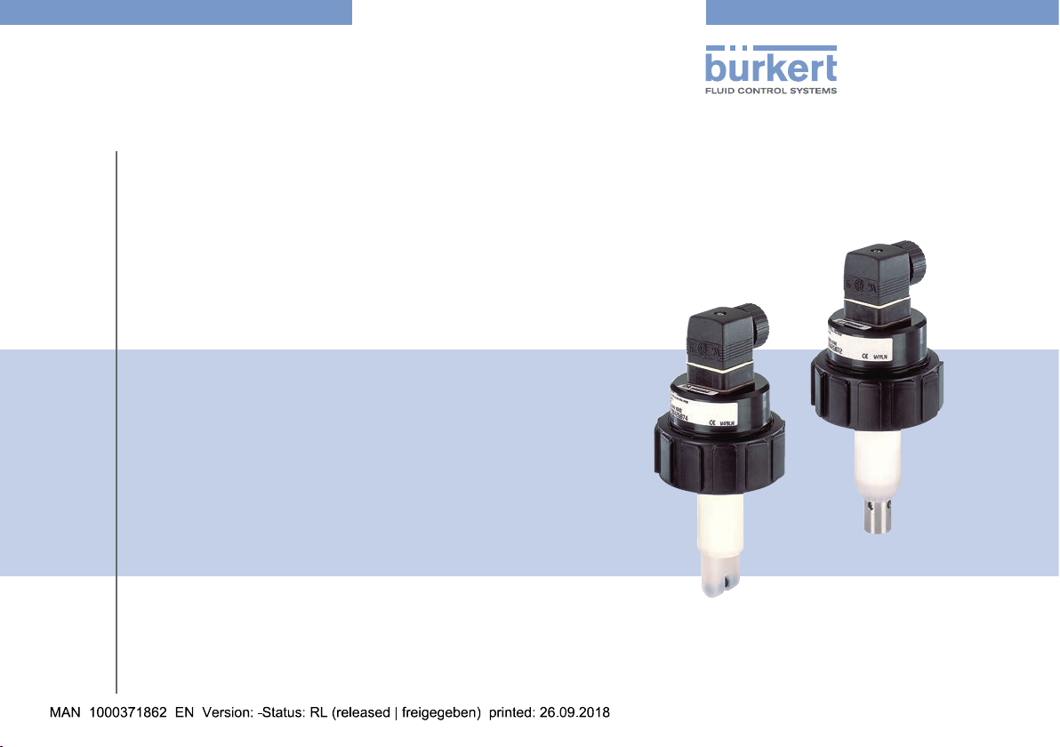
Type 8220
Leitfähigkeitssensor
Conductivity sensor
Capteur de conductivité
Operating Instructions
Bedienungsanleitung
Manuel d'utilisation
Page 2

We reserve the right to make technical changes without notice.
Technische Änderungen vorbehalten.
Sous réserve de modifications techniques.
© Bürkert SAS, 2014 - 2018
Operating Instructions 1809/01_EU-ML 00273224 / Original FR
Page 3
Type 8220
1. ABOUT THE OPERATING INSTRUCTIONS .......................................4
1.1. Definition of the word "device" ....................................................4
1.2. Symbols used .......................................................................................4
2. INTENDED USE ................................................................................................5
3. BASIC SAFETY INFORMATION ...............................................................5
4. GENERAL INFORMATION ...........................................................................7
4.1. Manufacturer's address and international contacts .........7
4.2. Warranty conditions ...........................................................................7
4.3. Information on the Internet ..........................................................7
5. DESCRIPTION ...................................................................................................7
5.1. Area of application .............................................................................7
5.2. Construction .......................................................................................... 7
5.3. Description of the name plate ....................................................8
6. TECHNICAL DATA ...........................................................................................8
6.1. Conditions of use ................................................................................8
6.2. Conformity to standards and directives ................................8
6.3. Conformity to the pressure equipment directive ...............8
6.4. Materials ..................................................................................................9
6.5. Dimensions of the device ...............................................................9
6.6. Fluid data, measurement data .................................................. 10
6.7. Sensor data .........................................................................................11
7. INSTALLATION AND WIRING ................................................................ 11
7.1. Safety instructions...........................................................................11
7.2. Installation on the pipe ................................................................. 12
7.3. Electrical wiring .................................................................................13
7.3.1. Safety instructions ..............................................................13
7.3.2. Technical data of the cables for the female
connectors, type 2508 or type 2509 .............................14
7.3.3. Assembling the female connector ...................................14
7.3.4. Ensuring the equipotentiality of the installation ............15
7.3.5. Connect the device to the transmitter ............................16
8. COMMISSIONING ........................................................................................17
9. MAINTENANCE AND TROUBLESHOOTING ..................................17
9.1. Safety instructions...........................................................................17
9.2. Maintenance of the device and the conductivity
sensor ....................................................................................................18
10. SPARE PARTS AND ACCESSORIES ...............................................18
11. TRANSPORT, STORAGE, DISPOSAL ..............................................19
English
3
Page 4
Type 8220
About the Operating Instructions
1 ABOUT THE OPERATING
INSTRUCTIONS
The Operating Instructions describe the entire life cycle of
the device. Please keep the Operating Instructions in a safe
place, accessible to all users and any new owners.
The Operating Instructions contain important safety
information.
Read the Operating Instructions from the beginning to the
end. Observe in particular the chapters"Basic safety information" and "Intended use".
▶ The Operating Instructions must be read and understood.
1.1 Definition of the word "device"
The word "device" used in the Operating Instructions always
refers to the conductivity sensor type 8220.
1.2 Symbols used
danger
Warns against an imminent danger.
▶ Failure to observe this warning can result in death or in
serious injury.
Warning
Warns against a potentially dangerous situation.
▶ Failure to observe this warning can result in serious injury
or even death.
CaUTiOn
Warns against a possible risk.
▶ Failure to observe this warning can result in substantial or
minor injuries.
nOTe
Warns against material damage.
Advice or important recommendations.
refers to information contained in the Operating
Instructions or in other documents.
→ Indicates a procedure to be carried out.
4
English
Page 5
Type 8220
Intended use
2 INTENDED USE
Use of the device that does not comply with the
instructions could present risks to people, nearby
installations and the environment.
The 8220 conductivity sensor is intended solely for the
measurement of the conductivity of liquids.
▶ This device must be used in compliance with the charac-
teristics and commissioning and use conditions specified in the contractual documents and in the Operating
Instructions.
▶ This device must be protected against electromagnetic
interference, ultraviolet rays and, when installed outdoors,
the effects of climatic conditions.
▶ Only use a device which is in correct operating condition.
▶ Store, transport, install and use the device properly.
▶ Only use the device as intended.
3 BASIC SAFETY INFORMATION
This safety information does not take into account:
• any contingencies or occurences that may arise during installation, use and maintenance.
• the local safety regulations for which the operating company
is responsible including the staff in charge of installation.
Danger due to electrical voltage
▶ Shut down the electrical power source of all the conduc-
tors and isolate it before carrying out work on the system.
▶ Observe all applicable accident protection and safety
regulations for electrical equipment.
Risk of injury due to high pressure in the installation.
▶ Stop the circulation of fluid, cut off the pressure and drain
the pipe before loosening the process connections.
Risk of injury due to high fluid temperatures.
▶ Use safety gloves to handle the device.
▶ Stop the circulation of fluid and drain the pipe before
loosening the process connections.
Risk of injury due to the nature of the fluid.
▶ Respect the prevailing regulations on accident prevention
and safety relating to the use of hazardous products.
English
5
Page 6
▶ Do not use this device in an explosive atmosphere.
▶ Do not use this device in an environment incompatible
with the materials it is made of.
▶ Do not subject the device to mechanical loads (e.g. by
placing objects on top of it or by using it as a step).
▶ Do not make any internal or external modifications to the
device.
▶ Prevent any unintentional power supply switch-on.
▶ Guarantee a defined or controlled restarting of the pro-
cess, after a power supply interruption.
▶ Observe the general technical rules.
nOTe
The device may be damaged by the fluid in contact with.
▶ Systematically check the chemical compatibility of the com-
ponent materials of the device and the fluids likely to come
into contact with it (for example: alcohols, strong or concen-
trated acids, aldehydes, alkaline compounds, esters, aliphatic
compounds, ketones, halogenated aromatics or hydrocar-
bons, oxidants and chlorinated agents).
Type 8220
Basic safety information
nOTe
Elements / Components sensitive to electrostatic discharges
▶ This device contains electronic components sensitive to
electrostatic discharges. They may be damaged if they are
touched by an electrostatically charged person or object.
In the worst case scenario, these components are instantly
destroyed or go out of order as soon as they are activated.
▶ To minimise or even avoid any damage due to an electro-
static discharge, take all the precautions described in the EN
61340-5-1 norm.
▶ Also ensure that you do not touch any of the live electrical
components.
6
English
Page 7
Type 8220
General information
4 GENERAL INFORMATION
4.1 Manufacturer's address and international contacts
To contact the manufacturer of the device, use following
address:
Bürkert SAS
Rue du Giessen
BP 21
F-67220 TRIEMBACH-AU-VAL
You may also contact your local Burkert sales office.
The addresses of our international sales offices are available
on the internet at: www.burkert.com
4.2 Warranty conditions
The condition governing the legal warranty is the conforming
use of the device in observance of the operating conditions
specified in the Operating Instructions.
4.3 Information on the Internet
You can find the Operating Instructions and technical data
sheets related to the type 8220 at: www.burkert.com
5 DESCRIPTION
5.1 Area of application
The device is intended to measure the conductivity of liquids.
The device must be connected to a transmitter (type 8619 for
example).
5.2 Construction
The device is made up of:
• a measuring sensor of physical quantities, made up of:
- 2 electrodes which measure an impedance in Ohm;
- a conductivity sensor which integrates a Pt1000 temperature probe.
• a 4-pin male fixed connector;
• a nut to fix the device to the S020 fitting.
The device does not need a separate power supply. It is energized via the remote transmitter to which it is connected.
English
7
Page 8

Type 8220
1234
789
Technical data
5.3 Description of the name plate
COND :8220-FKM-PVDF
K=1
S/N 5721
Made in France
00426874
Fig.1:Nameplateofthedevice(example)
W48ML
1. Measured quantity
2. Type of the device
3. Seal material in contact with the fluid
4. Material of the holder for the measuring sensor
5. Cell constant
6. Serial number
7. Manufacturing code
8. Conformity marking
9. Article number
5
6
6 TECHNICAL DATA
6.1 Conditions of use
Ambient temperature 0 to +60°C
Air humidity ≤ 80 %, non-condensing
6.2 Conformity to standards and directives
The applied standards, which verify conformity with the EU
directives, can be found on the EU-type examination certificate and/or the EU declaration of conformity (if applicable).
6.3 Conformity to the pressure equipment directive
→ Make sure the device materials are compatible with the fluid.
→ Make sure the pipe DN and the nominal pressure PN are
adapted for the device.
The device conforms to Article 4, Paragraph 1 of the
Pressure Equipment Directive 2014/68/EU under the following conditions:
8
English
Page 9

Type 8220
Technical data
• Device used on a piping (PS = maximum admissible pressure;
DN = nominal diameter of the pipe)
Type of fluid Conditions
Fluid group 1, Article 4, Paragraph 1.c.i DN≤25
Fluid group 2, Article 4, Paragraph 1.c.i
Fluid group 1, Article 4, Paragraph 1.c.ii
DN≤32
or PSxDN≤1000
DN≤25
or PSxDN≤2000
DN≤200
Fluid group 2, Article 4, Paragraph 1.c.ii
or PS≤10
or PSxDN≤5000
• Device used on a vessel (PS = maximum admissible pressure)
Type of fluid Conditions
Fluid group 1, Article 4, Paragraph 1.a.i PS ≤ 200 bar
Fluid group 2, Article 4, Paragraph 1.a.i PS ≤ 1000 bar
Fluid group 1, Article 4, Paragraph 1.a.ii PS ≤ 500 bar
Fluid group 2, Article 4, Paragraph 1.a.ii PS ≤ 1000 bar
6.4 Materials
Element Material
Housing PC
Screw of the connector
stainless steel
type 2508
Connector type 2508 PA
Measuring sensor holder PVDF
Pt 1000 stainless steel 1.4571 (316 Ti)
Electrodes
• sensor K=1 or K=10
• sensor K=0,1 or
• graphite
• stainless steel 1.4571 (316 Ti)
K=0,01
6.5 Dimensions of the device
→ Refer to the technical data sheet related to the device
avalaible at: www.burkert.com
English
9
Page 10

Type 8220
10
+10 +30+50 +70 +90
Technical data
6.6 Fluid data, measurement data
Pipe diameter DN15 to DN200
Process connection S020 fitting for analysis purposes
Fluid pressure PN 10
Fluid temperature and material of
the fitting S020 used, can limit
the max. admissible pressure of
the fluid (see Fig. 2)
Fluid temperature Fluid pressure and material of
the fitting S020 used, can limit
the max. admissible temperature
of the fluid (see Fig. 2)
Conductivity measurement
• Measurement range
• Measurement deviation
Temperature probe Pt 1000 integrated in the meas-
Temperature measurement
• Measurement range
• 0,05 µS/cm to 200 mS/cm
• typical: ± 3% of the MV.*
max.: ± 5% of the MV.*
uring sensor
• -50 to +150°C
Pressure (bar)
9
8
7
6
5
4
3
2
1
0
PVDF
PVC + PP
PVC (PN10)
PP (PN10)
metal
PVDF (PN10)
Temperature (°C)
Fig.2:Dependencybetweenuidpressureanduidtempe-
rature,forthe8220insertedinaS020tting,depending
onthematerialoftheS020tting
• Measurement deviation
* of the MV. = of the measured value
10
• ± 1° C
English
Page 11

Type 8220
Installation and wiring
6.7 Sensor data
Sensor K=0,01
• Measurement range
• Type of fluid
Sensor K=0,1
• Measurement range
• Type of fluid
Sensor K=1
• Measurement range
• Type of fluid
Sensor K=10
• Measurement range
• Type of fluid
• 0,05 to 20 µS/cm
• ultra pure water, pure
water
• 0,5 to 200 µS/cm
• pure water, industrial
water
• 0,005 to 10 mS/cm
• industrial water, waste
water
• 0,5 to 200 mS/cm
• waste water, concentrated
solution
7 INSTALLATION AND WIRING
7.1 Safety instructions
danger
Danger due to electrical voltage
▶ Shut down the electrical power source of all the conduc-
tors and isolate it before carrying out work on the system.
▶ Observe all applicable accident protection and safety
regulations for electrical equipment.
Risk of injury due to high pressure in the installation.
▶ Stop the circulation of fluid, cut off the pressure and drain
the pipe before loosening the process connections.
Risk of injury due to high fluid temperatures.
▶ Use safety gloves to handle the device.
▶ Stop the circulation of fluid and drain the pipe before
loosening the process connections.
Risk of injury due to the nature of the fluid.
▶ Respect the prevailing regulations on accident prevention
and safety relating to the use of hazardous products.
English
11
Page 12

Type 8220
Installation and wiring
Warning
Risk of injury due to non-conforming installation.
▶ The electrical and fluid installation can only be carried out
by qualified and skilled staff with the appropriate tools.
▶ Observe the NF C 15-100 / IEC 60364 norm.
▶ Observe mounting instructions of the fitting.
▶ Protect the installation against unintentional power supply
switch-on.
▶ Guarantee a set or controlled restarting of the process
subsequent to any intervention on the device.
Warning
Risk of injury if the dependency between the fluid
pressure and the fluid temperature is not respected.
▶ Take account of the dependency between the fluid pres-
sure and the fluid temperature, according to the materials
the fitting is made of (see Fig. 2, page 10).
▶ Observe the Pressure Equipment Directive 2014/68/EU.
Protect this device against electromagnetic interference, ultraviolet rays and, when installed outdoors,
the effects of the climatic conditions.
7.2 Installation on the pipe
The device can be installed on a pipe using a fitting type
S020 (see Fig. 3 et Fig. 4).
flow direction
Fig.3:Mountingpositionofthetting-devicesysteminthepipe
→ Install the conductivity sensor on a horizontal pipe and
position the connector upwards.
→ Install preferably the device upstream an instrument gen-
erating turbulences such as a valve.
12
English
Page 13

Type 8220
1
2
3
4
5
Installation and wiring
→ Install the fitting (mark 5) on the pipe acc.
to the Operating Instructions of the fitting
used and acc. to the Fig. 3.
→ Check that the seal (mark 6) is on the
conductivity sensor.
→ Insert the nut (mark 3) on the fitting.
→ Insert the snap ring (mark 2) in the
groove (mark 4).
→ With a cell constant K=10, point the
opening of the channel in the direction of
the fluid.
→ Slowly push the device in the fitting. If
the mounting is correctly done the device
cannot be turned around anymore.
→ Hand thighten the nut to lock the
assembly.
Fig.4:Installationofthe8220ontheS020tting
7.3 Electrical wiring
7.3.1 Safety instructions
danger
Risk of injury due to electrical discharge
▶ Shut down the electrical power source of all the conduc-
6
tors and isolate it before carrying out work on the system.
▶ Observe all applicable accident protection and safety
regulations for electrical equipment.
• Use a filtered and stable power supply.
• Do not install the cable near high voltage or high
frequency cables. If this cannot be avoided, observe
a min. distance of 30 cm.
English
13
Page 14

Type 8220
2
6
Installation and wiring
7.3.2 Technical data of the cables for the female connectors, type 2508 or type 2509
Cable technical data Recommended
Electromagnetic protection
shielded
(EMC)
Maximal length 10 m
Diameter 5...8 mm
Operating temperature minimum 80 °C
Number of wires 4
Cross section of the wires 0,25 to 1,5 mm
2
7.3.3 Assembling the female connector
→ Loosen the nut [1] of the cable gland.
→ Remove the terminal block [3] from the
housing [2].
3
→ Insert the cable in the nut [1], in the seal [4],
4
1
in the cable gland and in the housing [2].
→ Connect the 4 conductors to the terminal
block [3].
→ Position the terminal block [3] in steps of 90°
then put it back in the housing [2], pulling
gently on the cable so that the wires do not
clutter the housing.
→ Tighten the nut [1] of the cable gland.
→ Put the seal [5] between the connector
and the fixed connector on the device and
then plug the 2508 connector into the fixed
5
connector.
→ Insert and then tighten the screw [6] to ensure
tightness and correct electrical contact.
Fig.5:Assemblingthefemaleconnectortype2508(supplied)
14
English
Page 15

Type 8220
+
-
(*)
8220
PE/FE FE
Installation and wiring
7.3.4 Ensuring the equipotentiality of the installation
To ensure the equipotentiality of the installation (power supply
- device - fluid):
→ Connect the different earth points to one another of the
installation to eliminate the potential differences that may
occur between themselves.
→ Connect the negative terminal of the power supply to the
earth to eliminate the common mode currents. If direct
earthing is not possible insert a 100 nF / 50 V-capacitor
between the negative terminal and the earth.
→ When the device is installed on plastic pipes, connect
to the same earth the different metal instruments such
as a valve or a pump that are the closest possible to the
device.
→ If no such instrument is near the device, insert metal
earthing rings inside the plastic pipes upstream and
downstream the device and connect them to the same
earth.
→ Put the earthing rings in contact with the fluid.
Electrical power supply
Transmitter
Metal pipes
PE = protective earth terminal
FE = functional earth terminal
(*) If a direct earth connection is not possible, fit a 100 nF / 50 V condenser
between the negative power supply terminal and the earth.
Fig.6:Equipotentialityoftheinstallationwithmetalpipes
English
15
Page 16

Type 8220
4
123456789
Installation and wiring
Electrical power supply
+
-
(*)
Instruments such as
a valve or a pump...
PE = protective earth terminal
FE = functional earth terminal
(*) If a direct earth connection is not possible, fit a 100 nF / 50 V condenser between the negative power supply terminal and the earth.
Transmitter
PE/FE
Plastic pipes
FE
8220
Fig.7:Equipotentialityoftheinstallationwithplasticpipes
7.3.5 Connect the device to the transmitter
1
3
2
1: Positive conductivity electrode
2: Pt1000
3: Negative conductivity electrode
4: Pt1000
Fig.8:Pinassignmentofthexedconnector
Terminal block
of the connector
FE = functional earth
terminal
2508
1
3
2
C+
Conductivity module of the
transmitter 8619
P+
P-
C-
FE
TS
TS
SE
GD
16
English
Fig.9:Connectionexampleofthe8220tothetransmitter8619
Page 17

Type 8220
Commissioning
8 COMMISSIONING
Warning
Risk of injury due to non-conforming commissioning.
Non-conforming commissioning could lead to injuries and
damage the device and its surroundings.
▶ The staff in charge of commissioning must have read and
understood the contents of the Operating Instructions.
▶ In particular, observe the safety recommendations and
intended use.
▶ The device / the installation must only be commissioned
by suitably trained staff.
→ Before commissioning, set the cell constant in the appro-
priate parameter menu of the remote transmitter. Refer to
the Operating Instructions of the transmitter used.
9 MAINTENANCE AND
TROUBLESHOOTING
9.1 Safety instructions
danger
Danger due to electrical voltage
▶ Shut down the electrical power source of all the conduc-
tors and isolate it before carrying out work on the system.
▶ Observe all applicable accident protection and safety
regulations for electrical equipment.
Risk of injury due to high pressure in the installation.
▶ Stop the circulation of fluid, cut off the pressure and drain
the pipe before loosening the process connections.
Risk of injury due to high fluid temperatures.
▶ Use safety gloves to handle the device.
▶ Stop the circulation of fluid and drain the pipe before
loosening the process connections.
Risk of injury due to the nature of the fluid.
▶ Respect the prevailing regulations on accident prevention
and safety relating to the use of hazardous products.
English
17
Page 18

Type 8220
Spare parts and accessories
Warning
Risk of injury due to non-conforming maintenance.
▶ Maintenance must only be carried out by qualified and
skilled staff with the appropriate tools.
▶ Ensure that the restart of the installation is controlled after
any interventions.
9.2 Maintenance of the device and the conductivity sensor
• Do not scratch the sensor surface while cleaning it.
• Store the sensor in a dry place.
Clean the device with a cloth slightly dampened with water or
a cleaning liquid compatible with the materials the device is
made of.
→ Check regularly that the conductivity sensor is clean and
clean it with water if necessary.
Please feel free to contact your Bürkert supplier for any additional information.
10 SPARE PARTS AND
ACCESSORIES
CaUTiOn
Risk of injury and/or material damage caused by the
use of unsuitable parts.
Incorrect accessories and unsuitable replacement parts
may cause injuries and damage the device and the surrounding area.
▶ Use only original accessories and original spare parts
from Bürkert.
Spare parts (Fig. 10) Article number
Set with 1 FKM green seal (mark 5)
+ 1 EPDM black seal (mark 5)
Snap ring (mark 3) 619205
Nut (mark 4) 619204
Accessories (Fig. 10) Article number
4-pin female connector, with
cable gland (type 2508) (mark 1)
4-pin female connector, with
reduction NPT 1/2" (type 2509)
(mark 2)
552111
438811
162673
18
English
Page 19

Type 8220
NPT 1/2
1
2
3
4
5
Transport, storage, disposal
11 TRANSPORT, STORAGE,
DISPOSAL
nOTe
Damage due to transport
Transport may damage an insufficiently protected device.
• Transport the device in shock-resistant packaging and
away from humidity and dirt.
• Do not expose the device to temperatures that may
exceed the admissible storage temperature range.
• Protect the electrical interfaces using protective plugs.
Fig.10: Explodedviewoftheconductivitysensortype8220
Poor storage can damage the device.
• Store the device in a dry place away from dust.
• Device storage temperature: 0...+60 °C.
Damage to the environment caused by products contaminated by the fluid.
• Dispose of the device and its packaging in an environmentally-friendly way.
• Comply with the national and/or local regulations which
concern the area of waste disposal.
English
19
Page 20

Type 8220
20
English
Page 21

Page 22

www.burkert.com
 Loading...