

Page 1

8205 426493C
E-1-
pH CONTROLLER 8205
TABLE OF CONTENTS
1 INTRODUCTION ................................................................................................................ E-2
1.1 Unpacking and Control....................................................................................................... E-2
1.2 About this Manual .............................................................................................................. E-2
1.3 User's Responsibility for Safety ......................................................................................... E-2
1.4 Electromagnetic Compatibility ........................................................................................... E-2
2 SPECIFICATION................................................................................................................ E-3
2.1 Compact pH-Controller Type 8205 Specification .............................................................. E-3
2.2 Separate pH-Controller Type 8205 Specification .............................................................. E-3
2.3 Design and Measuring Principle ........................................................................................ E-4
2.4 Dimensions ......................................................................................................................... E-7
2.5 Technical Data ................................................................................................................... E-8
3 INSTALLATION ............................................................................................................... E-10
3.1 Installation Guidelines ...................................................................................................... E-10
3.2 Electrical Wiring ............................................................................................................... E-11
3.2.1 General Electrical Connection ................................................................................ E-11
3.2.2 pH Controller type 8205 compact ...........................................................................E-12
3..2.3 pH-Controller type 8205 panel version .................................................................. E-13
3.2.4 pH-Controller type 8205 wall-mounted 12-30 VDC................................................ E-14
3.2.5 pH-Controller type 8205 wall-mounted 115-230 VAC ............................................ E-15
4 OPERATION .................................................................................................................... E-16
4.1 Controller Operating and Control Elements .................................................................... E-16
4.2 Operation Mode Display .................................................................................................. E-17
4.2.1 Working rates control ..............................................................................................E-17
4.2.2 HOLD Function ....................................................................................................... E-18
4.2.3 Calibration of pH Electrode ..................................................................................... E-18
4.3 Calibration Mode .............................................................................................................. E-19
4.3.1 Language ................................................................................................................ E-19
4.3.2 Temperature Units .................................................................................................. E-20
4.3.3 Output Current ........................................................................................................ E-21
4.3.4 Output Signal 1 ....................................................................................................... E-22
4.3.5 Output Signal 2 ....................................................................................................... E-23
4.3.6 Setpoint adjustment ................................................................................................ E-24
4.3.7 Control Mode Selection .......................................................................................... E-25
4.3.8 Alarm Threshold Selection...................................................................................... E-26
4.3.9 Hand Display Selection ........................................................................................... E-27
4.3.10 Temperature Compensation Mode ....................................................................... E-27
4.3.11 Filter Function ....................................................................................................... E-28
4.4 Test Menu......................................................................................................................... E-28
4.4.1 Offset-Compensation .............................................................................................. E-29
4.4.2 Span-Compensation ............................................................................................... E-29
4.4.3 Temperature adjustment ......................................................................................... E-29
4.4.4 pH Simulation .......................................................................................................... E-30
4.4.5 Display of Electrode Voltage .................................................................................. E-30
5 MAINTENANCE ...............................................................................................................E-30
5.1 Replacement of the Electrode ......................................................................................... E-30
5.2 Storing and Cleaning of the Electrode ............................................................................. E-31
5.3 Error Messages ................................................................................................................E-32
5.4 Factory Setting of pH Controller Type 8205 ...................................................................E-32
5.5 Spare Parts List ................................................................................................................ E-33
Appendix Characteristics of PID controllers ............................................................. E-36
Page 2

E-2-
8205
pH CONTROLLER 8205
1 INTRODUCTION
Dear Customer,
Congratulations on your purchase of our
digital pH controller type 8205 .
BEFORE INSTALLING OR USING THIS
PRODUCT, PLEASE TAKE OUR ADVICE
AND READ THE ENTIRE MANUAL
THOROUGHLY.
This will enable you to fully profit from all of
the advantages offered by this product.
1.1 Unpacking and Control
Please verify that the product is complete
and free from any damage. The standard
delivery must include:
-1 8205 digital pH Controller
-1 Operating Instruction Manual
Compare the Type specifications on the
label to the adjacent list to ensure that you
have received the proper unit. If there is any
loss or damage, please contact your local
Bürkert subsidiary.
1.2 About this Manual
This manual does not contain any warranty
statement. Please refer to our general terms
of sale and delivery.
Only properly-trained staff should install and/
or repair this product. If difficulties
should occur at the time of installation,
please contact your nearest Bürkert sales
office for assistance.
1.3 User's Responsibility for Safety
Bürkert manufactures a broad range of pH
controllers (compact, wall-mounted or panel
versions). While each of these products is
designed to operate in a wide variety of
applications, it is the user's responsibility to
select a controller model that is appropriate
for the application, install it properly, and
maintain all components. Special Warning
must be paid to the chemical resistance of
the controller against the fluids which are
directly contacting the product.
This symbol appears in the
manual to call special warning to
instructions that affect the safe
installation, function and use of
the product.
1.4 Electromagnetic compatibility
This device conforms to the EMC-Directive
of the Council of European Communities
89/336/EEC.
In order to comply with this directive, follow
the wiring instructions.
!
Page 3

8205
E-3-
pH CONTROLLER 8205
2 SPECIFICATION
2.1 Compact pH controller type 8205 specification
pH controller compact 4-20 mA output; 2 Relay pulse outputs; 1 relay alarm
Type compact 2 x PG 13.5 2 x G 1/2"
Controller Gasket Electrode Worlwide Ident N° N.America Ident N°
8205 FPM GLS 426430Q 426460W
8205 FPM STE 426431D 426461K
8205 FPM LEI 426432E 426462L
8205 FPM SCH 426433F 426463M
8205 FPM HOL 426434G 426464N
8205 EPDM GLS 426435H 426465P
8205 EPDM STE 426436A 426466Q
8205 EPDM LEI 426437B 426467R
8205 EPDM SCH 426438L 426468S
8205 EPDM HOL 426439M 426469T
pH controller compact 4-20 mA output; 2 Triac pulse outputs; 1 relay alarm
Type compact 2 x PG 13.5 2 x G 1/2"
Controller Gasket Electrode Worlwide Ident N° N.America Ident N°
8205 FPM GLS 426440S 426470Y
8205 FPM STE 426441P 426471M
8205 FPM LEI 426442Q 426472N
8205 FPM SCH 426443R 426473P
8205 FPM HOL 426444J 426474Q
8205 EPDM GLS 426445K 426475R
8205 EPDM STE 426446L 426476J
8205 EPDM LEI 426447M 426477K
8205 EPDM SCH 426448W 426478U
8205 EPDM HOL 426449X 426479V
pH controller compact 4-20 mA output; 2 Transistor pulse outputs; 1 relay alarm
Type compact 2 x PG 13.5 2 x G 1/2"
Controller Gasket Electrode Worlwide Ident N° N.America Ident N°
8205 FPM GLS 426450U 426480K
8205 FPM STE 426451R 426481G
8205 FPM LEI 426452J 426482H
8205 FPM SCH 426453K 426483A
8205 FPM HOL 426454L 426484B
8205 EPDM GLS 426455M 426485C
8205 EPDM STE 426456N 426486D
8205 EPDM LEI 426457P 426487E
8205 EPDM SCH 426458Y 426488P
8205 EPDM HOL 426459Z 426489Q
Page 4
E-4-
8205
pH CONTROLLER 8205
2.3 Design and Measuring Principle
Design
pH controller type 8205 compact
The pH-controller compactly combines a
pH-sensor and a controller with display in
a splash-proof plastic IP65 enclosure.
The sensor component consists of a
replaceable combination pH-electrode,
screwed into the sensor housing with screwin threads PG 13.5. The measured signal is
conveyed to the controller via a coax plug.
The Pt1000 for automatic temperature
compensation is a standard feature in the
sensor housing (An option without Pt1000
is available, in this case,enter the process
temperature of the fluid cf §4.3.10).
The controller component converts the
measured signal, displays the actual value
and computes the command signals.
The output signals are provided via two PG
13.5.
2.2 Specification pH controller type 8205 Separate
pH controller type 8205 panel version
Type Pulse output Power Supply Order Nr
8205 Relays 12-30 VDC 427939K
8205 Triacs 12-30 VDC 427940Y
8205 Transistors 12-30 VDC 427941M
pH controller type 8205 wall-mounted version
Type Pulse output Power Supply Order Nr
8205 Relays 12-30 VDC 427946J
8205 Triacs 12-30 VDC 427947K
8205 Transistors 12-30 VDC 427948U
8205 Relays 115-230 VAC 427951P
8205 Triacs 115-230 VAC 427952Q
8205 Transistors 115-230 VAC 427953R
pH sensor for pH controller type 8205 separate versions.
See specific pH sensor type 8200 instruction manual.
2 SPECIFICATION
pH controller type 8205 separate
The pH transmission system combines a
pH sensor type 8200, and a separate pH
controller type 8205 with display.
The 8205 separate controller is available in
panel mounted version and in a wallmounted plastic IP65 enclosure for
connection to the pH sensor type 8200.
pH sensor type 8200
A wide range of pH sensors offers large
capabilities of mounting and pH
measurement.
The characteristics of electrodes are
described in the 8200 Operating
Manual.The Pt1000 for automatic
temperature compensation is available as
an option feature in pH sensor housings.
Page 5
8205
E-5-
pH CONTROLLER 8205
2 SPECIFICATION
WASTE WATER
WASTE WATER
ACID BASE
ACID BASE
pH 7
Measuring Principle
The most important part of a pH electrode
is the glass membrane of pH-selective glass.
When the electrode is immersed into the
solution, an electrical charge caused by Hions (H+) generates a cell voltage between
the glass membrane and the solution. This
electric voltage is recorded with reference
to a reference electrode, located around the
pH glass electrode. The cell voltage of the
combination electrode is directly
proportional to the pH value (59.16 mV per
pH unit at 25°C).
The controller functions in a 3-wire circuit
and requires a power supply of 12...30 VDC.
A relay alarm contact, and a 4...20 mA
standard signal proportional to the pH or to
the T° C, are available as output signals.
The pulse output signals are provided by
relays (standard); triacs or transistors .
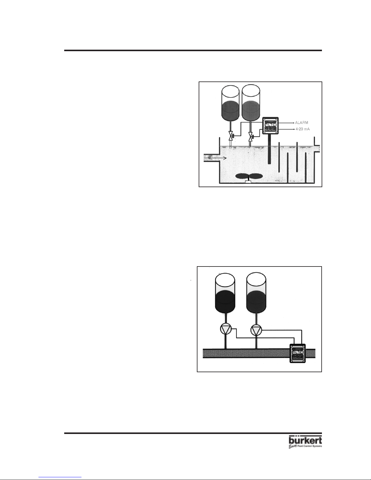
Controlling Principle
The pH controller type 8205 is designed for
use in static or dynamic process of pH
control. The output signals control a valve
(e.g.: Bürkert Type 2031) or a pump, by
means of impulses which times duration or
frequency is computed according to users
parameters and pH value of the fluid.
(See § 4.3 Operation).
A) Static process: Fluid controlled in a tank,
without significant flow, the control mode
is proportional.
B) Dynamic process: Fluid controlled in a
pipe, or in a tank with significant flow. The
control mode is PI or PID.
Fig. 2.2 Dynamic process control
The pH sensor type 8200 for pH controller
type 8205 separate version can be easily
installed into pipes using our specially
designed fitting system. Please refer to the
pH sensor type 8200 instruction manual
(Ref 428937J).
pH 7
Fig. 2.1 Static process control
Refer to Appendix A for general
characteristics of PID controllers.
Page 6
E-6-
8205
pH CONTROLLER 8205
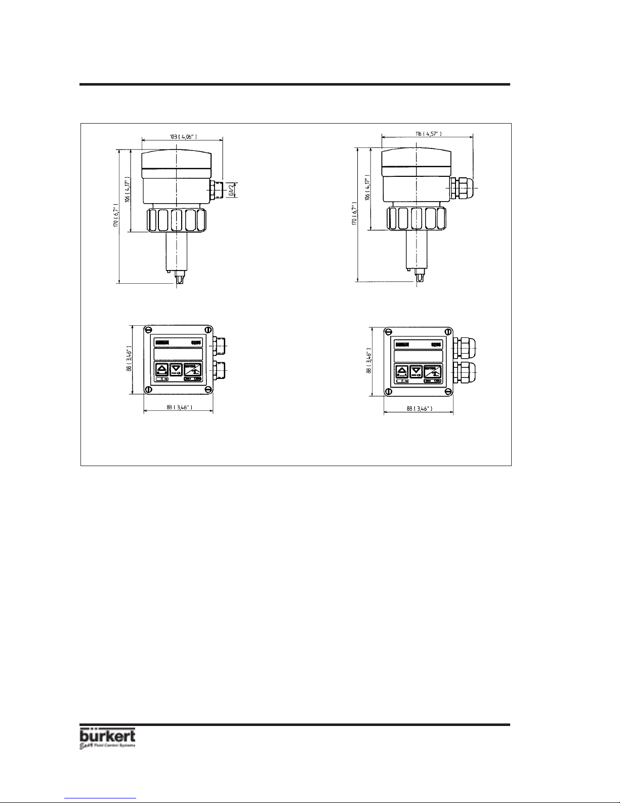
2.4 Dimensions of the pH controller type 8205 compact
PG 13,5
Version:
"STANDARD WORLWIDE"
See § 2.1
Version:
"NORTH AMERICA"
See § 2.1
G 1/2"
Fig. 2.3 Dimensions pH controller type 8205 compact
2 SPECIFICATION
Page 7
8205
E-7-
pH CONTROLLER 8205
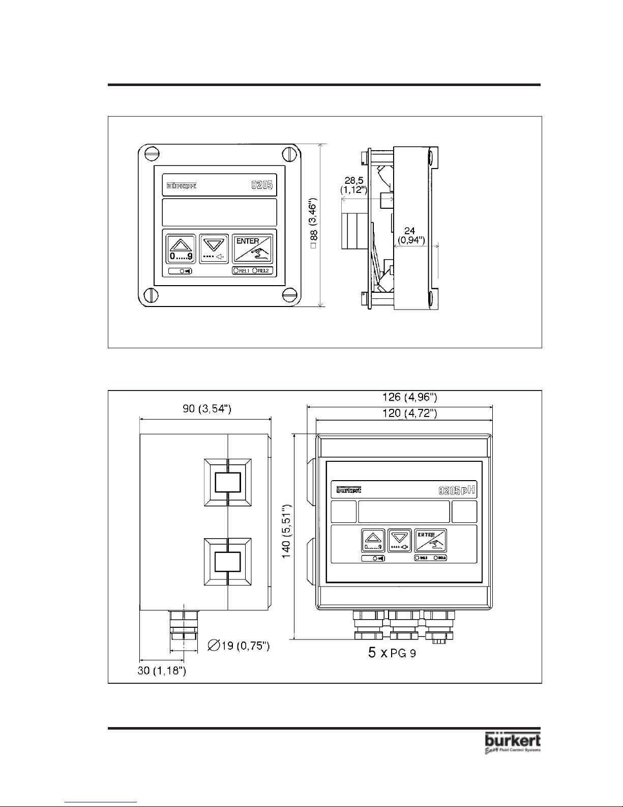
2 SPECIFICATION
covering strip
covering strip
Fig 2.4 Dimensions pH controller type 8205 panel version
+ 1 cable gland reducer
Fig 2.5 Dimensions pH controller type 8205 wall-mounted version
Page 8

E-8-
8205
pH CONTROLLER 8205
2 SPECIFICATION
2.5 Technical Data 8205 pH Controller
2.5.1 pH controller type 8205 compact version specification
Ambient temperature 0 to 60°C (32 to 140°F)
Storing temperature 0 to 60°C (32 to 140°F)
Relative humidity max 80 %
Enclosure IP 65
Measuring range 0...14 pH
Measuring error +/-0,2%, depending on electrode calibration
Temperature compensation automatic (integrated Pt1000 or user parametred)
reference temperature 25oC (77°F)
Power supply: 12...30 VDC
Output signal 4...20 mA programmable ; proportional to the pH or temperature
Load max. 1300 Ω at 30 V ; max. 1000 Ω at 24 V ; max. 550 Ω at 15 V
Display 15 x 60 mm LCD 8 digits, alphanumeric,
15 segments, 9 mm high
Relay alarm output 1 relay, 3 A, 220 V, freely adjustable
Pulse Outputs 2 frequency and time duration adjustable outputs
- Relay Pulse Output: 3 A / 250 V max ; F < 1 Hz
- Transistor Pulse Output: 300 mA / 30 V max ; F < 17 Hz
- Triac Pulse Output: 1 A / 250 V max ; F < 17 Hz
Pt1000 SS 1.4571 (Ti 316)
Control Mode P ; PI or PID programmable
Sensor housing PVDF ; O-rings FPM/EPDM
Electronics housing PC ; front plate polyester
Technical Data: Electrodes GLS STE
Housing glass shaft glass shaft
Fluid pressure 0-6 bar 0-3 bar
(0-87 psi) (0-44 psi)
Fluid temperature 0-90° C 0-130° C
(32-194°F) (32-266°F)
Max. pressure at max. temperature 4 bar (58 psi) 2 bar (29 psi)
Diaphragm zirkondioxide zirkondioxide
Reference electrolyte gel gel
LEI SCH HOL
Housing glass shaft glass shaft
Fluid pressure 0-2 bar 0-2 bar 0-6 bar
(0-29 psi) (0-29 psi) (0-87 psi)
Fluid temperature 0-60° C 0-40° C 0-90° C
(32-140°F) (32-104°F) (32-194°F)
Max. pressure at max. temperature 2 bar (29 psi) 2 bar (29 psi) 4 bar (58 psi)
Diaphragm 3 x zirkondioxide none none
Reference electrolyte KCl 3-Molar polymerised polymerised
Page 9

8205
E-9-
pH CONTROLLER 82052 SPECIFICATION
2.5.2 pH controller type 8205 separate version specification
Ambient temperature 0 to 60°C (32 to 140°F)
Storing temperature 0 to 60°C (32 to 140°F)
Relative humidity 80 %
Enclosure Wall-mounted version IP 65 ; ABS
Panel version IP 20 (rear plate) ; IP65 (front plate) ; PC
Power supply: 12...30 VDC (115/220 VAC Option wall-mounted version)
Consumption: 20 mA (with triac, or transistor) ; or 80 mA (with relays)
Output signal 4...20 mA programmable ; proportional to the pH or temperature
Load max. 1300 Ω at 30 V ; max. 1000 Ω at 24 V ; max. 550 Ω at 15 V
Display 15 x 60 mm LCD 8 digits, alphanumeric,
15 segments, 9 mm high
Relay alarm output 1 relay, 3 A, 220 V, freely adjustable
Pulse Outputs 2 frequency and time duration adjustable outputs
- Relay Pulse Output: 3 A / 250 V max ; F < 1 Hz
- Transistor Pulse Output: 300 mA / 30 V max ; F < 17 Hz
- Triac Pulse Output: 1 A / 250 V max ; F < 17 Hz
Control Mode P ; PI or PID programmable
pH sensor type 8200 guide (see pH sensor 8200 reference manual (Ref 428937J))
Technical Data: Electrodes Easycontrol Liq-Glas PG
Measuring range 0-14 1-12
Housing glass shaft glass shaft
Fluid pressure 0-2 bar 0-2 bar
Fluid temperature 0 - +60° C -5 - +60° C
Metrocode Polilyte Std Polilyte HP
Measuring range 0-14 2-14 2-14
Housing glass shaft glass shaft glass shaft
Fluid pressure 0-16 bar 0-2 bar 0-6 bar
Fluid temperature 0-+130° C 0-+40° C 0-+90° C
Temperature compensation with optional integrated Pt1000 (ref. temperature 25°C (77°F))
pH sensor type 8200 connection
Connection Material- connection size
G 2" PVC; PP; PVDF; SS
G1" PVC; PP; PVDF; SS
Sanitary SS DN40; DN50; DN65
Triclamp SS 50,5/64
Length pH Pt1000
2 m 427024H 427110Q
5 m 427025A 427113F
Cable for Pt1000 and pH
Page 10
E-10-
8205
pH CONTROLLER 8205
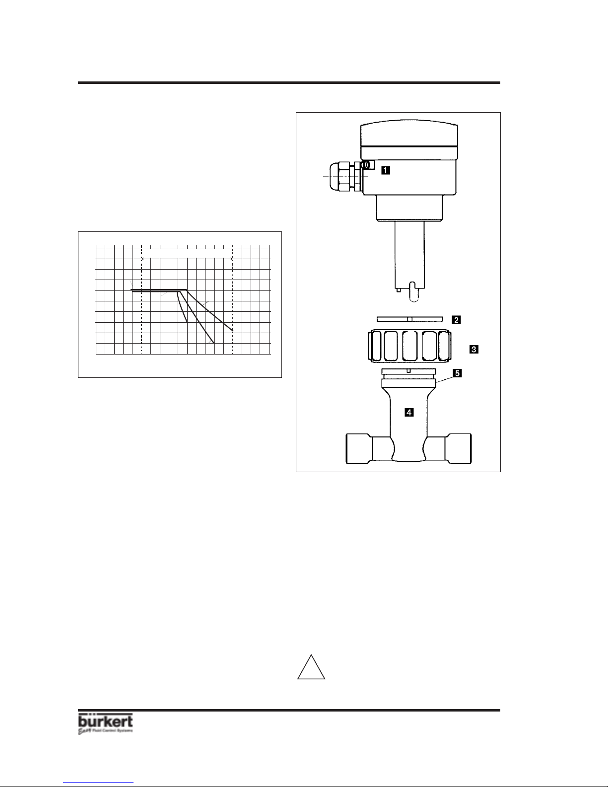
3.1.2 Compact controller type 8205
installation
The pH controller can be easily installed in
pipes using our specially designed fitting
system. Before installation, the controller
must be calibrated with buffer solutions (see
§ 4.2). Remove protective cap of the sensor.
!
Fig. 3.1 Compact controller installation
3 INSTALLATION
3.1 Installation Guidelines
Before first electrode calibration,
immerse it for 2 hours at least in buffer
solution pH=7 or in a solution of KCl 3M
(223,6 g/l) or in drinkwater.
Pressure-Temperature-Diagram
Mind pressure-temperature dependence
according to the respective fitting materials.
Installation Guidelines
Mount the compact pH controller (or pH
sensor) in vertical position (max. ±75°) into
a horizontal pipe (cf fig. 3.1).
The electrode must continuously be
immersed into the measuring fluid in order
to protect it from drying out. The device must
be protected from constant heat radiation
and other environmental influences, such
as direct exposure to sunlight.
1.The fitting must be installed into the
pipe according to the installation
specifications in section 3.1.
2.Insert plastic nut into fitting, and let
plastic ring snap into guide bush .
3.Carefully insert the pH controller into
the fitting. If installed properly, the
controller cannot be rotated.
4.Tighten controller housing to fitting with
plastic nut .
CAUTION! Plastic nut must only be
tightened by hand!
-50
-30
-10 +10
+30
+50 +70
+90
+110 +130
0
2
1
3
4
5
6
7
8
9
10
PVC + PP
PVDF
PVDF (PN 6)
PVC (PN 6)
PP (PN 6)
Application range
Page 11

8205
E-11-
pH CONTROLLER 8205
3 INSTALLATION
Front panel
For the cut-away of the front panel, follow the instructions on the enclosed delivery film.
Install the controller as follows:
1. Put gasket on the cover and place the complete unit in the panel cut-away.
2. Screw the spacer bolts on the panel fixing screws .
3. Insert the cable clips , to hold the different cables (power supply, outputs, sensor)
of the controller, into plate .
4. If a PLC is connected to the device, set the switch SW300 (cf § 3.2)
5. Plug connector on socket and fasten plate with screws on bolts , tightening
the lockwashers .
3.1.3 pH controller type 8205 panel installation
Fig 3.2 Installation pH controller type 8205 panel version
Page 12
E-12-
8205
pH CONTROLLER 8205
3 INSTALLATION
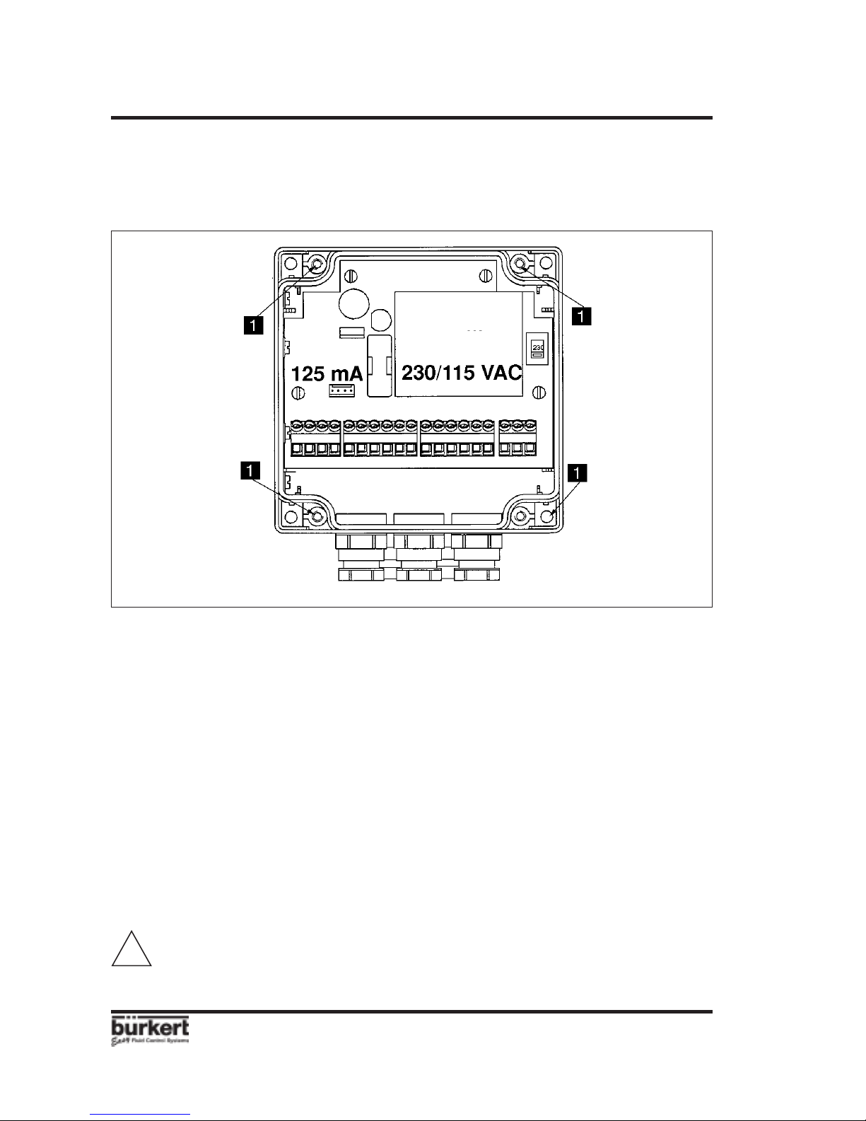
3.1.4 pH controller type 8205 Wall-mounted version installation
The pH controller in wall-mounted version has 4 fixing holes in the bottom enclosure.
Remove the white blanking stripes and the cover to access to fixing holes .
Fuse
125 mA T
Switch for power
supply selection
230/115 VAC
3.2 Electrical connection
3.2.1 General electrical requirements
The connecting line conducts the measuring signal and must not be installed in combination
with high voltage or high frequency carrying lines. If a combined installation cannot be
avoided, either keep a min. space of 30 cm (approx. 1 ft) or use shielded cables. When
using shielded cables observe faultless grounding of the shield. For normal operating
conditions, the 4-20 mA output, and relays signals can be transmitted by a simple cable
of 0.75 mm2 . In case of doubt, always use a shielded cable.
The power supply must be of good quality (filtered and regulated).
!
For EMC purposes,the earth must
be connected to the controller.
Fig 3.3 Installation pH controller type 8205 wall-mounted version
Page 13

8205
E-13-
pH CONTROLLER 8205
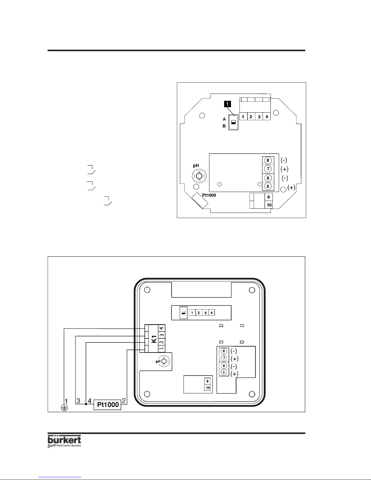
Note: PLC-connection. Depending on the PLC-version, the switch on the circuit board
must be put to position A or B (see fig. 3.4 and fig. 3.5).
Fig. 3.5 Connection of 4-20 mA output to a PLC
(Terminal type 8205 wall-mounted version)
Fig. 3.4 Pin assignment of 8205 compact
Pulse Output
relay (standard)
or triac
or transistor
Position A
0V
V+
4...20 mA
L-
8205
L+
8205
V+
L+
4...20 mA
0V
L-
Position B
9
8
10
9
8
10
SPS
SPS
3 INSTALLATION
3.2.2 Connection pH controller
type 8205 compact
The electrical wiring ensues via 2 cable
glands.
Remove the cover, pull the cable through
the cable gland and wire according to pin
assignment (Fig. 3.3).
(+ and - according to transistor signal output)
1: Current output 4...20 mA
2: L+ (12...30 VDC)
3: L- (GND)
4: Earth (earth lug)
5: Output 1
Base
6: Output 1
Base
7: Output 2
Acid
8: Output 2
Acid
9: Relay Alarm
10:
Relay Alarm
Page 14
E-14-
8205
pH CONTROLLER 8205
Fig 3.6 Electronic card type 8205 panel
3 INSTALLATION
Note: PLC-connection, depending on the
PLC-version, the switch on the circuit
board must be set in position A or B (see
Fig. 3.5 and 3.6).
Fig 3.7 Connection card pH controller type 8205 panel
Sensor connection:
Pulse Output
relay (standard)
or triac
or transistor
3.2.3 pH controller type 8205 panel
The electrical wiring ensues via 2 cable
glands.
Remove the cover, pull the cable through
the cable gland and wire according to pin
assignment (Fig. 3.6).
(+ and - according to transistor signal output)
1: Current output 4...20 mA
2: L+ (12...30 VDC)
3: L- (GND)
4: Earth (earth lug)
5: Output 1
Base
6: Output 1
Base
7: Output 2
Acid
8: Output 2
Acid
9: Relay Alarm
10:
Relay Alarm
Pt1000
blue
white
brown
black
8205
Page 15

8205
E-15-
pH CONTROLLER 8205
!
Warning: Check the position of the power supply selection switch, before starting
the device (fig 3.3).
3 INSTALLATION
3.2.4 Electrical wiring 8205 wall-mounted 12-30 VDC
Open the cover to access to the terminals. Wire according to the following figure.
Fig 3.9 115..230 VAC Power supply
RELAY
115/230 VAC
Rel Alarm
Rel Alarm
Output 1
Output 1
Output 2
Output 2
PE
N
L1
PLC
3.2.5 Electrical wiring 8205 wall-mounted 115-230 VAC
Open the cover to access to the terminals. Wire according to the following figure.
RELAY
SPARE
PLC
POWER 12/30VCC
Fig 3.8 12..30 VDC Power supply
Spare
Spare
Spare
Output (4-20 mA)
L+ (12-30 VDC)
L- (12-30 VDC)
Rel Alarm
Rel Alarm
Output 1
Output 1
Output 2
Output 2
Spare
Spare
Spare
Spare
Spare
Spare
Output (4-20 mA)
L+ (12-30 VDC)
L- (12-30 VDC)
Connect the pH sensor to the coaxial connector on the electronic board.
Use the cable gland reducer for the pH cable.
black
Pt1 brown
Pt2 white
쓔 blue
Pt1000
black
Pt1 brown
Pt2 white
쓔 blue
Pt1000
Page 16

E-16-
8205
pH CONTROLLER 8205
4 OPERATION
Display selection and
increasing key
(numeric values)
impulses or automatic.
Choice of digit value
Steps from 0 to 9
PH
=
7.25
Relay Alarm: contact closed
Relay 2: contact closed
(Acid)
Acceptance of chosen
parameter or adjusted
value
4.1 Controller Operating and Control Elements
Direction downwards
in menu or sideways
for digit selection
Relay 1: contact closed
(Base)
The operation of the pH controller is classified according to 3 levels.
Main Menu
pH, temperature, output current, setpoint and working rates are displayed in the normal
function mode.
The "HOLD" function and electrode calibration function ("PH CALIB") can be accessed in this
menu. (see § 4.2)
Calibration Menu
The calibration mode allows adjustments of language, units, 4...20 mA output, output
frequencies and impulse durations, pH setpoint adjustment, regulation principle (P; PI;
PID), alarm thresholds, manual display selection, temperature compensation mode, and
filter selection. (see § 4.3).
Test Menu
The test menu allows the basic setting of the controller (Offset, Span, temperature
adjustment).
A pH or temperature value can be simulated via this menu, allowing the process to be
tested in the "dry condition".
The display of the instantaneous electrode voltage is available. (see § 4.4)
Page 17

8205
E-17-
pH CONTROLLER 8205
S2=7.5
S1=6.5
ENTER
PH = 12.60
57 % 1
PH = 12.60
ENTER
ENTER
0......9
0......9
ENTER
PH = 12.60
000 % 1
100 % 1
0......9
000 % 2
000 % 1
2 s
+
0......9
4 OPERATION
4.2 Operation Mode Display
The following process values are displayed in the display operation mode.
20.6 °C
Temperature in °C or °F.
pH with two decimals. Press to display the working
rates control function.
HOLD
HOLD-function. (quick blincking)
PH CALIB
Calibration of the pH electrode signal.
PH = 12.60
10.32 mA
Output signal 4...20 mA, proportional to the pH or temperature
value.
4.2.1 Working rates control function
Allow the current working rates to be checked for output 1 (Base) and output 2 (Acid).
If the HAND option is enabled (see § 4.3.9) , the change of percentage rates is allowed
in this sub-menu, by pressing simultaneously the keys and during 2 sec.
ENTER
0......9
(only available if HAND option enabled)
Reactive selection
Base
Acid
Output percentage
adjustment
Page 18

E-18-
8205
pH CONTROLLER 8205
ENTER
ENTER
HOLD
HOLD NO
HOLD YES
Press Enter for
5 seconds
PH CALIB
4.2.2 HOLD function
A continuous 4-20 mA output corresponding to the last value measured before this option
was entered is generated. The relays are blocked in their last state. This allows the
electrode to be cleaned without interruption of the process. The display in the operation
mode is flashing and there is no access to the parameter definition or the test menu, as
long as the HOLD-function is activated. To disactivate HOLD function, enter again "HOLD"
option and confirm "HOLD NO".
4.2.3 Calibration of pH electrode
1 or 2 measuring points calibration methods are available.
1 measuring point method: enables a quick control calibration with pH=7 buffer solution.
2 measuring points method: enables a precise calibration of zero and slope of the pH
electrode. 2 buffer solutions are required. The first solution is usually pH=7. Use the
second buffer solution as close as possible of the assumed final pH value. Before each
calibration, clean the electrode (see §5.2). The temperatures of the buffer solutions must
be equal. The pH controller must be calibrated regularly.
This maintenance procedure is very important to ensure a reliable control operation.
The frequency of calibrations depends upon the degree of contamination of the measuring
fluid: in normal conditions, calibration should be repeated once a week.
4 OPERATION
Page 19

8205
E-19-
pH CONTROLLER 82054 OPERATION
0......9
ENTER
ENTER
ENTER
ENTER
ENTER
ENTER
ENTER
ENTER
ENTER
ENTER
ENTER
ENTER
ENTER
0......9
ENTER
ENTER
PH CALIB
PH = 9.25
1 POINT PH = 7.00
CALIB . . .
2 POINTS BUFFER 1
PH=07.05
CALIB . . .RINSE
BUFFER 2 PH=00.00
PH=04.00
CALIB . . .
PH = 9.25
PH=00.00
Immerse electrode in
buffer solution and confirm
Immerse electrode in
buffer solution and confirm
Immerse electrode in
buffer solution and confirm
To escape electrode calibration, press + simultaneously for 2s.
Previous calibration values are kept.
The message "WARNING" at the end of calibration indicates
a buffer solution error or advanced ageing of the electrode.
In this case, a change of electrode must be foreseen.
The message "ERROR" at the end of calibration indicates a
buffer solution error or that the electrode is out of tolerances.
In this case, values of previous calibration are kept. The
electrode must be changed, otherwise the measured values
would be erroneous.
OFF= -18.6
SP= 57.53
OFF= -5.1
Automatic confirmation
(approx. 20 s.) or press
ENTER
Enter buffer value
Automatic confirmation
(approx. 20 s.) or press
ENTER
Enter buffer value
Automatic confirmation
(approx. 20 s.) or press ENTER
Press Enter fo 5 sec.
0......9
Page 20

E-20-
8205
pH CONTROLLER 8205
ENTER
ENTER
ENGLISH
DEUTSCH
FRANCAIS
ITALIANO
SPANOL
4 OPERATION
4.3 Calibration Mode: Press simultaneously for 5 seconds
The following adjustments are set in the calibration mode display:
ENTER
4.3.1 Language
The selected language is
confirmed by the ENTER key and
becomes immediately active.
English, German, French, Italian, or Spanish choice.
Temperature unit selection (°C; °F).
Adjustment of the 4...20 mA measuring range (pH or T°).
Selection of output signal 1 (impulse duration or frequency).
Selection of output signal 2 (impulse duration or frequency).
Adjustement of 2 setpoint for pH control (high/low or high/
very high;...).
CONTROLL
Selection of the pH control mode (P; PI; PID).
Adjustement of 2 alarm thresholds for pH or temperature
(high/low or high/ very high;...).
Manual operation selection.
Back to the operation mode and storage of new parameters.
Damping selection. 10 different steps available.
Selection of the temperature entry Pt1000 or Manual
(without Pt1000). Entry of the simulation value.
0......9
LANGUAGE
CURRENT
OUTPUT 1
OUTPUT 2
SETPOINT
ALARM
HAND
END
FILTER
T° UNIT
T° SENSOR
LANGUAGE
T° UNIT
Page 21

8205
E-21-
pH CONTROLLER 8205
4 OPERATION
4.3.2 Temperature units
The temperature can be displayed in °Celsius or in °Fahrenheit.
4.3.3 Output Current
Enter the measuring range corresponding to the 4...20 mA output. First select the unit pH
or T°current then, enter the limit values . E.g. 2 to 12 pH associated to 4...20 mA. The
beginning of the measuring range might be larger than the end of it, e.g. 2 to 12 pH
corresponds to 20...4 mA (inverted output signal).
CURRENT
RELAY
Enter the
beginning
of the
measuring
range
End of the
measuring
range
0......9
0......9
ENTER
ENTER
m
A ... PH
m
A ... ° C
4
=
00.00
4
=
02.00
20= 00.00
20
=
12.00
ENTER
ENTER
!
If the beginning of the measuring range equals the end of it, there will be no
display of the current value in the operation mode display (§4.2)
ENTER
ENTER
°CELSIUS
°
FAHRENH
T° UNIT
CURRENT
Page 22

E-22-
8205
pH CONTROLLER 8205
ENTER
ENTER
0......9
0......9
ENTER
ENTER
ENTER
0......9
0......9
ENTER
4.3.4 Output 1 (Base)
Select the controller output 1 logic signal.
Impulse time selection (PULSE 1)
Set the duration of each impulse and the maximum frequency of the output signal.
Impulse frequency selection (PWM1)
Set the frequency of the logic output signal activation.
OUTPUT 1
OUTPUT 2
PWM 1
T1=000,0S
OUTPUT 2
000 / MIN
012 / MIN
T1=012,3S
T1=000,0S
T1=001,5S
(T1 (s)+0,02 (s)) x F1 < 60
Internal checking of this condition
is provided. If this is not, the
program returns to T1 selection
until complying with the required
condition.
Impulse
Duration
(T1)
Impulse
Frequency
(F1)
Impulse
Duration
(T1)
PULSE 1
4 OPERATION
!
If the pulse output is provided by a relay; set F1 < 60. (cf § 2.5)
Page 23

8205
E-23-
pH CONTROLLER 8205
ENTER
ENTER
0......9
0......9
ENTER
ENTER
ENTER
0......9
0......9
ENTER
OUTPUT 2
SETPOINT
PWM 2
T2=000,0S
PULSE 2
SETPOINT
000 / MIN
012 / MIN
T2=012,3S
T2=000,0S
T2=001,5S
(T2( s)+ 0,02(s)) x F2 < 60
Internal checking of this condition
is provided. If this is not, the
program returns to T2 selection
until complying with the required
condition.
Impulse
Duration
(T2 s)
Impulse
Frequency
(F2)
Impulse
Duration
(T2 s)
4.3.5 Output 2 (Acid)
Select the controller output 2 logic signal.
Impulse time selection (PULSE 2)
Set the duration of each impulse and the maximum frequency of the output signal.
Impulse frequency selection (PWM2)
Set the frequency of the logic output signal activation.
4 OPERATION
!
If the pulse output is provided by a relay; set F2 < 60. (cf § 2.5)
Page 24

E-24-
8205
pH CONTROLLER 8205
4.3.6 Setpoint Adjustment
Select the pH curve setpoints.
L1<L2 and S1<=S2 (1)
Limit 1 (L1) Set the low bow of the pH curve.
Setpoint 1 (S1)
Set low limit of the pH regulation curve
Setpoint 2 (S2)
Set the high limit of the pH regulation curve.
Limit 2 (L2)
Set the high bow of the pH curve
4 OPERATION
!
If the condition (1) is not fullfilled, the menu points on L1=3.00. Valuble values
have to be selected, before leaving the menu.
ENTER
ENTER
0......9
ENTER
ENTER
0......9
L1
S1
S2
L2
pH
L1=03.00
L1=03.50
L2=11.00
L2=10.50
Volume
0......9
S1=06.0
S1=06.50
ENTER
0......9
S2=07.00
S2=07.50
SETPOINT
REACTIVE
CONTROLL
Page 25

8205
E-25-
pH CONTROLLER 8205
4.3.7 Control Mode
Selection of Control Mode (static or dynamic) and corresponding calculation parameters
for P; PI; or PID functions (Pleas refr to appendix A1).
4 OPERATION
CONTROLL
STATIC
DYNAMIC
CONTRL2
Proportional factor
Proportional factor
* Respectively KP2; TN2;
TV2 if CONTRL2 selected.
Derivative factor
*
*
*
*
Integral factor
BASE
BASE
ACID
If TV1=0.0, then control mode is PI.
CONTRL2
CONTRL1
ACID
CONTRL1
CONTROLL
0......9
ENTER
ENTER
0......9
0......9
TN1 = 1.0
TN1 = 2.0
TV1 = 1.1
ENTER
ENTER
0......9
KP1 = 1.00
KP1 =7.00
KP1 = 1.00
KP1=27.00
0......9
ENTER
ENTER
ENTER
TV1 = 1.1
CONTROLL
Page 26

E-26-
8205
pH CONTROLLER 8205
4 OPERATION
4.3.8 Alarm Threshold Selection
2 thresholds are set for the relay Alarm: MIN and MAX. Options to invert the relays and
set a delay between 0 and 999 seconds are available. The delay prevents the relay from
too fast activation, e.g. when time for homogenization is required (measurements in tanks
with agitator). If the pH(or T°) exceeds a threshold, the controller awaits the delay before
activating the relay. No alarm will be provided, if the measured pH(or T°) returns to a
normal value before the delay is elapsed.
Caution! The following condition must be maintained MIN ≤ MAX; and ∆ pH> 0,2
(or ∆ T° > 2°C) .
OPEN
MANUAL
!
Delay
Delay
Delay
closed
open
ALARM
ENTER
ENTER
0......9
ENTER
ENTER
ENTER
0......9
ENTER
0......9
pH / T°
min
max
∆ pH > 0,2
∆ T° > 2° C
MAX
MIN
pH
T° (°C/°F)
0
1
T(s)
INV YES
INV NO
DEL.1=030
DEL.1=000
MAX=06.50
MAX=00.00
MIN=01.50
MIN=00.00
PH ALARM
° C ALARM
Page 27

8205
E-27-
pH CONTROLLER 8205
+ 023
+ 045
ENTER
ENTER
0......9
ENTER
4 OPERATION
ENTER
ENTER
4.3.9 Hand Display Selection
Select the Hand display mode to allow the manual entry of percentages values of base
and acid outputs.
4.3.10 Temperature CompensationMode
If the Pt1000 is not used for temperature acquisition, select SENSOR NO and enter the
temperature of the fluid.
NO
FILTER
FILTER
SENSOR T°
NO
YES
SENSOR T°
YES
HAND
Page 28

E-28-
8205
pH CONTROLLER 82054 OPERATION
4.3.11 Filter Function
The damping is set in this sub-menu, which prevents display and output current fluctuations.
There are 10 steps available. However, the first step ("FILTER 0") has no damping function.
0......9
END
SPAN
SIMUL
Temperature value correction. The outputs are reacting
according to this input.
pH or temperature value to be simulated. The outputs are
reacting according to this input.
Electrode voltage display.
0......9
ENTER
T° ADJUST
OFFSET
Zero point compensation (4 mA).
Span compensation (20 mA).
Return to the operation mode and storage of new parameters
for OFFSET and SPAN and T° adjustment. If one of the
values is erroneous, the device points on "OFFSET", and new
values must be entered.
4.4 Test Menu: Press simultaneously for 5 seconds
The following compensations and controls are carried through in the Test menu:
VOLTAGE
FILTER
VOLTAGE
FILTER 9
FILTER 0
ENTER
ENTER
0......9
Page 29

8205
E-29-
pH CONTROLLER 8205
4.4.1 Offset-Compensation
In order to check and modify the basic setting of 4 mA, connect an ammeter in the output
circuit. Press ENTER when "OFFSET" is displayed, the controller generates 4 mA. If the
measured value is different from 4 mA, enter the measured value as offset value.
0......9
ENTER
ENTER
OFFSET
SPAN
4 OPERATION
Enter the measured value
OF= 04.02
OF= 04.00
4.4.2 Span-Compensation
Check and modify the basic setting of 20 mA. The procedure is identical to the Offsetcompensation. The controller generates 20 mA, if the ENTER key is pressed when
"OFFSET" is displayed. Correct the span value by entering the measured value if necessary.
Enter the measured value
0......9
ENTER
ENTER
SPAN
T ° ADJUST
The temperature adjustment remains active until another value is entered.
The temperature adjustment is not valid with manual temperature compensation mode.
4.4.3 Temperature adjustment
The temperature value issued from the Pt1000 can be corrected. Enter the required offset
of temperature (within the limit +/- 5°C), then valid. The temperature unit is as selected
in previous parameter menu. The selected temperature value influences the computed
pH value.
SP= 19.96
SP= 20.00
Enter the temperature
offset value (°C or °F)
SIMUL
+ 0.0 ° C
+ 1.2 ° C
0......9
ENTER
ENTER
T ° ADJUST
Page 30

E-30-
8205
pH CONTROLLER 82054 OPERATION
4.4.4 pH Simulation
A pH (or T°) value can be simulated in this menu, allowing the user to test his system
without any liquid. The simulated value influences the current and pulse outputs and the
alarm relay.
Quit the sub-menu SIMUL by pressing or
The simulation remains active until the user enters another sub-menu.
4.4.5 Display of electrode voltage
Display of the instantaneous value of the electrode voltage.
5 MAINTENANCE
5.1 Replacement of the pH electrode (compact controller only)
pH-electrodes have a limited service life, depending upon many parameters, such as the
chemical composition of the handled fluid, temperature, pressure, etc.
The electrode must be replaced if it shows visible damage (broken glass, fractures, etc.)
or if the messages "WARNING" or "ERROR" are displayed at the end of calibration.
For replacement, proceed as follows:
0......9
ENTER
ENTER
0......9
ENTER
ENTER
0......9
ENTER
0......9
Enter the pH value
SIMUL
PH=00.00
PH=10.50
PH SIMUL
Enter the temperature value
T ° SIMUL 00.0 ° C
021 ° C
SIMUL
SIMUL
ENTER
ENTER
END
SIMUL
-456 m V
Page 31

8205
E-31-
pH CONTROLLER 82055 MAINTENANCE
!
Fig. 5.1 Replacement of pH electrode
5.2 Storing and Cleaning of the Electrode
When not in operation, the electrode should be stored in a 3 molar potassium chloride
solution (223,6 g/l), providing a regenerative effect. Is there no such solution available,
normal tap water will also do for short measuring interruptions of max. 2 - 3 days. The
electrode must not be stored in distilled or deionisized water, which may be used for
rinsing purposes only!
Experience has shown, that the majority of failures in pH electrode measurements and
long response times originate from contaminated electrodes or diaphragms. Since the
contamination is subject to the application, there is no general detergent available yet.
The following detergents, however, can be recommended for most application cases:
-Greasy or oily deposits must be removed with a tenside-containing agent.
-Chalky deposits and metal hydroxide layers require diluted hydrochloric acid (10%).
-Sulphide-containing deposits (purification systems) are removed with a detergent mixture
of diluted hydrochloric acid (10%) and saturated pepsin.
-For very slow pH-electrodes dip the electrode for 1 minute into a 2% HF and 5% HCL
solution and rinse thoroughly.
Observe safety regulations, when handling acid-containing solutions. Always rinse
electrode with deionisized water and leave for approx. 10 minutes in a 3 molar
potassium chloride solution or in tap water.
!
1. Disconnect supply voltage and
make sure that there is no pressure
on pipe or tank.
2.Remove the controller from the pipe or
submersion assembly.
3.Unscrew the cover and open it slightly.
4.Pull out connectors and .
5.Pull sensor assembly out of the
enclosure.
6. Screw electrode out of assembly with
SW17 wrench.
7.Screw new electrode into assembly and
tighten with SW17 wrench. Reassemble
in reverse order.
Torque of the electrode 2 N.m
Page 32

E-32-
8205
pH CONTROLLER 82055 MAINTENANCE
5.3 Error messages
"ERROR" on the display (except in electrode calibration function) indicates that calibration
data are lost. By pressing ENTER, the user access to operation menu but the device works
with the factory settings (see §5.4). The controller needs re-calibration. If this message
recurs, please return the controller to your supplier.
Temperature: If "----° C" or "----° F" is displayed, temperature is out of range (-40...+150)
or connection with Pt 1000 is interrupted. In this case "PH = --" is displayed. For the outputs
(current and relays) pH=0 is fixed.
pH values out of range: pH>14 or pH<0, "PH = --" is displayed. For the outputs (current
and relays) pH=14, respectively pH=0, are fixed.
Electrode voltage: >+575 mV ou <-575 mV. "PH = --" and "---- mV" are displayed. For the
outputs (current and relays) pH=0, respectively pH=14, are fixed.
Power failure: In case of power failure, the display turns off, 4-20 mA and pulse output
to 0, alarm relays open. When the power supply is turned on , the controller is set to the
previous configuration and the measure goes on.
Language: English
Temperature Unit: °C
4-20 mA Output: pH
4 mA: 00.00
20 mA: 00.00
Output1: Type Pulse
Time 1: 0
Freq 1: 0
Period 1: 0 (
PWM1
)
Output2: Type Pulse
Time 2 0
Freq 2: 0
Period 2: 0 (
PWM2
)
Setpoint: Limit1: 3.00
Set1: 6.00
Set2: 8.00
Limit2: 11.00
Controller: Type : PID
Proportional KP1: 1.0 KP2: 1.0
Integer TN1: 1.0 TN2: 1.
Derivative TV1: 1.1 TV2: 1.1
Alarm: Type pH
MIN: 00.00
MAX: 00.00
DEL1: 000
INV: No
MANUAL: Yes
Pt1000: Yes
Filter: Filter 2
5.4 Factory-setting of pH controller type 8205 at delivery
Page 33

8205
E-33-
pH CONTROLLER 82055 MAINTENANCE
5.5 Spare Parts List pH controller type 8205
5.5.1 Spare Parts pH controller type 8205 compact
Position Specification Order-No.
1 Complete sensor housing with ring, union nut 425526B
and two flat seals.
2 Cover with screws, sheeting and printed circuit board
Controller with relay output, software. 426490M
Cover with screws, sheeting and printed circuit board
Controller with triac output, software. 426491A
Cover with screws, sheeting and printed circuit board
Controller with transistor output, software. 426492B
3 PG 13.5 Worldwide version 418339Q
4 PG 13.5 North America version (G 1/2 ") 418340M
5 Ring 619205L
6 Union nut 619204K
7 pH electrode 0...90°C, 0...6 bar LEI (cf §2.4) 418341A
pH electrode 0...40°C, 0...2 bar SCH 418343C
pH electrode 0...90°C, 0...6 bar HOL 420101Z
8 pH electrode 0...90°C, 0...6 bar GLS 634505Y
9 pH electrode 0...130°C, 0...3 bar STE 634506Z
10 Electrode housing with Pt 1000 stainless steel 418889Z
Electrode housing with Pt 1000 titanium 418890W
11 FPM seal kit 425554P
EPDM seal kit 425555Q
12 Operating instructions manual (D, GB, F) 426493C
13 Buffer solution pH= 4, 250 ml 418540E
Buffer solution pH= 7, 250 ml 418541T
Buffer solution pH= 9, 250 ml 418542U
Buffer solution pH= 10, 250 ml 418543V
Storage solution for electrodes (KCl 3M) 418557T
Page 34

E-34-
8205
pH CONTROLLER 8205
5 MAINTENANCE
Fig. 5.2 Spare parts explosion drawing pH controller type 8205 compact version
Page 35

8205
E-35-
pH CONTROLLER 8205
5 MAINTENANCE
5.5.2 Spare parts pH controller type 8205 panel version
Item Designation Order Nr
1
Cover with screws, front panel and electronic card with relays,
426490M
and software.
2
Cover with screws, front panel and electronic card
with triacs, 426491A
and software
2
Cover with screws, front panel and electronic card
with transistors, 426492B
and software.
3 Gasket 419350Q
4 Protective plate 427100X
5 Mounting accessories (screws, lockwashers,
spacer bolts, cable clips) 418388A
Instruction manual 426493C
Fig 5.3 Spare parts explosion drawing pH controller type 8205 panel version
Panel
Page 36

E-36-
8205
pH CONTROLLER 8205
5 MAINTENANCE
Fig 5.4 Spare Parts Explosion Drawing pH controller type 8205 wall-mounted
Item Designation Order Nr
6
Electronic card 8205 wall-mounted with relays
and software. 426987B
7
Electronic card 8205 wall-mounted with transistors
and software. 426488L
7
Electronic card 8205 wall-mounted with
triacs
and software. 426989M
8 Power card 12...30 VDC 426976P
Power card 230/115 VAC 426975N
9 Connection cable between power card
and electronic card 420403Y
10 Complete IP65 enclosure 418389B
Instruction manual 426493C
5.5.3 Spare parts pH controller type 8205 wall mounted
Page 37

8205
E-37-
pH CONTROLLER 8205
t
t
X
Y
Xd
Kp.Xd
A1: Characteristics of PID controllers
A PID controller has a proportional, an integral and a differential component (P, I and D components).
P component :
Function :
Y = Kp • Xd
Kp is the proportional action coefficient. It results from the ratio of the manipulating range ∆Y to the
proportional range ∆Xd.
Proportional range
Characteristic Step response
Characteristics :
Theoretically, a pure P controller operates without delay, i. e. it is fast and therefore dinamically
favorable. It has a lasting system deviation, i. e. it does not balance out the effects of disturbances
completely and is therefore relatively unfavorable from the static point of view.
I component :
Function :
Y = ƒ Xd dt
Ti ist the integration or manipulating time. This is the time that elapses before the manipulated
variable has passed through the complete manipulating range.
APPENDIX
range
Y
Xd
Y0
Ymax
Ymin
Xd
Y
Page 38

E-38-
8205
pH CONTROLLER 8205
Xd
Xd
dY
dt
Characteristic Step response
Characteristics :
A pure I controller eliminates the effects of occuring disturbances completely. Therefore, it has a
favorable static response. Owing to its finite manipulating speed, it operates more slowly than the P
controller and tends to oscillate. Therefore, it is relatively unfavorable from the dynamic point of view.
D component :
Function :
Y= Kd
Kd ist the derivative action coefficient.
The higher Kd is, the stronger the D influence is.
APPENDIX
Step response
Characteristics :
A controller with a D component reacts to changes in the controlled variable and is accordingly
capable of dissipating occurring deviations faster.
Control range
Manipulating
time
range
∆Y
t
t
X
Y
Xd
t
t
X
Y
Xd
Ymax
Ymin
Ti
Page 39

8205
E-39-
pH CONTROLLER 8205
Supperposition of P-, I- and D components:
Y = Kp Xd + ƒ Xd dt + Kd
Where Kp•Ti = Tn and = Tv, results with regard to
functioning of the PID controller:
Y = Kp (Xd + ƒ Xd dt + Tv )
Kp :
Proportional action coefficient / gain
Tn :
Reset time
(the time needed to achieve the same manipulated variable change by the I
component as is produced as the result of the P component).
Tv :
Derivative action time
(the time to achieve a specific manipulated variable on the basis of
the D component earlier than when using a pure P controller).
APPENDIX
1
Ti
d Xd
dt
1
Tn
d Xd
dt
Kd
Kp
t
t
X
Y
Xd
}
}
Tn
Reset time
D component
I component
P component
Step response of the PID controller
Page 40

E-40-
8205
pH CONTROLLER 8205
t
X
APPENDIX
Figure : Progression of the control variable at the stability limit
The proportional action coefficient set at the stability limit is referred as Kcrit. The resulting oscillation
period is referred to as Tcrit.
A2: Rules for adjusting PID controllers
The litterature on control systems specifies a series of adjustment rules with which a favorable
adjustment of controller parameters can be achieved experimentally. To avoid bad adjustments, the
conditions under which the respective adjustment rules have been elaborated must always be
observed. In addition to the characteristics of the controlled system and of the controller itself, it is
important to know whether it is intented to balance out a disturbance change or a command variable
change.
Adjustment rules according to Ziegler and Nichols (oscillation method)
When using this method, controller parameters are adjusted on the basis of the control loop's
response at the stability limit. In doing so, the controller parameters are adjusted so as to ensure that
the control loop begins to oscillate. A conclusion as to a favorable adjustment of the controller
parameters is reached from critical characteristic values occurring in this case. It goes without saying
that, when using this method, it must be possible to bring the control loop to oscillation.
Method:
- Set the controller as a P controller (i.e. Tn = 999, Tv = 0), initially selecting a low Kp value.
- Set the required setpoint.
- Increase Kp until the controlled variable oscillates continuously without attenuation (see following
figure).
Tcrit
Actual value
Page 41

8205
E-41-
pH CONTROLLER 8205
On the basis of Kcrit and Tcrit, the controller parameters can then be calculated in accordance with
the following table:
Parameter settings according to Ziegler und Nichols :
Controller type Parameter settings
P controller Kp = 0,5 Kcrit
P controller Kp = 0,45 Kcrit Tn = 0,85 Tcrit
P controller Kp = 0,6 Kcrit Tn = 0,5 Tcrit Tv = 0,12 Tcrit
The Ziegler and Nichols adjustment rules were determined for P systems with a time delay of the first
order and a dead time. However, they apply only to controllers with a disturbance response, but not
to controllers with a command response.
Adjustment rules according to Chien, Hrones and Reswick (manipulated variable methode):
When using this method, the controller parameters are adjusted on the basis of the control system's
transition response. A 100% change in the manipulated variable is output. The time Tu and Tg are
derived from the progression of the actual value of the control variable (following figure). Ks is the
proportional action coeffficient of the control system.
APPENDIX
t
X
Tu
Tg
KS.
Y
X
t
t
Figure : Progression of the controlled variable after a manipulated variable change ∆Y
Method :
- Set the controller to MANUAL mode.
- Output a manipulated variable change and record the controlled variable with a recorder.
- Switch off in good time if you encounter critical progressions (e. g. a risk of overheating) (Pay
attention to the fact that, in thermally inert systems, the actual value of the controlled variable may
increase further switching off).
Actual value
Page 42

E-42-
8205
pH CONTROLLER 8205
APPENDIX
As shown in the figure of the previous page, the proportional action coefficient Ks of the control
system can be calculated by way of the increase in the inflectional tangent, i. e. by way of ∆Xd / ∆t
(∆Y: manipulated variable change)
Ks =
∆X • Tg
∆t • ∆Y
The following table lists the settings for the controller parameters depending on Tu, Tg and Ks for
command and disturbance response and for an aperiodic control operation as well as a control
operation with 20% overshoot. They apply to systems with a P response, with a dead time and with
a delay of the 1st order.
Parameter settings according to Chien, Hrones and Reswick :
Parameter settings
Controller
type Aperiodic control operation Control operation with
(0% overshoot) 20% overshoot
Command Disturbance Command Disturbance
P controller KP = 0,3 Kp = 0,3 Kp = 0,7 Kp = 0,7
PI controller Kp = 0,35 Kp = 0,6 Kp = 0,6 Kp 0,7
Tn = 1,2 Tg Tn = 4 • Tu Tn = Tg Tn = 2,3 • Tu
PID controller Kp = 0,6 Kp = 0,95 Kp = 0,95 Kp = 1,2
Tn = Tg Tn = 2,4 • Tu Tn = 1,35 • Tg Tn = 2 • Tu
Tv = 0,5 • Tu Tv = 0,42 • Tu Tv = 0,47 • Tu Tv = 0,42 • Tu
Tg
Tu • Ks
Tg
Tu • Ks
Tg
Tu • Ks
Tg
Tu • Ks
Tg
Tu • Ks
Tg
Tu • Ks
Tg
Tu • Ks
Tg
Tu • Ks
Tg
Tu • Ks
Tg
Tu • Ks
Tg
Tu • Ks
Tg
Tu • Ks
Page 43

SERVICE
Bürkert Contromatic
China/HK Ltd.
Guangzhou Representative Office
Rm. 1305, Tower 2
Dong-Jun Plaza
Dongfeng, Road East
Guangzhou P.R.C
Tel +86 28 443 1895
Fax +86 28 445 1341
Denmark
Bürkert-Contromatic A/S
Hørkær 24
DK-2730 Herlev
Tel +45 44 50 75 00
Fax +45 44 50 75 75
Finland
Bürkert Oy
Atomitie 5
SF-00370 Helsinki
Tel +358 (0) 9 549 706 00
Fax +358 (0) 9 503 12 75
France
Bürkert Contromatic
B.P. 21
Triembach au Val
F-67220 Villé
Tel +33 (0) 388 58 91 11
Fax +33 (0) 388 57 09 61
Germany / Deutschland
Bürkert Steuer- und Regeltechnik
Christian-Bürkert-Straße 13-17
D-74653 Ingelfingen
Tel +49 7940 10-0
Fax +49 7940 10 361
Niederlassung NRW
Holzener Straβe 70
D-58708 Menden
Tel +49 2373 96 81-0
Fax +49 2373 96 81-52
Niederlassung Frankfurt
Am Flugplatz 27
D-63329 Egelsbach
Tel +49 6103 94 14-0
Fax +49 6103 94 14-66
Niederlassung München
Paul-Gerhardt-Allee 24
D-81245 München
Tel +49 89 82 92 28-0
Fax +49 89 82 92 28-50
Niederlassung Berlin
Bruno-Taut-Straβe 4
D-12524 Berlin
Tel +49 30 67 97 17-0
Fax +49 30 67 97 17-66
Niederlassung Dresden
Christian Bürkert Straße 2
D-01900 Großröhrsdorf
Tel +49 35952 3 63 00
Fax +49 35952 3 65 51
Niederlassung Hannover
Rendsburger Straße 12
D-30569 Hannover
Tel +49 511 9 02 76-0
Fax +49 511 9 02 76-66
Niederlassung Stuttgart
Karl-Benz-Straße 19
D-70794 Filderstadt (Bernh.)
Tel +49 711 4 51 10-0
Fax +49 711 4 51 10-66
Great Britain
Bürkert Contromatic Ltd.
Brimscombe Port Business Park
Brimscombe, Stroud, Glos.
GL5 2QF
Tel. +44 (0) 1453 73 13 53
Fax +44 (0) 1453 73 13 43
Hong Kong
Burkert Contromatic
(China/HK) Ltd.
Unit 708, Prosperity Centre
77-81 Container Port Road
Kwai Chung N.T.
Hong Kong
Tel +852 248 012 02
Fax +852 241 819 45
Italy
Bürkert Contromatic Italiana S.p.A.
Centro Direzionale 'Colombirolo'
Via Roma 74
I-20060 Cassina De' Pecchi (MI)
Tel +39 02 959 071
Fax +39 02 959 07 251
Japan
Bürkert Contromatic Ltd.
3-39-8 Shoan
Suginami-ku
Tokyo 167-0054
Tel +81 (0) 3 3247 3411
Fax +81 (0) 3 3247 3472
Korea
Bürkert Contromatic Korea Co. Ltd.
4-10 Yangjae-Dong
Seocho-Ku
Seoul 137-130
Tel. +82 (0) 2 346 255 92
Fax +82 (0) 2 346 255 94
Australia
Burkert Fluid Control Systems
Unit 1 No.2, Welder Road
Seven Hills NSW 2147
Tel +61 (0) 2 967 461 66
Fax +61 (0) 2 967 461 67
Austria
Bürkert Contromatic GmbH
Central and Eastern Europe
Diefenbachgasse 1-3
A-1150 Wien
Tel +43 (0) 1 894 13 33
Fax +43 (0) 1 894 13 00
Belgium
Bürkert Contromatic N.V/S.A
Middelmolenlaan 100
B-2100 Deurne
Tel +32 (0) 3 325 89 00,
Fax +32 (0) 3 325 61 61
Canada
Bürkert Contromatic Inc.
760 Pacific Road, Unit 3
Oakville, Ontario, L6L 6M5
Tel +1 905 847 55 66,
Fax +1 905 847 90 06
China
Bürkert Contromatic
(Suzhou) Co. Ltd.
2/F, 71 Zhu Yuan Road
215011 Suzhou
Tel +86 512 808 19 16
Fax +86 512 824 51 06
Bürkert Contromatic
China/HK Ltd.
Rm. 1313
No. 103, Cao Bao Road
200233 Shanghai P.R.C
Tel +86 21 6427 1946
Fax +86 21 6427 1945
Bürkert Contromatic
China/HK Ltd.
Beijing Office
Rm. 808, Jing Tai Building
No. 24, Jianguomen
Waidajie
100022 Beijing P.R.C
Tel +86 10 65 15 65 08
Fax +86 10 65 15 65 07
Bürkert Contromatic
China/HK Ltd.
Cheng Du Representative Office
Rm. 502, Fuji Building
No. 26 Shududadao
Dongfeng Street
Chengdu P.R.C
Tel +86 28 443 1895
Fax +86 28 445 1341
Page 44

South Africa
Burkert Contromatic Pty.Ltd.
P.O.Box 26260, East Rand 1462
Republic of South Africa
Tel +27 (0) 11 397 2900
Fax +27 (0) 11 397 4428
Sweden
Bürkert Contromatic AB
Skeppsbron 13 B
S-21120 Malmö
Tel +46 (0) 40 664 51 00
Fax +46 (0) 40 664 51 01
Bürkert Contromatic AB
Havsörnstorget 21
Box 1002
S-12349 Farsta
Tel +46 (0) 40 664 51 00
Fax +46 (0) 8 724 60 22
Switzerland
Bürkert-Contromatic AG Schweiz
Bösch 65
CH-6331 Hünenberg / ZG
Tel +41 (0) 41 785 66 66
Fax +41 (0) 41 785 66 33
Taiwan
Bürkert Contromatic Taiwan Ltd.
3F No. 475 Kuang-Fu South Road
R.O.C - Taipei City
Tel +886 (0) 2 275 831 99
Fax +886 (0) 2 275 824 99
Turkey
Bürkert Contromatik
Akiskan Kontrol Sistemleri Ticaret
A.S
1203/8 Sok. No. 2-E
Yenisehir
Izmir
Tel +90 (0) 232 459 53 95
Fax +90 (0) 232 459 76 94
Tzechia
Bürkert Contromatic Spol.s.r.o
Prosenice c. 180
CZ - 751 21 Prosenice
Tel +42 0641 226 180
Fax +42 0641 226 181
SERVICE
USA/West/Main office
Burkert Contromatic Corp.
2602 McGaw Avenue
Irvine, CA 92614, USA
Tel. +1 949 223 31 00
Fax +1 949 223 31 98
USA/South
Burkert Contromatic Corp.
6724 Alexander Road
Charlotte, North Carolina, 28270
Tel. +1 704 367 11 73
Fax +1 704 367 11 74
USA/North-East
Burkert Contromatic Corp.
7173 Thermal Road
Charlotte, North Carolina, 28211
Tel. +1 704 366 21 41
Fax +1 704 366 24 28
USA/West
Burkert Contromatic Corp.
4449 East Bradford
Orange, CA 92867
Tel. +1 714 637 26 39
Fax +1 714 637 21 62
USA/Mid-West
Burkert Contromatic Corp.
6245 Kincora Court
Cincinnati, OH 45233
Tel. +1 513 941 34 78
Fax +1 513 941 29 05
Malaysia
Bürkert Malaysia Sdn. Bhd.
N° 22 Lorong Helang 2
11700, Sungai Dua
Penang
Tel. +60 (0) 4 657 64 49
Fax +60 (0) 4 657 21 06
Netherlands
Bürkert Contromatic BV
Computerweg 9
NL-3606 AV Maarssen
Tel. +31 (0) 346 58 10 10
Fax +31 (0) 346 56 37 17
New Zealand
Burkert Contromatic Ltd.
Unit 5, 23 Hannigan drive
Mt Welligton
Auckland
Tel +64 (0) 9 570 25 39
Fax +64 (0) 9 570 25 73
Norway
Bürkert Contromatic A/S
Hvamstubben 17
Box 243
N-2026 Skjetten
Tel +47 63 84 44 10
Fax +47 63 84 44 55
Poland
Bürkert Contromatic Sp.z.o.o.
1 Szpitalna Street
PL-00-684
Warszawa
Tel +48 (0) 22 827 29 00
Fax +48 (0) 22 627 47 20
Singapore
Burkert Contromatic Singapore Pte.Ltd.
No.11 Playfair Road
Singapore 367986
Tel +65 383 26 12
Fax +65 383 26 11
Spain
Bürkert Contromatic Española S.A.
San Gabriel 40-44
E-08950 Esplugues de Llobregat
Tel +34 93 371 08 58
Fax +34 93 371 77 44
 Loading...