

Burkert 6517 User Manual [en, de, fr]
Operating Instructions
Voltage 12V or 24V
UL / UR valid with
class 2 power supply only
Bedienungsanleitung
Instructions de Service
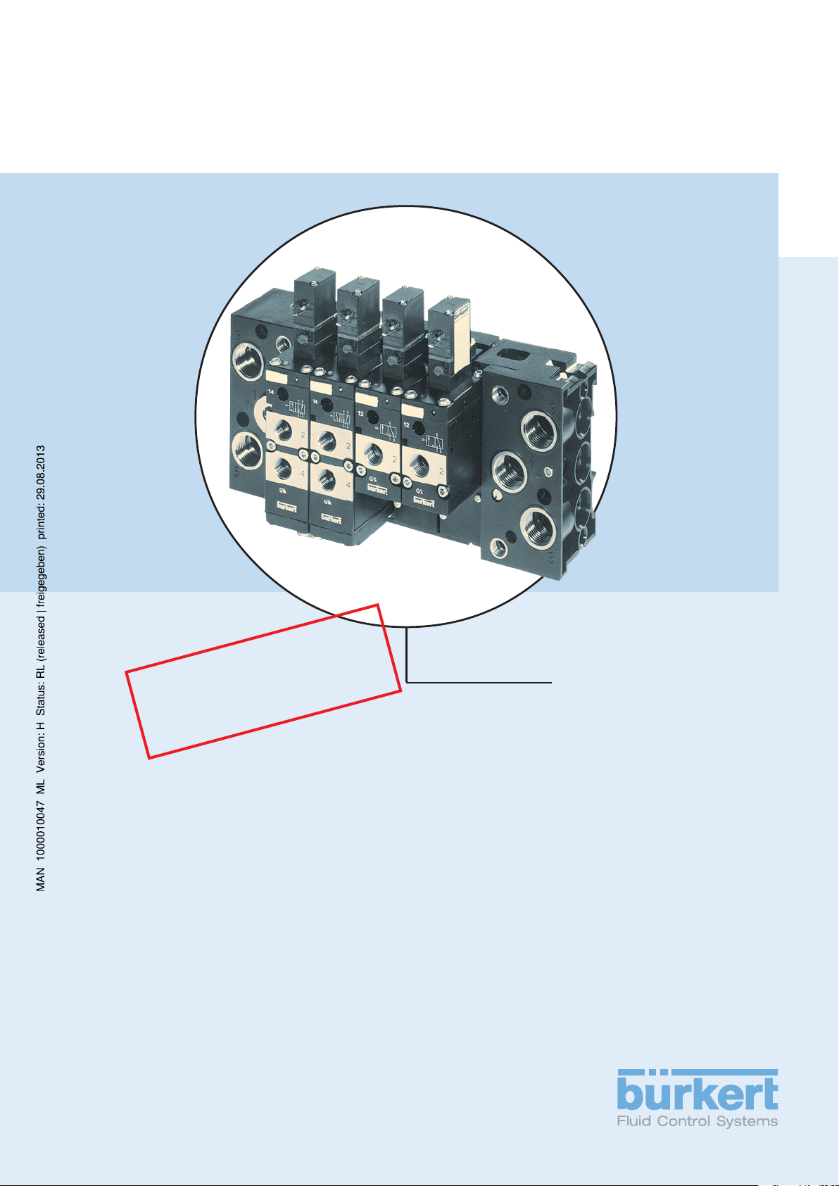
Block Assemblies and Modular Pneumatic
pneumatische Grundschiene Typ MP07
Blocs multiples et Profil pneumatique
Type 6516 / 6517
Basic Rail Type MP07
Mehrfachblöcke und modulare,
modulaire Type MP07
We reserve the right to make technical changes without notice.
Technische Änderungen vorbehalten.
Sous resérve de modification techniques.
© 2000 Bürkert Werke GmbH & Co. KG
Operating Instructions 0512/11_EU-ML_00803141
Contents of the
Voltage 12V or 24V
UL / UR valid with
class 2 power supply only
Operating Instructions for the
Block Assemblies
Type 6516/6517
and Modular Pneumatic
Basic Rail Type
Typ MP07
GENERAL NOTES.................................................................................................................................................................................................................................. 3
Symbols ..................................................................................................................................................................................................................................................... 4
Safety notes
Warranty conditions
.......................................................................................................................................................................................................................................... 4
.................................................................................................................................................................................................................... 5
TECHNICAL DESCRIPTION ................................................................................................................................................................................................ 7
Valve Construction....................................................................................................................................................................................................................... 8
Valve operations of the Type 6516 / 6517
Media
Electrical connections
Example of a block assembly
............................................................................................................................................................................................................................................................ 9
.............................................................................................................................................................................................................. 9
.................................................................................................................................................................................... 10
...................................................................................................................................................... 8
INSTALLATION, INITIALISATION AND SERVICE........................................................................................................................... 11
General notes................................................................................................................................................................................................................................. 12
Setting up block assemblies using the modular pneumatic rail
type MP07
Dismantling the module
Other possible uses of the connecting module, - right-hand -
Mounting the valve block
........................................................................................................................................................................................................................................... 12
..................................................................................................................................................................................................... 13
......................................................................................... 13
.................................................................................................................................................................................................. 13
Mounting single valves
Measures to be taken before putting into service
Faults
......................................................................................................................................................................................................................................................... 16
....................................................................................................................................................................................................... 15
............................................................................................................................ 16
6516 / 6517 - 1

C
ONTENTS
english
2 - 6516 / 6517

Symbols ..................................................................................................................................................................................................................................................... 4
Safety notes
.......................................................................................................................................................................................................................................... 4
Warranty conditions
.................................................................................................................................................................................................................... 5
6516 / 6517 - 3
G
ENERAL NOTES
In these Operating Instructions, the following symbols are used:
indicates a working step that you will have to carry out
english
ATTENTION!
NOTE
To ensure that the device will function correctly, and have a long service life, please comply with the
information in these Operating Instructions, as well as with the application conditions and additional
data given in the Type 6516 and 6517 data sheets:
• When planning the application of the device, and during its operation, observe the general technical
rules!
• Note that lines and valves must not be unscrewed from systems that are under pressure!
• Observe the relevant accident prevention and safety regulations applicable for electrical equipment
throughout the operation, maintenance and repair of the device!
indicates information which must be followed. Failure to do this could endanger your
health or the functionality of the device.
indicates important additional information, tips and recommendations.
• Always switch off the voltage supply before working on the system!
• Take suitable measures to prevent unintentional operation or impermissible impairment!
• If these instructions are ignored, no liability will be accepted from our side, and the guarantee on the
device and on accessories will become invalid!
NOTE
If there are discrepancies, please contact immediately your Bürkert subsidiary or our customer service.
Approvals such as Ex, UL, UR, CSA, DVGW etc., will be indicated on the rating plate,
or by a special label.
Bürkert Steuer- und Regelungstechnik, Service-Abteilung
Chr.-Bürkert-Str. 13-17, D-76453 Ingelfingen
Tel.: (07940) 10-111
Fax: (07940) 10-448
eMail: info@de.buerkert.com
4 - 6516 / 6517
Warranty conditions
This document contains no warranty statements. In this connection we refer to our general sales and
business conditions. A prerequisite for validity of the warranty ist unse of the device as intended with
observance of the specified conditions of use.
G
ENERAL NOTES
ATTENTION!
The warranty covers only faultless condition of the Block Assemblies Type 6516,
6517 and Modular Pneumatic Basic Rails Type MP07. No liability will be accepted
for consequent damage of any kind that max arise form failure or malfunctioning of
the device.
english
6516 / 6517 - 5
G
ENERAL NOTES
english
6 - 6516 / 6517

T
ECHNICAL DESCRIPTION
TECHNICAL
DESCRIPTION
Valve Construction....................................................................................................................................................................................................................... 8
Valve operations of the Type 6516 / 6517
Media
Electrical connections
Example of a block assembly
............................................................................................................................................................................................................................................................ 9
.............................................................................................................................................................................................................. 9
.................................................................................................................................................................................... 10
.................................................................................................................................................. 8
english
6516 / 6517 - 7
T
ECHNICAL DESCRIPTION
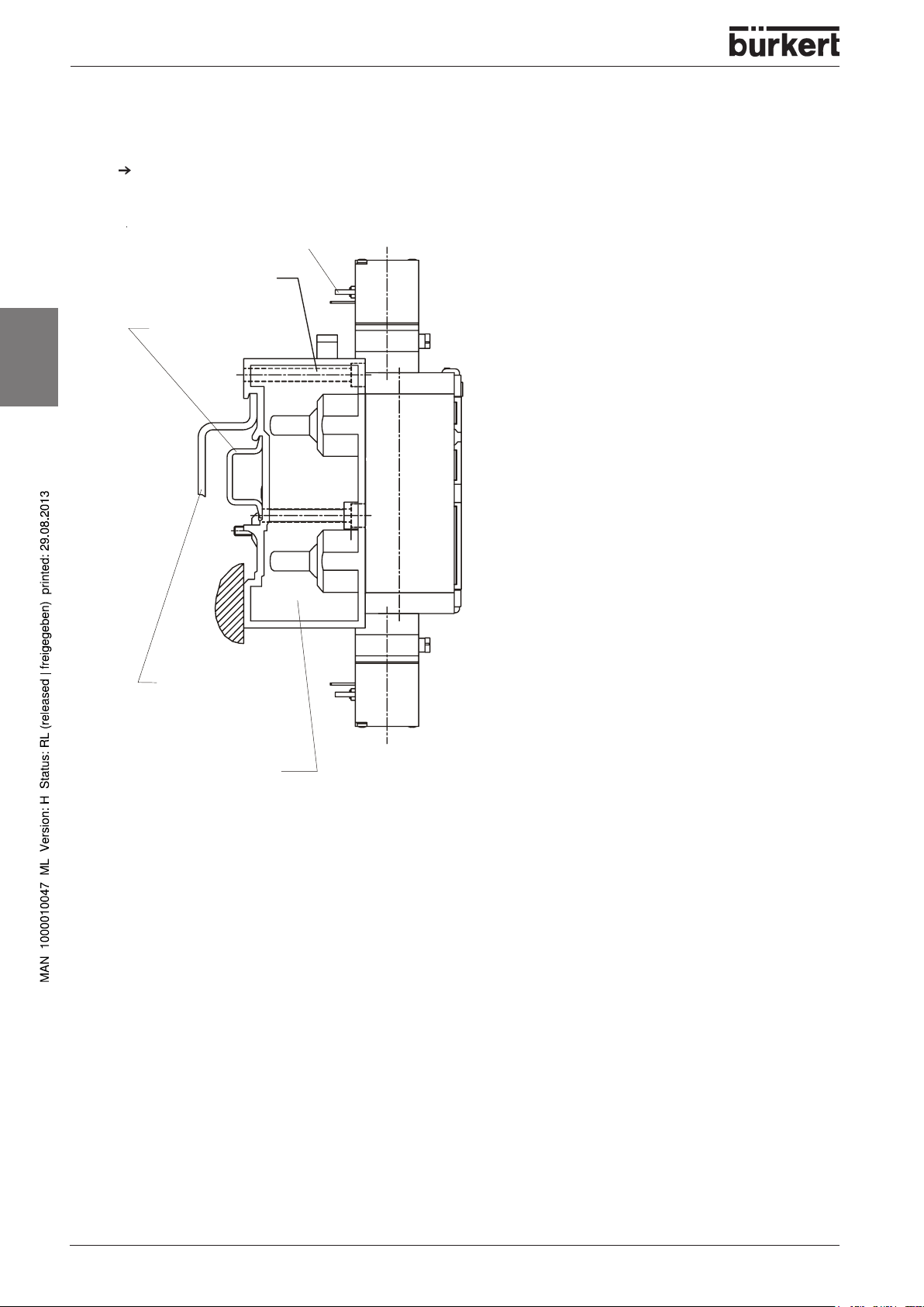
Valve Construction
• 3/2 way pilot valve with various electrical connection possibilities
• valve body with diaphragm and seat seals (3/2 and 5/2), or with gate valve (5/3)
• 2(B) / 4 (A) service ports plus supply and venting ports 1 (P) / 3 (R) / 5 (S) with
internal G 1/4 thread
• as option, plug-in connectors for external 8 mm hose diameters for the service ports
• the valves can be mounted on the modular pneumatic basic rail Type MP07
• can be mounted in any position, preferably with the magnetic system at the top
NOTE
english
Plug-in connections only for the service ports 2 (B) and 4 (A).
The valves require no maintenance.
Valve operations of the Type 6516 / 6517
3/2 way valve:
In de-energised position, Pressure Inlet 1 closed, Outlet Port 2 exhausted
3/2 way valve for vacuum, with auxiliary pilot air:
In de-energised position, Pressure Inlet 1 closed, Outlet Port 2 exhausted
ATTENTION!
The vacuum generator must be connected to port 1!
3/2 way valve:
In de-energised position, Pressure Inlet 1 connected to Outlet Port 2
5/2 way valve:
In de-energised position, Pressure Inlet 1 connected to Outlet Port 2, Outlet Port 4 exhausted.
5/2 way valve:
Impulse drive model
8 - 6516 / 6517
5/3 way valve:
in middle position, all outlet ports closed
5/3 way valve:
in middle position, Outlet Ports 2 and 4 vented, Pressure Inlet 1 closed
T
ECHNICAL DESCRIPTION
Media
• filtered compressed air (max. particle size 10 µm), preferably non-oiled
• operation is possible with oiled air
• seal materials: BP = NBR and polyurethane for 3/2 and 5/2 valves
• permissible medium temperature: max. +50° C
• permissible ambient temperature: max. +55° C
• operational pressure range: 2 - 8 bar
NOTE
ATTENTION!
BB = NBR and POM for 5/2 pulse and 5/3 valves
The pilot pressure of the pneumatic controller is dependent on the pressure of the flow
of medium: it must not exceed a maximum of 8 bar!
Observe the permissible pressure range given on the rating plate!
Pressure difference between Ports 1 and 3/5
≥ ≥
≥ 2 bar
≥ ≥
english
Electrical connections
• read the voltage, electrical power, type of protection and current from the rating plate!
• voltage tolerance ±10%
• electrical connection: Instrument socket type 2506 to the tag connection on the coil (tightening
torque: 1 Nm)
• protection level IP 65 (only in combination with appliance socket type 2506)
• to match the cable run, the instrument socket can be mounted rotated by 180°
• refer to types 6106 or 8640 for other connection possibilities
ATTENTION!
When screwing down the instrument socket onto the coil,
ensure that the flat seal is well seated!
6516 / 6517 - 9
T
ECHNICAL DESCRIPTION
english
r
o
t
a
c
i
t
h
g
i
r
,
e
l
u
d
o
m
on
i
-
e
l
b
u
o
d
e
l
u
d
o
m
e
s
a
B
-
t
h
g
i
r
,
e
l
u
d
o
m
n
o
i
t
c
e
n
e
l
p
i
r
t
e
l
u
d
o
m
e
s
a
B
h
c
t
a
c
g
n
i
k
c
o
L
-
t
f
e
l
,
e
l
u
d
o
m
n
o
i
t
c
e
n
n
o
C
n
o
C
k
o
o
h
g
n
i
k
c
o
L
l
e
n
n
a
h
c
y
l
p
p
u
S
t
c
e
n
n
o
C
g
n
i
R
O
t
e
k
s
a
g
e
l
i
f
o
r
P
d
n
i
e
r
u
s
s
e
r
P
t
n
e
v
e
v
l
a
v
t
o
l
i
P
Example of a block assembly
10 - 6516 / 6517
m
x
N
a
5
m
,
1
I
NSTALLATION
, I
NITIALISATION AND SERVICE
INSTALLATION,
INITIALISATION
AND SERVICE
General notes................................................................................................................................................................................................................................. 12
Setting up block assemblies using the modular pneumatic rail
type MP07
Dismantling the module
Other possible uses of the connecting module, - right hand -
Mounting the valve block
Mounting single valves
Measures to be taken before putting into service
........................................................................................................................................................................................................................................... 12
..................................................................................................................................................................................................... 13
......................................................................................... 13
.................................................................................................................................................................................................. 13
....................................................................................................................................................................................................... 15
............................................................................................................................ 16
english
Faults
......................................................................................................................................................................................................................................................... 16
6516 / 6517 - 11
I
NSTALLATION
, I
NITIALISATION AND SERVICE
General notes
Work on the valve should only be carried out by specialist staff and with the correct tools!
Before working on the system, always turn off the supply voltage!
Clean the piping system before installing the valve!
Where necessary, connect a strainer upstream to protect against faults.
When tightening the connections, never use the coil as a lever!
Ensure that the operational conditions agree with the performance data of the unit!
Ensure that the operational conditions agree with the performance data of the unit!
english
ATTENTION!
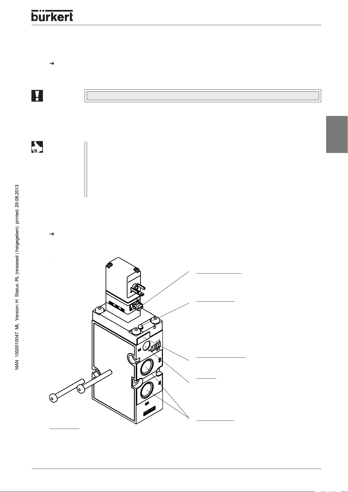
Pressure indicator with indicating pin on the connecting module - right -
- Indicating pin can be pressed in: pressure in valve block < 1 bar
- Indicating pin cannot be pressed in: there is pressure in the valve block
- Indicating pin springs back: there is pressure in the valve block
Lines or valves must never be loosened while the system is under pressure!
Observe the pressure indicator on the right-hand connecting module!
(vent the system before dismantling
lines or devices)
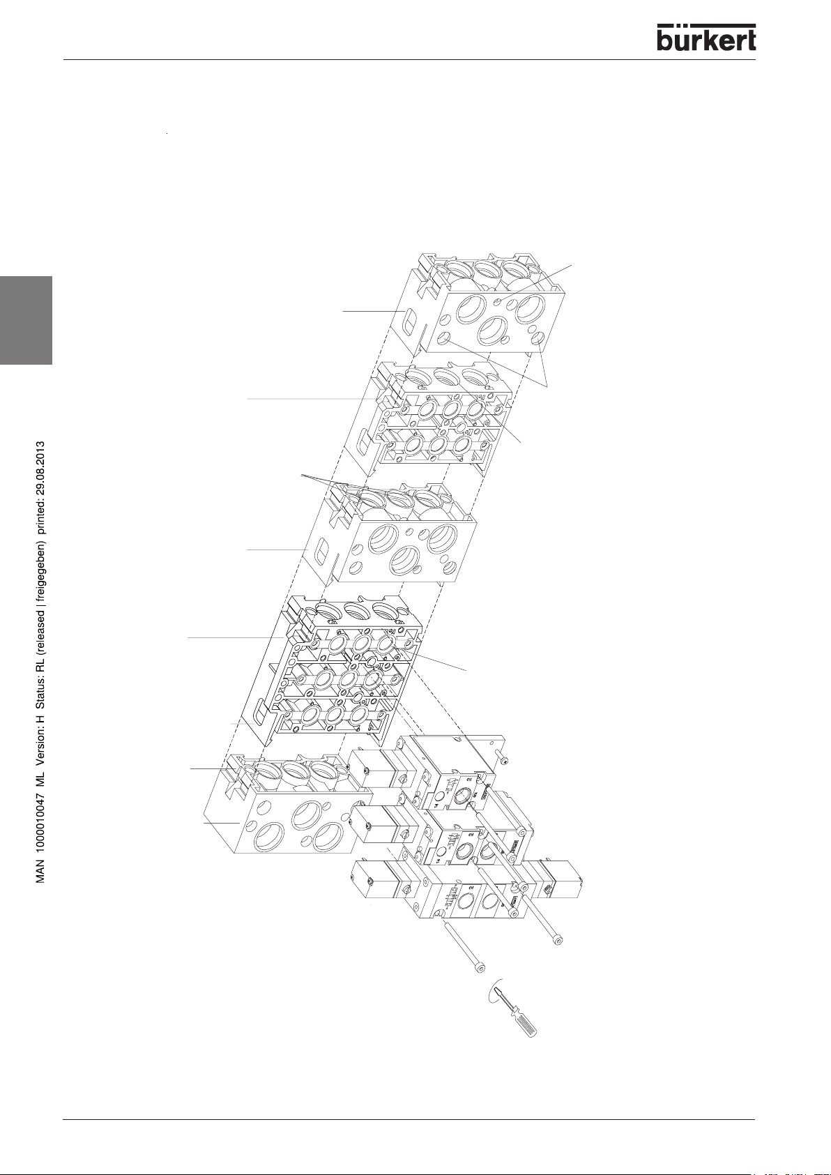
Setting up block assemblies using the modular pneumatic rail
type MP07
With combination of two-way and three-way base modules, you can assemble valve blocks of any size.
NOTE
Check that each module is completely pre-fitted with O-rings!
Before locking together, lightly grease or oil the fitted O-rings.
Insert the hooks of the module being added into the slot on the previous module, ensuring that the O-
rings are correctly seated!
Press the modules together until both hooks latch.
Ensure that the profile gaskets are correctly seated on the base module!
ATTENTION!
12 - 6516 / 6517
It is advisable to start the assembly with the left-most connector module. (Fig. 1).
Squashed O-rings and profile gaskets sause leackages in the block!
I
NSTALLATION
Secure the valves to the base module using 2 M4 screws each.
(Tightening torque max. 1.5 Nm).
Mount the complete valve block onto the wall or the standard rail.
Connect the supply and working lines.
Make the electrical connections to the pilot valves: in doing this, observe the values given on the rating
plate!
, I
NITIALISATION AND SERVICE
Dismantling the module
Unlatch both locking hooks by using a screwdriver on the end dismantling-grooves.
Remove the block part / module sideways.
Other possible uses of the connecting module, - right-hand -
• As a separation module for special applications when building up several pressure levels in a single
block
english
• Additional supply lines for larger valve blocks.
Mounting the valve block
Standard rails
• Standard rail 35 x 15 DIN 50022 (Standard)
• Standard rail 75 x 25 DIN 50023
NOTE
Installation
Hang the valve block onto the upper groove of the standard rail.
Latch the lower clamp into the standard rail.
Firmly tighten the screws on the clamp.
When using the 75 x 25 DIN 50023 standard rail, change over the pre-assembled
screws with clamps and springs as necessary.
Dismounting
Loosen the clamping screws (by about 4 revolutions).
Remove the block upwards from the standard rail.
6516 / 6517 - 13
I
NSTALLATION
english
, I
NITIALISATION AND SERVICE
Wall mounting
Fix the module system directly to the wall using M5 screws.
Electrical connection
can be rotated by 180°
Wall mounting
Standard rail 35 x 15
DIN 50022
Standard rail 75 x 25
DIN 50023
Connecting module
Figure: Mounting the valve block
14 - 6516 / 6517
Mounting single valves
I
NSTALLATION
, I
NITIALISATION AND SERVICE
Fix the single valve directly to the wall using M4 screws.(Figure:
Mounting single valves, Manual override, Pneumatic position indicator
ATTENTION!
When mounting, do not distort the valve body!
Installation, Initialisation and Service -
Plug-in connections
NOTE
For plug-in connections, the hose lines must meet the following requirements:
• Minimum rigidity of 40 Shore D (to DIN 53505 or ISO 868);
• External diameter corresponding to DIN 73378 (max. permissible deviation ± 0.1 mm
from nominal dimension);
• Without burr, cut at right-angles and with undamaged circumference;
• The hose lines must be pushed into the plug-in connectors up to the stop.
Dismantling the plug-in connections
)
english
To release the line, press in the pressure ring and pull out the hose line.
Manual override
to operate the valve manually, turn the manual
override by 90° in the direction of the arrow
Indicating pin for indicating the pneumatic
position
With the valve not switched, the red indicating
pin can be pressed in. If the valve has been
switched, the indicating pin moves outwards,
and remains in this position. The indicating pin
must be pushed in again for every functional
test.
Designation plate (can be removed for
marking / engraving)
Port 14
• not used in the standard model
• used as an auxiliary pilot air connection
and as the connection for pneumatic
controls
Service ports
M4 screws
for wall mounting
the single valve
Figure: Mounting single valve, Manual override, Pneumatic position indicator
2 (B) and 4 (A)
6516 / 6517 - 15
 Loading...