


 Loading...
User Manual for Professional Firmware WZR-HP-AG300H
Nfiniti High Power Wireless Router & Access Point
www.buffalotech.com
35011803 ver.01
1. |
Introduction |
3 |
||
1.1. |
Welcome |
3 |
||
1.2. |
Device Configuration |
3 |
||
|
1.2.1. |
Factory Settings |
3 |
|
2. |
1.2.2. |
Initial Operation |
3 |
|
Configuration via the Web Interface |
4 |
|||
2.1. |
Preparation |
4 |
||
2.2. |
Web Interface Access |
4 |
||
2.3. |
Web Interface Structure |
5 |
||
|
2.3.1. |
Setup |
6 |
|
|
2.3.1.1. Basic Configuration |
6 |
||
|
2.3.1.2. Dynamic DNS (DynDNS or DDNS) |
6 |
||
|
2.3.1.3. MAC Address Cloning |
7 |
||
|
2.3.1.4. Advanced Routing |
7 |
||
|
2.3.1.5. Networking |
7 |
||
|
2.3.1.6. EoIP Tunnel |
8 |
||
|
2.3.2. |
Wireless |
8 |
|
|
2.3.2.1. Basic Settings |
8 |
||
|
2.3.2.2. Wireless Security |
10 |
||
|
2.3.2.3. AOSS/WPS |
11 |
||
|
2.3.2.4. MAC Filter |
12 |
||
|
2.3.3. |
Services |
12 |
|
|
2.3.3.1. Services |
12 |
||
|
2.3.3.2. FreeRadius |
12 |
||
|
2.3.3.3. PPPoE Server |
13 |
||
|
2.3.3.4. VPN |
13 |
||
|
2.3.3.5. USB |
13 |
||
|
2.3.3.6. NAS |
13 |
||
|
2.3.3.7. Hotspot |
14 |
||
|
2.3.3.8. Milkfish SIP Router |
14 |
||
|
2.3.3.9. My Ad Network |
14 |
||
|
2.3.4. |
Security |
14 |
|
|
2.3.4.1. Firewall |
14 |
||
|
2.3.4.2. VPN Pass-through |
14 |
||
|
2.3.5. |
Access Restrictions |
14 |
|
|
2.3.5.1. WAN Access |
14 |
||
|
2.3.6. |
NAT / QoS |
14 |
|
|
2.3.6.1. Port Forwarding |
14 |
||
|
2.3.6.2. Port Range Forwarding |
15 |
||
|
2.3.6.3. Port Triggering |
15 |
||
|
2.3.6.4. UPnP |
15 |
||
|
2.3.6.5. DMZ |
15 |
||
|
2.3.6.6. QoS |
15 |
||
|
2.3.7. |
Administration |
15 |
|
|
2.3.7.1. Management |
15 |
||
|
2.3.7.2. Keep Alive |
16 |
||
|
2.3.7.3. Commands |
16 |
||
|
2.3.7.4. WOL |
16 |
||
|
2.3.7.5. Factory Defaults |
16 |
||
|
2.3.7.6. Firmware Upgrade |
16 |
||
|
2.3.7.7. Backup |
16 |
||
|
2.3.8. |
Status |
16 |
|
|
2.3.8.1. Router |
16 |
||
|
2.3.8.2. WAN |
17 |
||
|
2.3.8.3. LAN |
17 |
||
|
2.3.8.4. Wireless |
17 |
||
|
2.3.8.5. Bandwidth |
17 |
||
|
|
|
- 1 - |
|
3. |
2.3.8.6. SysInfo |
17 |
||
Use Cases |
18 |
|||
3.1. |
Access Point |
18 |
||
|
3.1.1. |
Access Point with NAT / DHCP |
18 |
|
|
3.1.1. |
Access Point attached to a network / Internet gateway |
19 |
|
3.2. |
Wireless Client |
20 |
||
3.3. |
Wireless Client Bridge |
21 |
||
3.4. |
FTP Server |
23 |
||
|
3.4.1. |
Examples |
23 |
|
|
3.4.2. |
Logging into the FTP server |
25 |
|
4. |
3.4.3. |
Common FTP commands |
25 |
|
GPL Statement |
27 |
|||
4.1. |
GNU General Public License |
27 |
||
|
4.1.1. |
Preamble |
27 |
|
4.1.2.GNU General Public License – Terms and Conditions or Copying,
Distribution and Modification |
28 |
|
4.1.3. |
NO WARRANTY |
31 |
Appendix |
Product Warranty Information |
33 |
- 2 -
1. Introduction
1.1.Welcome
This AirStation wireless router comes with two different firmware packages. You may use either the dd-wrt-based Professional firmware or the simple User-friendly firmware. By default, the Professional firmware is preinstalled for US/EU products, and the User-friendly firmware is preinstalled for Asia-Pacific products.
1.2. Device Configuration
From the factory, the router is configured as a network bridge. That means that all network interfaces can communicate with each other using this default bridge. The router is ready to use with a few simple adjustments.
1.2.1.Factory Settings
Because all interfaces are attached to the bridge by default, they all have the same IP configuration:
IP address |
192.168.11.1 |
Subnet Mask |
255.255.255.0 |
DHCP server |
enabled |
DHCP-Range |
192.168.11.2 - 66 |
The Wireless LAN interface is activated by default with an SSID generated from the device’s MAC address. For security, unused interfaces should be disabled. Wireless LAN interfaces that are not disabled should be configured with secure encryption (WPA2 or WPA is recommended) and a secure password.
1.2.2.Initial Operation
Connect your computer to the router with an Ethernet LAN cable and power the router on. It will take about 30 seconds to boot. You can then access it via telnet or web browser at the IP address 192.168.11.1. The DHCP server in the router is enabled by default. If your PC’s Ethernet is configured for DHCP it should receive an IP address from the router’s DHCP server. If not, please configure the Ethernet interface with an address from the 192.168.11.x subnet.
Because all relevant settings can be made using the web interface, this manual refers to configuration via the web GUI only.
- 3 -
2.Configuration via the Web Interface
The router contains an integrated web server that provides an easy to use web interface. It allows configuration, administration, and status checking in a simple but effective way.
When accessing the web GUI for the first time, change the default username and password. By default, the router’s status page can be accessed without authentication, but this can be disabled.
The web interface was successfully tested on the following browsers:
-Internet Explorer 7.x and newer versions
-Firefox 2.x and newer versions
-Safari 2.x and newer versions
2.1.Preparation
Connect your PC to the router and power the router on as described in 1.2.2. After the router has loaded its operating system, you can communicate with it via your LAN network interface.
The easiest way to test if your PC can communicate with the router is to ping 192.168.11.1.
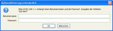
2.2. Web Interface Access
Open a browser window. Enter the address http://192.168.11.1 into the address bar. The status page will be displayed.
When you click on a tab, the login window will pop up. Enter the username and password you previously set.
- 4 -

2.3. Web Interface Structure
- 5 -

2.3.1.Setup
2.3.1.1.Basic Configuration
Setup Assistant
The setup assistant provides a step-by-step interface for basic router configuration. This configures most common settings automatically.
WAN Setup
Here you’ll find the most important settings to configure your internet access and WAN port. DHCP is enabled by default, but you can also use PPPoE, PPTP, L2TP, static IP, or HeartBeat Signal. If you don’t use a password to log in to your ISP, you may need to enter “0000” for the password. Also, for some ISPs you should not enter the service name, as it will prevent establishing the connection. If you experience connection problems, then leave the service name empty.
WAN Connection Type
Disabled
Static IP
Automatic
Configuration - DHCP
PPPoE
PPTP
L2TP
HeartBeat Signal
3G/UMTS
Description
The WAN port is disabled.
A static IP address will be used – enter the IP address, subnet mask, gateway, and server manually.
The router obtains its WAN-side IP address from a DHCP server.
Configure as PPPoE-client. For VDSL, check the “VDSL-Tagging“ box.
Establishes connection via PPTP. Establishes connection via L2TP.
If you use a HeartBeat connection, consult your ISP for setup information. HeartBeat Signal is used only in Australia.
Configures Internet Access via 3G/UMTS. Enable USB in the “Services” section and attach a 3g/UMTS USB stick to the router.
Network Setup
Network Setup configures the router’s basic settings to match the local network. By default these settings are valid for all network ports except the WAN because they are all attached to the default bridge. If ports are disassociated from the bridge they will have different settings.
2.3.1.2.Dynamic DNS (DynDNS or DDNS)
Dynamic DNS allows the assignment of a DNS record to a dynamically assigned WAN-side IP address. A DynDNS client updates DNS records when your WAN-side IP address changes.
The router’s firmware offers presets for the most common DynDNS services plus an option to define individual settings.
- 6 -

DynDNS Service |
|
Description |
Disabled |
Default, no DynDNS |
|
DynDNS.org |
|
|
freedns.afraid.org |
|
|
ZoneEdit.com |
|
|
No-IP.com |
|
|
3322.org |
|
|
easyDNS.com |
|
|
TZO.com |
|
|
DynSIP.org |
|
Individual DynDNS service configuration |
Custom |
|
|
2.3.1.3.MAC Address Cloning
MAC address cloning lets you assign a different MAC address to the router than the one encoded in the hardware.
2.3.1.4.Advanced Routing
Operating Mode
The default operating mode of the router is Gateway. Other routing protocols are available.
Modus |
|
Description |
Gateway |
Gateway (default) |
|
BGP |
|
BGP Routing |
Rip2 Router |
Rip2 Routing |
|
Router |
Router |
|
Static Routing
The Static Routing section lets you add static routes. The input parameters are equivalent to the parameters of the Linux command “route”.
2.3.1.5.Networking
The Networking section allows detailed network configuration.
VLAN Tagging
Use this option to configure VLAN tagging.
Bridging
By default, one bridge (br0) is defined and active. In this section you can define additional bridges and change the interface assignment according to your requirements.
Bonding
- 7 -

Bonding offers the ability to “bond” interfaces together. Bonding can be used to enhance throughput or provide failover capabilities.
Port Setup
The port setup section allows further configuration of the routers network interfaces. Network interfaces can be separated from the bridge and it is possible to assign separate network settings for each interface. If an interface is separated from the bridge, add routing rules to allow communication between the interface and the bridge or other unbridged interfaces.
DHCPD
Besides the default DHCP server, you can define additional DHCP servers.
2.3.1.6.EoIP Tunnel
EoIP (Ethernet over IP) tunnels can transport Ethernet data packages via a tunnel over existing IP connections. You can define up to 10 tunnels that can also be bonded.
2.3.2.Wireless
2.3.2.1.Basic Settings
Each Wireless LAN interface has its own section in the wireless basic settings screen. The wireless interfaces are labelled ath0 and ath0.1
– ath0.4 depending on the number of radios installed. To correctly identify the antenna connectors, please compare the MAC addresses printed on the enclosure with the addresses displayed in the web interface.
Wireless Mode
This parameter is used to define the operating mode of the Wireless LAN interface. You can select among the following modes:
Modus
AP
Client
Client-Bridge
AdHoc
WDS Station
WDS AP
Description
WLAN Access Point mode (default) WLAN Client mode
Client-Bridge mode allows connecting to another Wireless LAN access point and establishing a network bridge with that access point
AdHoc operating mode, required for building mesh networks
WDS Station is the client in a WDS-AP <-> WDS station bridge. This is a special wireless networking mode that offers better flexibility and security than the classical MAC address based WDS.
WDS AP is the AP side for WDS AP <-> WDS Station. A WDS AP allows connections from WDS Stations and Wireless Clients.
- 8 -

Wireless Network Mode
Defines the IEEE802.11 networking mode.
Mode |
|
Description |
|
||
Disabled |
Interface is disabled |
||||
Mixed |
2.4 |
GHz 802.11b |
/ 802.11g / 802.11n mixed |
||
|
|
mode |
|
|
|
A-Only |
|
5 GHz 802.11a mode (802.11b, 802.11g, and |
|||
|
|
802.11n |
devices |
cannot connect) |
|
B-Only |
2.4 |
GHz 802.11b |
mode (802.11a, 802.11g, and |
||
|
|
802.11n |
devices |
cannot connect) |
|
G-Only |
2.4 |
GHz 802.11g |
mode (802.11a, 802.11b, and |
||
|
|
802.11n |
devices |
cannot connect) |
|
BG-Mixed |
2.4 |
GHz 802.11b |
& 802.11g mixed mode (802.11a |
||
|
|
and 802.11n devices cannot connect) |
|||
NA-Mixed |
5 GHz 802.11n & |
802.11a mixed mode (802.11b |
|||
|
|
and 802.11g devices cannot connect) |
|||
NG-Mixed |
2.4 |
GHz 802.11n |
& 802.11g mixed mode (802.11a |
||
|
|
and 802.11b devices cannot connect) |
|||
N-Only (5 GHz) |
5 GHZ 802.11n mode (802.11a, 802.11b, and |
||||
|
|
802.11g |
devices |
cannot connect) |
|
N-Only (2.4 GHz) |
2.4 |
GHZ 802.11n |
mode (802.11a, 802.11b, and |
||
|
|
802.11g |
devices |
cannot connect) |
|
Channel Width
Some wireless network modes support wireless channel widths besides the standard 20 MHz. 802.11g & 802.11n offer the option to use 40 MHz channels for enhanced throughput. Both the AP and the client must support 40 MHz channels to use them.
Wireless Channel (AP only)
Set the desired wireless channel, or let the router choose a free channel automatically. If the router is in classic WDS (MAC address based) mode, then the wireless channel must be selected manually.
Wireless Network Name (SSID)
The name of the wireless network the radio transmits or connects to (depending on the wireless mode)
Wireless SSID Broadcast (AP only)
The name of the wireless network (SSID) may be broadcasted or not. Not broadcasting does not prevent the network from being detected by a wireless network sniffer; it just hides the name.
Advanced Settings
Check this box to get access to advanced wireless settings. These advanced parameters should be only modified by experienced users.
- 9 -
2.3.2.2.Wireless Security
Because wireless data packets can easily be sniffed, wireless connections require a greater level of security to ensure that data cannot be read by unauthorized users.
Security Mode
Mode
Disabled
WPA Personal
WPA Enterprise (AP only)
WPA2 Personal
WPA2 Enterprise (AP only)
WPA2 Personal Mixed
WPA2 Enterprise Mixed (AP only)
RADIUS
WEP
802.1x (Client only)
Description
No encryption set (not recommended!)
WPA encryption with a passphrase (text password)
WPA encryption with Radius Client authentication according to 802.1x
WPA2 encryption with a passphrase (text password)
WPA2 encryption with Radius Client authentication according to 802.1x
WPA & WPA2 encryption in WPA/WPA2 mixed mode with a passphrase (text password)
WPA & WPA2 encryption in WPA/WPA2 mixed with Radius Client authentication according to 802.1x
WEP 64 Bit / 128 Bit encryption (insecure; not recommended!)
Client side mode to connect to AP’s working with WPA Enterprise Modes via RADIUS authentication
When using WEP encryption (not recommended), the user can choose between 64 bit and 128 bit keys. Keys can be entered as passphrases that are used to generate the Hex keys. Theoretically 128 bit keys offer a higher level of security but because of design flaws, that’s not the case in actual use.
Key length |
|
Description |
64 Bit (10 |
|
Standard |
Hexadecimal |
|
|
characters) |
|
|
128 Bit (26 |
|
|
Hexadecimal |
|
|
characters) |
|
|
With WPA or WPA2 encryption, there are several encryption algorithms to choose from. AES is more secure but TKIP is more widely supported. There is also a TKIP + AES setting, but that does not offer more security than TKIP.
Algorithm |
|
Description |
TKIP |
|
TKIP encryption, supported by most clients |
|
- 10 - |
|

AES
TKIP + AES
devices
AES encryption offers a better level of security but might not be supported by a number of client devices and requires less CPU processing power.
Mixed mode – offers best compatibility but doesn’t work in all environments
If RADIUS security is used, the MAC address format has to be set accordingly.
|
RADIUS MAC format |
|
|
Description |
|
options |
|
|
|
|
|
Standard |
||
|
aabbcc-ddeeff |
|||
|
aabbccddeeff |
|
|
|
|
aa:bb:cc:dd:ee:ff |
|
|
|
|
aa-bb-cc-dd-ee-ff |
|
|
|
2.3.2.3.AOSS/WPS
AOSS (AirStation One-touch Secure Setup) is Buffalo Technology’s system to automatically connect wireless clients to an access point. Just press the button on the AirStation, then press the button for the wireless client (which might be in its software). AOSS will connect the wireless devices automatically. AOSS is recommended if all of your wireless devices support it. AOSS can only be used in AP mode.
The WPS is a standard created by the Wi-Fi Alliance. There are two methods of configuration, PBC and PIN. PBC is similar to AOSS. PIN uses a unique PIN code to register the wireless client to the AirStation. If your wireless devices support it, WPS makes configuration simple and automatic.
Enable AOSS
Enables the AOSS Service. When disabled, AOSS cannot be used.
Start AOSS Negotiation
To initiate AOSS, either click the AOSS button in the GUI or hold down the AOSS button on the front of the router for 3 seconds.
Security Modes
You may choose which security modes are offered in the AOSS negotiation process. The use of WEP in general is not recommended due to security concerns.
WPS Button
Enables the WPS button. When disabled, WPS button cannot be used.
WPS PIN
Enter the PIN code printed on your client device or your client authentication application.
- 11 -

2.3.2.4.MAC Filter
The MAC Filter defines a list of client MAC addresses that are allowed to connect wirelessly. MAC addresses that aren’t on the list aren’t allowed to connect.
2.3.3.Services
2.3.3.1.Services
The services section allows the configuration of basic service settings. Telnet and SSH can be configured this way. Remote access options are configured in the Administration section.
|
Available DHCP Server |
|
|
Description |
|
Domains |
|
|
|
|
|
|
Standard |
|
|
WAN |
|
||
|
LAN / WLAN |
|
|
|
|
|
|
|
|
|
Rflow / MACupd |
|
|
Description |
|
Interface Options |
|
Standard |
|
|
LAN & WLAN |
|||
|
LAN |
|
|
|
|
WLAN |
|
|
|
2.3.3.2.FreeRadius
Certain applications (for example, Chillispot hotspot software) benefit from a RADIUS server for management of user credentials and settings.
Server Certificate
This section contains the parameters to generate the RADIUS server certificate. The certificate needs to be generated before clients can be configured to connect to the RADIUS server.
Certificate Status
Displays the server certificate creation status.
Settings
Choose the port that the RADIUS server uses for client communication. The default port is 1812.
Clients
This section is used to define RADIUS clients (required for HotSpot usage).
Users
Lists the users defined in the RADIUS servers. Allows creation and modification of accounts.
- 12 -

2.3.3.3.PPPoE Server
Some applications require a PPPoE server on the router, which can be configured here. The PPPoE server is disabled by default.
2.3.3.4.VPN
The router can also be configured as VPN server or VPN client.
PPTP
When defining the PPTP server’s IP range, avoid overlap with the range of IP addresses handed out by DHCP if DHCP is enabled. The IP range is defined using the following syntax:
xxx.xxx.xxx.<start-ip>-<end-ip>
for example
192.168.1.20-30
Enter client login data follows:
<username> * <password> *
for example
testuser * test *
The encryption options can be set as follows
PPTP server type |
|
Settings |
|
DD-WRT Router |
mppe required (Standard) |
||
Windows PPTP Server |
mppe |
required,no40,no56,stateless or |
|
|
|
mppe |
required,no40,no56,stateful |
OpenVPN
OpenVPN is a powerful and flexible VPN solution. OpenVPN security is based on certificates that cannot created on the router itself. Please refer to OpenVPN’s online documentation for instructions on creating certificates and configuring OpenVPN.
2.3.3.5.USB
The router’s USB port can be used for several purposes. Here the basic and advanced USB parameters are defined. Besides enabling USB and defining the USB hardware standard to use you can also define if printer and storage support for USB shall be enabled.
2.3.3.6.NAS
If USB hard drive support is enabled, you can start the integrated ProFTPd server to share data on an attached hard disk via FTP.
- 13 -
The User/Password data are entered as follows:
<username> * <password> *
for example
testuser * test *
Be careful enabling anonymous login. If anonymous login is enabled, everyone accessing your network has permission to read and write data.
2.3.3.7.Hotspot
Most hotspot software requires a server to store user settings and login information. Please note that Sputnik is a commercial hotspot service that requires an agreement with Sputnik for usage.
2.3.3.8.Milkfish SIP Router
This package is an implementation of the Milkfish SIP router.
2.3.3.9.My Ad Network
Allows the creation of an AnchorFree Hotspot that can be used to create revenue via AnchorFree.
2.3.4.Security
2.3.4.1.Firewall
Aside from enabling and disabling the firewall, you can also set additional filters, block certain network requests for the WAN interface, and manage logs.
2.3.4.2.VPN Pass-through
VPN settings effect how the firewall handles IPSec, PPTP, and L2TP connections. By default, pass-through is enabled. Please note that disabling pass-through will usually prevent you from establishing VPN connections from computers located in your local network to VPN servers on the internet.
2.3.5.Access Restrictions
2.3.5.1.WAN Access
The WAN access settings allow the definition of time and service related access rules.
2.3.6.NAT / QoS
2.3.6.1.Port Forwarding
Port forwarding allows the assigning of WAN ports to specific internal IP addresses and matching ports. Bidirectional external traffic can be
- 14 -
forwarded to specific internal devices and computers. Each port forwarding entry defines a source port and a target IP address.
Before adding or removing a port forwarding entry, save all changed settings. Any changes not saved will be lost when a port forwarding entry is added or deleted.
2.3.6.2.Port Range Forwarding
Port range forwarding works similarly to port forwarding. Unlike port forwarding, instead of a single port, a range of ports is forwarded to the same range of ports at the internal target IP address.
2.3.6.3.Port Triggering
Port triggering is a kind of port range forwarding where outgoing traffic on specific ports enables previously defined port forwards for the activating device. This temporarily opens required ports when specific applications are opened on computers on the LAN. This offers a greater level of security than port forwarding or port range forwarding because the ports are only opened when needed.
2.3.6.4.UPnP
UPnP allows UPnP capable applications and devices to open and close required ports automatically as needed. This is simple to use and does not require further configuration steps.
2.3.6.5.DMZ
A DMZ computer is a special computer in the internal network that gets all incoming traffic forwarded. The task of that computer is managing this traffic. When the DMZ feature is activated the internal firewall is activated. This can pose a security issue if not handled with care. Furthermore, several services of the router, that have to be accessible from the WAN side, will not work because the associated traffic is forwarded to the DMZ computer.
2.3.6.6.QoS
QoS (Quality of Service) is a procedure to prioritise network traffic by application. Specific services can be assigned specific bandwidth.
Aside from upstream and downstream bandwidth, you can define settings for specific services and IP and MAC address ranges.
2.3.7.Administration
2.3.7.1.Management
The Management section contains settings for remotely accessing the router and other basic settings that are usually not changed. The settings for the language used in the Web GUI are also located here. You may choose between Chinese (simplified & traditional), Croatian, Dutch, French, German, Hungarian, Italian, Japanese, Latvian, Polish,
- 15 -
Portuguese, Romanian, Russian, Slovenian, Spanish, and Swedish. The default setting is English.
Before using Telnet or SSH, activate the associated service(s) in this section.
2.3.7.2.Keep Alive
Keep-Alive lets you configure monitoring options that automatically reboot the router if a service malfunction causes it to fail to respond.
2.3.7.3.Commands
Entering Linux commands is one of the most powerful ways to access the router’s functionality. This enables you to access services and configure options that are not accessible via the Web GUI. Using shell commands can lead to unexpected results. Use them with utmost care.
Aside from executing the shell commands directly you can also save custom start up and firewall scripts.
2.3.7.4.WOL
With Wake-on-LAN, you can send special data packets to compatible devices on your LAN, causing them to exit sleep mode.
WOL data packets can be triggered manually or scheduled automatically.
2.3.7.5.Factory Defaults
With this feature you can reset the router’s settings to factory defaults. After a reset, the router will restart.
2.3.7.6.Firmware Upgrade
The firmware upgrade option can be used to install a different firmware version. When doing this you can choose if the router’s settings will be restored to factory defaults or kept.
2.3.7.7.Backup
You can use this feature to store your current configuration into a backup file, or to restore from a previously stored configuration. This also makes it simple to set up a number of routers with the exact same configuration.
2.3.8.Status
2.3.8.1.Router
The status screen displays information about the router, such as cpu load, memory consumption, and currently active IP connections. Status is updated automatically.
- 16 -
2.3.8.2.WAN
If the WAN interface is enabled, this screen displays WAN settings and throughput statistics.
2.3.8.3.LAN
Here you can find LAN-related information like active clients and DHCP clients.
2.3.8.4.Wireless
The wireless LAN status screen displays the current wireless LAN interface configuration, wireless LAN clients (in AP modes), and access points (in client modes). If there’s more than one wireless LAN interface, you can switch between them via the interface pull down menu.
2.3.8.5.Bandwidth
Bandwidth monitoring displays real time diagrams for incoming and outgoing traffic for each network interface.
2.3.8.6.SysInfo
The SysInfo screen combines the most important information of the other status pages. By default, the SysInfo page can be accessed from LAN devices without authentication. That can be changed in the
Management section of the Administration area.
- 17 -
3.Use Cases
The following use cases relate to the most commonly used router configurations. The related router configuration is explained step by step.
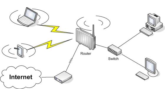
3.1. Access Point
Access Point (AP, sometimes also called “Infrastructure Mode”) is the mode where the router is also the central wireless hub that connects to the LAN and provides access to wireless devices. These wireless clients of the AP can communicate with each other and with wired devices on the network such as the Internet.
Connect your computer to the router as described in 2.1. and access the web interface according to 2.2.
3.1.1.Access Point with NAT / DHCP
Setup -> Basic Setup
WAN Setup
oIn ”Connection Type”, choose the type of WAN connection you want to use and complete the related settings.
Network Setup
oEnter the desired LAN IP address for the router into “Router IP“.
oSet “DHCP Type“ to “DHCP Server“ (this is the default).
o“Enable“ DHCP Server (this is the default).
oAdjust the DHCP address range to match your requirements.
Time Settings
o Choose your time zone.
Click “Save“.
Wireless -> Basic Settings
- 18 -
Enter your country in “Regulatory Domain”
In the “Antenna Gain“ field, please enter the gain of the antenna on your router. The firmware will adjust the transmit power accordingly to meet regulatory requirements. Please keep in mind that very long cables can dampen the HF signal thus reducing the usable antenna gain.
Configure “Wireless Mode“ to “AP“
Set your desired wireless mode in “Wireless Network Mode“. Please note that mixed modes will lead to reduced performance because of maintaining compatibility.
Enter a name for your wireless network into “Wireless Network Name (SSID)”
Click “Save“
Wireless -> Wireless Security
Choose and configure a security mode. Please note that WEP is insecure and should only be used if no other option is available.
Click “Apply Settings“
You can now connect the router to the Internet and your local network. After you successfully connect wireless devices, they will then be displayed on the “SysInfo” and “WLAN Status” pages.
3.1.1.Access Point attached to a network / Internet gateway
Setup -> Basic Setup
WAN Setup
oFor “Connection Type“, choose “Disabled”.
Network Setup
oEnter the desired LAN-side IP address for the router into “Router IP“.
o Set the “DHCP Type“ to “DHCP Server“ (this is the default).
o“Disable” “DHCP Server“.
Time Settings
o Choose your time zone.
Click “Save“.
Wireless -> Basic Settings
Enter your country in “Regulatory Domain”
In the “Antenna Gain“ field, please enter the gain of the antenna on your router. The firmware will adjust the transmit power accordingly to meet regulatory requirements. Please keep in mind that very long cables can dampen the HF signal thus reducing the usable antenna gain.
Configure “Wireless Mode“ to “AP“
Choose a wireless mode in “Wireless Network Mode“. Please note that mixed modes will lead to reduced performance because of maintaining compatibility.
-19 -
Enter a name for your wireless network into “Wireless Network Name (SSID)”.
Click “Save“.
Wireless -> Wireless Security
Choose and configure your desired security mode. Please note that WEP is insecure and should only be used if no other option is available.
Click “Apply Settings“
You can now connect the router to the Internet and your local network. If you’re running a DHCP server in your LAN, connected wireless devices will get their IP addresses from the server.
3.2. Wireless Client
The router can be also used as a wireless LAN client. This can be useful if you want to connect devices to your wireless LAN that do not have a wireless LAN interface. In this configuration, the wireless LAN interface acts as a wireless client. Attached wired Ethernet devices can also access the WAN through the wireless connection.
Setup -> Basic Setup
WAN Setup
oSet “Connection Type“ to “DHCP” to have the AirStation get its IP address from a DHCP server, or to a “Static IP“ if no DHCP server is available.
Network Setup
oEnter the desired LAN-side IP address for the router in “Router IP“.
o Set the “DHCP Type“ to “DHCP Server“ (this is the default setting). o “Enable” “DHCP Server“ (this is the default setting).
oAdjust the DHCP address range to match your requirements.
-20 -
Time Settings
o Choose your time zone.
Click “Save“.
Wireless -> Basic Settings
Enter your country in “Regulatory Domain”
In the “Antenna Gain“ field, please enter the gain of your AirStation’s antenna. The firmware will adjust the transmit power automatically to meet regulatory requirements. Please note that the use of a long extension cable for your antenna will reduce the usable antenna gain.
Configure “Wireless Mode“ to “Client“.
Configure “Wireless Network Mode” to match the capabilities of the access point you want to connect to.
Enter the network name (SSID) of the AP you want to connect to into “Wireless Network Name (SSID)”.
Click “Save“.
Wireless -> Wireless Security
Configure the security mode to match the security settings of the access point you want to connect to.
Click “Apply Settings“.
After the router reboots, please confirm that it has connected to the access point. If there is a DHCP server available on the access point side, and the router is configured to request an IP address, then it should receive an IP address for its WAN-side interface.
You can now either connect wired clients to the access point or configure another wireless network interface as an access point to grant access to wireless clients.
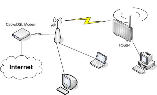
3.3. Wireless Client Bridge
A wireless client bridge offers the ability to transparently integrate the router’s LAN into a different LAN that another access point is connected to. Clients connected to such a router can access devices in both LANs and vice versa. In that configuration the router’s WAN interface is disabled.
- 21 -
Setup -> Basic Setup
WAN Setup
oChoose “Disabled” for “Connection Type” (this will be set automatically).
Network Setup
oEnter the desired LAN-side IP address for the router into “Router IP”.
o“Disable“ “DHCP Server”.
Time Settings
o Choose your time zone.
Click “Save”.
Wireless -> Basic Settings
Enter your country in “Regulatory Domain”.
In the “Antenna Gain” field, please enter the gain of your AirStation’s antenna. The firmware will adjust the transmit power automatically to meet regulatory requirements. Please note that the use of a long extension cable for your antenna will reduce the usable antenna gain.
Configure “Wireless Mode” to “Client Bridge”.
Set “Wireless Network Mode” to match the access point you want to connect to.
Enter the network name (SSID) of the AP you want to connect to.
Click “Save”.
Wireless -> Wireless Security
Configure security to match the security settings of the access point you want to connect to.
Click “Apply Settings”.
After the router reboots, please confirm that it has connected to the access point. If there is a DHCP server available on the access point
- 22 -
side, a pc in the router’s LAN configured to request an address from DHCP should receive an IP address.
3.4. FTP Server
The router can be used as an FTP server when a USB disk (such as a hard disk or flash memory device) is connected to the USB port on the rear of the router.
3.4.1.Examples
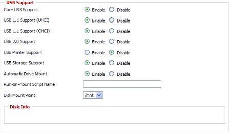
Services -> USB
Make the settings in the USB Support section, and click [Apply
Settings].
Examples:
Core USB Support |
Enabled |
USB 1.1 Support |
Enabled |
(UHCI) |
|
USB 1.1 Support |
Enabled |
(OHCI) |
|
USB 2.0 Support |
Enabled |
USB Storage |
Enabled |
Support |
|
Automatic Drive |
Enabled |
Mount |
|
Run-on-mount |
blank |
Script Name |
|
Disk Mount Point |
/mnt |
- 23 -
Connect a USB disk to the router.
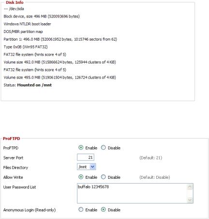
After a short wait, the disk information is displayed in the Disk Info section.
Services -> NAS
Make the settings in the ProFTPD section, and click [Apply Settings].
Setting example: |
|
|
|
ProFTPD |
Enable |
|
Server Port |
21 |
|
Files Directory |
/mnt |
|
Allow Write |
Enable |
|
User Password List |
buffalo |
|
|
12345678 |
|
Anonymous Login |
Disable |
|
(Read-only) |
|
*The user name (example: buffalo) and password (example: 12345678) are separated by a space.
- 24 -
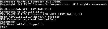
3.4.2.Logging into the FTP server
Open a command prompt window.
Enter “ftp 192.168.11.1” to access the FTP server.Enter the user name, and press the Enter key.Enter the password, and press the Enter key.
When the login is successful, “ftp>” appears on the screen.To logout, enter the “bye” command.
3.4.3.Common FTP commands
|
|
|
|
Command |
Description |
Entry example |
|
ftp |
Starts FTP |
ftp |
|
ls |
Displays |
a list of |
ls |
|
the remote |
|
|
|
directory’s files |
|
|
pwd |
Displays |
the |
pwd |
|
current directory |
|
|
|
on the remote |
|
|
|
computer |
|
|
cd |
Changes the current |
cd img |
|
|
working directory |
|
|
|
on the remote |
|
|
|
computer |
|
|
mkdir |
Creates a remote |
mkdir test |
|
|
directory |
|
|
rmdir |
Deletes a remote |
rmdir test |
|
|
directory |
|
|
lcd |
Changes the current |
lcd E:\test |
|
|
working directory |
|
|
|
on the local |
|
|
|
computer |
|
|
asc |
Switches |
to ASCII |
asc |
|
transfer |
mode |
|
bin |
Switches |
to binary |
bin |
|
transfer |
mode |
|
put |
Uploads a file to |
put test.pdf |
|
|
the remote computer |
|
|
mput |
Uploads multiple |
mput test1.jpg |
|
|
files to |
the remote |
test2.jpg |
|
computer |
|
test3.jpg |
get |
Downloads a file to |
get index.html |
|
|
the local computer |
|
|
mget |
Downloads multiple |
mget test1.jpg |
|
|
files to |
the local |
test2.jpg |
|
computer |
|
test3.jpg |
|
- 25 - |
|
|
|
|
|
delete |
Deletes a file on |
delete |
|
the remote computer |
test1.jpg |
mdelete |
Deletes multiple |
mdelete |
|
files on the remote |
test1.jpg |
|
computer |
test2.jpg |
|
|
test3.jpg |
rename |
Renames a file on |
rename |
|
the remote computer |
test1.jpg |
|
|
new1.jpg |
help |
Displays the Help |
help |
|
for FTP commands |
|
bye |
Exits FTP |
bye |
- 26 -
4.GPL Statement
The firmware that is used in this product includes software that is subject to the GNU Public Licence (GPL)/the GNU Lesser Public Licence (LGPL). To the extent that it is applicable within the context of the GPL and the LGPL, the conditions of the GPL and the LGPL, as well as the relevant source codes, are available from the manufacturer. The code underlying the GPL/LGPL for the software shall be provided, without any ensuing warranty or liability claims. Please see the conditions of the GPL/LGPL for further details.
4.1. GNU General Public License
Version 2, June 1991
Copyright (C) 1989, 1991 Free Software Foundation, Inc. 51 Franklin Street, Fifth Floor, Boston, MA 02110-1301, USA
Everyone is permitted to copy and distribute verbatim copies of this license document, but changing it is not allowed.
4.1.1.Preamble
The licenses for most software are designed to take away your freedom to share and change it. By contrast, the GNU General Public License is intended to guarantee your freedom to share and change free software--to make sure the software is free for all its users. This General Public License applies to most of the Free Software Foundation's software and to any other program whose authors commit to using it. (Some other Free Software Foundation software is covered by the GNU Library General Public License instead.) You can apply it to your programs, too.
When we speak of free software, we are referring to freedom, not price. Our General Public Licenses are designed to make sure that you have
the freedom to distribute copies of free software (and charge for this service if you wish), that you receive source code or can get it if you want it, that you can change the software or use pieces of it in new free programs; and that you know you can do these things.
To protect your rights, we need to make restrictions that forbid anyone to deny you these rights or to ask you to surrender the rights. These restrictions translate to certain responsibilities for you if you distribute copies of the software, or if you modify it.
For example, if you distribute copies of such a program, whether gratis or for a fee, you must give the recipients all the rights that you have. You must make sure that they, too, receive or can get the source code. And you must show them these terms so they know their rights.
We protect your rights with two steps: (1) copyright the software, and
(2) offer you this license which gives you legal permission to copy, distribute and/or modify the software.
Also, for each author's protection and ours, we want to make certain that everyone understands that there is no warranty for this free
- 27 -
software. If the software is modified by someone else and passed on, we want its recipients to know that what they have is not the original, so that any problems introduced by others will not reflect on the original authors' reputations.
Finally, any free program is threatened constantly by software patents. We wish to avoid the danger that redistributors of a free program will individually obtain patent licenses, in effect making the program proprietary. To prevent this, we have made it clear that any patent must be licensed for everyone's free use or not licensed at all.
The precise terms and conditions for copying, distribution and modification follow.
4.1.2. GNU General Public License – Terms and Conditions or Copying, Distribution and Modification
0. This License applies to any program or other work which contains a notice placed by the copyright holder saying it may be distributed under the terms of this General Public License. The "Program", below, refers to any such program or work, and a "work based on the Program" means either the Program or any derivative work under copyright law: that is to say, a work containing the Program or a portion of it, either verbatim or with modifications and/or translated into another language. (Hereinafter, translation is included without limitation in the term "modification".) Each licensee is addressed as "you".
Activities other than copying, distribution and modification are not covered by this License; they are outside its scope. The act of running the Program is not restricted, and the output from the Program is covered only if its contents constitute a work based on the Program (independent of having been made by running the Program). Whether that is true depends on what the Program does.
1. You may copy and distribute verbatim copies of the Program's source code as you receive it, in any medium, provided that you conspicuously and appropriately publish on each copy an appropriate copyright notice and disclaimer of warranty; keep intact all the notices that refer to this License and to the absence of any warranty; and give any other recipients of the Program a copy of this License along with the Program.
You may charge a fee for the physical act of transferring a copy, and you may at your option offer warranty protection in exchange for a fee.
2. You may modify your copy or copies of the Program or any portion of it, thus forming a work based on the Program, and copy and distribute such modifications or work under the terms of Section 1 above, provided that you also meet all of these conditions:
a)You must cause the modified files to carry prominent notices stating that you changed the files and the date of any change.
b)You must cause any work that you distribute or publish, that in whole or in part contains or is derived from the Program or any part
-28 -
thereof, to be licensed as a whole at no charge to all third parties under the terms of this License.
c) If the modified program normally reads commands interactively when run, you must cause it, when started running for such interactive use in the most ordinary way, to print or display an announcement including an appropriate copyright notice and a notice that there is no warranty (or else, saying that you provide a warranty) and that users may redistribute the program under these conditions, and telling the user how to view a copy of this License. (Exception: if the Program itself is interactive but does not normally print such an announcement, your work based on the Program is not required to print an announcement.)
These requirements apply to the modified work as a whole. If identifiable sections of that work are not derived from the Program, and can be reasonably considered independent and separate works in themselves, then this License, and its terms, do not apply to those sections when you distribute them as separate works. But when you distribute the same sections as part of a whole which is a work based on the Program, the distribution of the whole must be on the terms of this License, whose permissions for other licensees extend to the entire whole, and thus to each and every part regardless of who wrote it.
Thus, it is not the intent of this section to claim rights or contest your rights to work written entirely by you; rather, the intent is to exercise the right to control the distribution of derivative or collective works based on the Program.
In addition, mere aggregation of another work not based on the Program with the Program (or with a work based on the Program) on a volume of a storage or distribution medium does not bring the other work under the scope of this License.
3. You may copy and distribute the Program (or a work based on it, under Section 2) in object code or executable form under the terms of Sections 1 and 2 above provided that you also do one of the following:
a)Accompany it with the complete corresponding machine-readable source code, which must be distributed under the terms of Sections 1 and 2 above on a medium customarily used for software interchange; or,
b)Accompany it with a written offer, valid for at least three years, to give any third party, for a charge no more than your cost of physically performing source distribution, a complete machine-readable copy of the corresponding source code, to be distributed under the terms of Sections 1 and 2 above on a medium customarily used for software interchange; or,
c)Accompany it with the information you received as to the offer to distribute corresponding source code. (This alternative is allowed only for non-commercial distribution and only if you received the program in object code or executable form with such an offer, in accord with Subsection b above.)
-29 -
Loading...