

Page 1

Rotavapor® R-220 EX
Operation Manual
096987K en
Page 2

Imprint
Product Identification:
Operation Manual (Original), Rotavapor® R-220 EX
096987K en
Publication date: 02.2018
BÜCHI Labortechnik AG
Meierseggstrasse 40
Postfach
CH-9230 Flawil 1
E-Mail: quality@buchi.com
BUCHI reserves the right to make changes to the manual as deemed necessary in the light of experience; especially in respect to structure, illustrations and technical detail.
This manual is copyright. Information from it may not be reproduced, distributed, or used for competitive purposes,
nor made available to third parties. The manufacture of any component with the aid of this manual without prior
written agreement is also prohibited.
Page 3

3
Rotavapor R-220 EX
Table of Contents
Table of Contents
Read this Operating Manual through carefully
before using the Rotavapor R-220 EX.
Always keep these Instructions readily available in the immediate vicinity of the unit so
that they make be consulted at any time.
Chapter 2 contains important safety rules
which must be ob served to ensure the safe
operation of the rotary evaporator.
1 Scope of Delivery 4
2 Safety 5
3 Function 10
3.1 Principle of Operation 10
4 Putting into Operation 11
4.1 Installation Location 11
4.2 Unpacking 11
4.3 Connecting to the Source of Energy 12
4.4 Setting up the Support Rod 12
4.5 Attachment of the EasyClamp 13
4.6 Removal of the EasyClamp 13
4.7 Installation of the Reflux Glass Assembly 14
4.8 Installation of the Downgrade Glass Assembly 15
4.9 Installation of the Downgrade Glass Assembly
with a 2nd Cooler 16
4.10 Installation of the Receiving Fixtureg 17
4.11 Attaching and Removing Flasks 18
4.12 Hose Couplings 20
4.13 Operating the Shut-off tap 22
4.14 Bath Replenishment (Optional) 22
4.15 Reset of the over-temperature protection 23
4.16 Heating Medium 24
4.17 Compressed Air Connection 24
4.18 Vacuum Controller 24
4.19 Splash Protector 25
4.20 Checking Installation 25
5 Operation 26
5.1 Arrangement of the Operator Control and
Display Elements 26
5.2 Setting the Parameters 27
5.3 Vacuum Controller 28
5.4 Splash Protector 32
5.5 Tips and Tricks 33
5.6 Table of Solvents 35
6 Maintenance 35
6.1 Troubleshooting 35
6.2 Taking Apart the Snap Flange Coupling 35
6.3 Assembling the Snap Flange Coupling 36
6.4 Removing the Evaporating Flask Seal 36
6.5 Inserting the Evaporating Flask Seal 37
6.6 Replacement of the Seals for the Distribution Head 37
6.7 Replacement of the Vacuum Seal 38
6.8 Cleaning 38
6.9 Vacuum Seal 39
6.10 Testing for Leaks 39
6.11 Customer Service 39
7 Taking out of Operation 40
7.1 Storage 40
7.2 Packing/Transport 40
7.3 Waste Disposal 40
8 Spare Parts and Accessories 41
8.1 Glass Assemblies D, D2, DB, DB2 43
8.2 Glass Assemblies R, RB, C 45
8.3 Miscellaneous 46
8.4 Accessories 49
9 Appendix 51
9.1 Technical Data 51
9.2 Materials Used 51
9.3 Error Messages 52
9.4 FCC requirements (for USA and Canada) 52
9.5 Declaration of conformity 53
We reserve the right to make technical changes without prior
notification. No portion of this Operating Manual may be reproduced, processed using electronic or optical systems,
duplicated, or distributed in any form without the prior written
approval of BÜCHI Labortechnik AG.
All rights reserved. © BÜCHI Labortechnik AG, 2015
en, Ordering No.
R-220 EX Operation Manual 096987
Page 4

4
Rotavapor R-220 EX
1 Scope of Delivery
1 Scope of delivery
Fig. 1.1: R-220 Ex Overall View
Component
1 Chassis, complete, with control and
driving unit and heating bath
1 6L, 10L or 20L Evaporation flask
1 Receiving flask 1 x 10L Single receiver or
2 x 10L Interchangeable receivers
1 Glass assembly
(Refer to Chap. 4.7 - 4.9 for Figure)
Table 1.1: Scope of Supply
Standard Accessories: Ordering No.
1 Seal tool 20075
1 Operating Manual
German 96986
English 96987
French 96988
Italian 96989
Spanish 96990
Table 1.2: Standard Accessories
Page 5

5
Rotavapor R-220 EX
2 Safety
2 Safety
This unit has been built in accordance with the latest state
of the art and with recognized rules of safety.
Nevertheless there are certain risks and dangers entailed
with this unit:
• whenever the unit is operated by individuals who lack
sufficient training;
• whenever the unit is used for some purpose other than
its authorized use.
2.1 Symbols
Stop
Information on dangers that can cause serious material damage and severe personal injuries or death.
Warning
Information on dangers thatvvcan be injurious to one’s health
or cause material damage.
Note
Information pointing out technical requirements. A failure to
observe such information can lead to malfunctions, uneconomical operation, and losses in production.
2.2 Responsibilities of the Operator
This unit may only be used by technical staff and by individuals who, based on their training or their professional
experience, have a good understanding of the dangers that
can arise from the its operation.
Staff who do not have this training and individuals who are
currently in training must be given careful instructions. This
Operating Manual should be used as the basis for such
training.
Page 6

6
Rotavapor R-220 EX
2 Safety
2.3 Authorized Use
The rotary evaporator has been designed for use in technical laboratories and in production. It is authorized for use in
applica tions that work with the evaporation and condensation
of solvents.
It is used for:
• Evaporation of solvents and suspensions
• Drying of powders and granulates
• Re-crystallization
• Reactions under reflux
• Synthesis and Cleaning of refined chemicals
• Recycling and concentration of solvents
The authorized use of the Rotavapor also includes its care,
upkeep, and careful handling in accordance with the provisions in this Operating Manual.
2.4 Unauthorized Use
Any use other than those indicated above, and any use that
is not in conformity with the Technical Data is considered to
be misuse. The operator himself bears sole responsibility for
all damage or injuries arising from any such use.
The following applications in particular are strictly forbidden:
• The production and processing of materials that can
cause spontaneous reactions, e.g., explosives;
• Working without the evaporation flask being immersed
in the water bath (risk of breakage);
• The drying of hard, brittle materials (e.g., stones, soil samples) that might cause damage to the receiving flask;
• Sudden shock-cooling of the evaporating flask.
The Rotavapor R-220 EX is not intended for work done
under overpressures
Page 7

7
Rotavapor R-220 EX
2 Safety
2.5 Basic Dangers
Basic dangers arise when working with the following:
• The hot water or oil bath (risk of being scalded);
• Contaminated solvents that produce residues from distillation which could cause spontaneous reactions (e.g., metal
hydrides);
• Solvents that can produce peroxides (risk of explosions);
• Mixtures with unknown compositions or contamination;
• Damaged glassware;
• Electrostatic charges while working, e.g., during the transfer of combustible solutions and while drying powders;
• Temperatures of coolants that lie below the freezing point
of the distillate (A clogging of the distillate cooler due to
freezing out can result in too great an overpressure).
2.6 Safety Precautions
All regional and local laws and regulations must be observed.
The Rotavapor has been grounded internally to dissipate any
electrostatic charges on it.
It is always mandatory to wear personal protective gear such
as protective eyewear and protective clothing.
Page 8

8
Rotavapor R-220 EX
2 Safety
The machine must never be rotated without the snap flange
coupling and evaporation flask being closed.
No distillation may be started unless the evaporating flask is
immersed in the bath. There is always the risk that the neck of
the flask might break off due to the great weight involved.
There is a risk of becoming scalded while changing evaporating
flasks. Wearing gloves prevents this.
Check the glass components regularly for possible damage,
spreading impact marks, or cracks.
Never interrupt the grounding conductor (protective conductor).
Otherwise there will be the risk of an electrical shock!
The operator bears responsibility for providing proper instruction
of his operating staff. To aid him in doing this, translations of
this Operating Manual are also available in several other languages. As an integral component of the rotary evaporator, this
Operating Manual must be readily available at all times to the
operating staff at the location where they are using the unit.
The operator must inform the manufacturer immediately of
any and all events relevant to safety that occur in his use of
this equipment.
2.7 Modifications
No modifications are permissible without consulting with and
obtaining the written approval of the manufacturer.
No glass assemblies other than those recommended by the
manufacturer may be used, nor may any glass components
be put together arbitrarily.
Only those components of the rotary evaporator intended
for fulfillment of its function may be installed in or removed
from the unit. This may be done either by hand, or with the
use of the tool supplied along with the unit. The removal of
safety devices or covers using some commercially available
tool is — other than for authorized commissioning personnel
— strict ly forbidden. Contact with parts that are electrically
live may result in fatal injury!
Page 9

9
Rotavapor R-220 EX
2 Safety
2.8 Information on explosion protection
The R-220 EX rotary evaporator must not be operated in
Zone 0 of ex-protected areas.
It is not permitted to open the housing, in particular the
flameproof enclosure, and this task may only be carried out
by trained service personnel.
The user may not disconnect, reconnect or in any way change
the function of the electrical equipment and installation fittings. Changes may only be made by the manufacturer.
The acceptance inspection is made by an expert.
Page 10

10
Rotavapor R-220 EX
3 Function
3 Function
Fig. 3.1: Principle of operation of the R-220 EX
A vacuum rotary evaporator is used for quick single-stage
distillations that treat the product gently. The process is
based on the evaporation and condensation of solvents in
a rotating evaporating flask.
It is possible to work under a vacuum to ensure gentler treatment of the product and increase productive output.
Distillation may be done either under a vacuum or at atmospheric pressure.
A secure closeness is guaranteed in the low pressure range.
3.1 Principle of Operation
Evaporation Zone
The solvent in the evaporating flask is heated by the hea-
ting bath. The rotation of the evaporating flask ensures an
intensive exchange of heat and mass within the contents
of the flask, forming a thin film of solvent on the inner surface of the flask. This combination of turbulence and film
prevents local overheating and ensures high distillation
speed.
Rotary Drive
The drive unit ensure the uniform rotation of the evapo-
rating flask.
Cooling Zone
The solvent vapor flows into the cooler at a high speed.
This is where the energy in the solvent vapor is transferred
to the cooling medium (e.g., water). The solvent condenses.
Receiving Flask
The receiving flask is used to collect the condensate.
Vacuum Cover
The system pressure is reduced so as to lower the boiling
point of the solvent. The reduction in thermal loading that
results ensures gentle treatment of the product and offers
energetic advantages.
The pressure (vacuum) of distillation, the temperature of
the heating bath, the rotational speed, and the size of the
evapo rating flask all affect the evaporation output. Refer to
Chapter 5.5.3 for how to select the optimum conditions of
dis tillation.
Page 11

11
Rotavapor R-220 EX
4 Putting into Operation
4 Putting into Operation
The danger zone around the Rotavapor R-220 can extend
outward by up to 10 m. When working inside this danger
zone, there is a risk of damaging the glass parts, which could
cause them to implode.
The electrical connection must be installed and checked by
an authorized person.
4.1 Installation Location
Always set the unit up on a clean, stable, and flat surface.
Never at a location where there is a great deal of personal
traffic (breaking or broken glass)!
A check must always be made to ensure that the explosionprotection classification of the device is permissible for the
EX-classification of the room. In particular, the zone allocation
and the temperature class must agree.
The dimensions of the rotary evaporator incl. glass are:
Height:
without trolley Reflux 1700 mm
Descending 1800 mm
Bullfrog Reflux 1430 mm
Bullfrog Descending 1550 mm
with trolley Reflux 2300 mm
Descending 2400 mm
Width:
Reflux 1100 mm
Descending 1200 mm
Descending with 2 coolers 1200 mm
Depth:
Single receiver 700 mm
Interchangeable receivers 700 mm
4.2 Unpacking
Take care not to break the glass when opening cartons that
contain glassware.
Look for any damage after unpacking. It is important that
any damage in transit be identified right when unpacking. If
nec essary, make an immediate assessment of the situation
(Notify the post office, the railroad, or the shipping company
involved).
Save the original packing for possible transport at a later date.
Fig. 4.1: Dimensions
1364
656
987
Page 12

12
Rotavapor R-220 EX
4 Putting into Operation
Fig. 4.3: Support Rod
4.3 Connecting to the Source of Energy
The rotary evaporator may only be connected to the electrical supply by the trained person who has been assigned
responsibility for this task. EN 50014 stipulates that, apart
from the main cable being earthed, an equipotential bonding
conductor must be connected in addition. This connection is
on the back of the device approximately half way up.
The cooling medium must not exceed the maximum operating pressure of 2.7 bar abs. (shock-free).
Compressed air inlet
Fine regulation – cooling material inlet
Fine regulation – cooling material outlet
Mains cable
Vacuum valve
Vapor temperature sensor
Sound absorber
4.4 Setting up the Support Rod
• Place the support rod into the holder provided for it
and lower it into the foot hole at the back. Fix it tight using
the locking screw .
• Put the positioning ring over the rod, 150 mm below the
upper edge.
• Lay the pivoting clamp on top of the positioning
ring.
• Attach the pivoting clamp for the receiving flask 200
mm above the bottom edge of the rod.
When installing an interchangeable receiver:
• Place the short support rod into the holder at the front
and lower it into the foot hole. Screw it tight using the
locking screw .
• Attach the pivoting clamp approx. 200 mm above the
lower edge of the rod.
Fig. 4.2: Rear view
Page 13

13
Rotavapor R-220 EX
4 Putting into Operation
4.5 Attachment of the EasyClamp
• Carefully lay the EasyClamp around the glass and fold
the top and bottom segments together, closing them at
their open connection point.
• Insert the bolt that does not have a spacer spring, and
tighten the knurled nuts slightly.
• Tighten all knurled nuts uniformly by hand.
Note:
Always tighten the knurled nuts by hand and not to the block
(with the spring pressed together completely). Otherwise the
prestressing will be lost.
There must always be a gap of about 2 mm between the
knurled nut and the support surface.
4.6 Removal of the EasyClamp
On all EasyClamp connections, only the bolt without
a spacer spring has to be removed in order to open the
con nection.
• Release the knurled nuts on all (2 or 3) bolts until the
springs have been relieved. Do not, however, screw the
nut all the way off.
• On the bolt that does not have a spacer spring, release
the knurled nut far enough (without removing it completely) so that the bolt can be tilted out and removed as a
unit.
• At the connection point, which is now open, spread the
top and bottom segments apart and carefully remove the
EasyClamp.
Fig. 4.4: Attachment of the EasyClamp
Fig. 4.5: Removal of the EasyClamp
Page 14

14
Rotavapor R-220 EX
4 Putting into Operation
4.7 Installation of the Reflux Glass Assembly
All glassware used must be intact, with no signs of cracks,
spreading impact marks, or other damage. Inspect the glassware visually before installing it.
• Fix the reflux distribution head in position on the gear
head using a DN70 EasyClamp connection.
• Introduce the cooler , together with the cooler holder ,
into the pivoting clamp and connect it to the distribution head (DN40 EasyClamp connection).
• Align the cooler in a vertical position and fix it in place
with the pivoting clamp .
• Screw the cooling water hose nipples onto the cooler
.
• Insert the shut-off tap into the distribution head and
tighten it firmly.
• Introduce the stop cock into the distribution head
with the PTFE hose attached to it, and secure it with a
standard joint clamp .
• Attach the condensate cooler to the distributor head
with a DN25 EasyClamp connection and fix it in position.
• Screw the temperature sensor into the distribution
head .
• Check all EasyClamp connections and tighten them
evenly and in parallel.
→ The installation of the receiving fixture is described on
Page 15.
Fig. 4.6: Reflux glass assembly
Page 15

15
Rotavapor R-220 EX
4 Putting into Operation
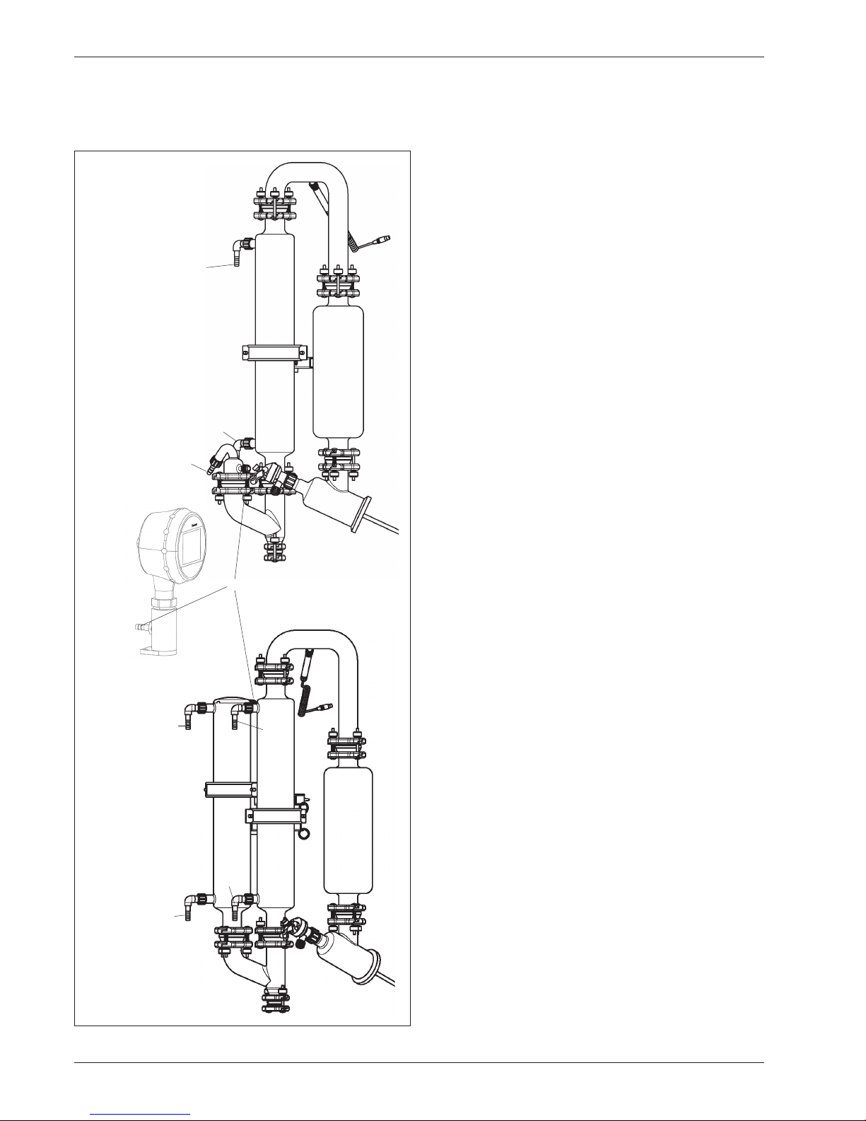
4.8 Installation of the Descending Glass Assembly
All glassware used must be intact, with no signs of cracks,
spreading impact marks, or other damage. Inspect the glassware visually before installing it.
• Fix the descending distributor head in position on the
gear head using a DN70 EasyClamp connection.
• Put the expansion vessel onto the distribution head and
fix it in position with a DN40 EasyClamp connection.
• Introduce the cooler , together with the cooler holder ,
into the pivoting clamp and connect it to the distribution head (DN40 EasyClamp connection).
• Connect to the cooler and the expansion vessel using the
U-tube and fix in position with two DN40 EasyClamp
connections.
• Align the cooler and the expansion vessel in their
vertical positions and fix them in place with a pivoting
clamp .
• Screw the cooling water hose nipples onto the cooler
.
• Insert the stop cock , with the PTFE hose mounted on
it, into the distribution head, and secure it with a standard
joint clamp SVL 30 .
• Fasten the vacuum connector to the Y-connection
with a DN40 EasyClamp connection and fix the unit in
place on the lower end of the cooler with a DN40 EasyClamp.
• Screw the temperature sensor into the support
connec tion in the U-tube .
• Check all EasyClamp connections and tighten them
evenly and in parallel.
→ The installation of the receiving fixture is described on
Page 15.
Fig. 4.7: Downgrade glass assembly
Page 16

16
Rotavapor R-220 EX
4 Putting into Operation
4.9 Installation of the Descending Glass Assembly with a 2nd Cooler
Es dürfen nur einwandfreie Glaswaren eingesetzt werden,
die keine Risse, Sterne oder sonstigen Beschädigungen
aufweisen. Die Glaswaren sind vor der Installation visuell zu
kontrollieren.
• Fix the descending distributor head in position on the
gear head using a DN70 EasyClamp connection.
• Place the expansion vessel on the distribution head and
fix it in position with a DN40 EasyClamp connection.
• Introduce the cooler , together with the cooler holder
, into the pivoting clamp .
• Connect the cooler and the expansion vessel with the
U-tube and fix them in position with two DN40 EasyClamp connections.
• Insert the second cooler , together with the cooler
hold er , into the pivoting clamp .
• Join the two coolers with the Y-connection and fix them
in position with two DN40 EasyClamp connections.
• Align the coolers ( and ) and the expansion vessel
in their vertical positions and fix them in place with
pivoting clamps ( and ).
• Screw the cooling water hose nipples onto coolers
and .
• Insert the stop cock , with the PTFE hose mounted on
it, into the distribution head, and secure it with a standard
joint clamp SVL 30 .
• Screw the temperature sensor into the support
connec tion in the U-tube.
• Check all EasyClamp connections and tighten them
evenly and in parallel.
→ The installation of the receiving fixture is described on
Page 15.
Fig. 4.8: Downgrade glass assembly with two coolers
Page 17

17
Rotavapor R-220 EX
4 Putting into Operation
4.10 Installation of the Receiving Fixture
All glassware used must be intact, with no signs of cracks,
spreading impact marks, or other damage. Inspect the glassware visually before installing it.
Single Receiver
• Fasten the support ring to the support rod with a
pivoting clamp .
• Screw the outlet valves on the receiving flask on
tight using a DN25 EasyClamp connection.
• Place the receiving flask on the support ring .
With a reflux glass assembly:
• Bring the support up and fix the flask in position on the
dis-tillate cooler using a DN25 EasyClamp connection.
With a descending glass assembly:
• Attach the branching piece to the opening at the
bottom of the Y-connection with a DN40 EasyClamp
connection.
• Insert the shut-off tap into the branching piece and
tighten it firmly.
• Bring the support up and fix the receiving flask in position on the branching piece using a DN25 EasyClamp
con nection.
Dual Receiver
• Fasten the support rings to the support rods at the
front and back using pivoting clamps .
• Screw the outlet valves firmly onto the receiving flask
using DN25 EasyClamp connections.
• Place the receiving flasks on the support rings .
• Screw the two shut-off taps into the branching pieces
( and ) and tighten them.
• Connect the branching pieces with a DN25 EasyClamp
connection. Place them on the receiving flasks , and
fasten them with DN25 EasyClamp connections.
With a reflux glass assembly:
• Bring the receiving flask up, and fasten the branching
piece to the condensate cooler using a DN25 EasyClamp connection.
With a descending glass assembly:
• Bring the receiving flask up, and fasten the branching
piece to the Y-connection using a DN25 EasyClamp
con nec tion.
Fig. 4.9: Single receiver, reflux
Fig. 4.11: Interchangeable receiver
Fig. 4.10: Single receiver, downgrade
Page 18

18
Rotavapor R-220 EX
4 Putting into Operation
4.11 Attaching and Removing Flasks
Bring up the flask
• With the snap flange coupling open, lay the flask in
posi tion.
• Close the first segment of the snap flange coupling
(The hook must latch in).
• Close the second segment of the snap flange coupling.
• Insert the closure hook and press down the closure lever.
A clear resistance must be felt when this is done. If not,
readjust the tension on the closure.
Adjusting the tension on the closure:
Open the closure hook up, and turn it.
Turning clockwise increases pressure
Turning counterclockwise reduces pressure
If the flange of the evaporating flask is outside of a certain
tolerance, the adjustment with the hook is not possible. This
evaporating flask must not be used!
Fig. 4.12: Snap flange coupling, with flask laid in place
Fig. 4.13: Closing the snap flange coupling
Fig. 4.14: Adjusting the tension on the closure
Page 19

19
Rotavapor R-220 EX
4 Putting into Operation
Fig. 4.16: 2. Opening the second segment
Fig. 4.15: Opening the closure
Removing flasks
• Place your hand under the flask to hold it from below.
• Open the closure lever .
• Use your thumb to release the closure hook .
• Flip up the first segment of the snap flange coupling.
• With your hand under the flask, lift it lightly slightly from
below and relieve pressure on it.
• Press the hook in.
• Open the second segment of the snap flange coupling.
• Lift the flask out at the top and remove it.
Page 20
20
Rotavapor R-220 EX
4 Putting into Operation
4.12 Hose Couplings
In general, observe the following items for all glass assemblies.
The cooling water inlet is always at the lower condenser
connection.
When there are two condensers (D2 und DB2), the two condensers can be connected serially, the additional condenser
being cooled first.
The following is the key for all of the hose diagrams on these
two pages.
Cooling water inlet for first condenser
Cooling water outlet for first condenser
Cooling water inlet for second condenser
Cooling water outlet for second condenser
Vacuum cover
Vacuum controller
T-piece (026117)
Fig. 4.17: Hose Couplings 1
Page 21

21
Rotavapor R-220 EX
4 Putting into Operation
The following is the key for all of the hose diagrams on these
two pages.
Cooling water inlet for first condenser
Cooling water outlet for first condenser
Cooling water inlet for second condenser
Cooling water outlet for second condenser
Vacuum cover
Vacuum controller
T-piece (026117)
Fig. 4.18: Hose Couplings 2
Page 22

22
Rotavapor R-220 EX
4 Putting into Operation
4.13 Operating the Shut-off tap
The shut-off tap is of a special design. It does not have a
con ti nuous thread on its inside for tightening it, but rather a
sli ding plane with two fixed latching positions. The closing
pres sure when it is in a closed position is provided by a
prestressed spring.
• Insert the shut-off tap on the distribution head and turn
the white lower section of the grip clockwise until the
shut-off tap is tightly seated.
• To open: Turn the gray upper section of the grip clockwise until the shut-off tap latches into the 1st position.
If the opening is not large enough, continue turning until
the shut-off tap reaches the 2nd position.
4.14 Bath replenishment (optional)
Bath replenishment inlet
Hose nipple, Ø 9 mm
Bath replenishment outlet
Hose nipple, Ø 12.5 mm
Bath discharge valve
Hose nipple, Ø 12.5 mm
Opening the needle valve slightly by one-quarter turn
pro duces a continuous supply flow.
If oil is used as heating medium, the bath replenishment has
to be emptied and disconnected from the water inlet.
Otherwise, there is a risk of water pouring into the hot oil bath.
Fig. 4.19: Shut-off tap
Fig. 4.20: Bath replenishment
Page 23

23
Rotavapor R-220 EX
4 Putting into Operation
4.15 Reset of the over-temperature protection
The rated cut-out temperature of the over-temperature
cut-out is defined by temperature class T3 and T4. The
safety temperature cutout is fitted with a microswitch with
a flameproof enclosure, which is in the “increased safety“
terminal box of the heater.
The system is based on a liquid-filled capillary tube with a
bellows fitting.
Standard EN 50019 stipulates that the safety temperature
limiter may only be reset using a tool (opening the terminal
box) and then by hand. Automatic resetting is not possible.
The temperature cutout cannot be reset until the temperature
falls below the rated cut-out temperature.
Fig. 4.21: Safety temperature cutout in the heater terminal box
Fig. 4.22: Resetting the safety temperature cutout
Page 24

24
Rotavapor R-220 EX
4 Putting into Operation
4.16 Heating Medium
Never operate the heating bath when there is no heating
medium in it!
Suitable heating media include:
• Water (some Borax should be added when using deionized water)
• Heat transfer oils suitable for use at temperatures up to
160° C (e.g., Ucon HTF 14, Fluka AG).
• Water-soluble polyethylene glycol
(e.g., Polyethylene glycol 600, Fluka AG).
After the oil bath has been standing opened for a prolonged
period, condensation water can collect on the bottom. When
the bath is used again, it must be heated above 100°C with
rotating flask in order to drive the water out.
4.17 Compressed Air Connection
The maximum permissible pressure is 8 bar. Make sure that
the compressed air is oil-free. The pressure hose must be
secured with the provided pivoting hose clamp.
Pressure is limited to 4 bar at the works. Increasing pressure
will not increase performance; rather, it causes greater air
consumption and thus results in more noise.
4.18 Vacuum Controller
The Vacuum Controller is delivered with the R-220 EX and
is already installed.
Connect the individual connections as shown here.
Vacuum connection to pump
Vacuum connection: valve – glass assembly
(see pages 18 and 19)
Vacuum connection: controller – glass assembly
(see pages 18 and 19)
Fig. 4.23: Reset the safety temperature limiter
Fig. 4.24: Valve and manometer connections
Page 25

25
Rotavapor R-220 EX
4 Putting into Operation
4.19 Splash Protector
The optionally available splash protector can be easily securely
fastened to the housing using two bolts .
The equipotential is assured using the supplied grounding
cable. In addition, the two bolts must be connected to
the cable.
4.20 Checking Installation
After installation has been completed and before doing the
first distillation, check to make sure the installation has been
carried out correctly:
• Inspect the glass visually for possible damage.
• Check that all connections (steam, water, vacuum) have
been fixed properly in position.
• Check the tightness of the vacuum (see 6.10).
Fig. 4.25: Installing the splash protector
Fig. 4.26: Checking Installation
Page 26
26
Rotavapor R-220 EX
5 Operation
5 Operation
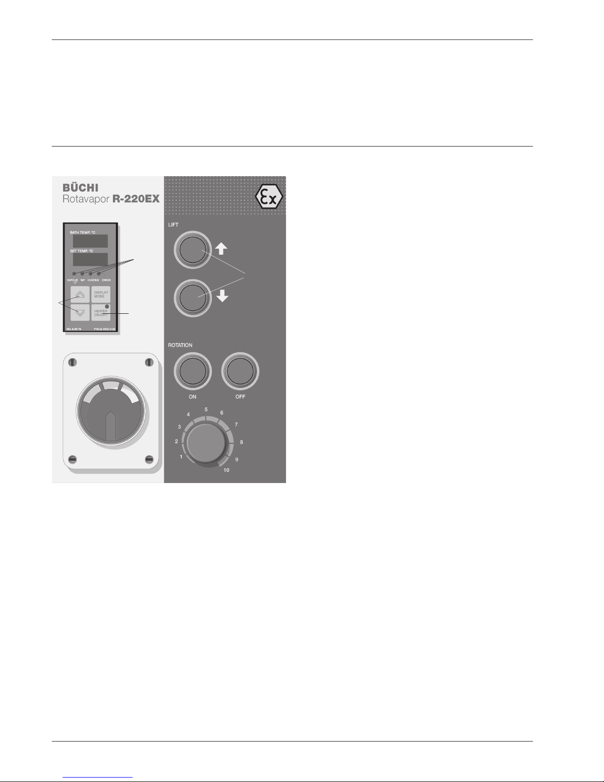
Fig. 5.1: Operating and Display Elements
Make certain that the unit has been commissioned properly
as described in Chapter 4.
5.1 Layout of the Operating and Display Elements
Main switch
Bath lift
Rotation on
Rotation off
Rotation speed setting
Heating on/off
Setpoint bath temperature input
Bath temperature display
Variable display
- Setpoint bath temperature
- Vapour temperature
- Heating
- Error
Indication lamps
- Vapour temperature
- Heat output
- Heating
- Error
The bath is lowered automatically when the unit is switched
off or in case of a power failure to ensure that the evaporating flask will in all cases remain outside the source of heat
(optional).
Rotation
The rotation is provided with a „soft start“ function. The flask
rotates at a very low speed for approx. 5 seconds and then
increases its speed to the set value. The „Rotation ON“ button
must remain depressed during this time.
The speed can be set to a value between 0 and 100 revolutions ().
Bath lift
The bath lift is provided with an upper and a lower stop and
thus cannot travel too far up or down.
Page 27

27
Rotavapor R-220 EX
5 Operation
Display
The upper display always indicates the current bath temperature. The lower display provides other information, depending
on what is selected. In the default state, the setpoint bath
temperature is displayed. The display cannot be changed
unless the heating is turned on.
Pressing „DISPLAY MODE“ once changes the display to
„Heat output“ (<%P> LED illuminates) for 10 seconds. This
figure is the clock frequency of the heating.
Pressing “DISPLAY MODE” twice displays the vapour
temperature (<VAPOUR °C> LED blinks). After 10 seconds
the display returns to the default state (setpoint bath temperature).
The LED on the „HEATER ON/OFF“ key illuminates when
the heating process is started.
If there is an error, the <ERROR> LED illuminates and a corresponding code is provided in the upper display (P184 appears if the vapour temperature sensor is not connected).
5.2 Setting the Parameters
Bath temperature
The setpoint for the bath temperature can be changed at
any time using the „UP“ and „DOWN“ arrows on the Control
Unit.
Pressing the „HEATER ON/OFF“ key activates the heater.
This is indicated with an LED in the keypad.
The heating is clocked in order to guarantee precise heat
regulation. This means that the heating is controlled in ever
smaller clock-pulse rates the closer the actual temperature
of the bath comes to the setpoint temperature. The heat
output can be displayed in percent by changing the display
to <%P>.
The <HEATING> LED also controls the heat output. It only
illuminates when the heater is triggered and thus the bath
is being heated.
Make sure that the selected temperature is within the permissible max. temperature (135°C for T4 and 150°C for T3)
Fig. 5.2: Controll Unit
Page 28

28
Rotavapor R-220 EX
5 Operation
5.3 Vacuum Controller
Operation
The vacuum controller is operated by its touch screen. To
control the vacuum in the Rotavapor® you need to set two
values. The lower vacuum level (Relay 1 set point) is the ultimate vacuum that has to be reached. When reaching the
upper vacuum level (Relay 1 reset point) the vacuum valve
opens again. In between these two levels the vacuum in the
system is being controlled.
Fig. 5.3: Vacuum Controller
ON-1
OFF-1
Pressure
Fig. 5.4: Setpoints
Page 29

29
Rotavapor R-220 EX
5 Operation
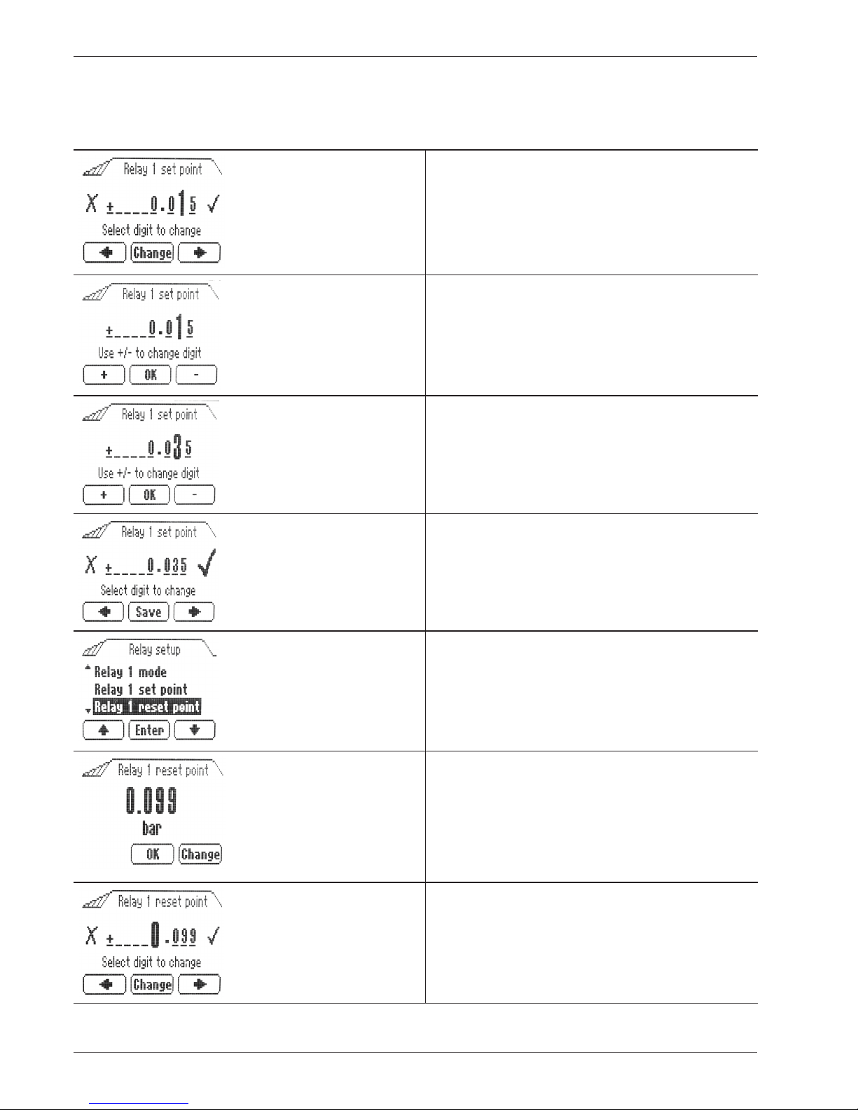
Setting options
The display shows the actual pressure in the system.
1. Touch the screen to access the menu.
2. Press “Menu” to enter the settings.
3. Select “Relay setup” by pressing the arrow buttons
and press “Enter” to open the setting menu.
4. Select “Relay 1 set point” to set the value of the pressure at which the vacuum valve will close.
5. Press “Enter” to confirm.
The actual vacuum setting is being displayed.
6. Press “Change” to set another vacuum.
7. Move to the desired digit by pressing the arrow buttons.
Page 30
30
Rotavapor R-220 EX
5 Operation
8. Press “Change” to set a new value.
9. Press “+” or “-“ to change the value.
10. Press “OK” to save the entry.
11. Select the check mark by pressing the arrow buttons.
12. Press “Save” to save the entries and exit.
13. Select “Relay 1 reset point” by pressing the arrow
buttons to set the value for the upper pressure limit at
which the vacuum valve will open again.
14. The actual vacuum setting is being displayed.
15. To change that value, press “Change”.
16. Select the desired digit by pressing the arrow buttons.
Page 31

31
Rotavapor R-220 EX
5 Operation
17. Press “Change” to change the value.
18. Press “+” or “-“ to change the value.
19. Press “OK” to save the entry.
20. Select the check mark by pressing the arrow buttons.
21. Save the vacuum setting by pressing “Save”.
22. After 10 seconds of inactivity the display reverts to
the standard screen and displays the actual pressure in
the system.
Page 32

32
Rotavapor R-220 EX
5 Operation
Fig. 5.5: Splash protector
5.4 Splash Protector
The splash protector folds back on the side lever. It is fitted
with a rear and a front stop.
5.5 Tips and Tricks
5.5.1 Selection of the Distillation Temperature
In order to attain optimum distillation conditions, the energy
supplied to the distillation from the bath must be dissipated
again across the cooler. In order to ensure this, it is best to
work according to the following rule of thumb:
Cooling water ∆T2 Boiling temperature ∆T1 Bath
max. 20 ºC 40 ºC 60 ºC
How do you attain these conditions?
• Set the bath temperature at 60 ºC.
• Adjust the cooling water. Its temperature should not be
higher than 20 ºC.
• Allow the cooling water to flow through the cooler at a
rate of about 120–150 liters/hr.
• Select the working vacuum so that the boiling point of
the solvent is at 40 ºC.
• Obtain the corresponding value for the vacuum from the
Table of solvents.
Page 33

33
Rotavapor R-220 EX
5 Operation
Advantages of a Bath Temperature of 60 °C
• Evaporating flasks can be changed without any danger
of scalding.
• The rate of water evaporation out of the heating bath is
not yet very high.
• The energy in the heating bath is being utilized very efficiently.
The solvent should condense out in approx. 2/3 to 3/4 of
the lengths of the cooling coils present.
If it is not possible to work at a bath temperature of 60ºC to
ensure gentle treatment of the product, adapt the parameters
correspondingly.
e.g.
Cooling water ∆T2 Boiling temperature ∆T1 Bath
max. 10 ºC 30 ºC 50 ºC
5.5.2 Selecting the speed
In general, it can be said that distillation performance increases as speed increases. The only exceptions to this are
products that have high viscosity and that would therefore
adhere to the flask wall, or products that foam excessively.
Reduce the speed in these cases.
5.5.3 General instructions for optimum
distillation
Distillation performance can be maximized by increasing
the temperature differences, e.g., 10ºC cooling, 40ºC vapor
temperature, and 70ºC bath temperature.
The condenser should not be used at more than 3/4 capacity
in order to avoid solvent loss (aspiration through the pump)
By using a glass assembly with two condensers (D2 or DB2),
solvent loss can be reduced even more without a resultant
decrease in distillation performance. The second condenser
can be condensed with a separate condensing circuit for
this purpose.
Make sure that the vacuum is not too low. Otherwise there
is the danger that the condensed solvent will begin to boil in
the receiving flask and thus will be aspirated (e.g., acetone
boils in a vacuum of 15 mbar at just 10ºC)
Page 34

34
Rotavapor R-220 EX
5 Operation
5.6 Table of Solvents
Solvent Formula Molar Mass Evaporation Boiling Point Spec.Gravity Vacuum in mbar for a
in g/mol Energy in J/g at 1013 mbar in g/cm3 Boiling Point at 40°C
Acetic acid C2H4O2 60.0 695 118 1.049 44
Acetone C3H6O 58.1 553 56 0.790 556
n-Amyl alcohol, n-Pentanol C5H12O 88.1 595 137 0.814 11
Benzene C6H6 78.1 548 80 0.877 236
n-Butanol, tert. Butanol C4H10O 74.1 620 118 0.810 25
(2-Methyl-2-Propanol) C4H10O 74.1 590 82 0.789 130
Carbon tetrachloride CCI4 153.8 226 77 1.594 271
Chlorobenzene C6H5CI 112.6 377 132 1.106 36
Chloroform CHCI3 119.4 264 62 1.483 474
Cyclohexane C6H12 84.0 389 81 0.779 235
Diethyl ether C4H10O 74.0 389 35 0.714 850
1,2,-Dichlorethane C2H4CI2 99.0 335 84 1.235 210
cis-1,2,-Dichlorethylene C2H2CI2 97.0 322 60 1.284 479
trans-1,2,-Dichlorethylene C2H2CI2 97.0 314 48 1.257 751
Diisopropyl ether C6H14O 102.0 318 68 0.724 375
Dioxane C4H8O2 88.1 406 101 1.034 107
DMF (Dimethylformamide) C3H7NO 73.1 153 0.949 11
Ethanol C2H6O 46.0 879 79 0.789 175
Ethyl acetate C4H8O2 88.1 394 77 0.900 240
Heptane C7H16 100.2 373 98 0.684 120
Hexane C6H14 86.2 368 69 0.660 335
Isoamyl alcohol, 3-Methyl-1-butanol C5H12O 88.1 595 129 0.809 14
Isopropyl alcohol C3H8O 60.1 699 82 0.786 137
Methanol CH4O 32.0 1227 65 0.791 337
Methylene chloride, Dichloromethane CH2CI2 84.9 373 40 1.327 850
Methylethylketon C4H8O 72.1 473 80 0.805 243
Pentachlorethane C2HCI5 202.3 201 162 1.680 13
Pentane C5H12 72.1 381 36 0.626 850
n-Propyl alcohol C3H8O 60.1 787 97 0.804 67
1,1,2,2,-Tetrachloroethane C2H2CI4 167.9 247 146 1.595 35
Tetrachloroethylene C2CI4 165.8 234 121 1.623 53
THF (Tetrahydrofurane) C4H8O 72.1 67 0.889 357
Toluol C7H8 92.2 427 111 0.867 77
1,1,1,-Trichlorethane C2H3CI3 133.4 251 74 1.339 300
Trichlorethylene C2HCI3 131.3 264 87 1.464 183
Water H2O 18.0 2261 100 1.000 72
Xylol (Mixture) C8H10 106.2 389 25
(o) 144 0.880
(m) 139 0.864
(p) 138 0.861
Table 5.1: Table of Solvents (CRC Handbook, 65th Ed)
Page 35

35
Rotavapor R-220 EX
6 Maintenance
6 Maintenance
Please note all rules aimed at keeping the rotary evaporator
in a functional condition. These also include periodic cleaning
and inspection for any damage that might have occurred.
Make certain that the supply of water, compressed air, and
power to the unit has been interrupted before doing any
maintenance work on the unit. Always support the bath
from below, on the underside of the bath whenever doing
any repair work.
6.1 Troubleshooting
Fig. 6.1: Snap flange coupling, closed
Fault Possible cause Remedy
Bath cannot be lifted Pressure too low Increase pressure (min. 4 bar, max. 8 bar)
Leaks in connections Contact service department
Bath lift defective Contact service department
Power supply off Connect
Heating does not operate Safety temperature cutout has Reset safety temperature cutout
been activated (see Chapter 4.15)
Level sensor is activated Fill bath with heating medium
PT-1000 defective (no display) Contact service department
Heater coils defective Contact service department
Rotation does not function Pressure too low Increase pressure (min. 4 bar, max. 8 bar)
Rotary drive defective Contact service department
Power supply off Connect
Operator’s panel only Connection to intrinsically safe Contact service department
displays dashes operator’s panel interrupted
Table 6.1: Troubleshooting
6.2 Taking Apart the Snap Flange Coupling
• Close the two segments of the snap flange coupling.
• Turn the snap flange coupling by 180°, until the closure
faces down.
• Have Tool No. 20075 ready at hand.
• Reopen the closure.
• Lift the 1st segment of the snap flange coupling to open it.
• Lift the 2nd segment of the snap flange coupling to open it.
• With three fingers at the tip, reach under the middle segment and raise it up.
• Insert Tool No. 20075 in at the side, between the lugs
on the positional lock. Turn lightly until the pin becomes
un latched. Take the snap flange coupling assembly off.
• Clean the snap flange coupling.
Page 36

36
Rotavapor R-220 EX
6 Maintenance
6.3 Assembling the Snap Flange Coupling
• Insert the snap flange coupling from above, until the pins
in the lock latch into the hole on the lug.
• Close the two segments of the snap flange coupling.
• Turn the snap flange coupling again by 180°, until the
closure lies at the top.
• Lift the two segments of the snap flange coupling to open
them.
• Lay the neck of the glass flask into the middle segment
and raise the flask slightly.
• Pull the segment on the left back slightly and close it until
the hook latches in place.
• Close the segment on the right.
• Insert the closure hook and close the snap flange coupling
with the closure lever. A clear resistance must be felt when
doing this. Otherwise no seal can be fully guaranteed.
6.4 Removing the Evaporating Flask Seal
• Seal the holder for the seal by 180°, until the opening
faces up.
• Take hold of the seal with both hands, from above and
from the front, and pull it out slowly.
• Tilt the seal slightly and carefully pull it all the way out. Be
care ful not to damage the glass centering bulge when
doing so.
• Remove the vapor duct.
Fig. 6.3: Removing the evaporating flask seal
Fig. 6.2: Assembling the snap flange coupling
Page 37

37
Rotavapor R-220 EX
6 Maintenance
6.5 Inserting the evaporating flask seal
• Insert the vapor duct.
• Insert the seal. Using gentle pressure, shove it across the
lock preventing it from twisting out of position, and then
shove it all the way in. Press it with both thumbs until it
latches in position.
• The knob in the gearhead must come to rest in the
notch in the vapour duct.
6.6 Replacement of the Seals for the Distribu tion
Head
• Open the DN70 EasyClamp by releasing the knurled nuts
on all 3 bolts, but do not screw the nuts completely off.
• Tilt the top bolt out toward the back.
• Open the upper and lower EasyClamp segments and
carefully lift the distribution head off the glass assembly.
Fig. 6.4: Inserting the evaporating flask seal 1
Fig. 6.6: Replacement of the seals for the distribution head
Fig. 6.5: Inserting the evaporating flask seal 2
Page 38

38
Rotavapor R-220 EX
6 Maintenance
• Take out the seal laid in at the front and replace it.
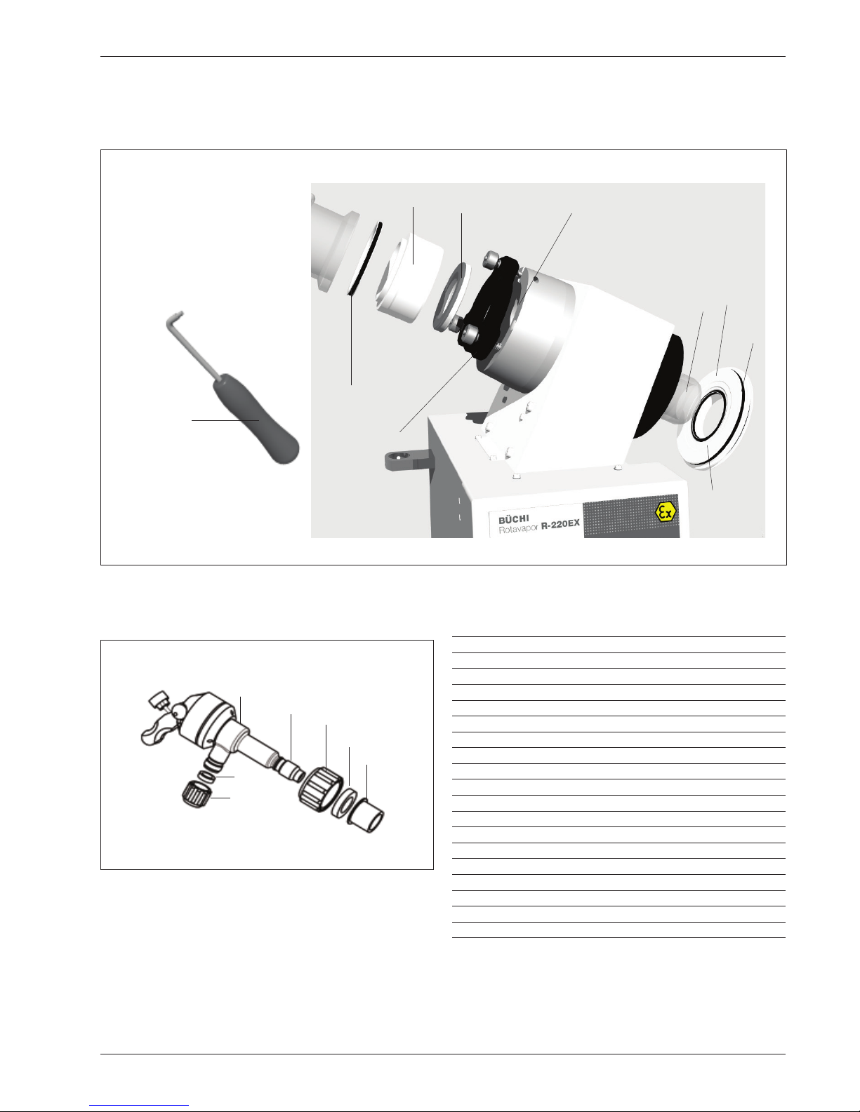
6.7 Replacement of the Vacuum Seal
• Remove the DN70 EasyClamp completely and take off
the distribution head.
• Pull the cylindrical seal holder out and turn it over.
• Insert Tool No. 20075 into the metal guide on the seal
and pull the seal out.
• Put in the new seal with the dark scraper ring facing the
inside and the metal guide ring facing outward.
• Insert the cylinder with the seal at the back lying on the
in-side.
• Insert the seal at the front.
• Provisionally install the EasyClamp using 2 bolts.
• Set the distribution head of the glass assembly on top of
the seal.
• Close the segments of the EasyClamp. Flip the top bolt
up and in, and hand-tighten all 3 knurled nuts.
Tip:
When the glass assembly "R" is in place, the vacuum seal
can be taken out and/or cleaned without the glass assembly
having to be removed.
• Remove the complete DN70 EasyClamp assembly from
the distribution head.
• Using a socket wrench, release the fastening for the support rod.
• Carefully turn the glass assembly out around the support
rod as an axis.
• Remove the seal.
6.8 Cleaning
Use commercially available cleaning agents to clean the
glass ware.
Merely wipe the housing off with a damp cloth (without using
any organic solvents).
Use a commercially available de-liming agent to dissolve
resi dues of lime in the bath and flush the bath out well.
Fig. 6.7: Replacement of the Vacuum Seal 1
Fig. 6.8: Replacement of the Vacuum Seal 2
Page 39

39
Rotavapor R-220 EX
6 Maintenance
6.9 Vacuum Seal
The seal should be cleaned whenever necessary, but at least
once every six months.
During the intake phase, which lasts approx. 10 hours, the
seal will show signs of greater material loss due to wear. This
is normal for a PTFE seal.
Cleaning
Before the packet of seals can be removed, the distribution
head must be released and screwed off. The complete seal
packet can then be taken out and cleaned.
Wipe off the sealing lip using a soft, dry cloth. Clean the
running surface on the vapor duct well.
Regular cleaning of the seal will result in a longer service
life for it.
6.10 Testing for Leaks
After the rotary evaporator has been completely assembled
and before putting it into operation, i.e., while it is clean and
dry, check for tightness of the vacuum. To do this, evacuate
the unit to below 100 mbar and then close the vacuum line.
The rate of pressure rise must not exceed 3 to 5 mbar per
15 minutes.
A greater pressure rise indicates a leak in the vacuum seal.
In such a case, recheck all EasyClamp connections and all
valves.
6.11 Customer Service
No intervention on or in the unit is permissible except when
done by authorized Service personnel. These are individuals with a well-backed technical professional training and
knowl edge of the dangers that result from a failure to observe
the safety precautions required. BUCHI’s Customer Service
rep resentatives have available to them a Service Manual
specific to the unit in question. That manual is issued only
to authorized Service personnel.
The addresses of BUCHI’s official Customer Service rep resen tatives are shown on the back cover of this Operation
Manual. Please turn to these representatives should you
have any malfunctions, technical questions, or problems in
using the unit.
BUCHI’s Customer Service Dept. will be ready and happy to
offer the following services:
• Spare parts service
• Repair service
• Maintenance service
• Technical consultation.
Page 40

40
Rotavapor R-220 EX
7 Taking out of Operation
7 Taking out of Operation
Remove all hazardous materials and clean the unit thoroughly.
This prevents any risk that individuals could suffer injuries due
to contact with hazardous materials.
In addition, in the case of service or repair, details on the
most recently processed substance must be provided. This
means that a Material Safety Data Sheet for the product processed must also be provided. This is absolutely necessary
to protect our service personnel.
7.1 Storage
Always store the unit and spare parts for it in a clean and
dry location.
7.2 Packing / Transport
The original packing has been specially designed for transporting the unit and the glass parts for it. Use only the original
packing materials for any further transport.
7.3 Waste Disposal
Table 9.2 in the Appendix, Chapter 9, contains a list of the
mate rials, including their material codes, used for the most
important components of the unit. This list has been provided in order to enable environmentally correct disposal
of the rotary evapo rator. It ensures that the parts can be
separated and sent for appropriate recycling. Please refer to
the pertinent guidelines when disposing of electrical parts. In
addition, observe all regional and local laws covering waste
disposal.
Used batteries may be returned directly to your BUCHI representative for disposal.
Page 41

41
Rotavapor R-220 EX
8 Spare Parts and Accessories
8 Spare Parts and Accessories
Only original BUCHI accessories and spare parts ensure safe
operation and a proper functioning of the unit. The use of
spare parts and accessories other than those from BUCHI is
permissible only with prior approval of the manufacturer. The
Spare Parts Catalog may be used for purposes of assembly
and disassembly only in conjunction with the corresponding
Chapters 4 and 7 in this Operation Manual. Dis-closure and
distribution to third parties, and manufacturing based on this
manual are strictly forbidden.
Copyright by BÜCHI Labortechnik AG. All rights reserved.
Page 42

42
Rotavapor R-220 EX
8 Spare Parts and Accessories
Fig. 8.1: Spare parts, Glass Assemblies D, D2, DB, DB2
D D2
DB
27277
41307
41442
41131
46512
41076
46513
41436
3577/5155
41443
41348
41155
41333
27289
41130
41076
27277
46512
41307
41333
41131
41442
41130
46513
27289
41155
41399
41348
41076
46515
41120
46516
11055587
41442
41307
27277
41348
41443
41436
3577/5155
DB2
41076
46515
41307
41442
41155
41399
11055587
27277
41348
46516
41436
3577/5155
Page 43

43
Rotavapor R-220 EX
8 Spare Parts and Accessories
8.1 Spare Parts: Glass Assemblies D, D2, DB, DB2
Component Ordering No.
Threaded sleeve Svl 22 03577
Seal Svl 22 Id 17 PTFE 05155
PTFE hose, Outer Diam. 10.0x1.0 27277
Screwed fitting Svl 22 27289
Hose nipple 41436
Temperature sensor B, complete 41076
Glass holder B, complete 41120
EasyClamp, DN25 41130
EasyClamp, DN40 41131
Pivoting clamp, complete 41151
Glass holder, complete 41155
Clamping lever 41156
2 bolts, complete, for EasyClamp DN25 41240
3 bolts, complete, for EasyClamp DN40 41241
Distribution piece “D” 41307
Cooler, 3-coil 41333
Inlet valve, complete 41348
Condenser R 41399
Expansion vessel 41442
Vacuum connector 41443
Condenser, Bullfrog R 41458
U-tube 46512
Y-connection 46513
Y-connection Bullfrog 11055587
U-tube Bullfrog 46515
Condenser Bullfrog D 46516
Table 4: Spare parts, Glass Assemblies D, D2, DB, DB2
41151
41155
41120 (Bullfrog)41156
41241 (DN40)
41240 (DN25)
Page 44

44
Rotavapor R-220 EX
8 Spare Parts and Accessories
3577
5155
41436
25979 /
25981
25124
46518
41079
41060
41076
27277/
41164
41348
46511
46510
27289
41348
46511
46510
27289
27277 /
41164
41076
41060
41155
41399
Fig. 8.2: Spare parts, Glass Assemblies R, RB, C
R RB
C
41348
46511
46510
3577
5155
41436
41458
41120
27289
27277 /
41164
41130
41130
41130
41131
41131
41131
41348
46511
41076
41060
41076
41060
41228
Page 45

45
Rotavapor R-220 EX
8 Spare Parts and Accessories
8.2 Spare Parts: Glass Assemblies R, RB, C
Component Ordering No.
Threaded sleeve Svl 22 03577
Seal Svl 22 Id 17 PTFE 05155
Cold trap 25124
Cold trap cover 25979
Seal for cold trap 25981
PTFE hose, Outer Diam. 10.0x1.0 27277
Screwed fitting Svl 22 27289
Hose nipple 41436
Shut-off tap, large, complete 41060
Temperature sensor B, complete 41076
Glass holder C, complete 41079
Glass holder B, complete 41120
EasyClamp DN25 41130
EasyClamp DN40 41131
Pivoting clamp, complete 41151
Glass holder, complete 41155
Clamping lever 41156
Set of 10 teflon discs 41228
Set of bolts for EasyClamp, DN25 41240
Set of bolts for EasyClamp, DN40 41241
Inlet valve, complete 41348
Condenser R 41399
Condenser, Bullfrog R 41458
Condensate cooler 46510
Distribution piece "R" 46511
Cold trap 46518
Table 5: Spare parts, Glass Assemblies R, RB, C
41241 (DN40)
41151
41155
41120 (Bullfrog)
41079 (Cold trap)
41156
41240 (DN25)
Page 46

46
Rotavapor R-220 EX
8 Spare Parts and Accessories
Fig. 8.3: Interchangeable receiver (W)
Fig. 8.4: Single receiver (E)
41062
46520
46519
41061
41447
41252
41151
46521
41062
41130
46519
41151
41252
41061
46574
46574
8.3 Miscellaneous
Component Ordering No.
Interchangeable receiver (W)
Ventilation cap 46574
Outlet valve, DN25/2 41061
Shut-off tap, small, complete 41062
EasyClamp, DN25 41130
Pivoting clamp, complete 41151
Base for flask 41252
Branching piece 1 41447
Receiving flask 10L 46519
Branching piece 2 46520
Single receiver (E)
Ventilation cap 46574
Outlet valve, DN25/2 41061
Shut-off tap, small, complete 41062
EasyClamp, DN25 41130
Pivoting clamp, complete 41151
Base for flask 41252
Receiving flask 10L 46519
Branching piece 46521
Hose Connections
Pressure tube ID 8,0 (PVC) 04113
Vacuum-hose Id 6 x 5.0 (rubber) 11062966
Condenser hose, ID 10,0 x 2,0 (PVC) 27146
PTFE hose, ID 8,0 x 1,0 27277
PTFE hose, ID 8,0 x 1,0 conductive 40039
Spiralflex hose, ID 16 mm 41441
Page 47
47
Rotavapor R-220 EX
8 Spare Parts and Accessories
Component Ordering No.
Sealing elements
Seal SVL 30 00398
Screw Cap SVL 30 03223
Screw Cap SVL 15 03549
Seal tool 20075
O-ring 130x5.0 Fpm70 27378
Vapor duct 41084
Seal holder 41094
Vacuum seal 41095
Evaporating flask seal, complete 41121
Easy Clamp element, DN70 41135
Support ring inlet valve 41147
Set of 5 O-rings 64x5.0 41229
Set of 10 cover caps, D11 Pa 41230
Set of distribution head sealings 41231
Glass body 41346
Inlet valve, complete 41348
Connection, PTFE 41354
PTFE bellow 41388
Set of 5 SVL 15 seals 41946
Fig. 8.5: Sealing elements
20075
41135
41230
41231
27378
41121
41084
41229
41094
41095
Fig. 8.6: Inlet valve, complete
41346
41354
03223
00398
41946
03549
41147
Page 48

48
Rotavapor R-220 EX
8 Spare Parts and Accessories
Fig. 8.9: Drying flask
Fig. 8.7: Snap flange coupling, complete
Fig. 8.8: Evaporating flask
41112
41110
41111
Component Ordering No.
Clip 41110
Detent 41111
Snap flange coupling, completel. 41112
6 L Evaporating flask 27470
10 L Evaporating flask 27469
20 L Evaporating flask 27468
This special flask is particularly suited for drying powdery
sub stances or a homogeneous mixture of solid products. The
baffles attached on the circumference of the flask ensure an
intensive circulation of the contents inside the flask.
10 L Drying flask 28592
20 L Drying flask 28593
Cover for evaporating flask, PE 11057349
Page 49

49
Rotavapor R-220 EX
8 Spare Parts and Accessories
Fig. 8.11: Splash Protector
Fig. 8.12: Trolley
Fig.8.13: Manual flask handler
8.4 Accessories
Component Ordering No.
Splash Protector
Splash Protector 46431
Trolley
Trolley for R-220 and R-220Ex 41257
Manual flask handler
Manual flask handler for 20L flask 41400
Page 50

50
Rotavapor R-220 EX
8 Spare Parts and Accessories
Fig. 8.14: Valve body complete and Controller Ex
Vacuum Controller (EX)
Component Ordering No.
Vacuum controller Ex, complete 11060831
Valve body, stainless, complete 41424
In-line valve 24 V (encapsulated) 41488
Page 51

51
Rotavapor R-220 EX
9 Appendix
9 Appendix
9.1 Technical Data
R-220 EX
Power Connection 4.2 kW
Connection Voltage 200 VAC / 230 VAC / 400 VAC ± 10 %
Frequency 50 - 60 Hz
Site condition for indoor use only, altitude up to 2000 m.
maximum relativ humidity 80% for temperatures up to 30°C
decreasing linearly to 50% relative humidity at 40°C
Ambient temperature 5-40°C
Aeration Oil-free, 4 to 8 bar, 10m3/hour
Evaporator output Up to 4 l/h water, higher for other solvents
(depending on the heat of evaporation)
Rotary drive Pneumatic
Speed control Infinitely variable using precision control valve
Bath output 3600 W, Heat introduction 3W/cm
2
Bath dimensions Ø 430 mm x 240 mm,
Bath capacity 20 l, without flask immersed
Bath pan Stainless steel X2CrNiMo 17 13 2 (1.4404 or 316L)
Bath heater control Electronic, with PT-1000, Control accuracy -2 to +1°C
Range of bath temperatures 20°C – 150°C
Overheating protection Mechnical overtemperature switch (135°C or 175°C)
Bath lift Pneumatic
Measurement of vapor temperature PT-1000
Displays Vapor temperature and bath temperature
Vacuum pump Recommended suction output 2 – 4 m3/h
Cooling water consumption 120 – 200 l/h, with needle valve control
Cooling water pressure max. 2.7 bar abs., without any pulsation
Weight 75 kg, without glass
Dimensions max. 1800 mm high (1430 mm for Bullfrog version),
max. 1250 mm wide, max. 650 mm deep
(these dimensions vary depending on glass assembly)
Table 9.1: Technical Data
9.2 Materials Used
Part Description Code
Chassis X5CrNi 18 10 1,4301 or 304
Bath pan X2CrNiMo 17 13 2 1,4404 or 316L
Glass Borosilicate 3.3
Seals Polytetrafluorethylene PTFE
Taps Polytetrafluorethylene PTFE
Table 9.2: Materials Used
Page 52

52
Rotavapor R-220 EX
9 Appendix
9.3 Error Messages
Error messages indicate a defect on the unit and are signalled
on the upper display. They appear with an “P” at the start,
followed by a specific number:
P184 : Message: Output from the vapour temperature sensor not within the valid range.
Cause: Sensor defective or not connected.
Action: The bath heater is switched OFF.
Acknowledgment: Switch the unit OFF.
Table 9.3: Error messages
9.4 FCC requirements (for USA and Canada)
English:
This equipment has been tested and found to comply with the limits for a Class A digital device, pusuant
to both Part 15 of the FCC Rules and the radio interference regulations of the Canadian Department of
Communi cations. These limits are designed to provide reasonable protection against harmful interference
when the equipment is operated in a commercial environment.
This equipment generates, uses and can radiate radio frequency energy and, if not installed and used in
accor dance with the instruction manual, may cause harmful interference to radio communications. Operation of this equipment in a residential area is like to cause harmful interference in which case the user will be
required to correct the interference at his own expense.
Français:
Cet appareil a été testé et s'est avéré conforme aux limites prévues pour les appareils numériques de
classe A et à la partie 15 des règlementation FCC à la règlementation des radio-interférences du Canadian
Department of communications. Ces limites sont destinées à fournir une protection odéquate contre les
inter fé rences nétastes lorsque l'appareil est utilisé dans un environnement commercial.
Cet appareil génère, utilise et peut radier une énergie à fréquence radio électrique, il est en outre susceprible
d'engendrer des interferences avec les communications radio, s'il n'est pas installé et utilisé conformément
aux instructions du mode d'emploi. L'utilisation de cet appareil dans les zones résidentielles peut causer
des interférences nèfastes, auquel cas l'exploitant sera amené à prendre les dispositions utiles pour polier
aux interférences à ses propres frais.
Page 53

EU-Konformitätserklärung
Déclaration UE de conformité
EU-Declaration of conformity
Wir / Nous / We, thuba AG
Postfach 431
CH-4015 Basel
Switzerland
erklären in alleiniger Verantwortung, dass die
déclarons de notre seule responsabilité que les
bearing sole responsibility, hereby declare that the
Rotavapor R-220 Ex / R-250 Ex
den grundlegenden Sicherheits- und Gesundheitsschutzanforderungen nach Anhang II der untenstehenden
Richtlinie entspricht.
répond aux exigences essentielles en ce qui concerne la sécurité et la santé fondamentales selon l’annexe II des
directives suivantes.
satisfies the fundamental health and safety protection requirements according to Annex II of the directive named below.
Bestimmungen der Richtlinie
Désignation de la directive
Provisions of the directive
Titel und/oder Nummer sowie Ausgabedatum der Normen
Titre et/ou No. ainsi que date d’émission des normes
Title and/or No. and date of issue of the standards
2014/34/EU: Geräte und Schutzsysteme zur
bestimmungsgemässen Verwendung in
explosionsgefährdeten Bereichen
2014/34/UE: Appareils et systèmes de protection
destinés à être utilisés en atmosphère explosible
2014/34/EU: Equipment and protective systems
intended for use in potentially explosive atmospheres
EN 60079-0:2012+A11:2013
EN 60079-1:2014
EN 60079-7:2015
EN 60079-11:2012
EN 61439-1:2011
EN 61439-2:2011
EN 60204-1:2006+A1:2010
EN 60730-1:2012
EN 60730-2-9:2011
EN 60519-1:2013
EN 60519-2:2007
EN 60529:1991+A1:2000+A2:2013
EN 13463-1 :2009
EN 13463-5 :2011
2014/30/EU: Elektromagnetische Verträglichkeit
2014/30/UE: Compatibilité électromagnétique
2014/30/EU: Electromagnetic compatibility
EN 60947-1:2007+A1:2011+A2:2014
EN 61000-6-2:2005
EN 61000-6-4.2007+A1:2011
Folgende benannte Stelle hat die Bewertung des Moduls
«Qualitätssicherung Produktion» nach der Richtlinie
2014/34/EU Anhang IV durchgeführt:
L’organe reconnu ci-après a procédé à l’évaluation de la conformité
prescrite par la directive 2014/34/UE de l’annexe IV:
The following notified body has carried out the conformity
assessment procedure according to Directive 2014/34/EU,
Annex IV:
DEKRA EXAM GmbH
0158
Dinnendahlstrasse 9
DE44809 Bochum
Basel, 3. Juli 2016
Peter Thurnherr
Ort und Datum
Lieu et date
Place and date
Geschäftsführender Inhaber, Elektroingenieur FH
Administrateur délégué, ingénieur HES
Managing Proprietor, B. Sc. Electrical Engineer
Page 54

Quality in your hands
BUCHI Affiliates:
We are represented by more than 100 distribution partners worldwide.
Find your local representative at: www.buchi.com
BUCHI Support Centers:
Europe
Switzerland/Austria
BÜCHI Labortechnik AG
CH – 9230 Flawil
T +41 71 394 63 63
F +41 71 394 64 64
buchi@buchi.com
www.buchi.com
Benelux
BÜCHI Labortechnik GmbH
Branch Offi ce Benelux
NL – 3342 GT Hendrik-Ido-Ambacht
T +31 78 684 94 29
F +31 78 684 94 30
benelux@buchi.com
www.buchi.com/bx-en
France
BUCHI Sarl
FR – 94656 Rungis Cedex
T +33 1 56 70 62 50
F +33 1 46 86 00 31
france@buchi.com
www.buchi.com/fr-fr
Germany
BÜCHI Labortechnik GmbH
DE – 45127 Essen
T +800 414 0 414 0 (Toll Free)
T +49 201 747 49 0
F +49 201 747 49 20
deutschland@buchi.com
www.buchi.com/de-de
Italy
BUCHI Italia s.r.l.
IT – 20010 Cornaredo (MI)
T +39 02 824 50 11
F +39 02 575 12 855
italia@buchi.com
www.buchi.com/it-it
Russia
BUCHI Russia/CIS
Russia 127287 Moscow
T +7 495 36 36 495
russia@buchi.com
www.buchi.com/ru-ru
United Kingdom
BUCHI UK Ltd.
GB – Oldham OL9 9QL
T +44 161 633 1000
F +44 161 633 1007
uk@buchi.com
www.buchi.com/gb-en
Germany
BÜCHI NIR-Online
DE – 69190 Walldor f
T +49 6227 73 26 60
F +49 6227 73 26 70
nir-online@buchi.com
www.nir-online.de
China
BUCHI China
CN – 200233 Shanghai
T +86 21 6280 3366
F +86 21 5230 8821
china@buchi.com
www.buchi.com/cn-zh
India
BUCHI India Private Ltd.
IN – Mumbai 400 055
T +91 22 667 75400
F +91 22 667 18986
india@buchi.com
www.buchi.com/in-en
Indonesia
PT. BUCHI Indonesia
ID – Tangerang 15321
T +62 21 537 62 16
F +62 21 537 62 17
indonesia@buchi.com
www.buchi.com/id-in
Japan
Nihon BUCHI K.K.
JP – Tokyo 110-0008
T +81 3 3821 4777
F +81 3 3821 4555
nihon@buchi.com
www.buchi.com/jp-ja
Korea
BUCHI Korea Inc.
KR – Seoul 153-782
T +82 2 6718 7500
F +82 2 6718 7599
korea@buchi.com
www.buchi.com/kr-ko
Malaysia
BUCHI Malaysia Sdn. Bhd.
MY – 47301 Petaling Jaya,
Selangor
T +60 3 7832 0310
F +60 3 7832 0309
malaysia@buchi.com
www.buchi.com/my-en
Singapore
BUCHI Singapore Pte. Ltd.
SG – Singapore 609919
T +65 6565 1175
F +65 6566 7047
singapore@buchi.com
www.buchi.com/sg-en
Thailand
BUCHI (Thailand) Ltd.
TH – Bangkok 10600
T +66 2 862 08 51
F +66 2 862 08 54
thailand@buchi.com
www.buchi.com/th-th
Asia
America
Brazil
BUCHI Brasil Ltda.
BR – Valinhos SP 13271-200
T +55 19 3849 1201
F +55 19 3849 2907
brasil@buchi.com
www.buchi.com/br-pt
USA/Canada
BUCHI Corporation
US – New Castle, DE 19720
T +1 877 692 8244 (Toll Free)
T +1 302 652 3000
F +1 302 652 8777
us-sales@buchi.com
www.buchi.com/us-en
South East Asia
BUCHI (Thailand) Ltd.
TH-Bangkok 10600
T +66 2 862 08 51
F +66 2 862 08 54
bacc@buchi.com
www.buchi.com/th-th
Middle East
BÜCHI Labortechnik AG
UAE – Dubai
T +971 4 313 2860
F +971 4 313 2861
middleeast@buchi.com
www.buchi.com
Latin America
BUCHI Latinoamérica Ltda.
BR – Valinhos SP 13271-200
T +55 19 3849 1201
F +55 19 3849 2907
latinoamerica@buchi.com
www.buchi.com/es-es
 Loading...