

Page 1

Software Developer's Manual
ESC/P Command Reference
PT-P900W/P950NW
Version 1.02
Page 2

The Brother logo is a registered trademark of Brother Industries, Ltd.
Brother is a registered trademark of Brother Industries, Ltd.
© 2016 Brother Industries, Ltd. All rights reserved.
BarStar Pro Encode Library (DataMatrix, MaxiCode, PDF417, RSS, CODE93, POSTNET, AztecCode)
Copyright (c) 2007 AINIX Corporation. All rights reserved.
QR Code is a registered trademark of DENSO WAVE INCORPORATED in Japan and other countries.
QR Code Generating Program Copyright © 2008 DENSO WAVE INCORPORATED
Each owner whose software title is mentioned in this document has a Software License Agreement specific to
its proprietary programs.
Any trade names and product names of companies appearing on Brother products, related documents and
any other materials are all trademarks or registered trademarks of those respective companies.
Page 3

IMPORTANT - PLEASE READ CAREFULLY
Note
This documentation (“Documentation”) provides information that will assist you in controlling your Printer
PT-P9XX (where “P9XX” is the model name).
You may use the Documentation only if you first agree to the following conditions.
If you do not agree to the following conditions, you may not use the Documentation.
Condition of Use
You may use and reproduce the Documentation to the extent necessary for your own use of your Printer
Model (“Purpose”). Unless expressly permitted in the Documentation, you may not;
(i) copy or reproduce the Documentation for any purpose other than the Purpose,
(ii) modify, translate or adapt the Documentation, and/or redistribute it to any third party,
(iii) rent or lease the Documentation to any third party, or,
(iv) remove or alter any copyright notices or proprietary rights legends included within the Documentation.
No Warranty
a. Any updates, upgrades or alteration of the Documentation or Printer Model will be performed at the sole
discretion of Brother. Brother may not respond to any request or inquiry about the Documentation.
b. THIS DOCUMENTATION IS PROVIDED TO YOU "AS IS" WITHOUT WARRANTY OF ANY KIND,
WHETHER EXPRESS OR IMPLIED, INCLUDING, BUT NOT LIMITED TO, THE IMPLIED WARRANTY
OF FITNESS FOR A PARTICULAR PURPOSE. BROTHER DOES NOT REPRESENT OR WARRANT
THAT THIS DOCUMENTATION IS FREE FROM ERRORS OR DEFECTS.
c. IN NO EVENT SHALL BROTHER BE LIABLE FOR ANY DIRECT, INDIRECT, PUNITIVE, INCIDENTAL,
SPECIAL OR CONSEQUENTIAL DAMAGES OR ANY DAMAGES WHATSOEVER, ARISING OUT OF
THE USE, INABILITY TO USE, OR THE RESULTS OF USE OF THE DOCUMENTATION OR ANY
SOFTW ARE PROGRAM OR APPLICATION YOU DEVELOPED IN ACCORDANCE WITH THE
DOCUMENTATION.
Page 4

ESC/P Command Reference
Contents
Introduction ····························································································1
What is ESC/P? ·······················································································2
1. Using ESC/P Commands ······································································3
2. Examples of Using ESC/P Commands ···················································5
3. ESC/P Command Limitations ······························································ 10
3.1 Print area........................................................................................................................ 10
3.2 Characters ..................................................................................................................... 11
3.2.1 Character sizes ............................................................................................. 11
3.3 Print position................................................................................................................. 12
3.3.1 Characters ..................................................................................................... 12
3.3.2 Bitmaps, barcodes and do wnloaded images............................................... 12
3.4 Line feed amount .......................................................................................................... 13
4. Control Code List··············································································· 14
5. Control Command Details··································································· 17
5.1 Character/style selection commands........................................................................ 17
ESC R Select international character set ..................................................... 17
ESC k Select font .......................................................................................... 18
ESC t Select character code table .............................................................. 19
5.2 Text printing commands.............................................................................................. 20
ESC 4 Apply italic style ................................................................................. 20
ESC 5 Cancel italic style ............................................................................... 20
ESC E Apply bo ld style ................................................................................. 21
ESC F Cancel bold style ............................................................................... 21
ESC G Apply double-strike printing............................................................... 22
ESC H Cancel double-strike printing ............................................................ 22
ESC W Specify double-width characters ....................................................... 23
SI Specify compressed characters........................................................ 24
ESC SI Specify compressed characters........................................................ 24
DC2 Cancel compressed characters ........................................................ 24
ESC – Apply/cancel underlining ................................................................... 25
ESC ! Global formatting ............................................................................... 26
ESC X Specify character size ....................................................................... 27
ESC if Apply/cancel a frame ......................................................................... 28
CAN Clear text ............................................................................................ 28
DEL Delete one character ......................................................................... 29
ESC CR Not available .................................................................................... 29
5.3 Line feed commands.................................................................................................... 30
ESC 0 Specify line feed of 1/8 inch .............................................................. 30
ESC 2 Specify line feed of 1/6 inch .............................................................. 30
ESC 3 Specify line feed of n/180 inch .......................................................... 31
ESC A Specify line feed of n/60 inch ............................................................ 31
5.4 Horizontal movement commands .............................................................................. 32
CR Carriage return................................................................................... 32
ESC $ Specify absolute horizontal position ................................................. 33
ESC \ Spec if y relative horizontal position ................................................... 33
ESC a Specify alignment .............................................................................. 34
5.5 Vertical movement commands ................................................................................... 35
LF Line feed ............................................................................................ 35
FF Page feed........................................................................................... 35
ESC J Forward paper feed ........................................................................... 36
- i -
Page 5

ESC/P Command Reference
5.6 Paper formatting commands ...................................................................................... 37
ESC il Specify label length ........................................................................... 37
ESC im Specify margin width ......................................................................... 37
5.7 Printer control commands .......................................................................................... 38
ESC @ Initialize .............................................................................................. 38
5.8 Graphics commands .................................................................................................... 40
ESC * Select bit image ................................................................................. 40
ESC K 8-dot single-density bit image ........................................................... 46
ESC L 8-dot double-density bit image.......................................................... 48
ESC Y 8-dot double-speed double-density bit image .................................. 49
ESC Z 8-dot quadruple-density bit image .................................................... 49
5.9 Advanced commands .................................................................................................. 51
ESC i B Barcode .............................................................................................. 51
ESC i Q 2D barcode (QR Code) ..................................................................... 55
ESC i P Specify QR Code version .................................................................. 59
ESC i V 2D barcode (PDF417) ....................................................................... 60
ESC i D 2D barcode (DataMatrix) ................................................................... 63
ESC i M 2D barcode (MaxiCode) .................................................................... 66
ESC i J 2D barcode (AztecCode) .................................................................. 68
ESC i F Print transferred data......................................................................... 70
ESC i a Switch command mode ..................................................................... 74
ESC i S Request printer status ....................................................................... 75
ESC i L Apply/cancel rotated printing ............................................................ 81
ESC i C Specify cut setting ............................................................................. 82
ESC i UB Specify baud rate ............................................................................... 83
ESC i Ub Specify bit length ............................................................................... 84
ESC i UP Specify parity setting ......................................................................... 84
ESC i UC Specify busy control .......................................................................... 85
5.10 Advanced static commands ..................................................................................... 86
ESC iXE2 Specify barcode margin setting ........................................................ 86
ESC iXE1 Retrieve barcode margin setting....................................................... 86
Appendix A: Specifications ···································································· 87
Appendix B: Character Code Tables ······················································· 88
Character code tables ........................................................................................................ 88
International character set table....................................................................................... 91
Appendix C: Introducing the Brother Developer Center ··························· 92
- ii -
Page 6

ESC/P Command Reference
Introduction
This material provides the necessary information for directly controlling PT-P9XX.
This information is provided assuming that the user has full understanding of the operating system being used
and basic mastery of communication interfaces in a developer's environment.
Read the model names that appear in the screens in this manual as the name of your printer.
We accept no responsibility for any problems caused by programs that you develop using the information
provided in this material, affecting software, data or hardware, including the PT-P9XX, and any problems
resulting directly or indirectly from them. Use this material only if you accept these terms.
This material shall not be reproduced, in part or in full, without prior approval. In addition, this material shall
not be used as evidence in a lawsuit or dispute in a way that is unfavorable towards our company.
These ESC/P commands have been adapted specifically for this company.
- 1 Introduction
Page 7

ESC/P Command Reference
What is ESC/P?
ESC/P is one type of control codes used for printers. With the codes introduced in this document, various
labels can be created and printed. In this document, ESC/P codes are provided as both ASCII and binary
codes.
When sending codes to the printer, make sure that the binary codes are used, otherwise the printer cannot
parse the codes.
- 2 -
What is ESC/P?
Page 8

(1) Start ESC/P
1. Switch the command mode.
2. Initialize
- Switch command mode (ESC i a 0) Note: ESC/P mode
- Initialize (ESC @)
(2) Format settings
1. Select the orientation.
- Apply/cancel rotated printing (ESC i L)
2. Specify the line feed amount.
- Specify line feed amount (ESC 0, ESC 2, ESC 3 and ESC A)
(3) Print operations
1. Specify the print position.
- Specify vertical position (ESC J)
- Specify horizontal position (ESC $, ESC \ and ESC a)
2. Transfer the print data
(one line).
- If necessary, transfer text processing codes (see (4))
- bit images, bar codes and downloaded data (see (5))
3. End of the line.
- Feed the paper (CR and LF)
4. Repeat 1–3 above.
5. End of the page.
- Specify cut setting (ESC i C)
- Page feed (FF)
6. Repeat 1–5 above.
7. End of the document.
1. Using ESC/P Commands
Below is a description of the flow for creating documents.
Also refer to “2. Exam ples of Using ESC/P Commands”.
ESC/P Command Reference
- 3 -
1. Using ESC/P Commands
Page 9

ESC/P Command Reference
(4) Text operations
1. Specify the character set.
- Select font (ESC k)
- Specify character size (ESC X)
2. Specify the character style.
- Specify character style
ESC SI, DC2, ESC - and ESC !)
3. Specify character codes.
* Repeat 1–3 above as necessary.
(5) Bit images, barcodes, and
image da ta
1. Specify bit images.
- (ESC *, ESC K, ESC L, ESC Y and ESC Z)
2. Specify barcodes.
- (ESC i B)
3. Specify 2D barcodes.
- (ESC i Q, ESC i V, ESC i D, ESC i M and ESC i J)
4. Print the downloaded data
- (ESC i F)
saved on the main unit.
- Select character code (ESC t)
- Select international character set (ESC R)
(ESC 4, ESC 5, ESC E, ESC F, ESC G, ESC H, ESC W, SI,
With transferred data, the image data must first be transferred and
- 4 -
1. Using ESC/P Commands
Page 10

2. Examples of Using ESC/P Commands
Set Basic setup first.
Basic setup
Specify ESC/P command mode.
Basic set up : Specify ESC/P command mode
ESC/P Command Reference
Entered Command
ESC ia 00h
- 5 -
2. Examples of Using ESC/P Commands
Page 11

This is the label that will be made.
ESC/P Command Reference
4 inches
1inch
Step 2:
Horizontal position
In order to make this label, the following four steps are required.
Step
Step 1:
Page length
Step 3:
Font type : Helsinki
(Bitmap fonts)
Step 4:
Character size :
24 points (120 dots)
1. Specify the tape length
2. Specify the horizontal position.
3. Select the font type.
4. Specify the character size.
- 6 -
2. Examples of Using ESC/P Commands
Page 12

1 inch
Step 1: Specify the tape length
ESC/P Command Reference
4 inches
Step 2: Specify the horizontal position.
4 inches = 720 dots
Tape length = n1 + n2 * 256 = 720
↓ ↓
208 2
↓ ↓
D0h 02h
Entered Command
ESC il D0h 02h
1 inch = 60
Horizontal position = n1 + n2 * 256 = 60
↓ ↓
60 0
↓ ↓
3Ch 00h
- 7 -
Entered Command
ESC $ 3Ch 00h
2. Examples of Using ESC/P Commands
Page 13

(Bitmap font)
Step 3: Select the font type.
ESC/P Command Reference
Font type : Helsinki
Step 4: Specify the character size.
Entered Command
ESC k 00h
Character size :
24 points (120 dots)
Entered Command
ESC X 36h
- 8 -
2. Examples of Using ESC/P Commands
Page 14

Binary command: 1B 69 61 00
72 20 73 69 64 65
All commands together will make the example label shown below.
ESC/P Command Reference
Select ESC/P mode
ESC ia 00h
ESC @
ESC il D0h 02h
Initialize ESC/P mode
Binary command: 1B 40
ESC $ 3Ch 00h
4 steps explainde above
ESC k 00h
ESC X 36h
"At your side"
Text to be print
Binary command: 41 74 20 79 6F 75
FF
However, these commands should be converted to binary data before sent to the printer, as shown
below.
Here is the captured converted binary data.
Print start command
Binary command: 0C
When the printer receives above binary commands, the label shown below is printed.
- 9 -
2. Examples of Using ESC/P Commands
Page 15

Width (①)
(tape width)
Printable area
Length (④) (label length)
Top margin
(
③)
Bottom
margin (③)
Right margin
(⑥)
Left margin (⑥)
②
⑤
Left/right
Max. no. of
printed lines
3. ESC/P Command Limitations
3.1 Print area
The print area for each tape width is listed below.
ESC/P Command Reference
Printable
Type
Width
Printable area
(vertical)
(mm)
(mm/dots)
Top/botto
m margins
(mm)
Length
(mm)
area
(horizontal)
margins
(mm)
Dot position
*1
mm/dots
①
② ③ ④ ⑤ ⑥
36 36 32.0/454 2.00 46~499 18
24 24 22.6/320 0.71 113~432 13
18 18 16.5/234 0.75 156~389 9
12 12 10.6/150 0.71 198~247 6
9 9 7.5/106 0.76 220~325 4
6 6 4.5/64 0.74 241~304 2
3.5 3.5 2.5/36 0.74 255~290 1
HS24 23.6 18.1/256 2.9 145~400 10
HS18 17.7 15.0/212 1.4 167~378 8
HS12 11 .7 9.3/132 1.1 207~338 5
HS9 8.8 6.8/96 1.0 225~320 4
HS6 5.8 4.0/56 0.9 245~300 2
*1
The dot position for the lowest dot is specified as 1. (1~560)
The maximum length (④) is 1 m, and the minimum left and right margins (⑥) are 1 mm.
Fle label is recognized as 24mm width label.
- 10 -
3. ESC/P Command Limitations
Page 16

ESC/P Command Reference
Half
Full
3.2 Characters
<Overseas>
This system uses single-byte character codes and is installed with two bitmap fonts (Letter Gothic and
Helsinki).
Each font has six sizes: 21 dots, 28 dots, 44 dots, 56 dots, 88 dots and 120 dots.
3.2.1 Character sizes
<Overseas>
Each font is available in full size, compressed (half width) and double width.
size
width
Double width
Line-drawing characters (┘└ ┤─ ├ │ ┼ ┬ ┐┌) and shaded characters appear with the width of the Letter
Gothic font, regardless of the specified font setting.
- 11 -
3. ESC/P Command Limitations
Page 17
ESC/P Command Reference
A
Print position
Baseline position
A
Print position
A
Baseline position
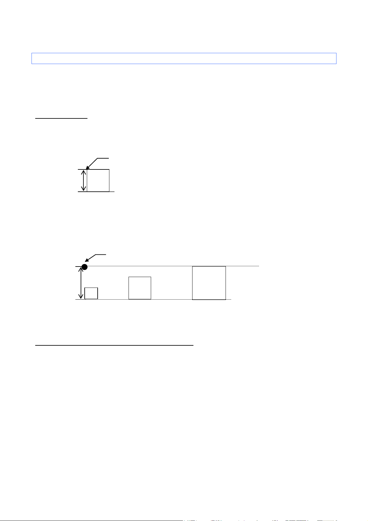
3.3 Print position
The print position is the standard position for printing characters, bitmaps and bar codes.
With the print position, there is a horizontal print position, which is the reference point for vertical position
movement.
3.3.1 Characters
Each character is arranged so that their top edge aligns with the print position.
The baseline of each character is the bottom edge of the character, regardless of size, font, etc.
All characters on the same line are printed so that the baseline position is the same for each character.
If the text consists of characters with different heights, the characters are aligned on the baseline of the tallest
character in the line of text.
In addition, underlines are printed 4 dots below the baseline position.
3.3.2 Bitmaps, barcodes and downloaded images
These types of image data are treated in the same way as characters and are printed so that the bottom edge
of the image aligns with the baseline.
A
- 12 -
3. ESC/P Command Limitations
Page 18

ESC/P Command Reference
Line feed amount
3.4 Line feed amount
The line feed amount is the amount of vertical movement from the print position of one line to the print of the
next line.
HHHHHHHHHHHHH
HHHHHHHHHHHHH
HHHHHHHHHHHHH
The line feed amount is specified using ESC 0, ESC 2, ESC A and ESC 3.
- 13 -
3. ESC/P Command Limitations
Page 19

ESC/P Command Reference
ASCII Code
Binary Code
Description
ESC R
1B 52
Select international character set
ESC k
1B 6B
Select font
ESC t
1B 74
Select character code table
ASCII Code
Binary Code
Description
ESC 4
1B 34
Apply italic style
ESC 5
1B 35
Cancel italic style
ESC E
1B 45
Apply bold style
ESC F
1B 46
Cancel bold style
ESC G
1B 47
Apply double-strike printing
ESC H
1B 48
Cancel double-strike printing
ESC W
1B 57
Specify double-width characters
SI
0F
Specify compressed characters
ESC SI
1B 0F
Specify compressed characters
DC2
12
Cancel compressed characters
ESC -
1B 2D
Apply/cancel underlining
ESC !
1B 21
Global formatting
ESC X
1B 58
Specify character size
ESC if
1B 69 66
Apply/cancel a frame (global)
CAN
18
Clear text
DEL
7F
Delete one character
ESC CR
1B 0D
Not available
ASCII Code
Binary Code
Description
ESC 0
1B 30
Specify line feed of 1/8 inch
ESC 2
1B 32
Specify line feed of 1/6 inch
ESC 3
1B 33
Specify minimum line feed
ESC A
1B 41
Specify line feed of n/60 inch
4. Control Code List
Character/style selection commands (Refer to section 5.1 Character/style selection commands.)
Text printing commands (Refer to section 5.2 Text printing commands)
Line feed commands (Refer to section 5.3 Line feed commands.)
- 14 -
4. Control Code List
Page 20

ASCII Code
Binary Code
Description
CR
0D
Carriage return
ESC $
1B 24
Specify absolute horizontal position
ESC \
1B 5C
Specify relative horizontal position
ESC a
1B 61
Specify alignment
ASCII Code
Binary Code
Description
LF
0A
Line feed
FF
0C
Page feed
ESC J
1B 4A
Forward paper feed
ASCII Code
Binary Code
Description
ESC i l
1B 69 6C
Specify label length
ESC i m
1B 69 6D
Specify margin width
ASCII Code
Binary Code
Description
ESC @
1B 40
Initialize
ASCII Code
Binary Code
Description
ESC *
1B 2A
Select bit image
ESC K
1B 4B
8-dot single-density bit image
ESC L
1B 4C
8-dot double-density bit image
ESC Y
1B 59
8-dot double-speed double-density bit image
ESC Z
1B 5A
8-dot quadruple-density bit image
Horizontal movement comm ands (Refer to section 5.4 Horizontal movement commands.)
Vertical movement commands (Refer to section 5.5 Vertical movement commands.)
Paper formatting commands (Refer to section 5.6 Paper formatting commands.)
ESC/P Command Reference
Printer control comm ands (Refer to section 5.7 Printer control commands.)
Graphics commands (Refer to section 5.8 Graphics commands.)
- 15 -
4. Control Code List
Page 21

ASCII Code
Binary Code
Description
ESC i B
1B 69 42
Barcode
ESC i Q
1B 69 51
2D bar code (QR Code)
ESC i P
1B 69 50
Specify QR Code version
ESC i V
1B 69 56
2D bar code (PDF417)
ESC i D
1B 69 44
2D bar code (DataMatrix)
ESC i M
1B 69 4D
2D bar code (MaxiCode)
ESC i J
1B 69 4A
2D barcode (AztecCode)
ESC i F
1B 69 46
Print transferred data
ESC i a
1B 69 61
Switch command mode
ESC i S
1B 69 53
Request printer status
ESC i L
1B 69 4C
Apply/cancel rotated printing
ESC i C
1B 69 43
Specify cut setting
ESC i UB
1B 69 55 42
Specify baud rate
ESC i Ub
1B 69 55 62
Specify bit length
ESC i UP
1B 69 55 50
Specify parity setting
ESC i UC
1B 69 55 43
Specify busy control
ASCII Code
Binary Code
Description
ESC iXE2
1B 69 58 45 32
Specify barcode margin setting
ESC iXE1
1B 69 58 45 31
Retrieve barcode margin setting
Advanced commands (Refer to section 5.9 Advanced commands.)
ESC/P Command Reference
Advanced static commands (Refer to section 5.10 Advanced static commands.)
- 16 -
4. Control Code List
Page 22

ESC/P Command Reference
n=0:
U.S.A
n=1:
France
n=2:
Germany
n=3:
UK
n=4:
Denmark I
n=5:
Sweden
n=6:
Italy
n=7:
Spain I
n=8:
Japan
n=9:
Norway
n=10:
Denmark II
n=11:
Spain II
n=12:
Latin America
n=13:
South Korea
n=64:
Legal
5. Control Command Details
5.1 Character/style selection commands
ESC R Select international character set
ASCII: ESC R n
Decim al: 27 82 n
Hexadecimal: 1B 52 n
Parameters
0≤n≤13, 64
Description
Selects the character set for the country, and switches some character codes in the code table according to
the value of n.
The following 12 codes are changed.
The default setting is n=0 (USA) for overseas.
When using the standard character code table, printing is performed according to the specified international
Example
23h, 24h, 40h, 5Bh, 5Ch, 5Dh, 5Eh, 60h, 7Bh, 7Ch, 7Dh, 7Eh
character set.
Code: 5Ch ESC R 08h 5Ch FF
Print result: \¥
- 17 -
5. Control Command Details
Page 23

Bitmap fonts
n=0 Helsinki
n=1 Letter Gothic
ESC k Select font
ASCII: ESC k n
Decim al: 27 107 n
Hexadecimal: 1B 6B n
Parameters
0≤n≤1
Description
Selects the font.
The default value is n=0 (Helsinki).
ESC/P Command Reference
- 18 -
5. Control Command Details
Page 24

ESC/P Command Reference
n=0:
Standard character code table
n=1:
Eastern European character code table
n=2:
Western European character code table
n=3:
(Spare)
ESC t Select character code table
ASCII: ESC t n
Decim al: 27 116 n
Hexadecimal: 1B 74 n
Parameters
n=0, 1, 2
Description
From the three built-in character code tables, select the character code table to be used.
The default setting is n=0.
- 19 -
5. Control Command Details
Page 25

5.2 Text printing commands
ESC 4 Apply italic style
ASCII: ESC 4
Decim al: 27 52
Hexadecimal: 1B 34
Parameters
None
Description
Applies the italic style to the following text.
ESC/P Command Reference
ESC 5 Cancel italic style
ASCII: ESC 5
Decim al: 27 53
Hexadecimal: 1B 35
Parameters
None
Description
Cancels the italic style.
Example
Code: ABC ESC 4 DEF ESC 5 GHI FF
Print result: ABCDEFGHI
- 20 -
5. Control Command Details
Page 26

ESC E Apply bold style
ASCII: ESC E
Decim al: 27 69
Hexadecimal: 1B 45
Parameters
None
Description
Prints the following text in bold.
ESC F Cancel bold style
ASCII: ESC F
ESC/P Command Reference
Decim al: 27 70
Hexadecimal: 1B 46
Parameters
None
Description
Cancels the bold style.
Example
Code: ABC ESC E DEF ESC F GHI FF
Print result: ABCDEFGHI
- 21 -
5. Control Command Details
Page 27

ESC G Apply double-strike printing
ASCII: ESC G
Decim al: 27 71
Hexadecimal: 1B 47
Parameters
None
Description
Prints the following text in bold.
ESC H Cancel double-strike printing
ASCII: ESC H
ESC/P Command Reference
Decim al: 27 72
Hexadecimal: 1B 48
Parameters
None
Description
Cancels the bold style.
Example
Code: ABC ESC E DEF ESC F GHI FF
Print result: ABCDEFGHI
- 22 -
5. Control Command Details
Page 28

n=1 or 49 (“1”):
Double-width characters are specified.
n=0 or 48 (“0”):
Double-width characters are cancelled.
ESC W Specify double-width characters
ASCII: ESC W n
Decim al: 27 87 n
Hexadecimal: 1B 57 n
Parameters
n=0 and 1 or 48 and 49
Description
Specifies double-width characters.
Example
Code: ABC ESC W 1 ABC ESC W 0 ABC FF
ESC/P Command Reference
Print result: ABC
ABC
ABC
- 23 -
5. Control Command Details
Page 29

SI Specify compressed characters
ASCII: SI
Decim al: 15
Hexadecimal: 0F
Parameters
None
Description
Prints the following text in half-width characters.
ESC SI Specify compressed characters
ESC/P Command Reference
ASCII: ESC SI
Decim al: 27 15
Hexadecimal: 1B 0F
Parameters
None
Description
Same as SI
DC2 Cancel compressed characters
ASCII: DC2
Decim al: 18
Hexadecimal: 12
Parameters
None
Description
Cancels compressed characters specified with SI.
- 24 -
5. Control Command Details
Page 30

n=1:
Underlining is applied.
n=0:
Underlining is cancelled.
ESC – Apply/cancel underlining
ASCII: ESC - n
Decim al: 27 45 n
Hexadecimal: 1B 2D n
Parameters
n=0 and 1 or 48 and 49
Description
Applies or cancels underlining.
The underlining specified by this code is a continuous line.
Spaces between characters and words are also underlined.
ESC/P Command Reference
Example
Code: ABC ESC - 1 ABC ESC - 0 ABC FF
Print result: ABCABCABC
- 25 -
5. Control Command Details
Page 31

Bit 7 6 5 4 3 2 1 0
1
Underline
Italics
Not used
Bold
Bold
Not used
Not used
Not used
0
Cancel
Cancel
Not used
Cancel
Cancel
Not used
Not used
Not used
ESC ! Global formatting
ASCII: ESC ! n
Decim al: 27 33 n
Hexadecimal: 1B 21 n
Parameters
0≤n≤255
Description
Specifies a combination of the various print modes.
Specifies modes according to the bit value of n.
A combination of multiple print modes can be specified at one time.
ESC/P Command Reference
Example
To apply underlining and the italic style at one time
Code: ABC ESC ! C0h ABC ESC ! 00h ABC FF
Print result: ABC
ABC
ABC
- 26 -
5. Control Command Details
Page 32

n=0 (or 30h):
The AUTO size is applied.
n=1 (or 31h):
The 4-point size is applied. (21 dots)
n=2 (or 32h):
The 6-point size is applied. (28 dots)
n=3 (or 33h):
The 9-point size is applied. (44 dots)
n=4 (or 34h):
The 12-point size is applied. (56 dots)
n=5 (or 35h):
The 18-point size is applied. (88 dots)
n=6 (or 36h):
The 24-point size is applied. (120 dots)
ESC X Specify character size
ASCII: ESC X n
Decim al: 27 88 n
Hexadecimal: 1B 58 n
Parameters
0≤n≤6 or 30h≤n≤36h
Description
Specifies the character size.
The character size can be set to AUTO or a fixed size (six sizes).
ESC/P Command Reference
- 27 -
5. Control Command Details
Page 33

n=0 (or 30h):
The frame is cancelled.
n=1 (or 31h):
A frame is applied.
ESC if Apply/cancel a frame
ASCII: ESC i f
Decim al: 27 105 102
Hexadecimal: 1B 69 66
Parameters
0≤n≤1 or 30h≤n≤31h
Description
Applies a frame around the entire text.
ESC/P Command Reference
CAN Clear text
ASCII: CAN
Decim al: 24
Hexadecimal: 18
Parameters
None
Description
Clears all text, image data and bar codes that were received.
- 28 -
5. Control Command Details
Page 34

DEL Delete one character
ASCII: DEL
Decim al: 127
Hexadecimal: 7F
Parameters
None
Description
The immediately preceding character within the same line is deleted.
If the immediately preceding data is a bar code, the bar code is deleted.
Image data is not deleted.
ESC/P Command Reference
ESC CR Not available
ASCII: ESC CR n
Decim al: 27 13 n
Hexadecimal: 1B 0D n
Parameters
0≤n≤255
Description
Does nothing.
- 29 -
5. Control Command Details
Page 35

5.3 Line feed commands
ESC 0 Specify line feed of 1/8 inch
ASCII: ESC 0
Decim al: 27 48
Hexadecimal: 1B 30
Parameters
None
Description
Specifies a line feed of 1/8 inch (approximately 0.32 cm).
ESC/P Command Reference
ESC 2 Specify line feed of 1/6 inch
ASCII: ESC 2
Decim al: 27 50
Hexadecimal: 1B 32
Parameters
None
Description
Specifies a line feed of 1/6 inch (approximately 0.42 cm).
- 30 -
5. Control Command Details
Page 36

ESC 3 Specify line feed of n/180 inch
ASCII: ESC 3 n
Decim al: 27 51 n
Hexadecimal: 1B 33 n
Parameters
0≤n≤255
Description
Specifies a line feed of n/180 inch per text line.
If n is less than 24, the line feed amount is set to 24/180 inch (approximately 0.34 cm).
ESC A Specify line feed of n/60 inch
ESC/P Command Reference
ASCII: ESC A n
Decim al: 27 65 n
Hexadecimal: 1B 41 n
Parameters
0≤n≤255
Description
Specifies a line feed of n/60 inch per text line.
If n is less than 8, the line feed amount is set to 8/60 inch (approximately 0.34 cm).
- 31 -
5. Control Command Details
Page 37

ESC/P Command Reference
5.4 Horizontal movement commands
CR Carriage return
ASCII: CR
Decim al: 13
Hexadecimal: 0D
Parameters
None
Description
Performs a line feed of the amount specified by a line feed command (ESC 0, ESC 2, ESC 3 and ESC A).
If no line feed amount has been specified, it is automatically specified depending on the width of the tape.
The next print position is the beginning of the next line.
A line feed command immediately after a carriage return is ignored.
- 32 -
5. Control Command Details
Page 38

ESC/P Command Reference
ESC $ Specify absolute horizontal position
ASCII: ESC $ n1 n2
Decim al: 27 36 n1 n2
Hexadecimal: 1B 24 n1 n2
Parameters
0≤n1≤255, 0≤n2≤255
Description
Specifies an absolute print position (in units of 1/60 inch) for the next data.
An absolute print position specifies the horizontal print position from the left margin.
The next character is printed at a position (n1 + 256 * n2) / 60 inch from the left margin.
The maximum number of dots can be specified by both n1 and n2 is 1023/60 inches.
ESC \ Specify relative horizontal position
ASCII: ESC \ n1 n2
Decim al: 27 92 n1 n2
Hexadecimal: 1B 5C n1 n2
Parameters
0≤n1≤255, 0≤n2≤255
Description
Specifies a relative print position (in units of 1/180 inch) for the next data.
A relative print position specifies the horizontal print position based on the current position.
The next character is printed at a position (n1 + 256 * n2) / 180 inch from the current position.
A relative position cannot be specified to the left (in the negative direction).
The maximum number of dots can be specified by both n1 and n2 is 16383/180 inches.
This command is available only with left alignment.
- 33 -
5. Control Command Details
Page 39

ESC/P Command Reference
n=0:
specifies left alignment.
n=1:
specifies center alignment.
n=2:
specifies right alignment.
n=3:
specifies justified alignment.
ESC a Specify alignment
ASCII: ESC a n
Decim al: 27 97 n
Hexadecimal: 1B 61 n
Parameters
0≤n≤3 or “0”≤n≤”3”
Description
The following data is printed with the alignment described below, depending on the value of n.
The default setting is n=0.
The last alignment setting received is applied to all of the print data.
If an absolute horizontal position or a relative horizontal position is specified, the text must be aligned on the
left when it is printed.
- 34 -
5. Control Command Details
Page 40

5.5 Vertical movement commands
LF Line feed
ASCII: LF
Decim al: 10
Hexadecimal: 0A
Parameters
None
Description
Performs the same line feed operation as CR.
A carriage return command immediately after a line feed is ignored.
ESC/P Command Reference
FF Page feed
ASCII: FF
Decim al: 12
Hexadecimal: 0C
Parameters
None
Description
Starts printing.
Clears the text, image data and bar codes after printing.
If the data does not fit within the printable height of the tape, the data is divided and printed onto multiple
pages.
If the length of the print data exceeds 1 meter, the LED lights up to indicate that an error has occurred.
- 35 -
5. Control Command Details
Page 41

ESC/P Command Reference
ESC J Forward paper feed
ASCII: ESC J n
Decim al: 27 74 n
Hexadecimal: 1B 4A n
Parameters
0≤n≤255
Description
Finishes input of the current line, then moves the vertical print position forward by n/180 inch.
If n is less than 24, the feed amount is 24/180 inch (approximately 0.34 cm).
- 36 -
5. Control Command Details
Page 42

5.6 Paper formatting commands
ESC il Specify label length
ASCII: ESC i l n1 n2
Decim al: 27 105 108 n1 n2
Hexadecimal: 1B 69 6C n1 n2
Parameters
len=n1+n2x256
(len=0 or 36≤len≤7200)
Description
Specifies the label length (len) in units of 1/180 inch.
The range in which the label length can be set is 0.2 to 40 inches.
ESC/P Command Reference
len=0 specifies the AUTO setting.
ESC im Specify margin width
ASCII: ESC i m n1 n2
Decim al: 27 105 109 n1 n2
Hexadecimal: 1B 69 6D n1 n2
Parameters
mgn=n1+n2x256
(7≤mgn≤720)
Description
Specifies the margin width (mgn) in units of 1/180 inch.
The range in which the margin width can be set is 0.04 to 4 inches.
- 37 -
5. Control Command Details
Page 43

Command mode
Template)
Communication settings
(Baud rate, Parity, Bit length and
Busy control)
5.7 Printer control commands
ESC @ Initialize
ASCII: ESC @
Decim al: 27 64
Hexadecimal: 1B 40
Parameters
None
Description
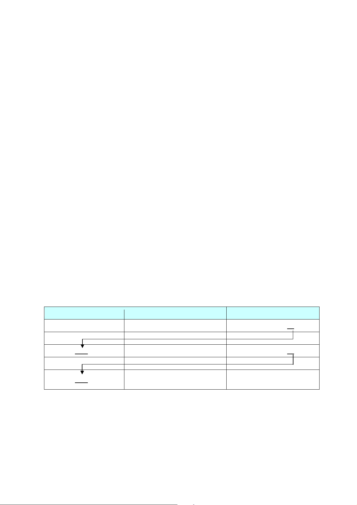
Resets all parameters to their default settings. (See below.)
Item After Initialization
ESC/P Command Reference
(ESC/P, Raster or P-touch
No change
No change
Received text and bar codes Cleared
Received image data Cleared
Line feed amount AUTO
Relative position setting Cleared
Absolute position setting Cleared
Font Helsinki
Character size AUTO
Italics OFF
Bold/double-strike printing OFF
Underline OFF
Character width Normal (Half-width and double-width characters are cancelled.)
Character code table Standard character code table
International character set USA
Frame None
Rotate OFF
Text alignment Left
Margins 2 mm
Label length setting AUTO
Bar code protocol CODE39
- 38 -
5. Control Command Details
Page 44

Item After Initialization
Bar code width Small
Bar code ratio 3:1
Bar code check digit OFF
Characters below bar codes ON
Full cut ON
Half cut ON
Chain printing OFF
ESC/P Command Reference
- 39 -
5. Control Command Details
Page 45

n1:
The remainder from dividing the number of dot positions by 256
n2:
The quotient from dividing the number of dot positions by 256
Horizontal Dot
Density
Vertical Dot
Density
Horizontal Dot
Resolution
Vertical Dot
Resolution
0
60 dpi
60 dpi
6/360 inch
6/360 inch
1
120 dpi
60 dpi
3/360 inch
6/360 inch
2
120 dpi
60 dpi
3/360 inch
6/360 inch
3
240 dpi
60 dpi
2/360 inch
6/360 inch
4
80 dpi
60 dpi
4/360 inch
6/360 inch
6
90 dpi
60 dpi
4/360 inch
6/360 inch
32
60 dpi
180 dpi
6/360 inch
2/360 inch
33
120 dpi
180 dpi
3/360 inch
2/360 inch
38
90 dpi
180 dpi
4/360 inch
2/360 inch
39
180 dpi
180 dpi
2/360 inch
2/360 inch
40
360 dpi
180 dpi
1/360 inch
2/360 inch
71
180 dpi
360 dpi
2/360 inch
1/360 inch
72
360 dpi
360 dpi
1/360 inch
1/360 inch
73
360 dpi
360 dpi
1/360 inch
1/360 inch
5.8 Graphics commands
ESC * Select bit image
ASCII: ESC * m n1 n2 data
Decim al: 27 42 m n1 n2 data
Hexadecimal: 1B 2A m n1 n2 data
Parameters
m=0, 1, 2, 3, 4, 6, 32, 33, 38, 39, 40, 71, 72 or 73
0≤n1≤255, 0≤n2≤255
The data contains image data that is n1 + n2 * 256 bytes when m=0, 1, 2, 3, 4 or 6,
(n1 + n2 * 256) * 3 bytes when m=32, 33, 38, 39 or 40,
or (n1 + n2 * 256) * 6 bytes when m=71, 72 or 73.
ESC/P Command Reference
Description
Selects and outputs a bit image according to the value of m.
n1 and n2 indicate the number of dot positions.
m
- 40 -
5. Control Command Details
Page 46
n1:
The remainder from dividing the number of dot positions by 256
n2:
The quotient from dividing the number of dot positions by 256
1 byte
1 byte
1 byte
1 byte … 1 byte
1 byte
n1+n2*256 byte
MSB
LSM
B7
B6
B5
B4
B3
B2
B1
B0
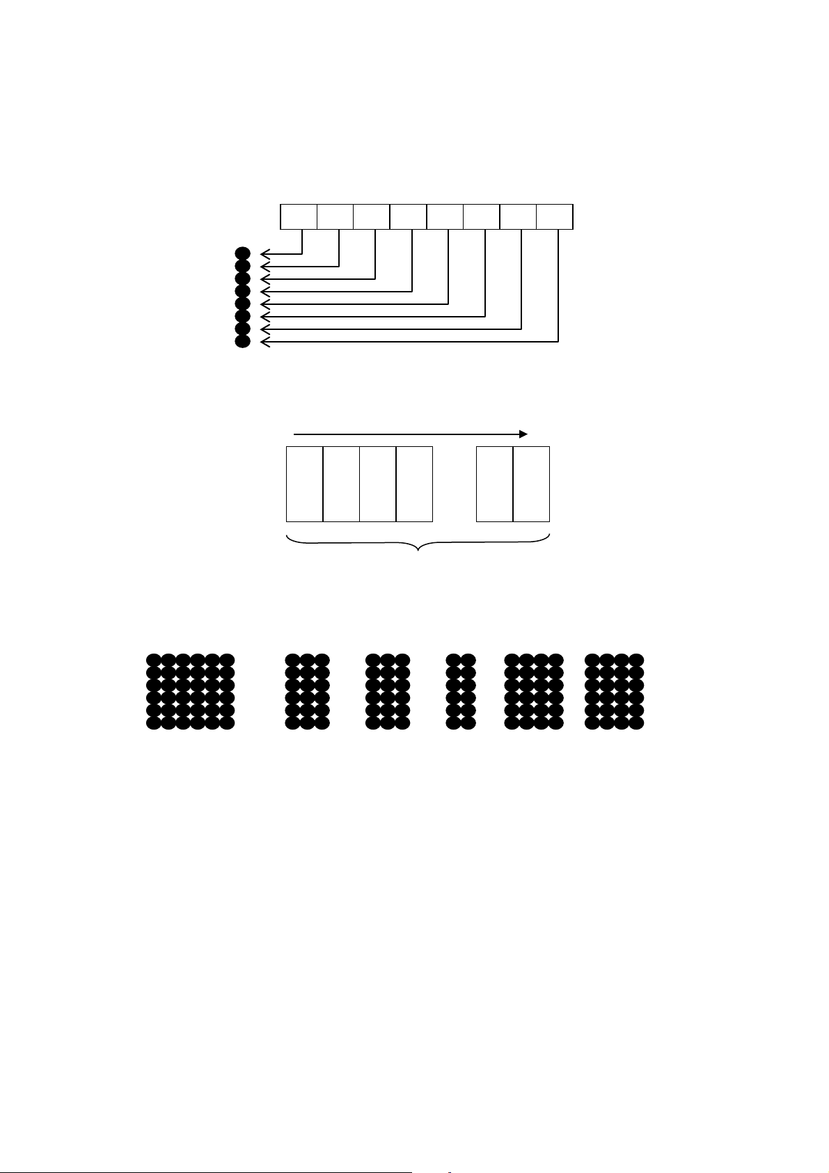
When m=0, 1, 2, 3, 4 or 6
n1 and n2 indicate the number of dot positions.
Relationship between the image data and the dots
First, the data is lined up in one row as shown below.
ESC/P Command Reference
One dot of the image data is enlarged according to the value of m, as shown below.
m=0 m=1 m=2 m=3 m=4 m=6
As a result, the image is sized depending on the value of m, as shown below.
m=0 48 dots vertically × (n1 + n2 * 256) * 6 dots horizontally
m=1 48 dots vertically × (n1 + n2 * 256) * 3 dots horizontally
m=2 48 dots vertically × (n1 + n2 * 256) * 3 dots horizontally
m=3 48 dots vertically × (n1 + n2 * 256) * 2 dots horizontally
m=4 48 dots vertically × (n1 + n2 * 256) * 4 dots horizontally
m=6 48 dots vertically × (n1 + n2 * 256) * 4 dots horizontally
- 41 -
5. Control Command Details
Page 47
n1:
The remainder from dividing the number of dot positions by 256
n2:
The quotient from dividing the number of dot positions by 256
B7 B6 B5 B4 B3 B2 B1 B0 B7 B6 B5 B4 B3 B2 B1 B0 B7 B6 B5 B4 B3 B2 B1 B
0
1st byte
2nd byte
3rd byte
1 byte
1 by te
1 by te
1 by te
1 by te
1 by te
(n1+n2*256)*3 byte
MSB
LSM
1 by te
1 by te
1 by te
1 by te
1 by te
1 by te
MSB
LSM
1 by te
1 by te
1 by te
1 by te
1 by te
1 by te
MSB
LSM
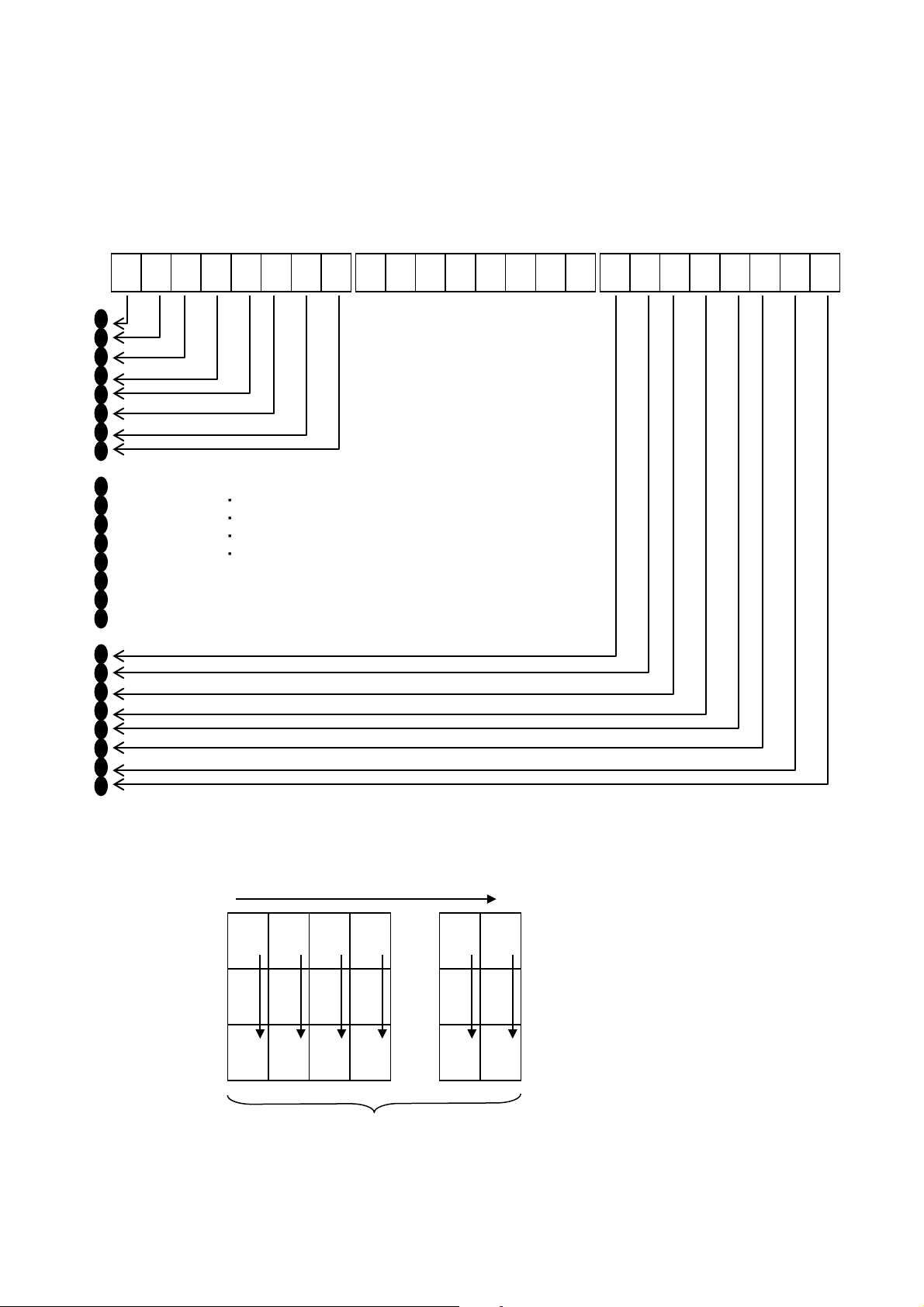
When m=32, 33, 38, 39 or 40
n1 and n2 indicate the number of dot positions.
ESC/P Command Reference
・ ・ ・ ・ ・
・
・
・
・
Relationship between the image data and the dots
First, the data is lined up in three rows as shown below.
- 42 -
5. Control Command Details
Page 48

m=32
m=33
m=38
m=39
m=40
One dot of the image data is enlarged according to the value of m, as shown below.
As a result, the image is sized depending on the value of m, as shown below.
m=32 48 dots vertically × (n1 + n2 * 256) * 6 dots horizontally
m=33 48 dots vertically × (n1 + n2 * 256) * 3 dots horizontally
m=38 48 dots vertically × (n1 + n2 * 256) * 4 dots horizontally
m=39 48 dots vertically × (n1 + n2 * 256) * 2 dots horizontally
m=40 48 dots vertically × (n1 + n2 * 256) * 4 dots horizontally
ESC/P Command Reference
- 43 -
5. Control Command Details
Page 49

n1:
The remainder from dividing the number of dot positions by 256
n2:
The quotient from dividing the number of dot positions by 256
B7 B6 B5 B4 B3 B2 B1 B0 B7 B6 B5 B4 B3 B2 B1 B0 B7 B6 B5 B4 B3 B2 B1 B
0
1st byte
2nd to 5th bytes
6th byte
When m=71, 72 or 73
n1 and n2 indicate the number of dot positions. Specify their values as shown below.
・ ・ ・ ・ ・
ESC/P Command Reference
・
・
・
・
Relationship between the image data and the dots
- 44 -
5. Control Command Details
Page 50

m=71
m=72
m=73
1 by te
1 by te
1 by te
1 by te
1 by te
1 by te
MSB
LSM
1 by te
1 by te
1 by te
1 by te
1 by te
1 by te
MSB
1 by te
1 by te
1 by te
1 by te
1 by te
1 by te
LSM
1 by te
1 by te
1 by te
1 by te
1 by te
1 by te
LSM
1 by te
1 by te
1 by te
1 by te
1 by te
1 by te
MSB
1 by te
1 by te
1 by te
1 by te
1 by te
1 by te
MSB
LSM
First, the data is lined up in six rows as shown below.
ESC/P Command Reference
LSM
MSB
LSM
One dot of the image data is enlarged according to the value of m, as shown below.
As a result, the image is sized depending on the value of m, as shown below.
m=71 48 dots vertically × (n1 + n2 * 256) * 2 dots horizontally
m=72 48 dots vertically × (n1 + n2 * 256) * 1 dot horizontally
m=73 48 dots vertically × (n1 + n2 * 256) * 1 dot horizontally
- 45 -
5. Control Command Details
Page 51

ESC/P Command Reference
n1:
The remainder from dividing the number of dot positions by 256
n2:
The quotient from dividing the number of dot positions by 256
B7
B6
B5
B4
B3
B2
B1
B0
1 byte
1 byte
1 byte
1 byte … 1 byte
1 byte
n1+n2*256 byte
MSB
LSM
ESC K 8-dot single-density bit image
ASCII: ESC K n1 n2 data
Decim al: 27 75 n1 n2 data
Hexadecimal: 1B 4B n1 n2 data
Parameters
0≤n1≤255, 0≤n2≤255
The data contains image data that is n1 + n2 * 256 bytes.
Description
Specifies that an 8-dot standard-density bit image will be printed with the number of dot positions defined by
n1 and n2.
n1 and n2 indicate the number of dot positions.
Relationship between the image data and the dots
First, the data is lined up in one row as shown below.
One dot of the image data is enlarged to 6 dots vertically by 6 dots horizontally.
- 46 -
5. Control Command Details
Page 52

ESC/P Command Reference
As a result, the image becomes 48 dots vertically × (n1 + n2 * 256) * 6 dots horizontally.
- 47 -
5. Control Command Details
Page 53

ESC/P Command Reference
1 byte
1 byte
1 byte
1 byte … 1 byte
1 byte
n1+n2*256 byte
MSB
LSM
ESC L 8-dot double-density bit image
ASCII: ESC L n1 n2 data
Decim al: 27 76 n1 n2 data
Hexadecimal: 1B 4C n1 n2 data
Parameters
0≤n1≤255, 0≤n2≤255
The data contains image data that is n1 + n2 * 256 bytes.
Description
Specifies that an 8-dot double-density bit image will be printed with the number of dot positions defined by n1
and n2.
Specify n1 and n2 in the same way as with ESC K.
First, the data is lined up in one row as shown below.
One dot of the image data is enlarged to 6 dots vertically by 3 dots horizontally.
As a result, the image becomes 48 dots vertically × (n1 + n2 * 256) * 3 dots horizontally.
- 48 -
5. Control Command Details
Page 54

ESC/P Command Reference
1 byte
1 byte
1 byte
1 byte … 1 byte
1 byte
n1+n2*256 byte
MSB
LSM
ESC Y 8-dot double-speed double-density bit image
ASCII: ESC Y n1 n2 data
Decim al: 27 89 n1 n2 data
Hexadecimal: 1B 59 n1 n2 data
Parameters
0≤n1≤255, 0≤n2≤255
The data contains image data that is n1 + n2 * 256 bytes.
Description
Specifies that an 8-dot double-speed double-density bit image will be printed with the number of dot
positions defined by n1 and n2.
Specify n1 and n2 in the same way as with ESC K.
ESC Z 8-dot quadruple-density bit image
ASCII: ESC Z n1 n2 data
Decim al: 27 90 n1 n2 data
Hexadecimal: 1B 5A n1 n2 data
Parameters
0≤n1≤255, 0≤n2≤255
The data contains image data that is n1 + n2 * 256 bytes.
Description
Specifies that an 8-dot double-density bit image will be printed with the number of dot positions defined by n1
and n2.
Specify n1 and n2 in the same way as with ESC K.
First, the data is lined up in one row as shown below.
One dot of the image data is enlarged to 6 dots vertically by 2 dots horizontally.
- 49 -
5. Control Command Details
Page 55

ESC/P Command Reference
As a result, the image becomes 48 dots vertically × (n1 + n2 * 256) * 2 dots horizontally.
- 50 -
5. Control Command Details
Page 56

T or t (type)
t0: CODE39
te: POSTNET
s (style)
Ignored
p (number of passes)
Ignored
R or r
(characters below barcode)
r0: OFF
r1: ON
u (units of measurement)
Ignored
x (horizontal position)
Ignored
y (vertical offset)
Ignored
5.9 Advanced commands
ESC i B Barcode
ASCII: ESC i [Parameters] B or b [Barcode data] Backslash
Decim al: 27 105 [Parameters] 66 or 98 [Barcode data] 92
Hexadecimal: 1B 69 [Parameters] 42 or 62 [Barcode data] 5C
Format: ESC i [Parameters] B or b [Barcode data] Backslash
(1) (2) (3) (4)
Parameters
(1) [Parameters] : Barcode parameters
t1: ITF (I-2/5)
t2: EAN-13
t3: EAN-8
t4: UPC-A
t5: EAN-8 (when the bar code data contains 7 characters)
UPC-A (when the bar code data contains 11 characters)
EAN-13 (when the bar code data contains 12 characters)
* The check digit mark “?” is not included in the number of
characters.
t6: UPC-E
t9: CODABAR
ta: CODE128
tb: GS1-128 (UCC/EAN-128)
tc: RSS symbols
ESC/P Command Reference
- 51 -
5. Control Command Details
Page 57

ESC/P Command Reference
h (height)
h n1 n2
If height > 454, height = 454.
However, with tc, the height is as described below.
If height > max., height = max.
w
w0: small
w2: large
E or e
(parentheses removed)
e0: ON
e1: OFF
o
o0: RSS-14 Standard
o6: RSS Expanded Stacked
c
Expanded Stacked)
c: No. of horizontal characters
z
thin bars)
z0: (3:1)
z2: (2:1)
Height = n1 + n2 * 256 (dots)
48 ≤ height ≤ 454
If height < 48, height = 48.
141 ≤ height ≤ 454(RSS-14 Standard)
81 ≤ height ≤ 454 (RSS-14 Truncated)
81 ≤ height ≤ 454 (RSS-14 Stacked)
249 ≤ height ≤ 454 (RSS-14 Stacked Omni)
72 ≤ height ≤ 454 (RSS Limited)
144 ≤ height ≤ 454 (RSS Expanded)
If height < min., height = min.
(width)
(RSS symbols model)
w1: medium
o1: RSS-14 Truncated
o2: RSS-14 Stacked
o3: RSS-14 Stacked Omnidirectional
o4: RSS Limited
o5: RSS Expanded Standard
(number of horizontal
This must be an even value where 2 ≤ no. of horizontal characters ≤ 20.
characters for RSS
(ratio between thick and
z1: (2.5:1)
(A barcode with a large number of stacked rows may be considered out of specifications and
unreadable by the reader.)
- 52 -
5. Control Command Details
Page 58

ESC/P Command Reference
t0:
1 to 50 characters (not including “*” on both sides)
t1:
1 to 64 characters
t5:
7 characters (EAN-8)
11 characters (UPC-A)
t6:
6 characters
t9:
3 to 64 characters (with “A”, “B”, “C” or “D” at the beginning and end)
ta:
1 to 64 characters
tb:
1 to 64 characters
tc:
3 to 15 characters (begins with “01”) (except with RSS Expanded)
(numbers, letters, spaces, !, ”, %, &, ’, (, ), *, +, ,, -, ., /, :, ;, <, =, >, ? and _)
te:
5 characters, 9 characters, 11 characters
Note
* Both 00H through 09H and 30H through 39H are recognized as the parameter numbers 0 through 9.
* Parameter types a and b are recognized, even if they are uppercase letters.
* The parameter "parentheses removed" is available only when GS1-128 (UCC/EAN-128) is selected.
* The parameter “ratio between thick and thin bars” is available only when t0, t1 or t9 is selected.
* If there is no type command or if an invalid type command has been specified, Code 39 is specified.
* The number of characters that can be entered for each barcode protocol is listed below.
12 characters (EAN-13)
1 to 64 numbers or 1 to 40 letters* (for RSS Expanded)
* ISO646 characters can be printed.
(2) B or b: Beginning of barcode data
(3) [Barcode data]: Data for the barcode
? (Generate check digit) :
Generates a check digit when “?” is in the bar code data
The position of “?” is irrelevant as long as it is within the barcode data.
With POSTNET, CODE128 and GS1-128 (UCC/EAN-128) , no check digit is generated.
If “?” is inserted, it is treated as barcode data.
- 53 -
5. Control Command Details
Page 59

Barcode Type
Co mmand
POSTNET, CODE39 , ITF(I-2/5) , EAN-8 ,
sybols
CODE128,
GS1-128 (UCC/EAN-128)]
(4) [Backslash]: End of barcode data
ESC/P Command Reference
EAN-13 , UPC-A , UPC-E , CODABAR, RSS
ESC i [Parameter] B or b [Barcode data] \
ESC i [Parameter] B or b [Barcode data] \\\
Description
Specifies a barcode image.
Since the check digit is automatically generated from the barcode data, the check digit is not sent as
barcode data. Since the length of the barcode data is also checked, the data would not be correctly
recognized if check digit data is present.
With protocols CODE39, ITF (I-2/5), CODABAR, CODE128, GS1-128 (UCC/EAN-128) or RSS Expanded,
the buffer length for the barcode image is about 22 cm. A bar code longer than 22 cm will not be printed.
The characters that can be entered with CODE128 and GS1-128 (UCC/EAN-128) are the full 128 ASCII
characters and the special codes FNC1, FNC2, FNC3 and FNC4.
Codes assigned to the special codes
FNC1: 86h
FNC2: 81h
FNC3: 80h
FNC4: 84h
The control codes and special codes appear as spaces when characters are printed below CODE128 and
GS1-128 (UCC/EAN-128) barcodes.
Special code FNC1 can also be printed with RSS Expanded. This special code also appears as a space
when characters are printed below the barcode.
Code assigned to the special code
FNC1: 86h
Example
For data “123456789” with barcode type CODE39, with no characters printed below the barcode, a size of
large (width) × 454 dots (height), without parentheses, a ratio between thick and thin bars of 3:1, and bar
lengths not equalized, the command will be as shown below.
ESC i t0 r0 h C6h 01h w2 e1 z0 B 123456789 \
- 54 -
5. Control Command Details
Page 60

ESC/P Command Reference
1. Cell size
[1-byte decimal] 12
Specifies the dot size per cell side.
Prints 12 dots per cell side.
2. Symbol type
[1-byte decimal] 1
[1-byte decimal] 3
Model 1
Micro QR
3. Structured
[1-byte decimal] 0
Not partitioned. (default value)
4. Code number
[1-byte decimal] 1–16
Indicates the number of the symbol in a partitioned QR
Code.
5. Number of
partitions
[1-byte decimal] 2–16
Indicates the total number of symbols in a partitioned
QR Code.
6. Parity data
[1-byte hexadecimal]
Value (in bytes) of exclusively OR’ing all the print data
7. Error correction
[1-byte decimal] 1
[1-byte decimal] 4
High-density level: L 7%
Ultra-high-reliability level: H 30% (*2)
8. Data input
[1-byte decimal] 0
Auto input (default value)
entered.
ESC i Q 2D barcode (QR Code)
ASCII: ESC i Q or q Data
Decim al: 27 105 81 or 113 Data
Hexadecimal: 1B 69 51 or 71 Data
Format: ESC i Q or q [Parameters] [Barcode data] \\\
(1) (2) (3)
Parameters
(1) [Parameters]
Unlike with 1D barcodes, all parameters must be specified in order, starting from the top.
If a value other than those listed is entered for a parameter, that parameter is set to its default value.
Append setting
level
[1-byte decimal] 4
[1-byte decimal] 6
[1-byte decimal] 8
[1-byte decimal] 10
[1-byte decimal] 2
[1-byte decimal] 1
00-FF
[1-byte decimal] 2
[1-byte decimal] 3
Prints 4 dots per cell side. (default value)
Prints 6 dots per cell side.
Prints 8 dots per cell side.
Prints 10 dots per cell side.
Model 2 (default value)
Partitioned (*1)
(print data before partition)
Standard level: M 15% (default value)
High-reliability level: Q 25%
method
[1-byte decimal] 1
Manual input
Selects whether numbers, English alphanumeric
characters, kanji characters or binary characters are
- 55 -
5. Control Command Details
Page 61
ESC i Q or q [parameters for 1st set] [1st set of barcode data] \\\
ESC i Q or q [parameters for 3rd set] [3rd set of barcode data] \\\
3. Structured
This determines whether or not the barcode data is partitioned. If the data is not
ing, the values of 4 (code number), 5 (number of partitions), and
parameters.
4. Code number:
This indicates which number the ESC/P command for that QR Code is.
For example, if it is for the second of four partitions, this is 2; for the fourth this is 4.
5. Number of
partitions:
This is the number of partitions.
6. Parity data:
This is the value (in bytes) of exclusively OR’ing all the print data (print data before
command indicates that these codes are linked.
Character
OR’ed (XOR’ed) in bytes
Results
XOR of 0x31 and 0x32
0011 0001 ^= 0011 0010
0000 0011 (0x03)
XOR of 0x03 and 0x33
0000 0011 ^= 0011 0011
0011 0000 (0x30)
0000 0100 (0x04)
Therefore, the parity is 0x04.
(*1) With Micro QR, the linkage setting is invalid, and the default setting is used.
(*2) With Micro QR, error correction level 4 is invalid, and the default setting is used.
What is the QR Code Structured Append setting?
QR Codes have a linkage setting.
A long character string can be divided into 2 to 16 partitions and printed.
With ESC/P commands, it is necessary to enter only the number of partitions.
For example, if the print data is partitioned into 3 partitions, the barcode data is as follows:
ESC i Q or q [parameters for 2nd set] [2nd set of barcode data] \\\
Refer to the following for specifying settings for 3 through 6 in [Parameters].
ESC/P Command Reference
append setting:
partitioned, enter 0.
When not partition
6 (parity data) are ignored; therefore, enter 0 as a dummy value for these
partition). Entering the same value as for the partitioned QR Code ESC/P
What is exclusive OR’ing in bytes?
The data is exclusively OR’ed (XOR’ed) in bytes and in order.
For example, putting a character string into hexadecimal gives 31h, 32h, 33h, 34h.
XOR of 0x30 and 0x34 0011 0000 ^= 0011 0100
Note
If this parity value is incorrect, the correct QR Code is not generated.
- 56 -
5. Control Command Details
Page 62
ESC/P Command Reference
Without Structured
Append
With Structured
ESC i Q 0x04 0x02 0x01 0x01 0x03 0x31 0x02 0x00 “123” \\\
(The parity for the character string “123456789” is “0x31”.)
Barcode
Type
Preceded
Character
Number input
N or n
-
Alphanumeric
character input
Kanji character
input
ESC i Q [other parameters] 1 B0005##### \\\
B 0012 (0x30, 0x30, 0x31, 0x32)
Model 1
707 English alphanumeric characters, 1167 numbers, 486 binary bytes, 299 kanji
characters
Model 2
4296 English alphanumeric characters, 7089 numbers, 2953 binary bytes, 1817
kanji characters
Micro QR
21 English alphanumeric characters, 35 numbers, 15 binary bytes, 9 kanji
characters
Summary
Printing the character string “123456789” with a cell size of 4 dots, Model 2, standard error correction level,
and automatic data input
ESC i Q 0x04h 0x02h 0x00h 0x00h 0x00h 0x00h 0x02h 0x00h “123456789” \\\
Append
[Three partitions]
ESC i Q 0x04 0x02 0x01 0x02 0x03 0x31 0x02 0x00 “456” \\\
ESC i Q 0x04 0x02 0x01 0x03 0x03 0x31 0x02 0x00 “789” \\\
(2) [Barcode data]: Barcode data
When manual input is selected in 8 (data input method), the barcode data must be preceded with one of
the following single-byte alphanumeric characters.
Example
A or a ESC i Q [other parameters] 1 A012345678aBcDe \\\
K or k ESC i Q [other parameters] 1 K kanji character input \\\
Binary character
input
B or b+4-digit
number
With the “4-digit number”, specify the number of binary
characters to actually be entered. For example, if 12 binary
characters are to be entered, specify:
The number of barcode data characters that can be entered depends on the model type and the input
method.
Note
The numbers listed above are for an error correction level at a high-density level (L 7%).
If the standard level or higher is set, the number of characters that can be entered may decrease. In
addition, even if the characters are entered with the high-density level (L) specified, the number of
characters that can be entered may decrease due to compression.
- 57 -
5. Control Command Details
Page 63

(3) \\\: End of barcode
There must be three backslashes to end 2D barcode.
Example
Refer to the section “Summary”.
ESC/P Command Reference
- 58 -
5. Control Command Details
Page 64

ESC i P Specify QR Code version
ASCII: ESC i P n
Decim al: 27 105 80 n
Hexadecimal: 1B 69 50 n
Parameters
0≤n≤40
Description
The barcode size can be fixed.
The default value is “0”.
The available versions differ depending on the symbol type used.
If a setting other than those listed is specified, the setting returns to its default.
The following settings are available for each symbol type.
ESC/P Command Reference
MODEL1 (0 to 14), MODEL2 (0 to 40), Micro QR (0 to 4)
- 59 -
5. Control Command Details
Page 65

ESC/P Command Reference
1. Cell size
[1-byte decimal] 12
Specifies the dot size per cell side.
Prints 12 dots per cell side.
2. Symbol type
[1-byte decimal] 0
[1-byte decimal] 3
Standard (default value)
Micro PDF417 CODE128 emulation
3. Data input
1-byte decimal] 0
Auto input (default value)
4. Error correction
[1-byte decimal] 0
Level input (default value)
5. Error correction capacity-value
- Level input
[2-byte decimal] 0–8
Level input (default value of 0)
- Percentage input
[2-byte decimal] 0–400
Percentage input (default value of 0)
6. Symbol size (X
[1-byte decimal] 0
[1-byte decimal] 1–30
Auto setting (default value)
Manual settings
* 0 and 1–4 with MicroPDF417
7. Symbol size (Y
[1-byte decimal] 0
[1-byte decimal] 3–90
Auto setting (default value)
Manual settings
* 0 and 4–44 with MicroPDF417
ESC i V 2D barcode (PDF417)
ASCII: ESC i V or v data
Decim al: 27 105 86 or 118 data
Hexadecimal: 1B 69 56 or 76 data
Format: ESC i V or v [Parameters] [Barcode data] \\\
(1) (2) (3)
Parameters
(1) [Parameters]
Unlike with 1D barcodes, all parameters must be specified in order, starting from the top.
If a value other than those listed is entered for a parameter, that parameter is specified with its default
value.
method
capacity-type
direction)
[1-byte decimal] 4
[1-byte decimal] 6
[1-byte decimal] 8
[1-byte decimal] 10
[1-byte decimal] 1
[1-byte decimal] 2
[1-byte decimal] 1
[1-byte decimal] 1
Prints 4 dots per cell side. (default value)
Prints 6 dots per cell side.
Prints 8 dots per cell side.
Prints 10 dots per cell side.
Truncated
Micro PDF417 standard
Binary input
Percentage input
direction)
- 60 -
5. Control Command Details
Page 66

ESC/P Command Reference
8. Aspect value
Enter the aspect value. Actually, this is between
The default is “50”. (The actual value is 0.5.)
Symbol Size
(X Direction)
Symbol Size
(Y Direction)
AUTO
AUTO
1 AUTO
11
14
17
20
24
28
2 AUTO
8
11
14
17
20
23
26 3 AUTO
6 8 10
12
15
20
26
32
38
44
4 AUTO
4 6 8
10
12
15
20
26
32
38
44
[2-byte decimal] 1–1000
0.01 and 10.0. However, since a decimal point
cannot be entered, a value multiplied by 100 is
entered.
Note
* The aspect value setting is ignored if the symbol size in the X direction or the symbol size in the Y
direction is entered manually.
* Depending on the conditions, the bar code may not be generated or a bar code that cannot be
scanned may be generated if the symbol size in the X direction or the symbol size in the Y direction
is entered manually.
* When a large cell size is specified together with a high error correction capacity, printing may not
be possible because the print buffer has become full.
[With symbol type MicroPDF417]
* Since the error correction capacity is automatically determined from the symbol size in the X direction,
the settings for “Error correction capacity–type” and “Error correction capacity–value” are ignored.
* The aspect value setting is ignored.
* The following table shows the values available for the symbol size (Y direction) according to the
symbol size (X direction) setting. If an invalid setting is specified for the symbol size (Y direction), the
default setting is specified.
(2) [Barcode data]: Barcode data
The numbers of barcode data characters that can be entered are as follows.
1850 alphanumeric characters, 2710 numbers, 1108 binary bytes
Note
The numbers listed above are for an error correction level at a high-density level (L 7%). If the
standard level or higher is set, the number of characters that can be entered may decrease. In
addition, even if the characters are entered with the high-density level (L) specified, the number of
characters that can be entered may decrease due to compression.
- 61 -
5. Control Command Details
Page 67

ESC/P Command Reference
Maximum Amount of Information Allowed
Alphanumeric
Characters
Nu mbers
Binary
1
11 6 8
3
1
14
12
17
7
1
17
18
26
10
1
20
22
32
13
1
24
30
44
18
1
28
38
55
22
2 8 14
20
8
2
11
24
35
14
2
14
36
52
21
2
17
46
67
27
2
20
56
82
33
2
23
64
93
38
2
26
72
105
43
3 6 10
14
6
3 8 18
26
10
3
10
26
38
15
3
12
34
49
20
3
15
46
67
27
3
20
66
96
39
3
26
90
132
54
3
32
114
167
68
3
38
138
202
82
3
44
162
237
97
4 4 14
20
8
4 6 22
32
13
4 8 34
49
20
4
10
46
67
27
4
12
58
85
34
4
15
76
111
45
4
20
106
155
63
4
26
142
208
85
4
32
178
261
106
4
38
214
313
128
4
44
250
366
150
[With symbol type MicroPDF417]
Maximum of 250 alphanumeric characters, maximum of 366 numbers, maximum of 150 bytes of binary
data
However, the following table shows the maximum amount of information allowed according to the
settings for symbol size (X direction) and symbol size (Y direction).
X Y
(3) \\\: End of barcode
There must be three backslashes to end 2D barcodes.
- 62 -
5. Control Command Details
Page 68

ESC/P Command Reference
1. Cell size
[1-byte decimal] 12
Specifies the dot size per cell side.
Prints 12 dots per cell side.
2. Symbol type
[1-byte decimal] 0
[1-byte decimal] 1
ECC200 square (default value)
ECC200 rectangular
3. Vertical size
page)
[ECC200 square]
ESC i D 2D barcode (DataMatrix)
ASCII: ESC i D or d data
Decim al:: 27 105 68 or 100 data
Hexadecimal: 1B 69 44 or 64 data
Format: ESC i D or d [Parameters] [Barcode data] \\\
(1) (2) (3)
Parameters
(1) [Parameters]
Unlike with 1D barcodes, all parameters must be specified in order, starting from the top.
If a value other than those listed is entered for a parameter, that parameter is specified with its default
value.
[1-byte decimal] 4
[1-byte decimal] 6
[1-byte decimal] 8
[1-byte decimal] 10
[1-byte decimal] 0
[1-byte decimal] 10
[1-byte decimal] 12
[1-byte decimal] 14
[1-byte decimal] 16
[1-byte decimal] 18
[1-byte decimal] 20
[1-byte decimal] 22
[1-byte decimal] 24
[1-byte decimal] 26
[1-byte decimal] 32
[1-byte decimal] 36
[1-byte decimal] 40
[1-byte decimal] 44
[1-byte decimal] 48
[1-byte decimal] 52
[1-byte decimal] 64
[1-byte decimal] 72
[1-byte decimal] 80
[1-byte decimal] 88
[1-byte decimal] 96
(continued to the next
Prints 4 dots per cell side. (default value)
Prints 6 dots per cell side.
Prints 8 dots per cell side.
Prints 10 dots per cell side.
Vertical no. of cells: AUTO (default value)
Vertical no. of cells: 10 cells
Vertical no. of cells: 12 cells
Vertical no. of cells: 14 cells
Vertical no. of cells: 16 cells
Vertical no. of cells: 18 cells
Vertical no. of cells: 20 cells
Vertical no. of cells: 22 cells
Vertical no. of cells: 24 cells
Vertical no. of cells: 26 cells
Vertical no. of cells: 32 cells
Vertical no. of cells: 36 cells
Vertical no. of cells: 40 cells
Vertical no. of cells: 44 cells
Vertical no. of cells: 48 cells
Vertical no. of cells: 52 cells
Vertical no. of cells: 64 cells
Vertical no. of cells: 72 cells
Vertical no. of cells: 80 cells
Vertical no. of cells: 88 cells
Vertical no. of cells: 96 cells
- 63 -
5. Control Command Details
Page 69

3. Vertical size
(continued from the previous page)
[1-byte decimal] 104
[1-byte decimal] 144
Vertical no. of cells: 104 cells
Vertical no. of cells: 144 cells
[1-byte decimal] 16
[ECC200 rectangular]
Vertical no. of cells: 16 cells
4. Horizontal size
[1-byte decimal] x
[ECC200 square]
Horizontal no. of cells: Same value as vertical size (x)
[1-byte decimal] 0
[ECC200 rectangular]
Horizontal no. of cells: AUTO (default value)
[1-byte decimal] 32
(2) When the vertical size is 8 cells
Horizontal no. of cells: 32 cells
[1-byte decimal] 36
(3) When the vertical size is 12 cells
Horizontal no. of cells: 36 cells
[1-byte decimal] 48
(4) When the vertical size is 16 cells
Horizontal no. of cells: 48 cells
5. Reserved
[1-byte decimal]×5 0
5 bytes of dummy data (0) is sent.
ESC/P Command Reference
(continued)
[1-byte decimal] 120
[1-byte decimal] 132
[1-byte decimal] 0
[1-byte decimal] 8
[1-byte decimal] 12
[1-byte decimal] 18
[1-byte decimal] 26
Vertical no. of cells: 120 cellss
Vertical no. of cells: 132 cells
Vertical no. of cells: AUTO (default value)
Vertical no. of cells: 8 cells
Vertical no. of cells: 12 cells
(1) When the vertical size is AUTO
Horizontal no. of cells: 18 cells
Horizontal no. of cells: 26 cells
Note
* If the vertical size is set to a value other than those listed for ECC200 square, the “AUTO” setting
is selected. If the horizontal size is set to a value different from the vertical size, the setting is
changed to the same value as the horizontal size.
* If the vertical or horizontal size for ECC200 rectangular is set to a value other than those listed,
the “AUTO” setting is selected.
(2) [Barcode data]: Barcode data
Note
The numbers of characters that can be entered (as listed above) are for the maximum vertical ×
horizontal cell settings (144 cells × 144 cells). The number of characters that can be entered may
[1-byte decimal] 36
Horizontal no. of cells: 36 cells
The maximum number of barcode data characters that can be entered is listed below.
2335 alphanumeric characters, 3116 numbers, 1556 bytes of binary data
decrease, depending on the specified settings.
- 64 -
5. Control Command Details
Page 70

ESC/P Command Reference
(3) \\\: End of barcode
There must be three backslashes to end 2D barcodes.
Example
For data “12345” with symbol type ECC square at 40 × 40 with a 4-dot cell size, the command will be as shown
below.
ESC i D 04h 00h 28h (40d) 28h 00h 00h 00h 00h 00h “12345” \\\
- 65 -
5. Control Command Details
Page 71

ESC/P Command Reference
1. Symbol type
[1-byte decimal] 2
Structured carrier message
2. Structured
[1-byte decimal] 0
With Structured Append (default value)
Maximum Amount of Information Allowed
Alphanumeric Characters
Nu mbers
Standard
93
138
Full EEC
77
113
Structured carrier message
84
126
ESC i M 2D barcode (MaxiCode)
ASCII: ESC i M or m data
Decim al: 27 105 77 or 109 data
Hexadecimal: 1B 69 4D or 6D data
Format: ESC i M or m [Parameters] \ [Barcode data] \\\
(1) (2) (3) (4)
Parameters
(1) [Parameters]
If a value other than those listed is entered for a parameter, that parameter is specified with its default
value.
Append setting
[1-byte decimal] 0
[1-byte decimal] 1
[1-byte decimal] 1
Standard (default value)
Full EEC
Without Structured Append
(2) \ (backslash)
Separator between parameters and bar code data
(3) [Barcode data]: Barcode data
The number of barcode data characters that can be entered is listed below.
Symbol Type
- 66 -
5. Control Command Details
Page 72

ESC/P Command Reference
Postal code
9 or less numbers, or
characters
Ignored when not structured carrier message.
Country code
3 or less numbers
Ignored when not structured carrier message.
Default value: 000
Service class
3 or less numbers
Ignored when not structured carrier message.
Default value: 000
Note
The numbers of characters that can be entered (as listed above) are for when using only the
common character set (code set A in the MaxiCode specifications). The number of characters that
can be entered may decrease, depending on the characters that are used.
When the symbol type is the structured carrier message, the service class, country code and postal
code can be specified separately from the normal data. Specify each value, separated by a backslash
and comma (\,), immediately before the normal data.
<postal_code>\,<country_code>\,<service_class>\,<normal_barcode_data>
When “\,” is not used three times, the data is written as shown in the following example.
<data1>\,<data2>\,<normal_barcode_data>
Service class=default value
Country code
Postal code
If a value other than those listed is entered for a parameter, that parameter is specified with its default
value.
6 or less alphanumeric
Default value: 000000000
Note
If the postal code is specified as alphanumeric characters, characters other than those listed below
are invalid.
A to Z “ # $ % & ‘ ( ) * + , - . / 0 to 9 :
However, lowercase letters (a to z) are converted to the valid uppercase letters (A to Z).
(4) \\\: End of barcode
There must be three backslashes to end 2D barcodes.
- 67 -
5. Control Command Details
Page 73

ESC/P Command Reference
1. Cell size
[1-byte decimal] 12
Specifies the dot size per cell side.
Prints 12 dots per cell side.
2. Symbol type
[1-byte decimal] 0
[1-byte decimal] 2
Full range (default value)
Auto setting
3. Error correction
capacity
[1-byte decimal] 1–99
[Percentage (default value is 23)
4. Symbol size
[Full range]
[1-byte decimal] 4–32
Manual settings
[Compact]
[1-byte decimal] 1–4
Manual settings
Note: Symbol size is fixed as AUTO when Symbol type is specified as AUTO.
5. Structured
[1-byte decimal] 0
[1-byte decimal] 2
Not partitioned. (default value)
Partitioned Specify the number of blocks
6. Number of
blocks
[[1-byte decimal]
2–26
Partitioned Only valid when the number of blocks is
specified (Default it 2)
7. Message ID
Character string
(Terminal value is 00h)
Invalid when append setting 0.
ESC i J 2D barcode (AztecCode)
ASCII: ESC i J or j data
Decim al:: 27 105 74 or 106 data
Hexadecimal: 1B 69 4A or 6A data
Format: ESC i J or j [Parameters] [Barcode data] \\\
(1) (2) (3)
Parameters
(1) [Parameters]
If a value other than those listed is entered for a parameter, that parameter is specified with its default
value.
Append setting
[1-byte decimal] 4
[1-byte decimal] 6
[1-byte decimal] 8
[1-byte decimal] 10
[1-byte decimal] 1
[1-byte decimal] 0
[1-byte decimal] 0
[1-byte decimal] 1
Prints 4 dots per cell side. (default value)
Prints 6 dots per cell side.
Prints 8 dots per cell side.
Prints 10 dots per cell side.
Compact
Auto setting (default value)
Auto setting (default value)
Partitioned
(2) [Barcode data]: Barcode data
The maximum number of barcode data characters that can be entered is listed below.
3067 alphanumeric characters, 3832 numbers, 1914 bytes of binary data
- 68 -
5. Control Command Details
Page 74

ESC/P Command Reference
Note
The number of characters shown above is only for the Full-Range mode and varies depending on
setting.
(3) \\\: End of barcode
There must be three backslashes to end 2D barcodes.
- 69 -
5. Control Command Details
Page 75
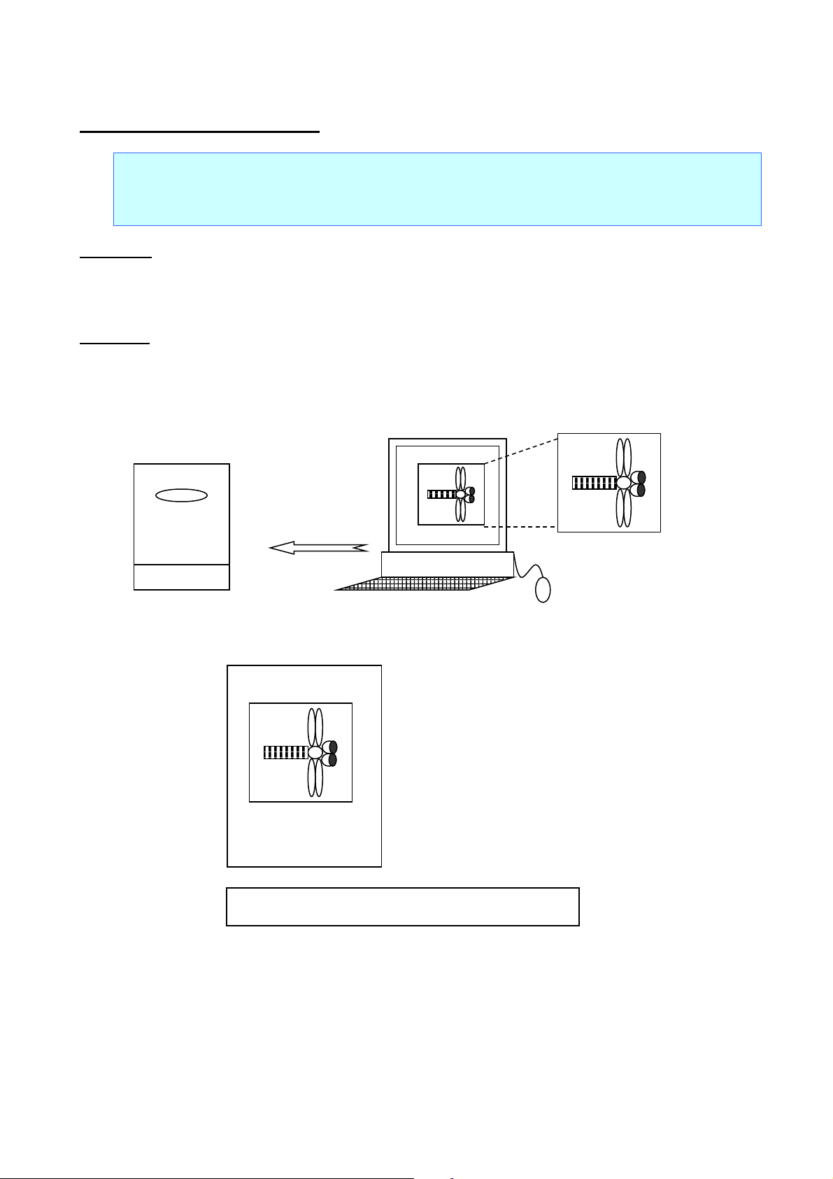
Image file
ESC i F Print transferred data
ASCII: ESC i F P n
Decim al: 27 105 70 80 n
Hexadecimal: 1B 69 46 50 n
Parameters
n: File header index
0≤n≤98
Description
Expands transferred data as image data in the print buffer.
Expands transferred image data from the print position.
Ignored if there is no image data.
ESC/P Command Reference
Must be
transferred in
advance
(.bmp)
This unit
Abcdefg
ABCDEFG
HIJK
Computer
Example: Combination of text and transferred image
- 70 -
5. Control Command Details
Page 76

3. Since the image does not
fit, it is pasted in after an
automatic line feed and
2. Enter transferred
3. Since the image does
2. Enter transferred
As with text, if the image data does not all fit in the current line, an error occurs.
ESC/P Command Reference
Abcdefg
1. Enter text.
Abcdefg Abcdefg
image.
Example: Image at a normal size
not fit, it is pasted in
after an automatic
line feed.
Abc
1. Enter text.
Abc Abc
image.
trimmed to fit between the
left and right margins.
Example: Image larger than distance between left and right margins
- 71 -
5. Control Command Details
Page 77
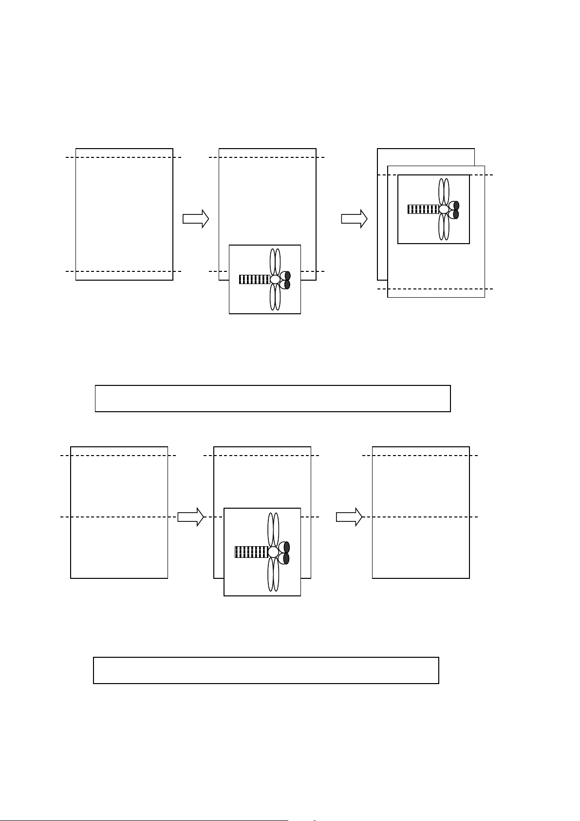
ESC/P Command Reference
2. Enter transferred
3. Since the image does
after an automatic
page feed.
2. Enter transferred
3. The entire image
If the result of pasting the transferred image exceeds the bottom margin position, the image is pasted in
after a page feed. However, if the transferred image is larger than the entire area between the top and
bottom margins, the entire image is ignored.
Abcdefg
WLMBGOr
Dabfdifpdzra
BGHJgmfg
gfdslrt
Abcdefg
WLMBGOr
Dabfdifpdzra
BGHJgmfg
gfdslrt
Abcdefg
1. Enter text.
image.
not fit, it is pasted in
Example: Image smaller than distance between top and bottom margins
Abcdefg
WLMBGOr
Dabfdifpdzra
1. Enter text.
Example: Image larger than distance between top and bottom margins
Abcdefg
WLMBGOr
Dabfdifpdzra
image.
Abcdefg
WLMBGOr
Dabfdifpdzra
is ignored.
- 72 -
5. Control Command Details
Page 78

ESC/P Command Reference
There are limits on the amount of image data that can be stored on the main unit. The storage capacity is
7MB. However, bitmap data is not stored as is, but is converted into the printer storage format by Transfer
Manager.
Image data larger than the media size is handled by deleting the portion of the image that does not fit within
the media. Even with the same image data, the portion that would be deleted differs depending on the
media orientation at the time.
- 73 -
5. Control Command Details
Page 79

ESC i a Switch command mode
ASCII: ESC i a n
Decim al: 27 105 97 n
Hexadecimal: 1B 69 61 n
Parameters
n: Command mode
0=ESC/P
1=Raster graphics
3=P-touch Template
Description
Sets the command mode to ESC/P, PTCBP (raster graphics) or P-touch Template.
Dynamically switches between the three modes.
ESC/P Command Reference
- 74 -
5. Control Command Details
Page 80

Number
Offset
Size
Name
Value/Reference
1 0 1
Print head mark
Fixed at 80h
2 1 1
Size
Fixed at 20h
3 2 1
Brother code
Fixed at “B” (42h)
4 3 1
Series code
Fixed at “0” (30h)
5 4 1
6 5 1
Country code
Fixed at “0” (30h)
7 6 1
Battery level information
Refer to table (11) below.
8 7 1
Extended error
Refer to table (10) below.
9 8 1
Error information 1
Refer to table (1) below.
10 9 1
Error information 2
Refer to table (2) below.
11
10
1
Media width
Refer to table (3) below.
12
11
1
Media type
Refer to table (4) below.
13
12
1
Number of colors
Fixed at 00h
14
13
1
Internal font information
Fixed at 00h
15
14
1
Internal Japanese font information
Fixed at 00h
16
15
1
Mode
Fixed at 00h
17
16
1
Density
Fixed at 00h
18
17
1
Media length
Refer to table (3) below.
19
18
1
Status type
Refer to table (5) below.
20
19
1
Phase type
Refer to table (6) below.
21
20
1
Phase number (higher order bytes)
Fixed at 00h
22
21
1
Phase number (lower order bytes)
Fixed at 00h
23
22
1
Notification number
Refer to table (7) below.
24
23
1
Expansion area (number of bytes)
Fixed at 00h
ESC i S Request printer status
ASCII: ESC i S
Decim al: 27 105 83
Hexadecimal: 1B 69 53
Parameters
None
Description
Requests the printer status.
The printer status consists of 32 bytes.
ESC/P Command Reference
Model code
“o” (6Fh) : P900W
“p” (70h) : P950NW
- 75 -
5. Control Command Details
Page 81

Number
Offset
Size
Name
Value/Reference
25
24
1
Media color information
Refer to table (8) below.
26
25
1
Ribbon color information
Refer to table (9) below.
27
26
6
Not used
Fixed at 00h
Flag
Mask
Definition
Bit 0
01h
Not used
Bit 1
02h
Not used
Bit 2
04h
“Cutter jam” error
Bit 3
08h
Low battery
Bit 4
10h
Not used
Bit 5
20h
Not used
Bit 6
40h
Not used
Bit 7
80h
Not used
Flag
Mask
Definition
Bit 0
01h
Not used
Bit 1
02h
Not used
Bit 2
04h
Not used
Bit 3
08h
Not used
Bit 4
10h
“Cover open” error
Bit 5
20h
High temperature error
Bit 6
40h
Feed error
Bit 7
80h
System error
(1) Error information 1
ESC/P Command Reference
(2) Error information 2
- 76 -
5. Control Command Details
Page 82

Media type
Media width
Media length
No tape
00h
00h
3.5-mm-wide tape
04h
00h
6-mm-wide tape
06h
00h
9-mm-wide tape
09h
00h
12-mm-wide tape
0Ch
00h
18-mm-wide tape
12h
00h
24-mm-wide tape
18h
00h
36-mm-wide tape
24h
00h
HS 5.8-mm-wide tape
06h
00h
HS 8.8-mm-wide tape
09h
00h
HS 11.7 -mm-wide tape
0Ch
00h
HS 17.7-mm-wide tape
12h
00h
HS 23.6-mm-wide tape
18h
00h
FLe 21mm x 45mm-wide tape
15h
2Dh
Media type
Value
No tape
00h
Laminated tape
01h
Non-laminated tape
03h
Fabric tape
04h
Heat-shrink Tube
11h
FLe tape
13h
Flexible ID tape
14h
Satin tape
15h
Incompatible tape
FFh
(3) Media width, Media length
ESC/P Command Reference
(4) Media type
- 77 -
5. Control Command Details
Page 83

Status type
Value
Reply to status request
00h
Not use
01h
Error occurred
02h
Not use
03 h
Not use
04h
Notification
05h
Phase change
06h
(Not used)
07h to 20h
Usage prohibited
21h to FFh
Phase type
Value
(Reception possible) Edit
00h
Printing
01h
ver opened while
(5) Status type
(6) Phase type, number
ESC/P Command Reference
Edit
Phase number (Dec) higher order bytes lower order bytes
(Reception possible)Edit 0 00h 00h
Feed 1 00h 01h
Printing
Phase number (Dec) higher order bytes lower order bytes
Printing 0 00h 00h
Not use 10 00h 0Ah
Co
20 00h 14h
receiving data
Not use 25 00h 19h
- 78 -
5. Control Command Details
Page 84

TZe-535(12mm)
(7) Notification number
(No notification) 00h
Cover open 01h
Cove r close 02h
Cooling started 03h
Cooling finished 04h
(8) Media color information
ESC/P Command Reference
Notification Value
Media color
Media color ID
White 01h
Other 02h
Clear 03h
Red 04h
Blue 05h
Yellow 06h
Green 07h
Black 08h
Clear 09h
Matte White 20h
Matte Clear 21h
Matte Silver 22h
Satin Gold 23h
Satin Silver 24h
Blue 30h
Remarks
TZe-545(18mm)
TZe-555(24mm)
Red 31h TZe-435(12mm)
Fluorescent Orange 40h
Fluorescent Yellow 41h
Berry Pink 50h TZe-MQP35
Light Gray 51h TZe-MQL35
Lime Green 52h TZe-MQG35
Yellow 60h
Pink 61h
Blue 62h
Heat-shrink Tube 70h
- 79 -
5. Control Command Details
Page 85

ESC/P Command Reference
Media color
Media color ID
White(Flex. ID) 90h
Yellow(Flex. ID) 91h
Clearning F0h
Stencil F1h
Incompatible FFh
(9) Ribbon color information
Ribbon color Ribbon color ID
White 01h
Red 04h
Blue 05h
Black 08h
Gold 0Ah
Blue 62h
Clearning F0h
Stencil F1h
Remarks
Other 02h
Incompatible FFh
(10) Extended error information
Error information Value
High resolution/High- speed printing error 1Dh
Power switching error 1Eh
Battery error 1Fh
Incompatible media error 21h
(11) Battery level information
Battery level Value
Full battery 00h
Half battery 01h
Low battery 02h
Changing required 03h
AC adapter in use 04h
Undetectable FFh
- 80 -
5. Control Command Details
Page 86

n=0 (or 30h):
Rotated printing is cancelled.
n=1 (or 31h):
Rotated printing is applied.
ESC i L Apply/cancel rotated printing
ASCII: ESC i L n
Decim al: 27 105 76 n
Hexadecimal: 1B 69 4C n
Parameters
n=0 and 1 or 48 and 49
Description
Applies rotated printing to the text.
ESC/P Command Reference
- 81 -
5. Control Command Details
Page 87

0:
Full cut
1:
Half cut
2:
Chain printing
3:
Special tape
4:
Not used
5:
Not used
6:
Not used
7:
Not used
ESC i C Specify cut setting
ASCII: ESC i C n
Decim al: 27 105 67 n
Hexadecimal: 1B 69 43 n
Parameters
0≤n≤255
Description
Specifies full cut, half cut, chain printing or special tape.
The n parameter (1 byte) specifies all settings in bit units, as shown below.
7 6 5 4 3 2 1 0
ESC/P Command Reference
If bit 0 of parameter n is “1”, full cut is specified. If it is “0”, full cut is cancelled.
If bit 1 of parameter n is “1”, half cut is specified. If it is “0”, half cut is cancelled.
If bit 2 of parameter n is “1”, chain printing is applied. If it is “0”, chain printing is cancelled.
If bit 3 of parameter n is “1”, special tape is specified. If it is “0”, special tape is cancelled.
When special tape is specified, full cut, half cut and chain printing are not available (same as being
cancelled).
- 82 -
5. Control Command Details
Page 88

n=0:
300 bps
n=1:
600 bps
n=2:
1200 bps
n=3:
2400 bps
n=4:
4800 bps
n=5:
9600 bps
n=6:
14400 bps
n=7:
19200 bps
n=8:
28800 bps
n=9:
31250 bps
n=10:
38400 bps
n=11:
57600 bps
n=12:
115200 bps
ESC i UB Specify baud rate
ASCII: ESC i U B n
Decim al: 27 105 85 66 n
Hexadecimal: 1B 69 55 42 n
Parameters
0≤n≤12
Description
As an RS-232C communication setting, the baud rate is specified as listed below.
ESC/P Command Reference
The setting is applied the next time that the machine is turned on.
- 83 -
5. Control Command Details
Page 89

n=0:
7 bit
n=1:
8 bit
n=0:
None
n=1:
ODD
n=2:
EVEN
ESC i Ub Specify bit length
ASCII: ESC i U b n
Decim al: 27 105 85 98 n
Hexadecimal: 1B 69 55 62 n
Parameters
0≤n≤1
Description
As an RS-232C communication setting, the bit length is specified as listed below.
The setting is applied the next time that the machine is turned on.
ESC/P Command Reference
ESC i UP Specify parity setting
ASCII: ESC i U P n
Decim al: 27 105 85 80 n
Hexadecimal: 1B 69 55 50 n
Parameters
0≤n≤2
Description
As an RS-232C communication setting, the parity is specified as listed below.
The setting is applied the next time that the machine is turned on.
- 84 -
5. Control Command Details
Page 90

n=0:
Hardware (DTR)
n=1:
X-ON/X-OFF
ESC i UC Specify busy control
ASCII: ESC i U C n
Decim al: 27 105 85 67 n
Hexadecimal: 1B 69 55 43 n
Parameters
0≤n≤1
Description
As an RS-232C communication setting, the busy control is specified as listed below.
The setting is applied the next time that the machine is turned on.
ESC/P Command Reference
- 85 -
5. Control Command Details
Page 91

n3=00h:
No margin
n3=01h:
Add margin (*Manufacturer’s default)
[1]
01h (Fixed)
[2]
00h (Fixed)
[3]
Setting
01h: Add margin
5.10 Advanced static commands
ESC iXE2 Specify barcode margin setting
ASCII: ESC i X E 2 n1 n2 n3
Decim al: 27 105 88 69 50 n1 n2 n3
Hexadecimal: 1B 69 58 45 32 n1 n2 n3
Parameters
n1: 01h (Fixed)
n2: 00h (Fixed)
00h≤n3≤01h
Description
Select an existence of barcode margin.
ESC/P Command Reference
This command is a static command.
Remarks
Invalid if n3 is a value outside of the allowable range
ESC iXE1 Retrieve barcode margin setting
ASCII: ESC i X E 1 n1 n2
Decim al: 27 105 88 69 49 n1 n2
Hexadecimal: 1B 69 58 45 31 n1 n2
Parameters
n1: 00h (Fixed)
n2: 00h (Fixed)
Description
Return a barcode margin setting as 3 Bytes data.
00h: No margin
The retrieved value is a value specified by a static command.
- 86 -
5. Control Command Details
Page 92

Raster printing (PCBP mode)
P-touch Template printing
Maximum print length
1 meter
Resolution (dpi)
360 dpi × 360 dpi
Bitmap fonts: 21 × 21, 28 × 28, 44 × 44, 56 × 56, 88 × 88, 120 ×
120 (dots)
Character style
None, Bold, Italics
Underline
Off, On
Character width
Half-width, Normal, Double-width
Horizontal
alignment
Rotate
Vertical, Horizontal
CODE39, ITF (I-2/5), EAN-13, EAN-8, UPC-A, UPC-E, CODABAR,
RSS-Limited, RSS Expanded (Standard, Stacked)
Width
Large, Medium, Small
115.2K, 57.6K, 38.4K, 31.25K, 28.8K, 19.2K, 14.4K, 9600, 4800,
2400, 1200, 600, 300
Busy
DTR, Xon/Xoff
Bit length
8, 7
Parity
NONE, ODD, EVEN
Stop bit
1 bit
Appendix A: Specifications
BROTHER PT-P900W/P950NW ESC/P specifications
ESC/P Command Reference
Printing method
Te xt
Printing
Bar-
code
ESC/P printing
Font Bitmap fonts: Helsinki, Letter Gothic
Size (dots)
Left, Center, Right, Justify
CODE128, GS1-128 (UCC/EAN-128), QR Code (Model 1, Model 2,
Protocols
micro QR), PDF417 (Standard, Truncate, Micro PDF417),
DataMatrix (ECC200 Square, ECC200 Rectangular), MaxiCode,
RSS-14 (Standard, Truncated, Stacked, Stacked Omni),
Baud rate (bps)
RS
Transmission
Settings that appear in bold and underlined are the default settings.
- 87 -
Appendix A: Specifications
Page 93
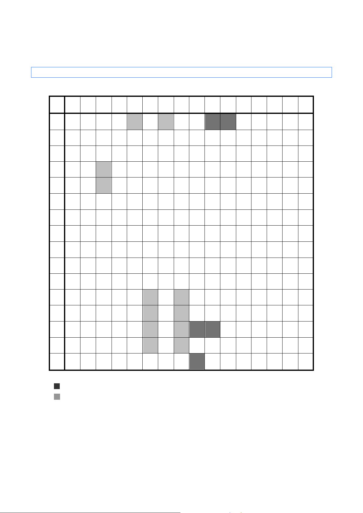
Appendix B: Character Code Tab le s
Character code tables
(1) Windows1252 (Western Europe)
0 1 2 3 4 5 6 7 8 9 A B C D E F
0 SP 0 @ P ` p € ° À Ð à ð
1 ! 1 A Q a q ~ ‘ ¡ ± Á Ñ á ñ
2 ” 2 B R b r , ’ ¢ ² Â Ò â ò
3 # 3 C S c s ƒ “ £ ³ Ã Ó ã ó
4 $ 4 D T d t „ ” ¤ ´ Ä Ô ä ô
ESC/P Command Reference
5 % 5 E U e u … • ¥ µ Å Õ å õ
6 & 6 F V f v † – | ¶ Æ Ö æ ö
7 ’ 7 G W g w ‡ — § · Ç × ç ÷
8 ( 8 H X h x ^ ˜ ¨ ¸ È Ø è ø
9
A
B
C
D
E
F
Note
)
9 I Y i y ‰
* : J Z j z Š š ª º Ê Ú ê ú
+ ; K [ k { < > « » Ë Û ë û
, < L \ l
- = M ] m } - ½ Í Ý í ý
. > N ^ n ~ Ž ž ® ¾ Î Þ î þ
/ ? 0 _ o
DEL
Œ œ ¬ ¼ Ì Ü ì ü
¦
Ÿ ¯ ¿ Ï ß ï ÿ
© ¹ É Ù é ù
* "
" indicates that a space is printed.
* "
" indicates that the character will change if the international character set is switched.
- 88 Appendix B: Character Code Tables
Page 94
(2) Windows1250 (Eastern Europe)
0 1 2 3 4 5 6 7 8 9 A B C D E F
0 SP 0 @ P ` p € tˇ ° Ŕ Đ ŕ đ
1 ! 1 A Q a q À ‘ ˇ ± Á Ń á ń
2 " 2 B R b r , ’ ˘ ˛ Â Ň â ň
3 # 3 C S c s Ľ “ Ł ł Ă Ó ă ó
4 $ 4 D T d t „ ” ¤ ´ Ä Ô ä ô
5 % 5 E U e u … • Ą µ Ĺ Ő ĺ ő
6 & 6 F V f v † – | ¶ Ć Ö ć ö
7 ’ 7 G W g w ‡ — § · Ç × ç ÷
ESC/P Command Reference
8 ( 8 H X h x ľ ¨ ¸ Č Ř č ř
9
A
B
C
D
E
F
Note
* "
" indicates that a space is printed.
* "
" indicates that the character will switch when the international character set is changed.
)
9 I Y i y ‰ ™ © ą É Ů é ů
* : J Z j z Š š Ş ş Ę Ú ę ú
+ ; K [ k { < > « » Ë Ű ë ű
, < L \ l
– = M ] m } Ť ť – ˝ Í Ý í ý
. > N ^ n ~ Ž ž ® ľ Î Ţ î ţ
/ ? O _ o
DEL
Ś ś ¬ Ľ Ě Ü ě ü
¦
Ź ź Ż ż Ď ß ď ˙
- 89 Appendix B: Character Code Tables
Page 95
(3) Brother standard
0 1 2 3 4 5 6 7 8 9 A B C D E F
0 SP 0 @ P ` p Ç É á ░ └ α
1 ! 1 A Q a q ü æ í ▒ ┴ ß ±
2 ” 2 B R b r é Æ ó ▓ ┬
3 # 3 C S c s â ô ú │ ├ ¾
4 $ 4 D T d t ä ö ñ ┤ ─
5 % 5 E U e u à ò Ñ ┼ §
ESC/P Command Reference
6 & 6 F V f v å û
7 ’ 7 G W g w ç ù
a
µ
¯
o
¯
8 ( 8 H X h x ê ÿ ¿ © ╚ °
9
A
B
C
D
E
F
Note
)
9 I Y i y ë Ö ® ╣ ╔ ┘ ·
* : J Z j z è Ü € ║ ╩ ┌ Ω
+ ; K [ k { ï ¢ ½ ╗ ╦ δ
, < L \ l
- = M ] m } ì ¥ ¡ TEL ═ ø ²
. > N ^ n ~ Ä Pts «
/ ? 0 _ o
DEL
î £ ¼ ╝ ╠
¦
FAX
╬
Å ƒ » ┐
÷
³
* "
" indicates that a space is printed.
* "
" indicates that the character will change if the international character set is switched.
- 90 Appendix B: Character Code Tables
Page 96

ESC/P Command Reference
0
United States
# $ @ [ \ ] ^ ` { ¦ } ~ 1
France
# $ à ° ç § ^ ` é ù è ¨ 2
Germany
# $ § Ä Ö Ü ^ ` ä ö ü ß 3
Britain
£ $ @ [ \ ] ^ ` { ¦ } ~ 4
Denmark I
# $ @ Æ Ø Å ^ ` æ ø å ~ 5
Sweden
# ¤ É Ä Ö Å Ü é ä ö å
ü
7
Spain I
Pt $ @ ¡ Ñ ¿ ^ ` ¨ ñ }
~
9
Norway
# ¤ É Æ Ø Å Ü é æ ø å ü 10
Denmark II
# $ É Æ Ø Å Ü é æ ø å ü 11
Spain II
# $ á ¡ Ñ ¿ é ` í ñ ó ú 12
Latin America
# $ á ¡ Ñ ¿ é ü í ñ ó ú 13
Korea
# $ @
[ W ] ^ ` { ¦ } ~
International character set table
Corresponding characters that switch in each language when the international character set is changed
n
23 24 40 5B 5C 5D 5E 60 7B 7C 7D 7E
6 Italy # $ @ ° \ é ^ ù à ò è ì
8 Japan # $ @ [ ¥ ] ^ ` { ¦ } ~
64 Legal # $ § ° ´ " ¶ ` © ® † TM
- 91 Appendix B: Character Code Tables
Page 97

ESC/P Command Reference
Appendix C: Introducing the Brother Developer Center
Useful information for developers, such as applications, tools, SDKs as well as FAQs, are provided in the
Brother Developer Center.
http://www.brother.com/product/dev/index.htm
- 92 -
Appendix C: Introducing the Brother Developer Center
Page 98

 Loading...