

Page 1

Software Developer's Manual
Raster Command Reference
PT-H500/P700/E500
Version 1.10
Page 2

The Brother logo is a registered trademark of Brother Industries, Ltd.
Brother is a registered trademark of Brother Industries, Ltd.
© 2014 Brother Industries, Ltd. All rights reserved.
Microsoft and Windows are registered trademarks of Microsoft Corporation in the United States and other
countries.
Each owner whose software title is mentioned in this document has a Software License Agreement specific to
its proprietary programs.
Any trade names and product names of companies appearing on Brother products, related documents and
any other materials are all trademarks or registered trademarks of those respective companies.
Page 3

IMPORTANT - PLEASE READ CAREFULLY
Note
This documentation (“Documentation”) provides information that will assist you in controlling your Printer
PT-XXXX (where “XXXX” is the model name).
You may use the Documentation only if you first agree to the following conditions.
If you do not agree to the following conditions, you may not use the Documentation.
Condition of Use
You may use and reproduce the Documentation to the extent necessary for your own use of your Printer
Model (“Purpose”). Unless expressly permitted in the Documentation, you may not;
(i) copy or reproduce the Documentation for any purpose other than the Purpose,
(ii) modify, translate or adapt the Documentation, and/or redistribute it to any third party,
(iii) rent or lease the Documentation to any third party, or,
(iv) remove or alter any copyright notices or proprietary rights legends included within the Documentation.
No Warranty
a. Any updates, upgrades or alteration of the Documentation or Printer Model will be performed at the sole
discretion of Brother. Brother may not respond to any request or inquiry about the Documentation.
b. THIS DOCUMENTATION IS PROVIDED TO YOU "AS IS" WITHOUT WARRANTY OF ANY KIND,
WHETHER EXPRESS OR IMPLIED, INCLUDING, BUT NOT LIMITED TO, THE IMPLIED WARRANTY
OF FITNESS FOR A PARTICULAR PURPOSE. BROTHER DOES NOT REPRESENT OR WARRANT
THAT THIS DOCUMENTATION IS FREE FROM ERRORS OR DEFECTS.
c. IN NO EVENT SHALL BROTHER BE LIABLE FOR ANY DIRECT, INDIRECT, PUNITIVE, INCIDENTAL,
SPECIAL OR CONSEQUENTIAL DAMAGES OR ANY DAMAGES WHATSOEVER, ARISING OUT OF
THE USE, INABILITY TO USE, OR THE RESULTS OF USE OF THE DOCUMENTATION OR ANY
SOFTWARE PROGRAM OR APPLICATION YOU DEVELOPED IN ACCORDANCE WITH THE
DOCUMENTATION.
Page 4

Raster Command Reference
Contents
Introduction ······························································································ 1
About Raster Commands ············································································ 2
1. Printing Using Raster Commands ································ ····························· 3
2. Print Data ······························································································ 5
2.1 Print data overview ························································································ 5
2.2 Sample (analyzing the print data of the test page) ················································ 7
2.2.1 Preparation ........................................................................................................... 7
2.2.2 Checking the print data ......................................................................................... 7
2.2.3 Explanation of print data for the test page .......................................................... 10
2.3 Page data details·························································································· 13
2.3.1 Resolution .......................................................................................................... 13
2.3.2 Page size ............................................................................................................ 14
2.3.3 Feed amount ...................................................................................................... 17
2.3.4 Maximum and minimum lengths ......................................................................... 18
2.3.5 Raster line .......................................................................................................... 19
3. Print Command List ··············································································· 22
4. Printing Command Details ······································································ 23
NULL Invalidate ................................................................................................... 23
ESC @ Initialize ...................................................................................................... 23
ESC i S Status information request ......................................................................... 23
ESC i a Switch dynamic command mode ............................................................... 31
ESC i z Print information command ........................................................................ 32
ESC i M Various mode settings ............................................................................... 33
ESC i K Advanced mode settings ........................................................................ 33
ESC i d Specify margin amount (feed amount) ....................................................... 34
M Select compression mode ......................................................................... 35
g Raster graphics transfer ............................................................................ 37
Z Zero raster graphics ................................................................................... 37
FF Print command........................................................................................... 37
Control-Z Print command with feeding ...................................................................... 38
5. Flow Charts··························································································· 39
5.1 Concurrent printing normal flow for USB connection ············································ 40
5.2 Concurrent printing error flow for USB connection (when feeding at the end of the page)41
5.3 Concurrent printing error flow for USB connection (with a concurrent printing error such
as end of tape) ·································································································· 42
5.6 Buffered printing normal flow for USB connection ················································ 43
5.7 Buffered printing error flow for USB connection ··················································· 44
5.8 Buffered printing cooling flow for USB connection ··············································· 45
Appendix A: USB Specifications ································································· 46
Appendix B: Introducing the Brother Developer Center ·································· 47
- i -
Page 5

Raster Command Reference
Introduction
This material provides the necessary information for directly controlling the Brother printer PT-XXXX (where
“XXXX” is the model name).
This information is provided assuming that the user has full understanding of the operating system being used
and basic mastery of USB in a developer's environment.
Details concerning the USB interface are not described in this material. If a USB interface is being used, refer
to “Appendix A: USB Specifications” to prepare the interface.
Read the model names that appear in the screens in this manual as the name of your printer.
- 1 Introduction
Page 6

Raster Command Reference
About Raster Commands
Using raster commands an PT-XXXX printer (where “XXXX” is the model name) can be used to print without
using our printer driver.
This operation is useful in the following situations.
When printing from an operating system other than Windows
(Example: When printing from a Linux computer or mobile terminal)
When adding print functions to an existing system
In addition, printing can be performed with advanced settings.
In this material, “raster” refers to binary bitmap data (collection of dots).
Refer to this material to print by sending initialization commands and control codes together with raster data to
the PT-XXXX printer (hereafter, referred to as “printer”).
This manual describes the procedure for adding these codes and sending the data.
- 2 About Raster Commands
Page 7
Raster Command Reference
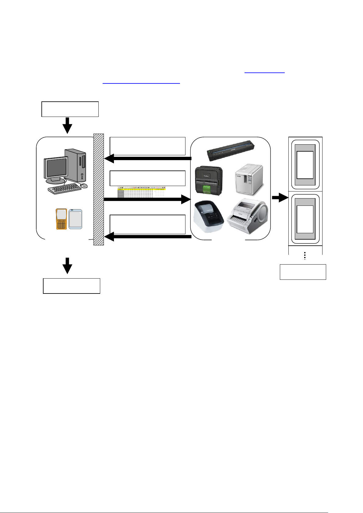
(2) Send the status
(Confirm the printer status.)
(1) Open the port
(5) Send the status
(Confirm that printing is completed.)
(6) Close the port
Port
(4) Print
At your side
(3) Send the print data
Your printer
Computer, mobile
terminal, etc.
1. Printing Using Raster Commands
The printing procedure is described below. For detailed flow charts, refer to “5. Flow Charts”. For details on
each command, refer to “4. Printing Command Details”.
- 3 -
1. Printing Using Raster Commands
Page 8

Raster Command Reference
(1) Open the USB port
Open the USB port in the operating environment. The procedure for opening the USB port is not described
in this material.
(2) Confirm the printer status sent from the printer
The “status information request” command is sent to the printer, the status information received from the
printer is analyzed, and then the status of the printer is determined.
For details on the “status information request” command and on the definitions of “status”, refer to “Status
information request” in “4. Printing Command Details”.
(3) Send the print data
If the status analysis confirms that media compatible with the print data is loaded into the printer and that
no error has occurred, the print data is sent.
The structure of the print data is explained in the next section, “2. Print Data”.
Note:
No command can be sent to the printer after the print data is transmitted and until the completion
of printing is confirmed.
Even the “status information request” command cannot be sent during printing.
(4) Print the data
(5) Confirm that printing is completed
When printing is completed, the status is received from the printer.
If this status is analyzed to confirm that printing is completed, printing one page is considered finished.
If the print job has multiple pages, (2) through (4) are repeated.
(6) Close the USB port
After all printing is finished, close the USB port.
Note:
In order to print at high speed when a USB port is used to send uncompressed raster data, the
Brother PT-XXXX starts printing when it starts to receive print data, instead of waiting for a print
command (concurrent printing).
For the processing flow, for example when managing errors, refer to “5. Flow Charts”.
- 4 -
1. Printing Using Raster Commands
Page 9

Raster Command Reference
Sequence
Command Name
Description/Example
1
Invalidate
Sends a 100-byte invalidate command, and then resets the printer
to the receiving state.
2
Initialize
Initializes for printing.
1Bh, 40h (Fixed)
Sequence
Command Name
Description/Example
1
Switch dynamic
command mode
Switches the printer to raster mode.
1Bh, 69h, 61h, 01h
2
Print information
command
Sets the print information for the printer.
When printing 100 mm on 24-mm-wide tape with the 180 dpi
model:
1Bh, 69h, 7Ah, 84h, 00h, 18h, 00h, 9Ch, 02h, 00h, 00h, 00h, 00h
3
Various mode
settings
When auto cut is enabled:
1Bh, 69h, 4Dh, 40h
4
Advanced mode
settings
When chain printing is disabled:
1BH,69H,4B,08H
5
Specify margin
amount
Specifies the amount of the margins.
For 2 mm margins on the 180 dpi model:
1Bh, 69h, 64h, 0Eh, 00h
6
Select compression
mode
Selects the compression mode for raster graphics.
To send the data compressed to TIFF format:
4Dh, 02h
2. Print Data
2.1 Print data overview
The print data is constructed of the following: (1) initialization commands, (2) control codes, (3) raster data,
and (4) print commands. If the print job consists of multiple pages, (2) through (4) are repeated.
(1) Initialization commands
Specified only once at the beginning of the job.
(2) Control codes
Added at the beginning of each page and sent for each page.
- 5 -
2. Print Data
Page 10

Sequence
Command Name
Description/Example
-
Raster graphics
transfer
Sends a raster line that contains data with pixels set to “ON”.
-
Zero raster graphics
Sends a raster line with all pixels set to “0”.(Valid only when TIFF
is selected as the compression mode)
5Ah (Fixed)
Sequence
Command Name
Description/Example
-
Print command
Specifies at the end of a page that is not the last page.
0Ch(Fixed)
-
Print command with
feeding
Specifies at the end of the last page.
1Ah (Fixed)
(3) Raster data
Repeated for each page in the print job.
(4) Print commands
Specified at the end of the page.
Raster Command Reference
- 6 -
2. Print Data
Page 11
Raster Command Reference
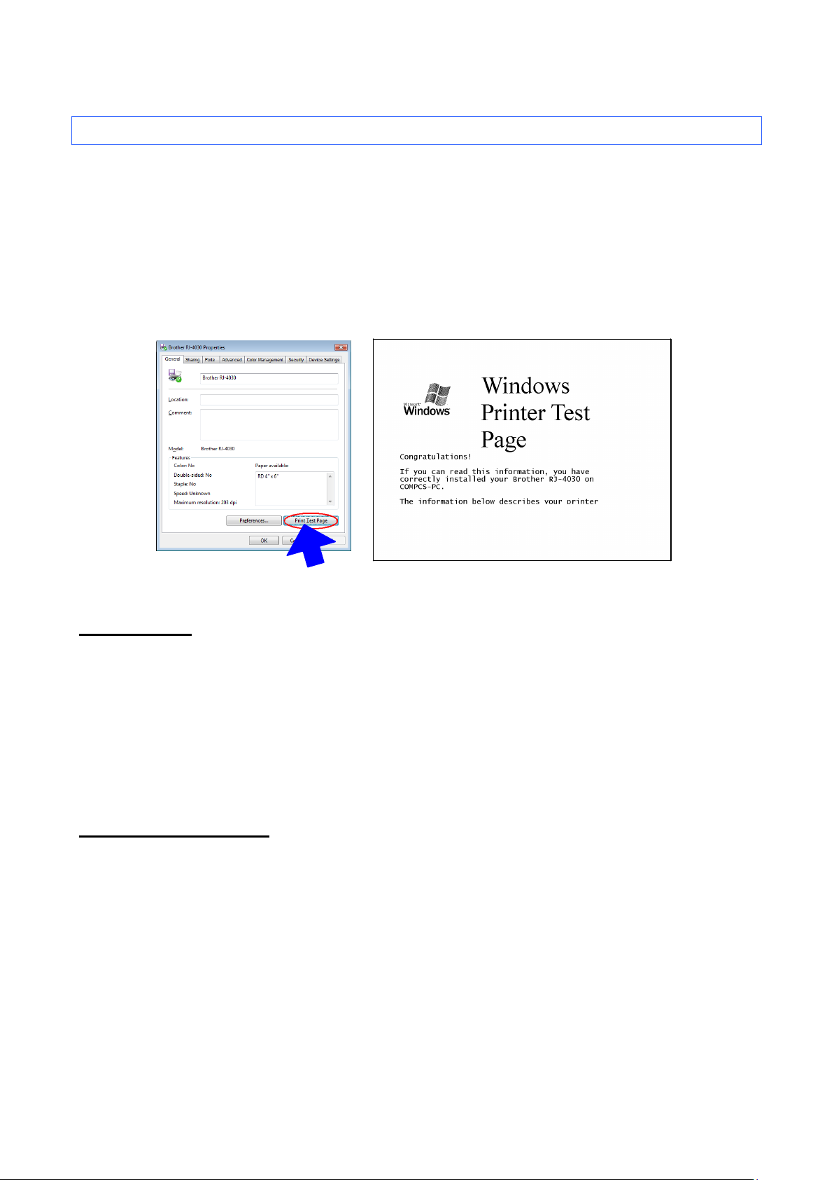
Test page
Printer Properties
2.2 Sample (analyzing the print data of the test page)
The print data created by the printer driver is described here.
As an example, we will check the print data created when the [Print Test Page] button in the printer
Properties dialog box is clicked to print the test page.
Since the print data differs depending on the print settings of the printer, refer to this procedure and try
creating print data with various print settings.
Furthermore, this procedure is for the Windows® 7 operating environment. A similar procedure can be
performed if you are using a different operating system.
2.2.1 Preparation
Install the two listed below.
・ Printer driver of the Brother PT-XXXX
・ Binary file editor
The data that we will analyze in this sample is a binary file.
Therefore, use a binary file editor to display and check the contents of the binary file.
2.2.2 Checking the print data
The procedure for checking the print data is provided below.
Step 1: Change the port of the printer to “FILE:”.
Step 2: Print the desired item (in this case, the test page), and then specify the file name.
Step 3: Open the created file in the binary file editor to check it.
- 7 -
2. Print Data
Page 12
Raster Command Reference
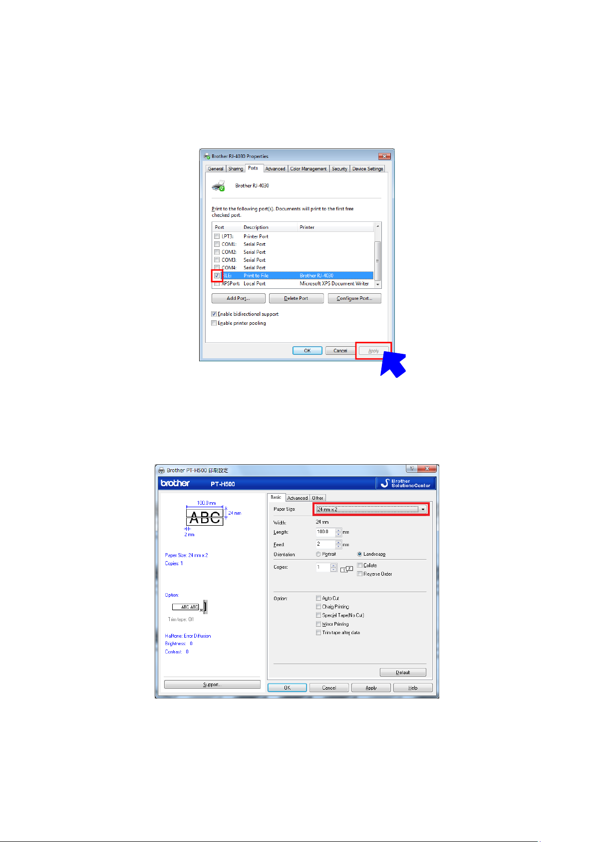
Step 1: Change the port of the printer to “FILE:”.
Open the Printers and Faxes folder, and then right-click the printer (in this case, RJ-4030) to display
the Properties dialog box. In the Properties dialog box, click the [Ports] tab, select the “FILE:” check
box, and then click the [Apply] button.
[Ports] tab of the printer Properties dialog box
Step 2: Print the item (in this case, the test page), and then specify the file name.
Print the test page with “24mm x 2” selected as the paper size in the print settings.
- 8 -
2. Print Data
Page 13
Raster Command Reference
(1) Initialization
commands
(2) Control codes
(4) Print commands
(3) Raster data
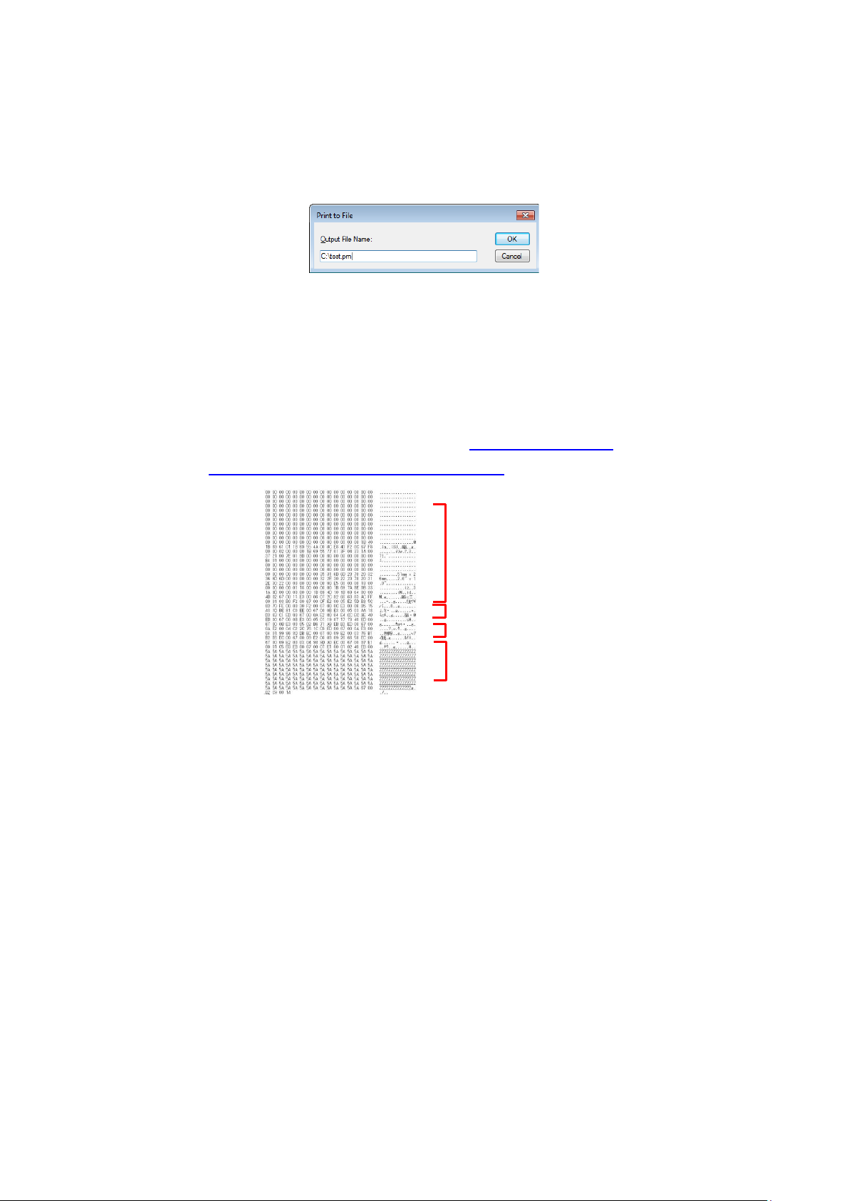
When the test page is printed with the printer, a dialog box appears so that the file name can be
specified. (Refer to the illustration below.)
After a file name is typed in and the [OK] button is clicked, the printer driver creates the print data and
saves it in a file with the specified name.
Dialog box for specifying the file name
Step 3: Open the print data in the binary file editor.
Open the saved file in the binary file editor. The rows of numbers that appear are the print data. (Refer
to the illustration below.)
The print data is constructed of the following: (1) initialization commands, (2) control codes, (3) raster
data and (4) print commands, which were described in “2.1 Print data overview”. For details on the print
data, refer to “2.2.3 Explanation of print data for the test page”.
Print data
- 9 -
2. Print Data
Page 14
Raster Command Reference
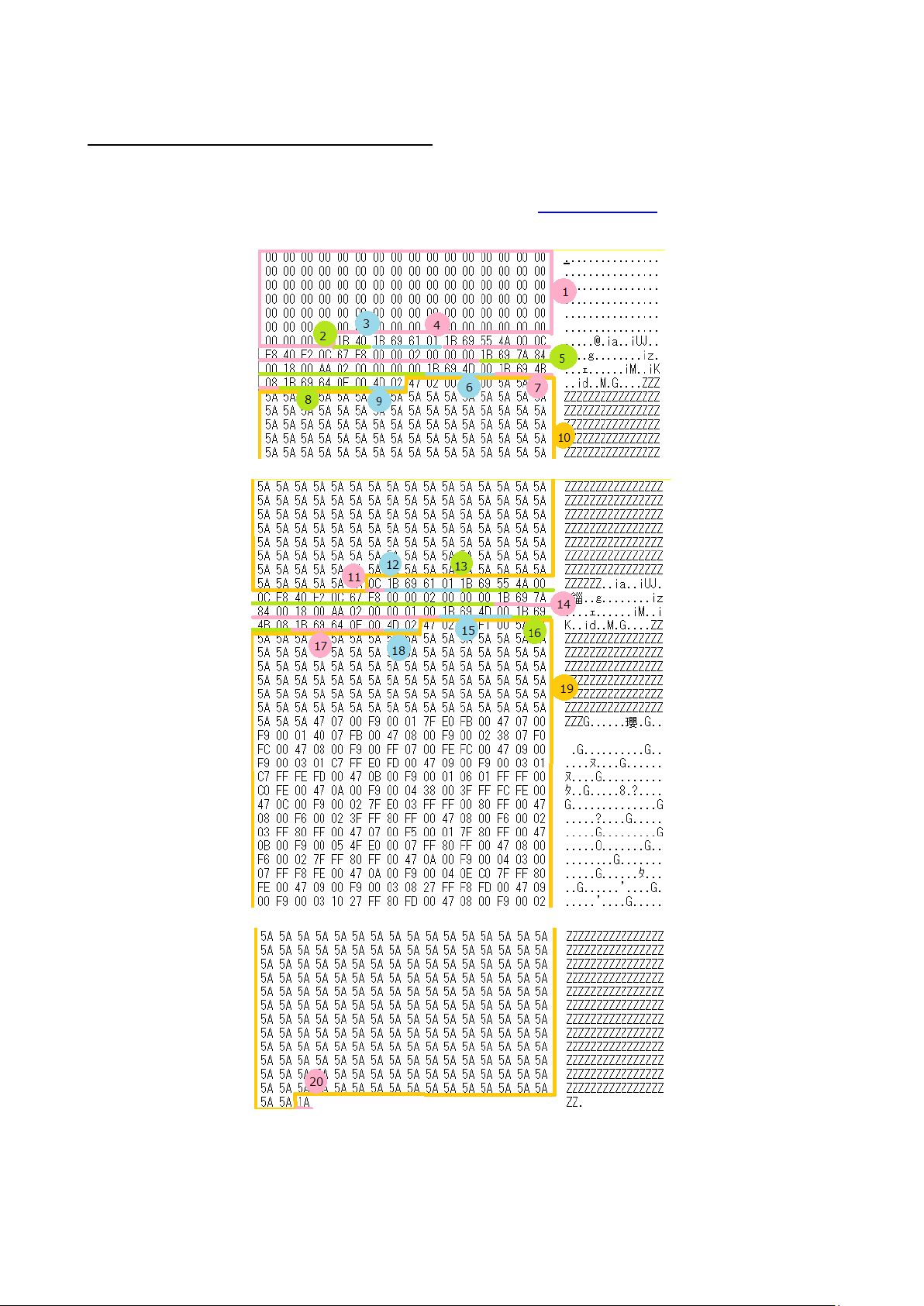
2.2.3 Explanation of print data for the test page
The print data for the test page outputted in the previous section is described below.
The following illustration shows the print data created in section “2.2.1 Preparation” opened in the binary file
editor.
Print data
- 10 -
2. Print Data
Page 15

Raster Command Reference
No.
Command Name
Description
1
Invalidate
A 100-byte invalidate command is sent.
2
Initialize
The “initialize” command is sent.
3
Switch dynamic
command mode
The printer is switched to raster mode.
Send this command before sending raster data to the printer.
4
Job ID setting
commands
Internal specification commands
Since this is a command for outputting with the commercial
version driver, it is unnecessary for the user to send this
command.
5
Print information
command
Media size information for the print data is sent.
This is the command for “24 mm” tape.
6
Various mode settings
(1Bh+69h+4Dh+00H)
This is a command for specifying a mode.
Here, nothing is specified.
7
Advanced mode
settings
This is the command for specifying settings for the advanced
mode.
In this case, “no chain printing” is enabled.
8
Specify margin amount
Specifies the amount of the margins.
This is the command for “15 dots”.
9
Select compression
mode
TIFF compression mode is selected.
10
Raster data
Raster data continues.
11
Print command
Since it is not the last page, the print command is sent at the end
of the page.
12
Switch dynamic
command mode
The printer is switched to raster mode.
Send this command before sending raster data to the printer.
13
Job ID setting
commands
Internal specification commands
Since this is a command for outputting with the commercial
version driver, it is unnecessary for the user to send this
command.
14
Print information
command
Media size information for the print data is sent.
This is the command for “24 mm” tape.
15
Various mode settings
(1Bh+69h+4Dh+00H)
This is a command for specifying a mode.
Here, nothing is specified.
16
Advanced mode
settings
This is the command for specifying settings for the advanced
mode.
In this case, “no chain printing” is enabled.
17
Specify margin amount
Specifies the amount of the margins.
This is the command for “15 dots”.
18
Select compression
TIFF compression mode is selected.
Descriptions for the numbers in the print data on the previous page are provided in the following table.
For details on each command, refer to “4. Printing Command Details”.
- 11 -
2. Print Data
Page 16

Raster Command Reference
mode
19
Raster data
Raster data continues.
20
Print command with
feeding
Since it is the last page, the print command with feeding is sent at
the end of the page.
- 12 -
2. Print Data
Page 17

Resolution
Height-to-Width Proportion
180 dpi high, 180 dpi wide
1:1
2.3 Page data details
2.3.1 Resolution
PT-H500/P700/E500
Raster Command Reference
- 13 -
2. Print Data
Page 18

Feeding direction
6
5
Landscape
3
1 4 2
Print area
ID
Tape Size
Designation
1 2 3 4 5
6
263
3.5 mm
3.5 mm
0.13"
3.40 mm
24 dots
→2.3.4
3.40 mm
24 dots
→2.3.4
0.00 mm
0 dots
→2.3.3
257
6 mm
6 mm
0.23"
5.90 mm
42 dots
→2.3.4
4.50 mm
32 dots
→2.3.4
0.70 mm
5 dots
→2.3.3
258
9 mm
9 mm
0.35”
9.00mm
64 dots
→2.3.4
7.10 mm
50 dots
→2.3.4
0.98 mm
7 dots
→2.3.3
259
12 mm
12 mm
0.47”
11.9mm
84 dots
→2.3.4
9.90 mm
70 dots
→2.3.4
0.98 mm
7 dots
→2.3.3
260
18 mm
18 mm
0.70”
18.1 mm
128 dots
→2.3.4
15.8 mm
112 dots
→2.3.4
1.12 mm
8 dots
→2.3.3
261
24 mm
24 mm
0.94”
24.0 mm
170 dots
→2.3.4
18.1 mm
128 dots
→2.3.4
2.96 mm
21 dots
→2.3.3
2.3.2 Page size
(a) Continuous length tape
Raster Command Reference
Number 1 Width 2 Length
3 Print area width (maximum printing width) 4 Print area length
5 Width offset 6 Length offset
TZe tape
- 14 -
2. Print Data
Page 19

ID
Tape Size
Designation
1 2 3 4 5
6
415
6 mm
HS 5.8mm
HS 0.23"
5.60 mm
40 dots
→2.3.4
3.90 mm
28 dots
→2.3.4
0.80 mm
6 dots
→2.3.3
416
9 mm
HS 8.8mm
0.34”
8.70mm
62 dots
→2.3.4
6.80 mm
48 dots
→2.3.4
1.10 mm
8 dots
→2.3.3
417
12 mm
HS 11.7mm
0.46”
11.6mm
82 dots
→2.3.4
9.30 mm
66 dots
→2.3.4
1.10 mm
8 dots
→2.3.3
418
18 mm
HS 17.7mm
0.69”
17.8 mm
126 dots
→2.3.4
14.9 mm
106 dots
→2.3.4
1.40 mm
10 dots
→2.3.3
419
24 mm
HS 23.6mm
HS 0.93”
23.7 mm
168 dots
→2.3.4
18.1 mm
128 dots
→2.3.4
2.80 mm
20 dots
→2.3.3
Heat-Shrink Tube
Raster Command Reference
- 15 -
2. Print Data
Page 20

ID
Tape Size
Designation
1 3 5
7
[3]×Split number+[5]
×2
8
[3]×Split
number
279 12 mm
12 mm×2
0.47”×2
11.9 mm
84 dots
9.90 mm
70 dots
0.98 mm
7 dots
9.90mmx2+0.98mmx2
70dotsx2+7dotsx2
9.90mmx2
70dotsx2
285
12 mm
12 mm×3
0.47”×3
11.9 mm
84 dots
9.90 mm
70 dots
0.98 mm
7 dots
9.90mmx3+0.98mmx2
70dotsx3+7dotsx2
9.90mmx3
70dotsx3
291
12 mm
12 mm×4
0.47”×4
11.9 mm
84 dots
9.90 mm
70 dots
0.98 mm
7 dots
9.90mmx4+0.98mmx2
70dotsx4+7dotsx2
9.90mmx4
70dotsx4
280 18 mm
18 mmx2
0.70”x2
18.1 mm
128 dots
15.8 mm
112 dots
1.12 mm
8 dots
15.8mmx2+1.12mmx2
112dotsx2+8dotsx2
15.8mmx2
112dotsx2
286 18 mm
18 mmx3
0.70”x3
18.1 mm
128 dots
15.8 mm
112 dots
1.12 mm
8 dots
15.8mmx3+1.12mmx2
112dotsx3+8dotsx2
15.8mmx3
112dotsx3
292
18 mm
18 mmx4
0.70”x4
18.1 mm
128 dots
15.8 mm
112 dots
1.12 mm
8 dots
15.8mmx4+1.12mmx2
112dotsx4+8dotsx2
15.8mmx4
112dotsx4
281 24mm
24mmx2
0.94”x2
24.0 mm
170 dots
18.1 mm
128 dots
2.96 mm
21 dots
18.1mmx2+2.96mmx2
128dotsx2+21dotsx2
18.1mmx2
128dotsx
287 24mm
24mmx3
0.94”x3
24.0 mm
170 dots
18.1 mm
128 dots
2.96 mm
21 dots
18.1mmx3+2.96mmx2
128dotsx3+21dotsx2
18.1mmx3
128dotsx3
293
24mm
24mmx4
0.94”x4
24.0 mm
170 dots
18.1 mm
128 dots
2.96 mm
21 dots
18.1mmx4+2.96mmx2
128dotsx4+21dotsx2
18.1mmx4
128dotsx4
Raster Command Reference
(b) Split size
Number 1 Width 2 Length
3 Print area width (maximum printing width) 4 Print area length
5 Width offset 6 Length offset
7Overall width 8 Width of overall print area
TZe tape
- 16 -
2. Print Data
Page 21

Type
Minimum margin
setting
Maximum margin
setting
Minimum margin
setting with no
precut
(Unrelated to
driver)
Normal
2mm
0.08"
14 dots
127 mm
5"
900 dots
24.3mm
0.96”
172dots
2.3.3 Feed amount
The feed amount (left and right margins) is defined below.
180dpi×180dpi
Raster Command Reference
- 17 -
2. Print Data
Page 22

Type
Minimum length
Maximum length
Normal
4.4mm
0.18”
31 dots
1000 mm
39.37”
7086dots
Type
Minimum length
Maximum length
Normal
4.4 mm
0.18”
31 dots
500 mm
19.69”
3543dots
2.3.4 Maximum and minimum lengths
The maximum and minimum lengths are defined below.
180dpi×180dpi
TZe tape
Heat-Shrink Tube
Raster Command Reference
* The minimum length with the driver (minimum print data length: 2 mm margins × 2 + minimum print
area) is based on the machine specifications (due to the machine cutter position), and the minimum
length of tape that can be fed out is 24.5 mm.
For example, even when the minimum print data of 4.4 mm is created, the print result will be the 24.5
mm of tape shown below, since the minimum length of tape that can be fed out is 24.5 mm.
In other words, the print data will be on 24.5 mm of tape when the print data length is 24.5 mm or less.
- 18 -
2. Print Data
Page 23

Raster Command Reference
Feeding direction
Print area
Rasterized
Feeding direction
Print area
Print head
Expansion direction
RasterLine 3
RasterLine 2
RasterLine 1
Zero Raster 1
Zero Raster 1
RasterLine 4
MSB LSB
1stB
MSB LSB
MSB LSB
MSB LSB
2ndB
3rdB
4thB ...
2.3.5 Raster line
As shown below, the parts with data to be printed are converted with “raster graphics transfer”, and the
parts with no data are converted with “zero raster graphics”. On the actual tape, margins (feed) are
added specified with “various mode settings” at the beginning and the end.
The following shows the relationship between the raster graphics parameters and the pixels.
- 19 -
2. Print Data
Page 24

0 pin
First byte
Left and right margins
Last byte
Raster line
Feeding direction
Print area
Pins on print head
Number of
print area
pins
Number of pins
for right margin
Total number
of pins
Number of pins
for left margin
Tape Type
Number of pins
for left margin
Number of print area
pins
Number of pins
for right
margin
Number of bytes for raster
graphics transfer
3.5 mm
52
24
52
16
6 mm
48
32
48
16
9 mm
39
50
39
16
12 mm
29
70
29
16
18 mm 8 112 8 16
24 mm 0 128 0 16
Total number of pins: PT-H500/P700/E500 128pin
Raster Command Reference
TZe tape:
- 20 -
2. Print Data
Page 25

Tape Type
Number of pins
for left margin
Number of print area
pins
Number of pins
for right margin
Number of bytes for raster
graphics transfer
6 mm
50
28
50
16
9 mm
40
48
40
16
12 mm
31
66
31
16
18 mm
11
106
11
16
24 mm 0 128 0 16
Heat-Shrink Tube:
Raster Command Reference
- 21 -
2. Print Data
Page 26

ASCII Code
Binary Code
Description
NULL
00
Invalidate
ESC @
1B 40
Initialize
ESC i S
1B 69 53
Status information request
ESC i a
1B 69 61
Switch dynamic command mode
ESC i z
1B 69 7A
Print information command
ESC i M
1B 69 4D
Various mode settings
ESC i K
1B 69 4B
Advanced mode settings
ESC i d
1B 69 64
Specify margin amount (feed amount)
M
4D
Select compression mode
g
67
Raster graphics transfer
Z
5A
Zero raster graphics
FF
0C
Print command
Control-Z
1A
Print command with feeding
3. Print Command List
Raster Command Reference
- 22 -
3. Print Command List
Page 27

Raster Command Reference
4. Printing Command Details
NULL Invalidate
ASCII: NULL
Hexadecimal: 00
Description
Skipped
If data transmission is to be stopped midway, send the “initialize” command after sending the “invalidate”
command for the appropriate number of bytes to return to the receiving state, where the print buffer is
cleared.
ESC @ Initialize
ASCII: ESC @
Hexadecimal: 1B 40
Description
Initializes mode settings.
Also used to cancel printing.
ESC i S Status information request
ASCII: ESC i S
Hexadecimal: 1B 69 53
Description
Send a request to the printer for status information. For details on the status, refer to the previous section.
The size is fixed at 32 bytes.
Note
Before sending print data to the printer, this command should be sent once. Since error
information is automatically sent by the printer during printing, do not send this command while
printing.
For details on transmission of the status, refer to “5. Flow Charts”.
- 23 -
4. Printing Command Details
Page 28

Raster Command Reference
Number
Offset
Size
Name
Value/Reference
1 0 1
Print head mark
Fixed at 80h
2 1 1
Size
Fixed at 20h
3 2 1
Brother code
Fixed at “B” (42h)
4 3 1
Series code
Fixed at “0” (30h)
5 4 1
Model code
PT-H500: Fixed at “d” (64h)
PT-E500: Fixed at “e” (65h)
PT-P700: Fixed at “g” (67h)
6 5 1
Country code
Fixed at “0” (30h)
7 6 1
Reserved
Fixed at “00h”
8 7 1
Reserved
Fixed at 00h
9 8 1
Error information 1
Refer to table (1) below.
10 9 1
Error information 2
Refer to table (2) below.
11
10
1
Media width
Refer to table (3) below.
12
11
1
Media type
Refer to table (4) below.
13
12
1
Number of colors
Fixed at 00h
14
13
1
Fonts
Fixed at 00h
15
14
1
Japanese fonts
Fixed at 00h
16
15
1
Mode
Value specified where the “various
mode settings” command
00h if not specified
17
16
1
Density
Fixed at 00h
18
17
1
Media length
Refer to table (3) below.
19
18
1
Status type
Refer to table (5) below.
20
19
1
Phase type
Refer to table (6) below.
21
20
1
Phase number
(higher order bytes)
22
21
1
Phase number
(lower order bytes)
23
22
1
Notification number
Refer to table (7) below.
24
23
1
Expansion area (number of
bytes)
Fixed at 00h
25
24
1
Tape color information
Refer to table (8) below.
26
25
1
Text color information
Refer to table (9) below.
27
26
4
Hardware settings
Sets the default hardware information
to be used for checking
- 24 -
4. Printing Command Details
Page 29

Raster Command Reference
31
30
1
Reserved
Fixed at 00h
32
31
1
Reserved
Fixed at 00h
- 25 -
4. Printing Command Details
Page 30

Flag
Mask
Definition
Bit 0
01h
“No media” error
Bit 1
02h
(Not used)
Bit 2
04h
Cutter jam
Bit 3
08h
Weak batteries
Bit 4
10h
(Not used)
Bit 5
20h
(Not used)
Bit 6
40h
High-voltage adapter
Bit 7
80h
(Not used)
Flag
Mask
Definition
Bit 0
01h
“Replace media” error (with a serial connecting)
Wrong media
Bit 1
02h
(Not used)
Bit 2
04h
(Not used)
Bit 3
08h
(Not used)
Bit 4
10h
“Cover open” error
Bit 5
20h
Overheating error
Bit 6
40h
(Not used)
Bit 7
80h
(Not used)
(1) Error information 1
Raster Command Reference
(2) Error information 2
- 26 -
4. Printing Command Details
Page 31

Media
Media Width
Media Length
No tape 0 0
3.5 mm 4 0
6 mm 6 0
9 mm 9 0
12 mm
12
0
18 mm
18
0
24 mm
24
0
Media Type
Value
No media
00h
Laminated tape
01h
Non-laminated tape
03h
Heat-Shrink Tube
11h
Incompatible tape
FFh
(3) Media width and length
The media width and length is described in millimeters. 0~255 (0 to FFh)
(a) TZe tape
* Media Width: The tape width is indicated in millimeters.
* Media Length: Fixed at 00h
Raster Command Reference
(4) Media type
- 27 -
4. Printing Command Details
Page 32

Status Type
Value
Reply to status request
00h
Printing completed
01h
Error occurred
02h
Exit IF mode
03h (not used)
Turned off
04h
Notification
05h
Phase change
06h
(Not used)
07h to 20h
(Reserved)
21h to FFh
Phase State
Phase Type
Editing state (reception possible)
00h
Printing state
01h
Phase
Value (Dec.)
Higher Order Bytes
Lower Order Bytes
Editing state (reception
possible)
0
00h
00h
Feed
1
00h
01h
Phase
Value (Dec.)
Higher Order Bytes
Lower Order Bytes
Printing
0
00h
00h
(Not used)
10
00h
0Ah
Cover open while
receiving
20
00h
14h
(Not used)
25
00h
19h
(5) Status type
If an error occurred during printing, the printer returns the error status.
Raster Command Reference
(6) Phase type and phase number
If the phase number is not used, both are fixed at 00h.
Editing state
Printing state
- 28 -
4. Printing Command Details
Page 33

Notification
Value
Not available
00h
Cover open
01h
Cover closed
02h
Tape color
Tape color ID
Notes
White
01h
Other
02h Clear
03h Red
04h Blue
05h Yellow
06h Green
07h Black
08h
Clear(White text)
09h
Matte White
20h Matte Clear
21h
Matte Silver
22h Satin Gold
23h Satin Silver
24h
Blue(D)
30h
TZe-535(12mm)
TZe-545(18mm)
TZe-555(24mm)
Red(D)
31h
TZe-435(12mm)
Fluorescent Orange
40h
Fluorescent Yellow
41h
Berry Pink(S)
50h
TZe-MQP35
Light Gray(S)
51h
TZe-MQL35
Lime Green(S)
52h
TZe-MQG35
Yellow(F)
60h Pink(F)
61h Blue(F)
62h
White(Heat-shrink Tube)
70h
White(Flex. ID)
90h
(7) Notification number
(8)Tape color information
Raster Command Reference
- 29 -
4. Printing Command Details
Page 34

Yellow(Flex. ID)
91h Clearning
F0h Stencil
F1h
Incompatible
FFh
Text color
Text color ID
White
01h
Red
04h
Blue
05h
Black
08h
Gold
0Ah
Blue(F)
62h
Clearning
F0h
Stencil
F1h
Other
02h
Incompatible
FFh
(10)Text color information
Raster Command Reference
- 30 -
4. Printing Command Details
Page 35

Raster Command Reference
ESC i a Switch dynamic command mode
ASCII: ESC i a {n1}
Hexadecimal: 1B 69 61 {n1}
Parameters
Definitions of {n}:
0: ESC/P mode (default)
1: Raster mode (Be sure to switch to this mode.)
3: P-touch Template mode
Description Dynamically switches between the printer's command modes. A printer that receives this command
operates in the specified command mode until the printer is turned off.
The printer must be switched to raster mode before raster data is sent to it. Therefore, send this command
to switch the printer to raster mode.
- 31 -
4. Printing Command Details
Page 36

Raster Command Reference
{n1}:
Valid flag; Specifies which values are valid
#define PI_KIND 0x02 // Media type
#define PI_WIDTH 0x04 // Media width
#define PI_LENGTH 0x08 // Media length
#define PI_QUALITY 0x40 // Priority given to print quality(Not used)
#define PI_RECOVER 0x80 // Printer recovery always on
{n2}:
Media type
No tape: 00h
Laminated tape: 01h
Non-laminated tape:03h
Heat-Shrink Tube:11h
Incompatible tape:FFh
{n3}:
{n3}: Media width (mm)
{n4}: Media length (mm)
For the media of width 24 mm, specify as n3=18h and n4=00h.
n4 is normally 00h, regardless of the paper length.
{n4}:
{n5-n8}:
Raster number = n8*256*256*256 + n7*256*256 + n6*256 + n5
If the media is not correctly loaded into the printer when the valid flag for PI_KIND,
PI_WIDTH and PI_LENGTH are set to “ON”, an error status is returned (Bit 0 of “(2)
Error information 2” is set to “ON”.)
{n9}:
Starting page: 0
Other pages: 1
{n10}:
Fixed at 0
ESC i z Print information command
ASCII: ESC i z {n1} {n2} {n3} {n4} {n5} {n6} {n7} {n8} {n9} {n10}
Hexadecimal: 1B 69 7A {n1} {n2} {n3} {n4} {n5} {n6} {n7} {n8} {n9} {n10}
Description
Specifies the print information.
Definitions of {n1} through {n10}
- 32 -
4. Printing Command Details
Page 37

ESC i M Various mode settings
ASCII: ESC i M {n1}
Hexadecimal: 1B 69 4D {n1}
Parameters
Definitions of {n1}
The meaning of each bit in a 1-byte parameter is described below.
0 ~ 5bit:Not used
6bit:Auto cut 1. Automatically cuts 0. Does not automatically cut
7bit:Mirror printing 1. Mirror printing 0. No mirror printing
ESC i K Advanced mode settings
Raster Command Reference
ASCII: ESC i K {n1}
Hexadecimal: 1B 69 4B {n1}
Parameters
Definitions of {n1}
The meaning of each bit in a 1-byte parameter is described below.
0 ~ 2bit:Not used
3bit:No chain printing
When printing multiple copies, the labels are fed after the last one is printed.
1.No chain printing(Feeding and cutting are performed after the last one is printed.)
0:Chain printing(Feeding and cutting are not performed after the last one is printed.)
4bit:Special tape (no cutting)
Labels are not cut when special tape is installed.
1.Special tape (no cutting) ON 0:Special tape (no cutting) OFF
5 ~ 6bit:Not used
7bit:No buffer clearing when printing
The expansion buffer of the machine is not cleared with the “no buffer clearing when printing”
command.
If this command is sent when the data of the first label is printed (it is specified between the
“initialize” command and the print data), printing is possible only if a print command is sent with the second
or later label.
1.No buffer clearing when printing ON 0.No buffer clearing when printing OFF
- 33 -
4. Printing Command Details
Page 38

Print area
Margin amount
Tape
Paper
Cut line
ESC i d Specify margin amount (feed amount)
ASCII: ESC i d {n1} {n2}
Hexadecimal: 1B 69 64 {n1} {n2}
Description
Specifies the amount of the margins.
Margin amount (dots)=n1+n2*256
(a) Continuous length tape
Raster Command Reference
- 34 -
4. Printing Command Details
Page 39

Raster Command Reference
0
No-compression mode (Enabled)
1
Reserved (Disabled)
2
TIFF (Enabled)
Without compression:
00 00 00 00 00 00 00 00 00 00 00 00 00 00 00
00 00 00 00 00 22 22 23 BA BF A2 22 2B……
With compression:
ED 00 FF 22 05 23 BA BF A2 22 2B …
a b c
a.
Since “00h” is repeated for 20 bytes, 20d -> 19d -> 13h changed into a negative number is EDh.
Therefore: ED 00
b.
Since “22h” is repeated for 2 bytes, 2d -> 1d -> 1h changed into a negative number is FFh.
Therefore: FF 22
c.
The following 6 bytes remain unchanged. 6d -> 5d -> 5h
Therefore: 05 23 BA BF A2 22 2B
Continue for the remaining number of bytes for the uncompressed data. Even if 00h continues until the
end, it cannot be omitted.
M Select compression mode
ASCII: M {n}
Hexadecimal: 4D {n}
Parameters
Definitions of {n}
Description Selects the compression mode. Data compression is available only for data in raster graphic transfer.
[TIFF(Pack Bits)]
1-byte units
If the same data is repeated, the number of data units and that 1 byte of data are specified.
If different data is in a series, the number of data items and all of the different data are specified.
If the same data is repeated, the number of data units is specified as the actual number minus 1,
expressed as a negative number.
If different data is in a series, the number of data units is specified as the number of bytes minus 1,
expressed as a positive number.
If the above process results in more than 16 bytes (PT-H500/P700/E500) of compressed data, the data
is treated as being all different. As a result, the data will be 17 bytes (PT-H500/P700/E500) , including the
1 byte that specifies the data length.
Example
1 raster of raster graphics transfer:
- 35 -
4. Printing Command Details
Page 40

Raster Command Reference
0 pin
Last byte
First byte
Tape margin
Raster line with
compression
Feeding direction
Print area
Pins on print head
Number of
print area
pins
Number
of offset
pins
Total
number
of pins
Number
of unused
pins
Raster line with
no compression
Explanation of “TIFF compression mode”
With compression, the data for the “raster graphics transfer” command is based on 16 bytes
(PT-H500/P700/E500) of the total number of pins (PT-H500/P700/E500: 128). As shown below, with no
compression, the sum of the number of offset pins and the number of pins within the print area is the byte data.
However, with compression, the number of unused pins is also added to the data. In other words, with
compression, this becomes 16 bytes when it is expanded by the printer, regardless of the tape width.
- 36 -
4. Printing Command Details
Page 41

Raster Command Reference
g Raster graphics transfer
ASCII: g {n1} {n2} {d1} ... {dk}
Hexadecimal: 67 {n1} {n2} {d1} ... {dk}
Description
Transfers the specified number of bytes (k) of data.
The data is expanded by overwriting from the position where the margin was added.
If the expanded data does not reach the end of the expansion buffer, the remainder is filled with 0 data.
If the expanded data exceeds the end of the expansion buffer, the excess is cut off.
Parameters
{n1}{n2} Specified number of bytes k = n1 + n2*256
0000h ≦ Specified number of bytes k ≦ First positive number that exceeds the value
of the number of print head pins divided by 8 (Gauss number)
{n} Number of bytes of raster data (d1 to dk)
However, use the following value if no compression is specified as the compression mode.
PT-H500/P700/E500:n=16
{d1~dn} Raster data.
Z Zero raster graphics
ASCII: Z
Hexadecimal: 5A
Description Fills raster line with 0 data.
FF Print command
ASCII: FF
Hexadecimal: 0C
Description Used as a print command at the end of pages other than the last page when multiple pages are printed.
- 37 -
4. Printing Command Details
Page 42

Control-Z Print command with feeding
ASCII: Control-Z
Hexadecimal: 1A
Description Used as a print command at the end of the last page.
Raster Command Reference
- 38 -
4. Printing Command Details
Page 43

Raster Command Reference
5. Flow Charts
Normally, printing is performed as buffered printing.
However, if the printer is connected via USB and uncompressed data is received, concurrent printing is
performed.
Note:
Concurrent printing:Printing starts immediately after the printer receives print data.
Buffered printing:Printing starts after one page of print data is received.
- 39 -
5. Flow Charts
Page 44

Raster Command Reference
Computer (host)
Printer
Status information request
Status (response to status information request)
Printing
Display ing printing
Printing of the 1st
page is actually not
finished, but the
“Printing
completed” status
and “Waiting to
receive” phase are
sent.
Sending control codes
Sending raster data
Initialize
The printer is
initialized.
Status
(Phase change:
“Printing”)
Sending a print command (print command with feeding (1A)
for the last page or print command (0C) for other pages)
Phase change
“Printing” received.
“Printing completed”
received.
Sending raster data
Sending raster data
Sending raster data
Status (“Printing completed”)
Status (Phase change:
“Waiting to receive”)
Sending control code/raster data
Sending raster data
Sending raster data
Finishing process for
printing page 1
Sending data for page 2
Printing 1st page
Printing 2nd page
Sending raster data
READ
The status of the
printer (media, etc.)
is checked and a
response is sent.
If there are no
problems with the
printer status (media,
etc.), the data is
transmitted. If there
is a problem, an error
appears.
Displaying sending
READ
Data received.
Beginning printing
without waiting for
a print command
Status
(Phase change:
“Printing”)
Invalidate
The printer is
reset.
5.1 Concurrent printing normal flow for USB connection
- 40 -
5. Flow Charts
Page 45

Raster Command Reference
Computer (host)
Status information request
Status (response to status information request)
The status of the
printer (media, etc.)
is checked and a
response is sent.
Data received.
Beginning printing
without waiting for a
print command
Printing
Displaying printing
Displaying sending
Sending control codes
Sending raster data
Initialize
The printer is
initialized.
Status
(Phase change:
“Printing”)
Sending a print command (print command with feeding (1A)
for the last page or print command (0C) for other page)
“Printing completed”
received.
Sending raster data
Status (Phase change: “Waiting to receive”)
Sending control code/raster data
Status
(“Error occurred”)
Sending raster data
Sending raster data
Sending a print command (print command with feeding (1A)
for the last page or print command (0C) for other pages)
“Error Occured” received.
Initialize
If there are no
problems with the
printer status (media,
etc.), the data is
transmitted. If there is
a problem, an error
appears.
Printing of the 1st
page is actually not
finished, but the
“Printing completed”
status and “Waiting
to receive” phase are
sent.
An error appears.
When restarted, data is
resent starting with the
1st page since “Printing”
for the 2nd page is not
received.
If an error occurs, all
data read from the
computer is cleared.
Reprinting 1st page
READ
READ
READ
Printer
Phase change
“Printing” received.
Status (“Printing completed”)
Finishing process
for printing page 1
Sending data for page 2
Error occurred
Resending process
for data of 1st page
Displaying printing
Displaying printing
Invalidate
The printer is
reset.
5.2 Concurrent printing error flow for USB connection (when feeding at the end of the page)
- 41 -
5. Flow Charts
Page 46

Raster Command Reference
Computer (host)
If there are no
problems with the
printer status (media,
etc.), the data is
transmitted. If there is
a problem, an error
appears.
The status of the printer
(media, etc.) is checked
and a response is sent.
Data received.
Beginning printing
without waiting for a
print command
Printing
Printing of the 1st page
is actually not finished,
but the “Printing
completed” status and
“Waiting to receive”
phase are sent.
Finishing process for
printing page 1
Sending data for page 2
The printer is initialized.
Sending a print command (print command with feeding (1A)
for the last page or print command (0C) for other pages)
If an error occurs, all
data read from the
computer is cleared.
Displaying printing
Sending a print command (print command with feeding (1A)
for the last page or print command (0C) for other pages)
Reprinting 2nd page
An error appears.
When restarted, data is resent
starting with the 2nd page
since “Printing” for the 2nd
page is received.
READ
READ
Any jobs with errors
remaining in the printer
are cleared.
Status information request
Status (response to status information request)
Sending control codes
Sending raster data
Initialize
Status
(Phase change :
“Printing”)
Sending raster data
Status (“Printing completed”)
Status (Phase change: “Waiting to receive”)
Sending control code/raster data
Sending raster data
Sending raster data
Status
(Phase change :
“Printing”)
Phase change
“Printing” received.
“Printing completed” received.
Phase change
“Waiting to receive” received.
Initialize
Status
(“Error Occurred”)
Phase change
“Printing” received.
“Error Occured” received.
Printer
Printing 1st page
Printing 2nd page
Error occurred
Resending process for
data of 2nd page
READ
Displaying sending
Displaying printing
Invalidate
5.3 Concurrent printing error flow for USB connection (with a concurrent printing error such as end of tape)
- 42 -
5. Flow Charts
Page 47

Raster Command Reference
If there are no
problems with the
printer status (media,
etc.), the data is
transmitted. If there is
a problem, an error
appears.
Data received.
Printing
Displaying printing
Displaying sending
Finishing process for
printing 1st page
Sending data for
2nd page
The printer is
initialized.
Phase change
“Printing” received.
“Printing completed”
received.
Phase change
“Waiting to receive” received.
Printing 1st page
Printing 2nd page
Status information request
Status (response to status information request)
Sending control codes
Sending raster data
Initialize
Sending raster data
Sending raster data
Sending raster data
Sending a print command (print command with feeding (1A)
for the last page or print command (0C) for other page)
Status
(“Printing completed”)
Status
(Phase change: “Waiting to receive”)
Sending control codes
Sending raster data
Printer
Computer (host)
The status of the
printer (media, etc.)
is checked and a
response is sent.
Sending raster data
READ
READ
Status
(Phase change: “Printing”)
Invalidate
The printer is
reset.
5.6 Buffered printing normal flow for USB connection
- 43 -
5. Flow Charts
Page 48

Computer (host)
Status information request
Data received.
Printing
Displaying printing
Displaying sending
Sending control codes
Sending raster data
Initialize
The printer is
Initialized.
Sending a print command (print command with feeding (1A)
for the last page or print command (0C) for other page)
Phase change
“Printing” received.
Status (“Error Occurred”)
READ
Printer
If there are no
problems with the
printer status
(media, etc.), the
data is transmitted.
If there is a problem,
an error appears.
READ
Status (response to status information
request) or an error is displayed
Status
(Phase change: “Printing”)
Error occurred
The status of the
printer (media, etc.)
is checked and a
response is sent.
Invalidate
The printer is reset.
5.7 Buffered printing error flow for USB connection
Raster Command Reference
- 44 -
5. Flow Charts
Page 49

Raster Command Reference
Status (response
to status request)
Data received.
Printing
Displaying printing
Displaying sending
The printer is
initialized.
Phase change
“Printing” received.
Phase change “Waiting
to receive” received.
Printing 1st page
Printing 2nd page
Status
(Notification: “Cooling (started)”)
Printing
Cooling
* “Cooling (standard)”
and “Cooling (finished)”
may be repeated
multiple times during
one printing operation.
Computer (host)
Status information request
Sending control codes
Sending raster data
Initialize
Sending a print command (print command with feeding (1A)
for the last page or print command (0C) for other page)
Status
(Printing completed)
Status
(Phase change: “Waiting to receive”)
Sending control codes
Status
(Phase change :“Printing”)
“Printing completed”
received.
Status
(Notification: “Cooling (finished)”)
Sending raster data
Printer
Sending raster data
If there are no
problems with the
printer status
(media, etc.), the
data is transmitted.
If there is a problem,
an error appears.
READ
Status (response to status
information request)
READ
End process for
printing 1st page
Sending data for 2nd
page
The printer is
reset.
Invalidate
5.8 Buffered printing cooling flow for USB connection
- 45 -
5. Flow Charts
Page 50

Item
Description
Vendor ID
0x04F9
Product ID
PT-H500 : 0x205E
PT-E500: 0x205F
PT-P700 : 0x2061
Class
Printer(PT-H500/PT -P700/PT-E500)
Character string for
manufacturer
Character string descriptor: 0x01
0x0409: “Brother”
Character string for
serial number
Character string descriptor: 0x03
0x0409: “000000001”
Last nine digits of the printer’s serial number
Device speed
Full speed
Number of interfaces
1 (No alternate interfaces)
With the printer class
Power supply
Self-powered (As a printer class, Bus power is also set to “ON”.)
End point 1
In bulk (Sends the status from the printer to the computer.)
Maximum packet size: 64 bytes
End point 2
Out bulk (Sends print commands and data from the computer to the printer.)
Maximum packet size: 64 bytes
Appendix A: USB Specifications
USB specifications 1.1
Raster Command Reference
- 46 Appendix A: USB Specifications
Page 51

Raster Command Reference
Appendix B: Introducing the Brother Developer Center
Useful information for developers, such as applications, tools, SDKs as well as FAQs, are provided in the
Brother Developer Center.
http://www.brother.com/product/dev/index.htm
- 47 -
Appendix B: Introducing the Brother Developer Center
Page 52

 Loading...