

Brother PT-9200PC Service Manual

SERVICE MANUAL
MODEL: PT-9200PC

SERVICE MANUAL
MODEL: PT-9200PC

Copyright Brother 1998
All rights reserved.
No part of this publication may be reproduced in any
form or by any means without permission in writing from
the publisher.
Specifications are subject to change without notice.

PREFACE
This publication is a service manual covering the specifications, theory of operation,
disassembly/
reassembly procedure, and troubleshooting of the Brother label printer PT-9200PC. It is
intended for service personnel and other concerned persons to accurately and quickly provide
after-sale service for our PT-9200PC.
To perform appropriate maintenance so that the machine is always in best condition for the
customer, the service personnel must adequately understand and apply this manual.
This manual is made up of four chapters and an appendix.
CHAPTER I SPECIFICATIONS
CHAPTER II MECHANISMS
CHAPTER III ELECTRONICS
CHAPTER IV TROUBLESHOOTING
APPENDIX CIRCUIT DIAGRAM

CHAPTER I
SPECIFICATIONS

CONTENTS
CHAPTER I SPECIFICATIONS
1.1MECHANICAL SPECIFICATIONS................................................................................................I-1
1.1.1 External View..................................................................................................................I-1
1.1.2 Input Specifications.........................................................................................................I-2
1.1.3 Display Specifications......................................................................................................I-2
1.1.4 Printing Specifications.....................................................................................................I-2
1.1.5 Tape Cassette Specifications..........................................................................................I-3
1.1.6 Tape Cutter Specifications...............................................................................................I-3
1.1.7 PC Interface Specifications.............................................................................................I-3
1.2ELECTRONIC SPECIFICATIONS.................................................................................................I-4
1.2.1 Power Supply Specifications............................................................................................I-4
1.1 MECHANICAL SPECIFICATIONS
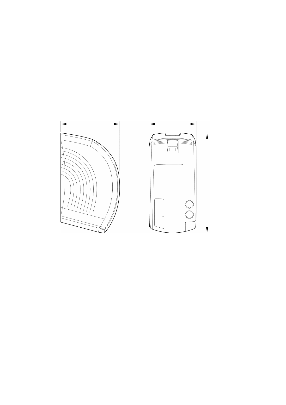
1.1.1 External View
(1) Dimensions (W × D × H) 115 mm × 245 mm × 145 mm
(2) Weight
Machine proper Approx. 1.5 kgf (only the machine)
Machine and package Approx. 2.4 kgf
145 mm 115 mm
245 mm
Fig. 1.1-1 External View
I - 1
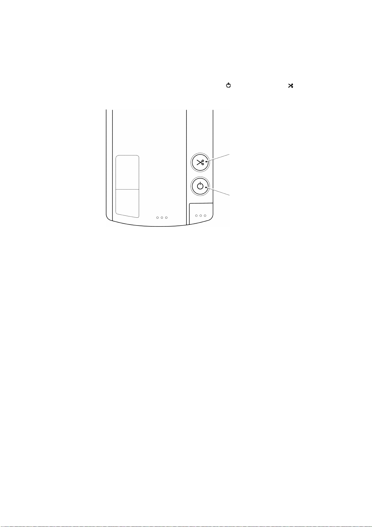
1.1.2 Input Specifications
(1) Number of keys 2 (ON/OFF ( ) and FEED/CUT ( ) keys)
(2) Key layout See Fig. 1.1-2.
FEED/CUT key
ON/OFF key
Fig. 1.1-2 Key Layout
1.1.3 Display Specifications
(1) Display method LED (green/red)
1.1.4 Printing Specifications
(1) Printing method Thermal transfer or heat sensitizing method
(2) Printing speed 20 mm/sec
(3) Print head
Type Thin film thermal head
Dimensions of a heating
element 0.08 mm wide by 0.0545 mm high
by thermal head
Printing on plastic tapes (laminated and nonlaminated tapes) or special tapes (instant
lettering tape, non-laminated thermal film
tape, and fabric printing tape)
(Fixed print head and tape feed mechanism)
384 dots × 1 dot
I - 2

1.1.5 Tape Cassette Specifications
(1) Cassette Cartridge type
(2) Types of cassettes
Laminated tape cassette Laminated tape, ink ribbon, and adhesive
Non-laminated tape
cassette Non-laminated tape and ink ribbon
Instant lettering tape
cassette Instant lettering tape and ink ribbon
Fabric printing tape
cassette Fabric printing tape and ink ribbon
Stamp tape cassette Porous-stamp tape and mount
(3) Tape size
Laminated tape 6,9,12,18,24,36 mm 8 m
Non-laminated tape 6,9,12,18,24 mm 8 m
Instant lettering tape 18 mm 8 m
Fabric printing tape 18 mm 8 m
Stamp tape 18 mm 8 m
base tape
Width Length
(5 m for fluorescent
coating tapes)
1.1.6 Tape Cutter Specifications
(1) Tape cutting method Automatic full cutting method
1.1.7 PC Interface Specifications
(1) Method
Serial (RS-232C)
Baud rate Max. 115.2 K
(2) Attachments
I/F cable Dedicated cable
Editor Dedicated editor
(not user-replaceable)
Automatic half cutting method
(not user-replaceable)
I - 3

1.2 ELECTRONIC SPECIFICATIONS
1.2.1 Power Supply Specifications
(1) Power supply method
Commercially available power (120V AC, 60 Hz for North America, and 230V
AC, 50 Hz for Europe) is input and stabilized to generate DC voltage by the
switching regulator in the machine.
The power supply cord is inserted into an inlet.
I - 4

CHAPTER II
MECHANISMS

CONTENTS PT99007
CHAPTER II MECHANISMS
2.1THEORY OF MECHANISM OPERATION....................................................................................II-1
2.1.1 Printing Mechanism........................................................................................................II-1
2.1.2 Roller Holder Assy Setting and Retracting Mechanism....................................................II-3
2.1.3 Regular Tape and Ribbon Feed Mechanism...................................................................II-4
2.1.4 Tape Automatic Full Cutter Mechanism..........................................................................II-6
2.1.5 Tape Automatic Half Cutter Mechanism..........................................................................II-7
2.1.6 Forced Tape Eject Mechanism.......................................................................................II-8
2.1.7 Cover Open Button (Cover Lock Button).........................................................................II-9
2.1.8 Cover Open (Cover Lock) Sensor...................................................................................II-9
2.2DISASSEMBLY AND REASSEMBLY.........................................................................................II-10
2.2.1 Disassembly Procedures..............................................................................................II-11
[1] Removing the Tape Cassette.................................................................................II-11
[2] Removing the Cassette Cover................................................................................II-11
[3] Disassembly of the Cassette Cover Components...................................................II-12
[4] Removing the Lower Cover....................................................................................II-13
[5] Removing the Bottom Cover and the Front Cover...................................................II-14
[6] Removing the Power Supply PCB Assy..................................................................II-16
[7] Removing the Main PCB Assy and the Mechanical Printing Unit.............................II-18
[8] Disassembly of the Body Cover..............................................................................II-20
[9] Removing the Eject Unit Assy, the Half Cutter Assy, the Half Spacer,
and the Cutter Assy................................................................................................II-23
[10] Removing the Half Frame Assy..............................................................................II-24
[11] Disassembly of the Mechanical Unit.......................................................................II-26
[12] Disassembly of the Head/Roller Holder Unit...........................................................II-28
2.2.2 Reassembly Procedures...............................................................................................II-29
[1] Reassembly of the Head/Roller Holder Unit............................................................II-29
[2] Reassembly of the Mechanical Unit........................................................................II-30
[3] Reassembly of the Half Frame Assy.......................................................................II-32
[4] Reassembly of the Cutter Assy, the Half Spacer, the Half Cutter Assy,
and the Eject Unit Assy..........................................................................................II-34
[5] Reassembly of the Body Cover..............................................................................II-35
[6] Reassembly of the Mechanical Printing Unit and the Main PCB assy......................II-38
[7] Reassembly of the Power Supply PCB Assy..........................................................II-41
[8] Reassembly of the Covers.....................................................................................II-44
[9] Reassembly of the Cassette Cover Components....................................................II-47
[10] Reassembly of the Cassette Cover........................................................................II-48
[11] Reassembly of the Tape Cassette..........................................................................II-48
[12] Test Printing and Operation Check.........................................................................II-49
2.1 THEORY OF MECHANISM OPERATION
2.1.1 Printing Mechanism
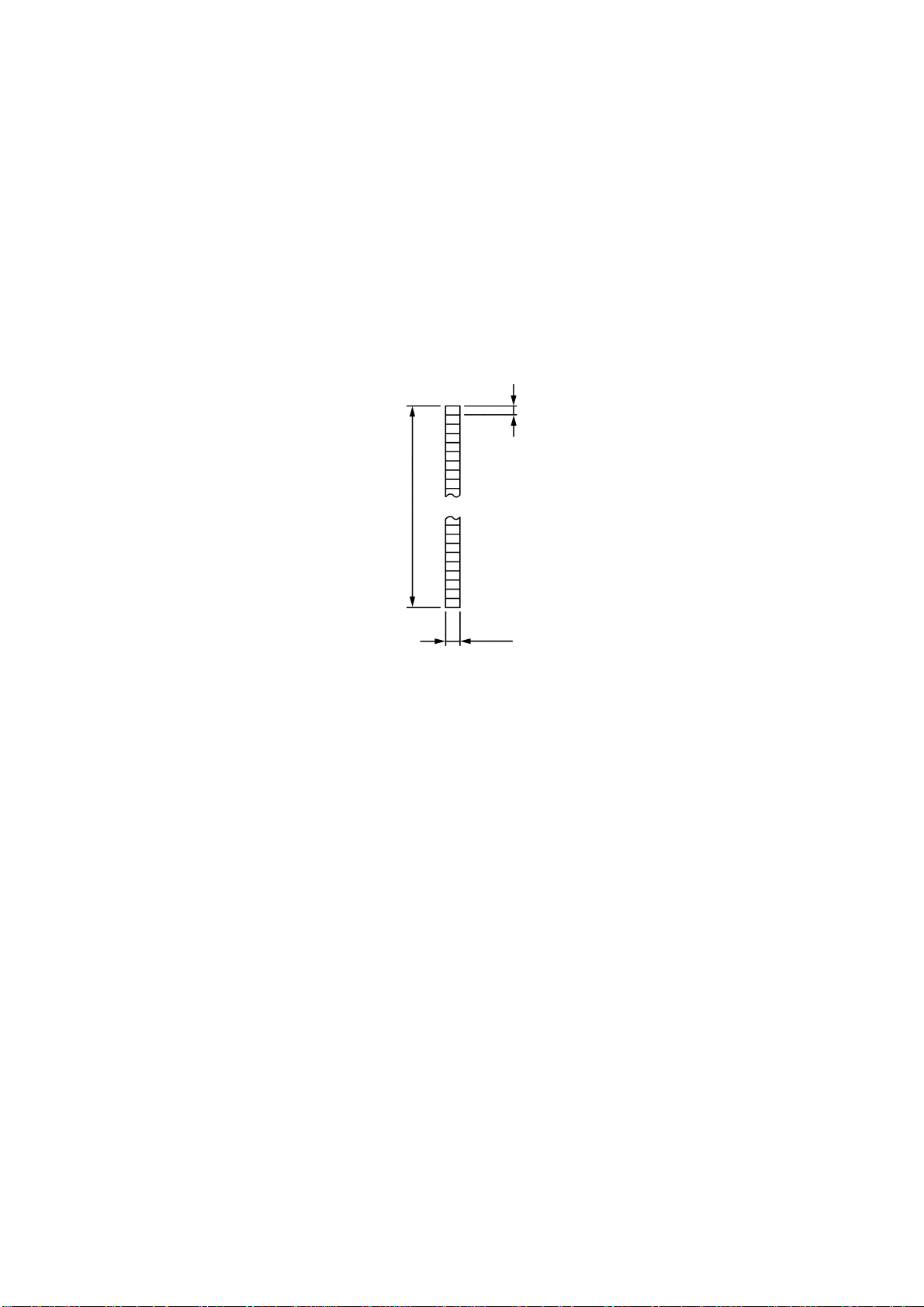
(1) Construction of thermal head
This machine uses thermal transfer printing. The thermal head contains 384
heating elements vertically arranged. The size of one heating element is
0.08 mm wide by 0.0705 mm (pitch) high, as shown in Fig. 2.1-1.
0.0705 mm (1/360”)
27.056 mm
0.08 mm
Fig. 2.1-1 Heating Elements of the Thermal Head
(2) Theory of printing
During printing operation, the cylindrical rubber platen crimps the tape* and the
ink ribbon** on the thermal head. At this time, the CPU selects the required
heating elements out of the 384 heating elements to energize them. The
theory of printing depends on the use of non-laminated thermal film tape
cassettes or other tape cassettes:
(*) Laminated tape when using laminated tape cassettes.
Non-laminated tape when using non-laminated tape cassettes.
Instant lettering tape when using instant lettering tape cassettes.
Fabric printing tape when using fabric printing tape cassettes.
Stamp tape when using stamp tape cassettes.
(**) When using non-laminated thermal film tape cassettes, no ink ribbon is
present.
II - 1

[For non-laminated thermal film tape cassettes]
If the selected heating element(s) generates heat, the thermal film tape
develops itself to produce a dot on the tape. The tape is advanced and the
next printing cycle is repeated, thus forming a character and graphics on the
tape.
When using laminated tape cassettes, instant lettering tape cassettes, or fabric
printing tape cassettes, print data is processed so that a character and
graphics read correctly when viewed from the opposite side of the printing
surface of the tape. (In other words, the mirror image of the character and
graphics is printed.)
[For stamp tape cassettes]
If the selected heating element(s) generates heat, the porous-stamp tape will
be melted so that a pore(s) will be formed in the tape. The tape is advanced
and the next heating cycle is repeated, thus forming a character of pores in the
tape. The printed stamp tape can be used as the face of a stamp. When the
stamp is pressed against the ink-pad, it will absorb ink through the pores.
(3) Character Formation
While the main motor (stepping motor) feeds the tape and ink ribbon (tape only
when using non-laminated thermal film tape cassettes or stamp tape
cassettes) by 0.0705 mm for 3.5 ms, the thermal head generates heat once.
The feed amount of 0.0705 mm is smaller than the width (0.08 mm) of the
heating elements so that the heat generated at one heating cycle will overlap
with the next heating cycle. This forms a character having no gap between
adjacent printed dots.
II - 2
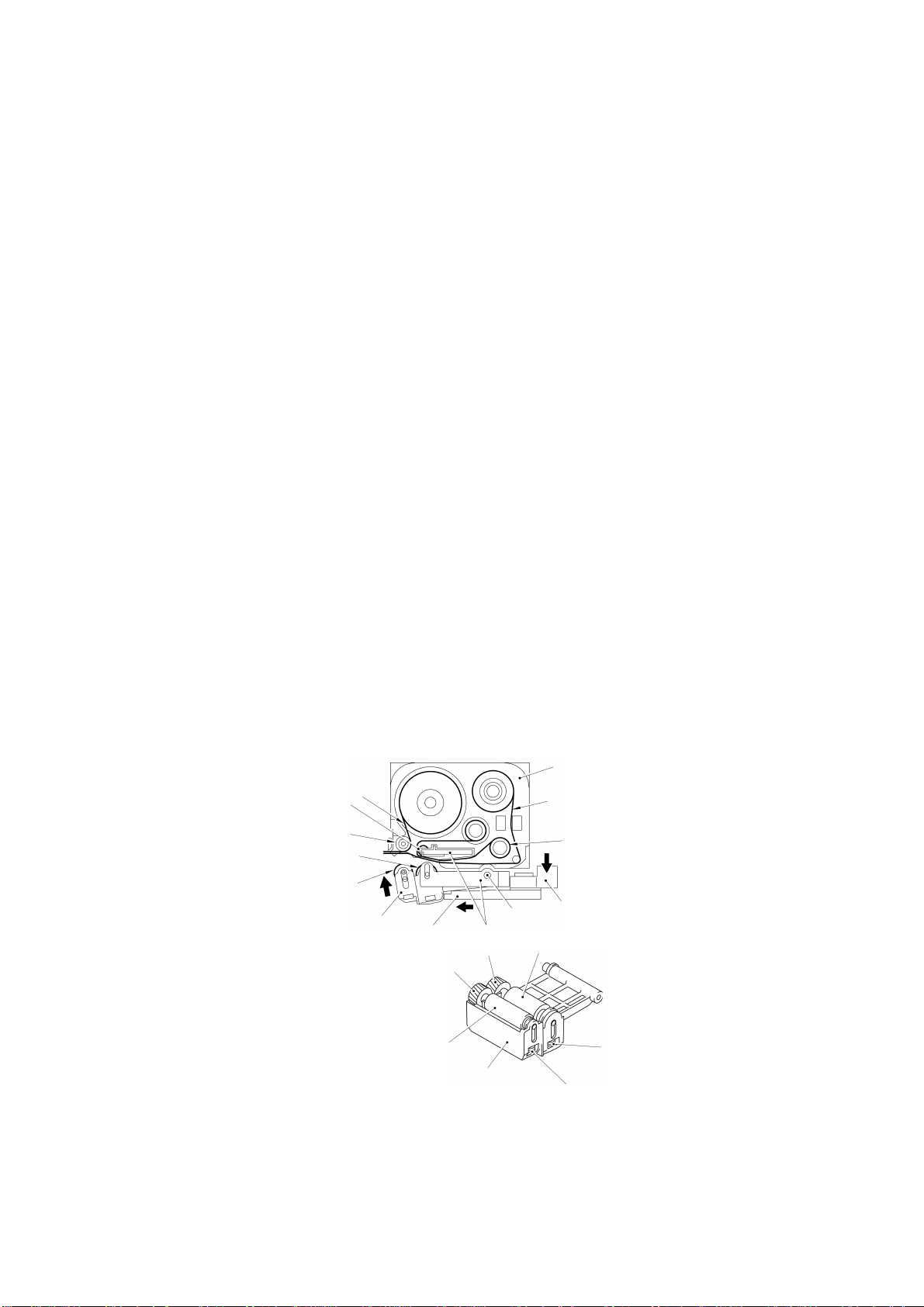
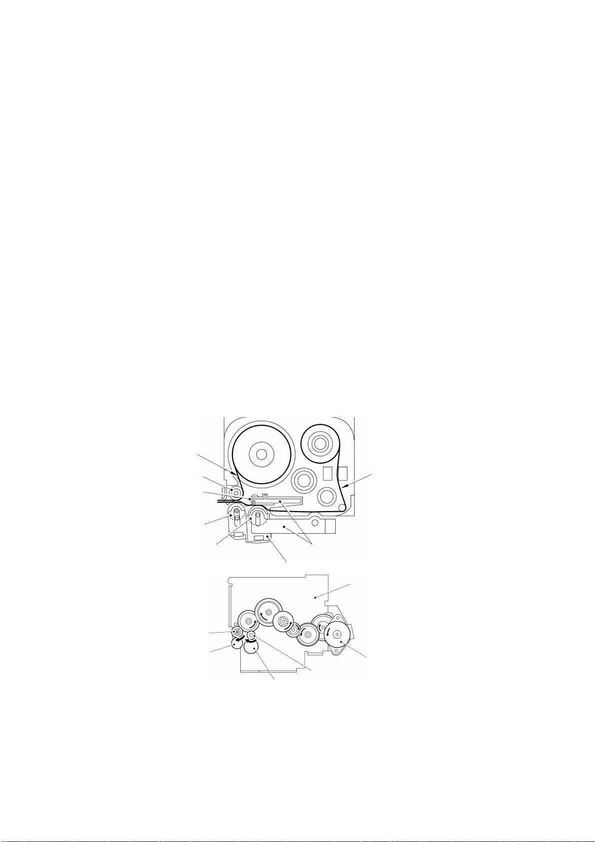
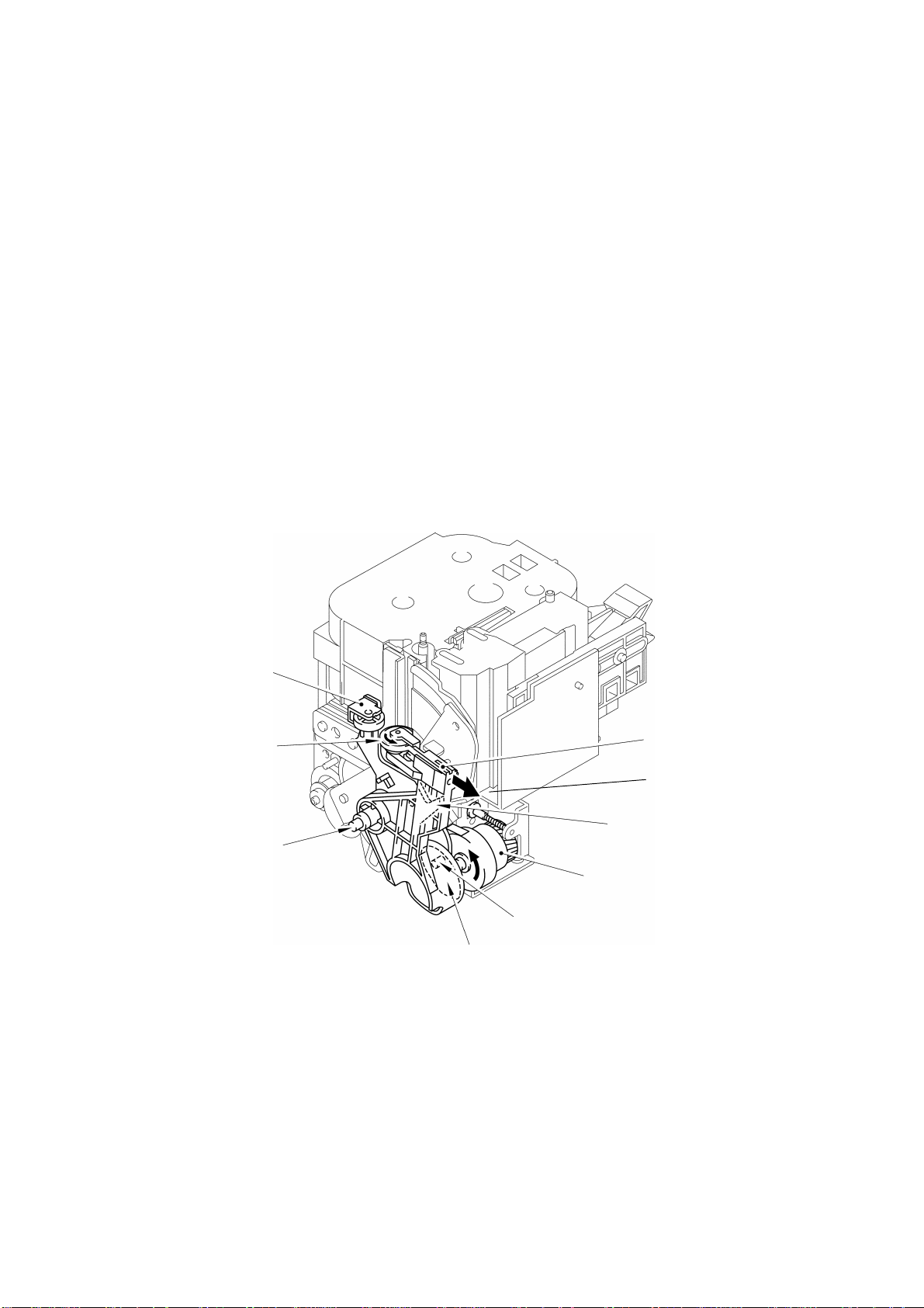
2.1.2 Roller Holder Assy Setting and Retracting Mechanism
This mechanism consists of the release cam, roller release rod, and roller
holder/head assy.
The roller holder assy incorporates the platen holder and the sub roller holder.
These holders support the platen and the tape feed sub roller so that they can
move perpendicularly to the thermal head and the tape feed roller, respectively.
The platen is pressed perpendicularly against the thermal head under a uniform
load regardless of the thickness of the tape, so that the tape is fed.
Closing the cassette cover pushes down the release cam which moves the roller
release rod to the left (when viewed from the front of the machine). This pivots the
roller holder assy around the shaft secured on the thermal head assy so as to press
the roller holder assy against the thermal head.
The platen is pressed perpendicularly against the thermal head with the tape and
ink ribbon (only the tape when using non-laminated thermal film tape cassettes or
stamp tape cassettes) sandwiched inbetween under a uniform load by the platen
spring.
At the same time, the platen gear becomes engaged with the platen idle gear.
Also, the tape feed sub roller is pressed perpendicularly against the tape feed roller
built in the tape cassette with the tape (and base paper when using laminated tape
cassettes or stamp tape cassettes) sandwiched inbetween under a uniform load by
the sub roller holder springs. At the same time, the sub roller gear becomes
engaged with the tape feed gear.
Opening the cassette cover causes the release lever spring to slide the roller
release rod in the direction of the arrow. This retracts the roller holder assy from the
thermal head, providing you with enough space to replace the tape cassette.
Tape cassette
Adhesive base tape
Platen idle gear
Tape feed roller
Platen roller
Tape feed sub roller
Roller holder assy
Roller release rod
Platen gear
Sub roller gear
Sub roller
Roller holder
Roller holder shaft
Thermal head assy
Fig. 2.1-2 Roller Holder Assy Setting and Retracting Mechanism
Laminated tape
Ink ribbon
Release cam
Platen roller
Platen spring
Sub roller spring
II - 3
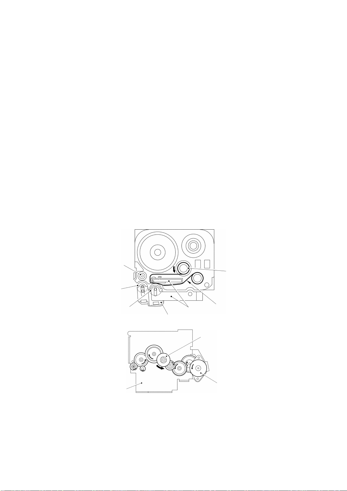
2.1.3 Regular Tape and Ribbon Feed Mechanism
This mechanism consists of the tape feed motor, the gear train, and the roller holder
assy.
(1) Regular Tape Feeding
When you load a tape cassette and close the cassette cover, the platen and
the thermal head sandwich the tape and ink ribbon (only the tape when using
non-laminated thermal film tape cassettes or stamp tape cassettes) inbetween.
Also, the tape feed sub roller in the roller holder assy and the tape feed roller
inside the tape cassette sandwich the tape (and base paper when using
laminated tape cassettes or stamp tape cassettes) inbetween, as described in
Subsection 2.1.2.
As the tape feed motor (stepping motor) rotates, the rotation is transmitted via
the gear train to the platen idle gear (which rotates the platen gear) and the
tape feed gear (which rotates the tape feed roller and the tape feed sub roller
at the same rotation speed).
Accordingly, the sandwiched tape and ink ribbon will be advanced. (When a
laminated tape cassette is mounted, the sandwiched laminated tape, adhesive
base tape, and ink ribbon will be advanced together.)
The feeding amount of the tape feed sub roller is slightly greater than that of
the platen roller.
Adhesive base tape
Tape feed roller
Platen idle gear
Tape feed sub roller
Platen roller
Tape feed gear
Sub roller gear
Transparent laminated tape
Thermal head assy
Roller holder assy
Main frame
Tape feed motor
Platen idle gear
Platen gear
Fig. 2.1-3 Tape Feed Mechanism
II - 4
(2) Adhesive Base Tape Feeding (only for laminated tape cassettes)
A laminated tape cassette contains both a transparent laminated tape roll and
a separate adhesive base tape roll.
When a transparent laminated tape and an adhesive base tape pass through
the contact point (between the tape feed roller and tape feed sub roller), they
are then bonded together into a single, printed tape. The ink printed on the
laminated tape is, therefore, sealed up with the adhesive base tape.
(3) Ink Ribbon Feeding (except for non-laminated thermal film tape cassettes and
stamp tape cassettes)
As the main motor rotates, the ribbon drive cam located at the middle of the
gear train rotates counterclockwise. When fitted on the ribbon drive cam, the
ribbon take-up roll in the tape cassette also rotates to take up the ink ribbon.
To apply proper tension to the ink ribbon between the platen roller and the
ribbon drive cam, the feed amount of the ribbon drive cam is slightly greater
than that of the tape feed gear. The difference between the feed speeds at
the platen roller and at the ribbon drive cam is absorbed by the clutch spring
which is integrated in the ribbon drive cam and allows the cam to slip.
This way, the ink ribbon is kept tense, which enables the ribbon to clearly
separate from the tape at the stabilized angle after printing.
Tape feed roller
Tape feed sub roller
Platen roller
Main frame
Ribbon take-up roll
Ink ribbon
Thermal head assy
Roller holder assy
Ribbon drive cam
Tape feed motor
Fig. 2.1-4 Ribbon Feed Mechanism
II - 5
2.1.4 Tape Automatic Full Cutter Mechanism
The tape automatic full cutter mechanism consists of a stationary blade and a
movable blade driven by the full cutter motor.
Upon completion of printing and tape feeding, the CPU activates the full cutter
motor (DC motor) whose clockwise rotation is transmitted to the cutter helical gear.
As the cutter helical gear rotates counterclockwise, its boss “A” (which is fitted in the
opening of the movable blade) actuates the movable blade to pivot it around shaft
“B”. Consequently, the cutter cuts the printed tape routing through the movable and
stationary blades, just like a pair of scissors.
Subsequently, the CPU keeps the full cutter motor on. When the movable blade
returns to the home position, part “C” of the cutter helical gear presses the full cutter
sensor switch secured on the half frame. The moment the CPU receives the sensor
signal, it stops the full cutter motor.
Stationary blade
Full cutter sensor
Fig. 2.1-5 Tape Automatic Full Cutter Mechanism
“B”
“C”
“A”
Cutter helical gear
Cutter helical gear
Movable blade
Full cutter motor assy
II - 6
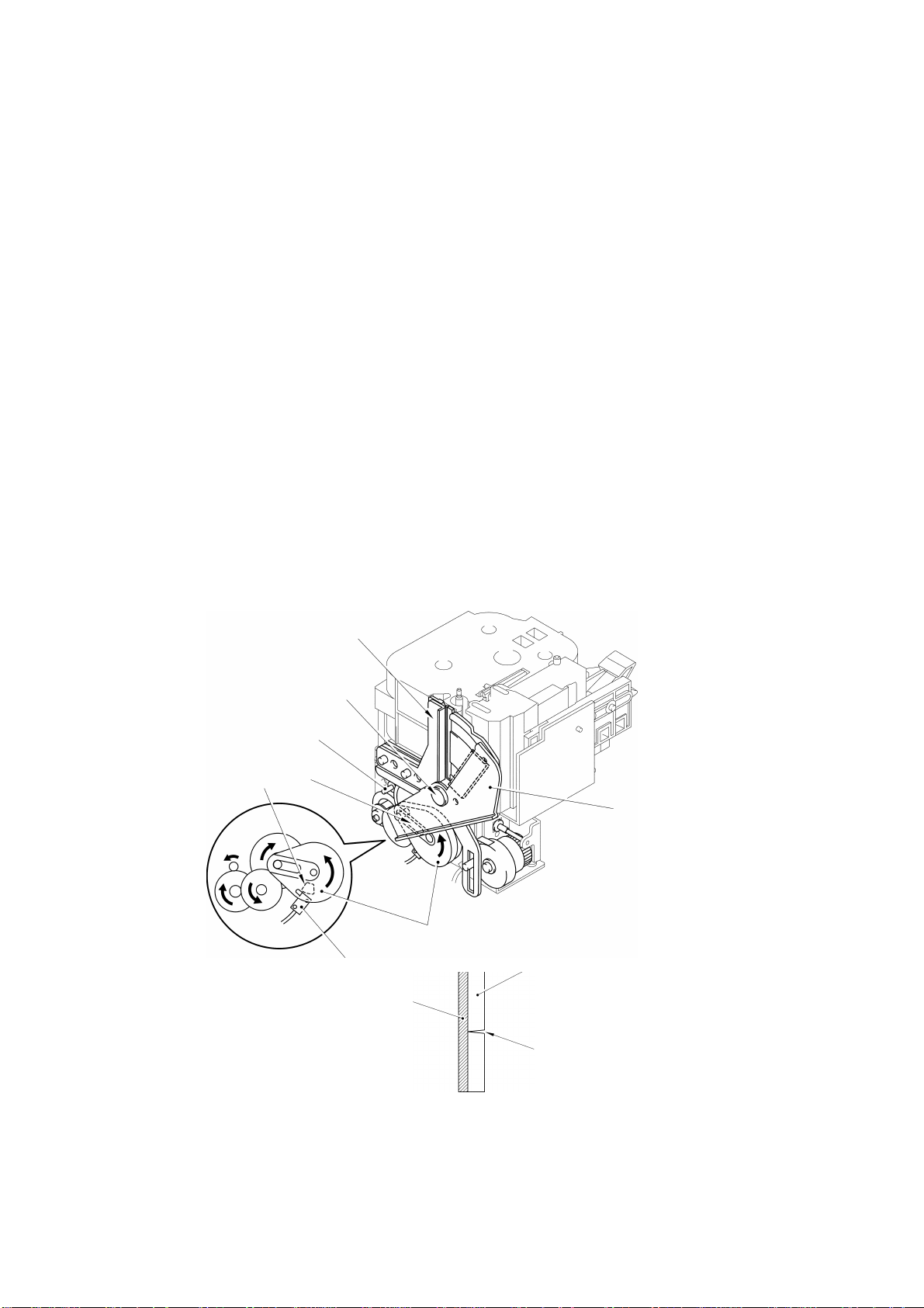
2.1.5 Tape Automatic Half Cutter Mechanism
The tape automatic half cutter mechanism consists of a stationary plate and a half
cutter holder (equipped with a cutter blade) which is operated by the half cutter
motor.
Half cutting is performed only for laminated tapes.
Upon completion of printing and tape feeding, the CPU activates the half cutter
motor (DC motor) whose counterclockwise rotation is transmitted to the half rock
gear by the clutch gear and the three idle gears.
As the half rock gear rotates counterclockwise, its groove “D” (into which the
projection on the half cutter holder is inserted) operates the half cutter holder to
pivot it around shaft “E”. The stationary plate is provided with space as wide as the
separator of a laminated tape. A laminated tape is pressed against the stationary
plate by the half cutter holder for half cutting.
Half cutting refers to cutting a tape except its separator.
Subsequently, the CPU rotates the half cutter motor counterclockwise to return the
half cutter holder to the home position. Part “F” of the half rock gear presses the
half cutter sensor switch provided on the half frame. The moment the CPU receives
the sensor signal, it stops the half cutter motor.
Stationary blade
“E”
Half cutter motor assy
“D”
“F”
Half cutter holder
Half rock gear
Half cutter sensor
Tape
Separator
Cut line
Fig. 2.1-6 Tape Automatic Half Cutter Mechanism
II - 7
2.1.6 Forced Tape Eject Mechanism
The forced tape eject mechanism consists of the stationary roller unit and the eject
roller unit interlocked with the cutter mechanism.
Upon completion of printing and tape feeding to operate the cutter mechanism, the
cutter helical gear rotates counterclockwise, as described in Subsection 2.1.4.
Projection “A” (which is fitted on cam “G” of the eject roller unit) operates the eject
roller unit to pivot it around shaft “H”. Immediately before the cutter starts cutting
the printed tape, the tape is pressed against the stationary roller by the eject roller
and held in place until the cutter completes cutting the tape. These operations of
the cutter and the eject roller unit are controlled by cam “G”.
Upon completion of the cutting of the tape by the cutter, released cam “G” causes
the spring to slide the eject roller unit in direction “J”. At this time, the two cams and
springs below the eject roller rotate the eject roller in direction “K” to eject the tape
that has been held in place.
Subsequently, the eject roller unit stops at stopper “L” of the stationary roller unit.
Stationary roller unit
“K”
“H”
Eject roller unit
“J”
“L”
Cutter helical gear
“A”
“G”
Fig. 2.1-7 Forced Tape Eject Mechanism
II - 8
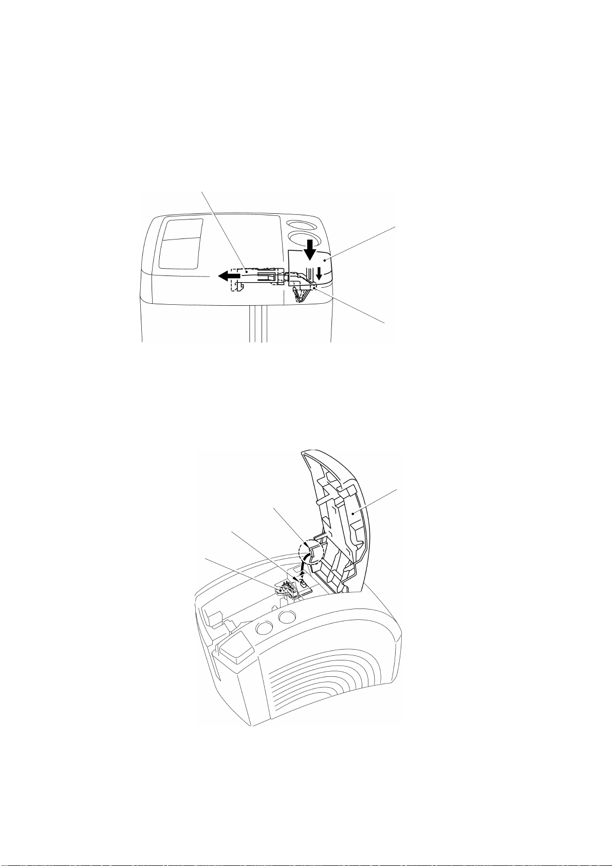
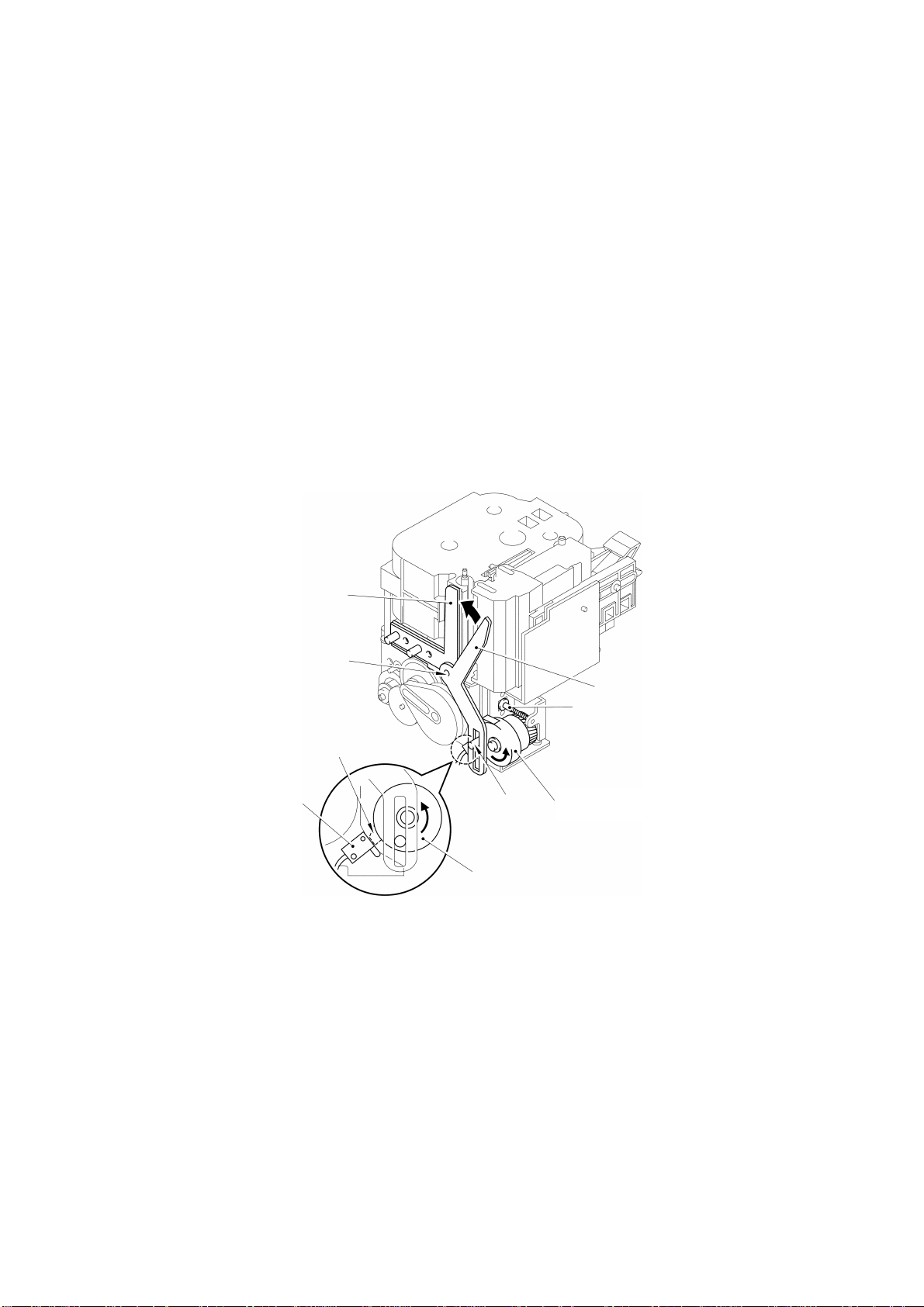
2.1.7 Cover Open Button (Cover Lock Button)
Pressing the cover open button (cover lock button) slides the cover button actuator
to the left. This presses the cover lock actuator of the cassette cover, releasing the
hook to open the cassette cover.
Cover lock actuator
Fig. 2.1-8 Cover Open Button
2.1.8 Cover Open (Cover Lock) Sensor
The cover open (cover lock) sensor (push switch) is provided on the cassette
sensor PCB. Closing the cassette cover puts its sensor tab on the cover open
(cover lock) sensor (push switch), signaling that the cassette cover is closed.
Cover open button
(Cover lock button)
Cover button actuator
Cover open switch
(push switch)
Cassette sensor PCB
Cassette cover
Sensor tab
Fig. 2.1-9 Cover Open Sensor
II - 9

2.2 DISASSEMBLY AND REASSEMBLY PT99007
Precautions on Safety
(1)Disassemble and reassemble the machine on a grounded antistatic sheet.
Touching electronic components such as an LSI with an electrified hand will
break them, as they are easily affected by static electricity.
(2)Wrap the machine in an electrically conductive aluminum sheet before carrying
it.
(3)When using heating tools such as soldering iron, take care not to thermally
break resin components such as a wire, a PCB, and a cover.
(4)Take care not to lose small components, such as a screw and a washer, which
have been removed to replace other components.
(5)Tighten screws according to the list of tightening torque below.
List of Tightening Torque
Position Screw Qty. Tightening torque [kgf·cm]
Head/roller holder unit
Eject unit
Half frame
Tape feed motor
Full cutter motor 2
Half cutter motor 2
Full cutter sensor
Half cutter sensor 1
Main frame
Tape end sensor 2
Main PCB 3
Cassette cover bracket 2
Sub PCB 2
Inlet bracket 2
Power supply PCB 2
Bottom cover
Lower cover 1
Inlet
Shield plate B
Ground wire 1
Screw, pan (S/P washer) M3×10
Screw, pan (S/P washer) M4×12
Screw, pan (S/P washer) M3×6
Screw, pan M2.6×3.5
Screw, pan M1.7×6
Taptite, bind B M2.6×8
Taptite, bind B M2.6×10
Screw, flat B M3×10
Screw, pan (S/P washer) M4×8
2
59±10 N·cm (6±1 kgf·cm)
2
88±10 N·cm (9±1 kgf·cm)
2
59±10 N·cm (6±1 kgf·cm)
2
39±10 N·cm (4±1 kgf·cm)
1
15±5 N·cm (1.5±0.5 kgf·cm)
2
39±10 N·cm (4±1 kgf·cm)
3
39±10 N·cm (4±1 kgf·cm)
2
39±10 N·cm (4±1 kgf·cm)
1
59±10 N·cm (6±1 kgf·cm)
II - 10
2.2.1 Disassembly Procedures
[1] Removing the Tape Cassette
(1) Pressing the cover open button (cover lock button) releases the hook to
open the cassette cover.
(2) Opening the cassette cover releases the platen from the thermal head
simultaneously. Hold both sides of the tape cassette and lift it to remove
it.
Tape cassette
Cover open button
(Cover lock button)
Cassette cover
Front cover
Fig. 2.2-1 Removing the Tape Cassette
<Disassembly of the Covers>
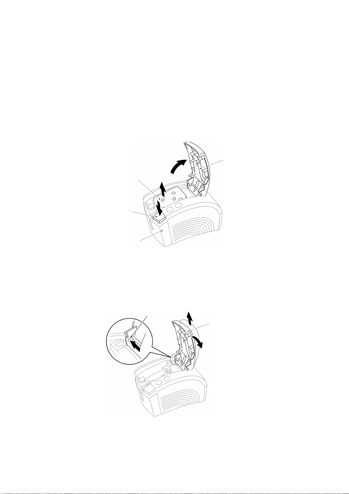
[2] Removing the Cassette Cover
While pressing part “A” with the end of a screwdriver, slightly tilt the cassette
cover with side “B” turned upwards, and lift the cassette cover to remove it.
Part “A”
Cassette cover
“B”
Fig. 2.2-2 Removing the Cassette Cover
II - 11
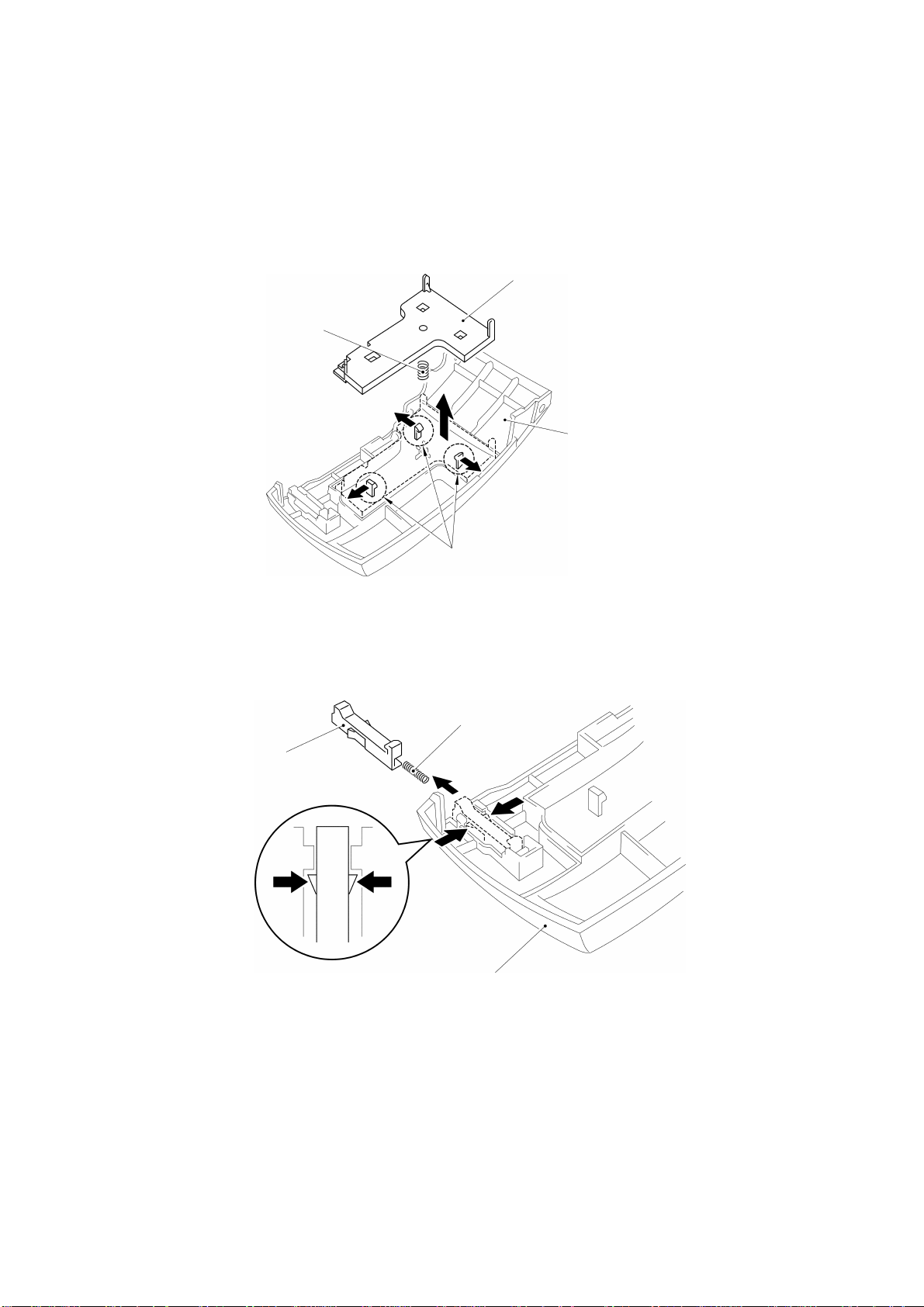
[3] Disassembly of the Cassette Cover Components
(1) Release each of the three hooks of the cassette cover securing the
cassette presser with the end of a screwdriver to remove the cassette
presser. Removing the cassette presser removes the cassette spring.
Cassette presser
Cassette spring
Cassette cover
Hooks
Fig. 2.2-3 Removing the Cassette Presser and Spring
(2) Release the hooks on both sides of the cover lock actuator with the end of
a screwdriver to remove the cover lock actuator. Removing the cover lock
actuator removes the cover lock spring.
Cover lock spring
Cover lock actuator
Cassette cover
Fig. 2.2-4 Removing the Cover Lock Actuator and Spring
II - 12
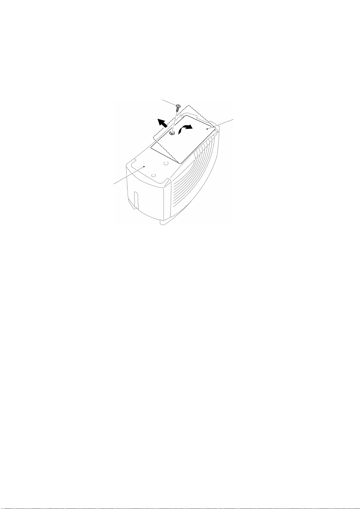
[4] Removing the Lower Cover
Turn the machine over, and remove the screw from the lower cover to remove
the lower cover.
Screw
Lower cover
Bottom cover
Fig. 2.2-5 Removing the Lower Cover
II - 13
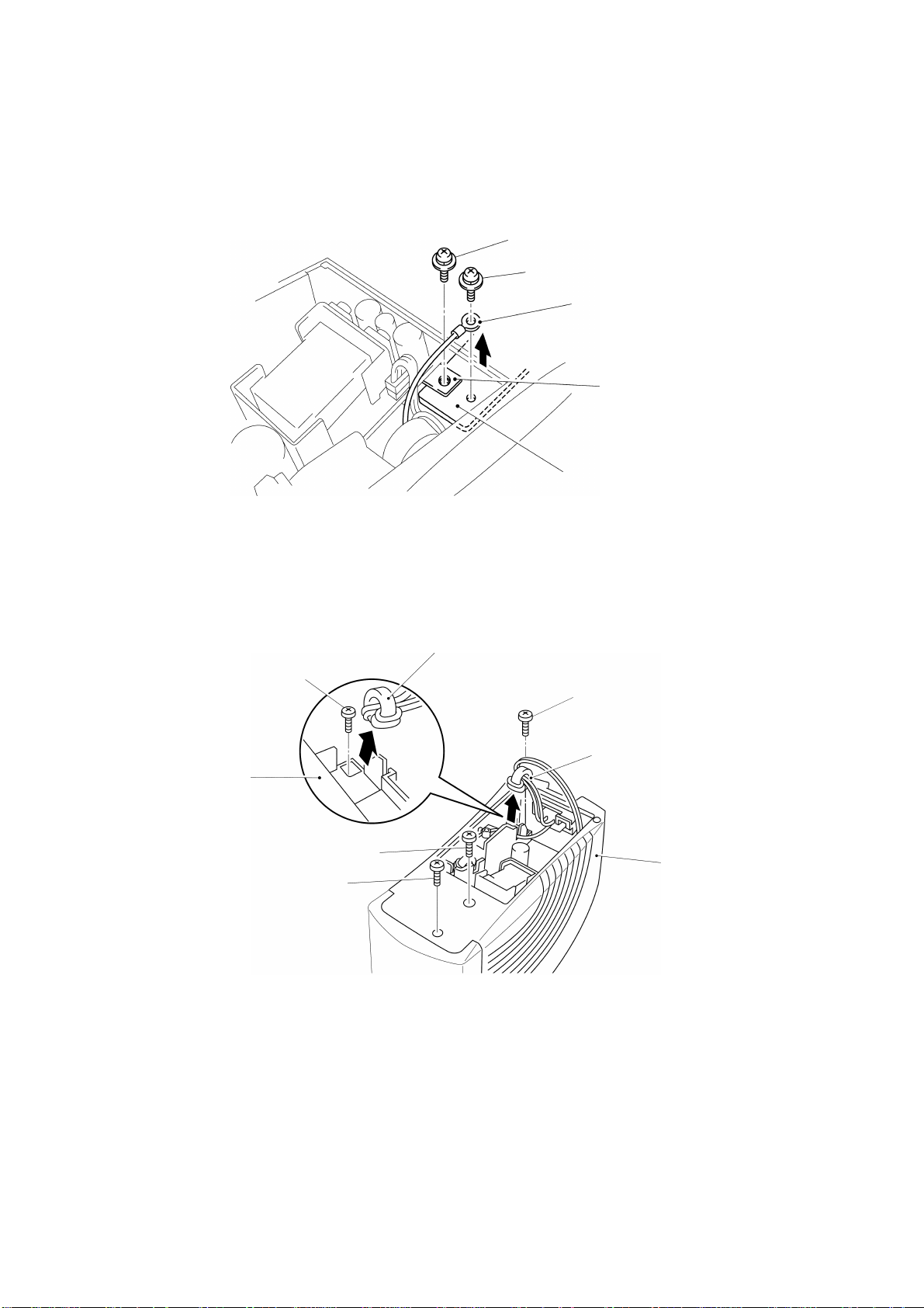
[5] Removing the Bottom Cover and the Front Cover
(1) Remove screws “A” and “B” securing the ground wire.
Screw “A”
Screw “B”
Ground wire
Shield plate B
Half frame
Fig. 2.2-6 Removing the Screws Securing the Ground Wire
(2) Remove screws “C” and “D” securing the bottom cover.
Then, remove the core of the inlet bracket unit from the storage space in
the bottom cover, before removing screw “E” securing the bottom cover.
Bottom cover
Core
Screw “E”
Screw “E”
Core
Screw “D”
Screw “C”
Bottom cover
Fig. 2.2-7 Removing the Screws Securing the Bottom Cover
II - 14
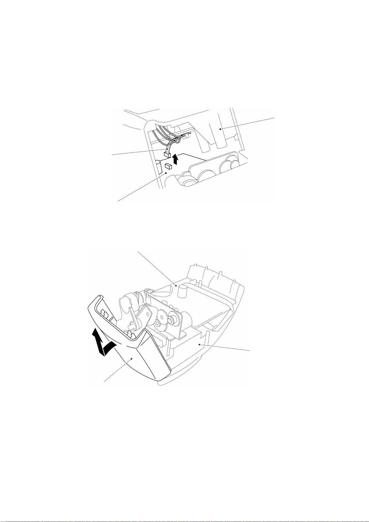
(3) While pressing the body cover, lift both sides of the bottom cover to
remove it.
(4) Pull out the power supply harness and connector from the main PCB.
Caution: Do not pull the harness; hold the connector to pull it out.
Power supply harness
Bottom cover
Main PCB
Fig. 2.2-8 Removing the Power Supply Harness and Connector
(5) While pressing the body cover, lift the front cover diagonally to remove it.
Main PCB
Body cover
Front cover
Fig. 2.2-9 Removing the Front Cover
II - 15
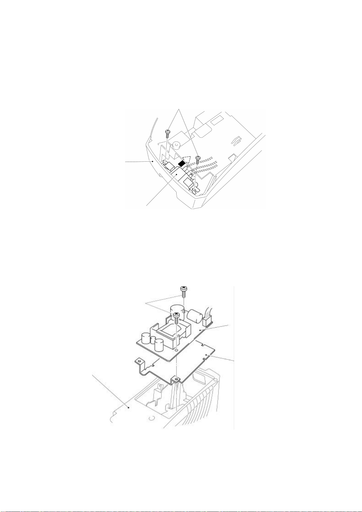
[6] Removing the Power Supply PCB Assy
(1) Remove the two screws securing the inlet bracket.
(2) Turn the bottom cover over and remove the inlet unit.
Two screws
Bottom cover
Inlet unit
Fig. 2.2-10 Removing the Inlet Unit
(3) Remove the two screws securing the power supply PCB assy.
(4) Release the power supply harness from the hook of the bottom cover, and
lift the power supply PCB assy to remove it.
(5) Lift shield plate B to remove it.
Two screws
Power supply PCB assy
Shield plate B
Bottom cover
Fig. 2.2-11 Removing the Power Supply PCB Assy and Shield Plate B
II - 16
 Loading...