

Page 1
PE-DESIGN
PE-DESIGN
Personal Embroidery Design Software System
Instruction Manual
Instruction Manual
Ver.6Ver.6
<< PE-Design Ver.6.0 >> cover 1-4
Page 2
Frontcover.fm Page 1 Thursday, July 8, 2004 1:48 PM
IMPORTANT INFORMATION: REGULATIONS
Federal Communications Commissions (FCC) Declaration of Conformity
(For USA Only)
Responsible Party: Brother International Corporation
100 Somerset Corporate Boulevard
Bridgewater, NJ 08807-0911 USA
declares that the product
Product Name: Brother USB Writer
Model Number: PE-Design
complies with Part 15 of the FCC Rules. Operation is subject to the following two conditions: (1) this
device may not cause harmful interference, and (2) this device must accept any interference
received, including interference that may cause undesired operation.
This equipment has been tested and found to comply with the limits for Class B digital device, pursuant to Part 15 of the FCC Rules. These limits are designed to provide reasonable protection against
harmful interference in a residential installation. This equipment generates, uses, and can radiate
radio frequency energy and, if not installed and used in accordance with the instructions, may cause
harmful interference to radio communications. However, there is no guarantee that interference will
not occur in a particular installation. If this equipment does cause harmful interference to radio or
television reception, which can be determined by turning the equipment off and on, the user is
encouraged to try to correct the interference by one or more of the following measures:
– Reorient or relocate the receiving antenna.
– Increase the separation between the equipment and receiver.
– Consult the dealer or an experienced radio/TV technician for help.
– Changes or modifications not expressly approved by the manufacturer or local sales distributor
could void the user’s authority to operate the equipment.
Canadian Department of Communications Compliance Statement
(For Canada Only)
This digital apparatus does not exceed the Class B limits for radio noise emission from a digital apparatus as set out in the interference-causing equipment standard entitled “Digital Apparatus”, ICES003 of the Department of Communications.
Radio Interference
(Other than USA and Canada)
This machine complies with EN55022 (CISPR Publication 22) /Class B.
Page 3
Frontcover.fm Page 2 Thursday, July 8, 2004 1:48 PM
Congratulations on choosing our product!
Thank you very much for purchasing our product. To obtain the best performance from this unit
and to ensure safe and correct operation, please read this Instruction Manual carefully, and then
keep it in a safe place together with your warranty.
Please read before using this product
For designing beautiful embroidery patterns
• This system allows you to create a wide variety of embroidery patterns and supports a wider
range of sewing attribute settings (thread density, sewing pitch, etc.). However, the final result
will depend on your particular sewing machine model. We recommend that you make a trial
sewing sample with your sewing data before sewing on the final material.
For safe operation
• Avoid dropping a needle, a piece of wire or other metallic objects into the unit or into the card
slot.
• Do not store anything on the unit.
For a longer service life
• When storing the unit, avoid direct sunlight and high humidity locations. Do not store the unit
close to a heater, iron or other hot objects.
• Do not spill water or other liquids on the unit or cards.
• Do not drop or hit the unit.
For repairs or adjustments
• In the event that a malfunction occurs or adjustment is required, please consult your nearest
service center.
Notice
This Instruction Manual does not explain how to use your computer under Windows. Please refer
to the Windows manuals.
Copyright acknowledgment
MS-DOS and Windows are registered trademarks of Microsoft Corp.
IBM is a registered trademark of International Business Machine Corporation.
Important
Using this unit for unauthorized copying of material from embroidery cards, newspapers and magazines for commercial purpose is an infringement of copyrights which is punishable by law.
Caution
The software included with this product is protected by copyright laws. This software can be used
or copied only in accordance with the copyright laws.
SAVE THESE INSTRUCTIONS
This product is intended for household use.
For additional product information and updates, visit our web site at:
www.brother.com
Page 4
Frontcover.fm Page 3 Thursday, July 8, 2004 1:48 PM
New Features of Version 6.0
Stitch generating
• Improved variable functions for satin stitch and fill stitch . . . . . . . . . . . . . . . . . . . . . . . . . . . . . . . . 173, 174
• Color gradation function. . . . . . . . . . . . . . . . . . . . . . . . . . . . . . . . . . . . . . . . . . . . . . . . . . . . . . . . . .96, 179
• Variations for region sewing:
piping stitch, concentric circle stitch, radial stitch, spiral stitch . . . . . . . . . . . . . . . . . . . . . . . . 95, 177, 178
• Variations for line sewing:
E-stitch, V-stitch . . . . . . . . . . . . . . . . . . . . . . . . . . . . . . . . . . . . . . . . . . . . . . . . . . . . . . . . . . . . . . . . . . .173
• Added the Stamp function and expanded the programmable fill stitch . . . . . . . . . . . . . . . 94, 98, 165, 176
• Automatic running pitch adjustment for running stitch. . . . . . . . . . . . . . . . . . . . . . . . . . . . . . . . . . .91, 172
• Half stitch for satin stitch, manual-punching object, etc. . . . . . . . . . . . . . . . . . . .91, 92, 93, 172, 174, 175
• Selectable stitch path. . . . . . . . . . . . . . . . . . . . . . . . . . . . . . . . . . . . . . . . . . . . . . . . . . . . . 92, 93, 174, 175
• Selectable edge pattern (turning point) for fill stitch. . . . . . . . . . . . . . . . . . . . . . . . . . . . . .92, 94, 174, 176
Editing functions
Layout & Editing
• Creates patterns larger than the hoop size . . . . . . . . . . . . . . . . . . . . . . . . . . 59, 108, 189, 194, 196, 198
• Enlarges/reduces while maintaining the density and stitching pattern . . . . . . . . . . . . . . . . . . . . . 132, 133
• Selects an object from the Sewing Order/Color dialog box . . . . . . . . . . . . . . . . . . . . . . . . . . . . . . . . . .184
• Monogramming function . . . . . . . . . . . . . . . . . . . . . . . . . . . . . . . . . . . . . . . . . . . . . . . . . . . . . . . . . . . . 162
• Automatically eliminates the background with the Cross Stitch and Photo
Stitch functions . . . . . . . . . . . . . . . . . . . . . . . . . . . . . . . . . . . . . . . . . . . . . . . . . . .116, 120, 122, 124, 125
• Improved Auto Punch function. . . . . . . . . . . . . . . . . . . . . . . . . . . . . . . . . . . . . . . . . . . . . . . . . . . . . . . . 115
• Improved stitch editing (selecting entry and exit points for each color, inserting or deleting feeds) . . .141
• Improved point editing:
Transforms lines to straight lines or curves . . . . . . . . . . . . . . . . . . . . . . . . . . . . . . . . . . . . . . . . . . . . . . 137
Selects points with arrow keys. . . . . . . . . . . . . . . . . . . . . . . . . . . . . . . . . . . . . . . . . . . . . . . . . . . . . . . . 135
Edits points without cancelling hole sewing. . . . . . . . . . . . . . . . . . . . . . . . . . . . . . . . . . . . . . . . . . . . . . 180
• Edits regions without ungrouping. . . . . . . . . . . . . . . . . . . . . . . . . . . . . . . . . . . . . . . . . . . . . . . . . . . . . . 134
• Split function for printing at actual size . . . . . . . . . . . . . . . . . . . . . . . . . . . . . . . . . . . . . . . . . . . . . . . . . 207
• Split off parts of stitch data . . . . . . . . . . . . . . . . . . . . . . . . . . . . . . . . . . . . . . . . . . . . . . . . . . . . . . . . . .143
User interface
• Changed grid interval range (1–10 mm → 0.1–25.4 mm) . . . . . . . . . . . . . . . . . . . . . . . . . . . . . . .105, 202
• Provides edit commands on the menu that appeared by right-clicking . . . . . . . . . . . . . 236, 242, 249, 253
• Added the Reference window . . . . . . . . . . . . . . . . . . . . . . . . . . . . . . . . . . . . . . . . . . . . . . . . . .10, 70, 107
• Improved the dialog box for setting sewing attributes (Beginner and Expert mode) . . . . . . . . . . . . 89, 171
Design Center
• Added the stitch simulator . . . . . . . . . . . . . . . . . . . . . . . . . . . . . . . . . . . . . . . . . . . . . . . . . . . . . . . . . . .101
• Allows the sewing order to be changed from the Sewing Order dialog box. . . . . . . . . . . . . . . . . . . . . .100
Layout & Editing
• Automatically creates appliqué data (material, position, basting, sewing). . . . . . . . . . . . . . . . . . . . . . .181
• Improved Sewing Order/Color dialog box . . . . . . . . . . . . . . . . . . . . . . . . . . . . . . . . . . . . . . . . . . . . . . . 184
• Improved stitch simulator. . . . . . . . . . . . . . . . . . . . . . . . . . . . . . . . . . . . . . . . . . . . . . . . . . . . . . . . . . . . 188
Others
• Added the .phc file format to those that can be imported . . . . . . . . . . . . . . . . . . . . . . . . . . . . . . . . . . . 127
• Organizes embroidery patterns in the Design Database . . . . . . . . . . . . . . . . . . . . . . . . . . . . . . . . . . . . 224
• Added more sample files for images, embroidery patterns and stitch patterns
Page 5
PeDesignV6Eng.book Page i Thursday, July 8, 2004 11:59 AM
Table of Contents
Before Use ................................................... 1
What You Can Do With This Software.............. 1
Automatically Create an Embroidery Pattern
From an Image........................................................ 1
Automatically Create an Embroidery Pattern
From a Photo .......................................................... 1
Easily Create Large-Size Embroidery Designs ...... 2
Have Fun Creating Embroidery Patterns
Manually.................................................................2
Create Embroidery Patterns Using All Three
Applications............................................................ 2
Overview of the Manual .................................... 3
Structure of the manual .......................................... 3
List of terms used ................................................... 3
Introduction ....................................................... 4
Applications of the software................................... 4
Package contents .................................................... 5
Optional supplies.................................................... 6
Principal parts......................................................... 6
Installation......................................................... 7
Installation procedure ............................................. 7
System requirements .............................................. 8
[STEP 1] Installing the software ............................ 8
[STEP 2] Installing the driver for the card writer
module .................................................................. 10
[STEP 3] Upgrading the USB card writer
module .................................................................. 12
Online registration................................................ 13
Uninstallation ....................................................... 13
Technical support ................................................. 13
Tips and Techniques for Creating Embroidery
Patterns........................................................... 14
Sew Types ...................................................... 15
Chapter 1
Basic Operation........................ 17
Getting Started .......................................... 18
About This Chapter......................................... 18
Automatically Creating Embroidery
Patterns...................................................... 19
Using the Auto Punch Function ...................... 19
Step1 Starting up Layout & Editing ................. 19
Step2 Opening an image file ............................ 20
Step3 Adjusting the size and position of the
image ...................................................... 21
Step4 Automatically converting the image to an
embroidery pattern.................................. 21
Step5 Displaying a preview of the embroidery
pattern..................................................... 22
Step6 Saving the embroidery pattern................ 23
Step7 Transferring the pattern to an original
card ......................................................... 24
Step8 Quitting Layout & Editing......................24
Using a Photo Stitch Function .........................25
Step1 Starting up Layout & Editing ................. 25
Step2 Opening an image file............................. 26
Step3 Adjusting the size and position of the
image ...................................................... 27
Step4 Automatically converting the image
to an embroidery pattern.........................27
Creating and Editing Embroidery
Patterns ...................................................... 30
Using Design Center.......................................30
Step1 Starting up Design Center....................... 30
Step2 Opening an image file............................. 31
Step3 Continuing to stage 2 (Line Image
stage)....................................................... 31
Step4 Editing lines............................................ 32
Step5 Continuing to stage 3 (Figure Handle
stage)....................................................... 33
Step6 Continuing to stage 4 (Sew Setting
stage)....................................................... 34
Step7 Specifying sewing attributes................... 34
Step8 Previewing the image ............................. 37
Step9 Saving the file......................................... 38
Using Layout & Editing....................................39
Step1 Importing embroidery patterns from
Design Center ......................................... 39
Step2 Adjusting the size and position of the
embroidery pattern.................................. 40
Step3 Adding shapes.........................................41
Step4 Adding text ............................................. 43
Step5 Fitting the text around the oval............... 44
Step6 Adding a circle for the center of the
sun...........................................................45
Step7 Selecting a programmable fill stitch....... 46
Step8 Adding a closed broken line for the sun’s
rays.......................................................... 48
Step9 Changing the sewing order of sun and
rays.......................................................... 49
Step10 Adjusting the rays................................... 50
Step11 Setting hole sewing.................................50
Step12 Previewing the embroidery pattern.........51
Step13 Transferring the pattern to an original
card ......................................................... 52
Step14 Saving the file ......................................... 53
Step15 Quitting Layout & Editing......................53
Using Programmable Stitch Creator ...............54
Step1 Starting up Programmable Stitch
Creator .................................................... 54
Step2 Opening a programmable stitch pattern.. 55
Step3 Drawing lines to edit the stitch pattern ... 56
Step4 Applying embossing/engraving effects .. 57
Step5 Saving the edited stitch pattern............... 58
Step6 Quitting Programmable Stitch Creator ... 58
Creating Large-Size Embroidery
Patterns ...................................................... 59
Designing a large-size embroidery pattern........... 59
Basic Operation
Design Center
Advanced Opreation
Layout & Editing
Advanced Opreation
Stitch Creator
Programmable
Advanced Opreation
Design Database
Advanced Opreation
Reference
Design Center
Reference
Layout & Editing
Reference
Stitch Creator
Programmable
Reference
Design Database
i
Page 6
PeDesignV6Eng.book Page ii Thursday, July 8, 2004 11:59 AM
Table of Contents
Step1 Starting up Layout & Editing ................. 59
Step2 Specifying a Design Page size................ 60
Step3 Creating the embroidery pattern ............. 60
Step4 Checking the embroidering order........... 61
Step5 Saving the pattern................................... 61
Step6 Transferring the pattern to an original
card ......................................................... 62
Step7 Quitting Layout & Editing...................... 63
Embroidering large-size embroidery patterns ...... 63
Step1 Attaching stabilizer to the fabric ............ 63
Step2 Marking the embroidering position ........ 63
Step3 Hooping the fabric.................................. 65
Step4 Embroidering.......................................... 65
Chapter 2
Advanced Operation ................ 67
Advanced Operations ............................... 68
About This Chapter......................................... 68
Design Center............................................ 69
Main Window .................................................. 70
Stage 1 (Original Image Stage) ..................... 71
Importing Image Data ..................................... 71
Using the wizard ................................................. 71
Importing image data from a TWAIN device ..... 72
Stage 2 (Line Image Stage) ........................... 73
Continuing to Stage 2 (Line Image Stage)...... 73
Creating a new Design Page in stage 2
(Line Image stage)............................................... 74
Drawing and erasing outlines.............................. 74
Stage 3 (Figure Handle Stage) ...................... 76
Continuing to Stage 3 (Figure Handle Stage). 76
Specifying the Design Page size ......................... 77
Creating a new Design Page in stage 3 (Figure
Handle stage)....................................................... 78
Editing Outlines............................................... 78
Selecting outlines................................................ 78
Moving outlines .................................................. 78
Scaling outlines................................................... 79
Flipping outlines horizontally or vertically......... 79
Rotating outlines ................................................. 79
Deleting outlines ................................................. 80
Editing Points in Outlines................................ 81
Moving points ..................................................... 81
Inserting points.................................................... 81
Deleting points .................................................... 81
Drawing a Broken Line.................................... 82
Stage 4 (Sew Setting Stage) .......................... 83
Continuing to Stage 4 (Sew Setting Stage) .... 83
Specifying display colors .................................... 83
Applying Sewing Attributes to Lines and
Regions........................................................... 84
Region sewing..................................................... 84
Line sewing ......................................................... 85
Using the Sewing Attributes bar ......................... 87
Specifying sewing attributes ............................... 89
Creating a gradation............................................ 96
Moving the center point of the concentric circle
stitch and radial stitch.......................................... 97
Specifying hole sewing....................................... 97
Applying and Editing Stamps .......................... 98
Applying a stamp ................................................ 98
Editing a stamp....................................................99
Viewing and Modifying the Sewing Order .....100
Checking the Stitching ..................................101
Previewing the Sewing Image.......................102
Changing realistic preview settings .................. 102
Viewing Patterns in the Reference Window .. 103
Zooming ............................................................ 103
Moving the display area frame.......................... 103
Redrawing the display area frame..................... 103
Scaling the display area frame .......................... 104
Saving ...........................................................104
Overwriting ....................................................... 104
Saving with a new name ................................... 104
Changing Software Settings.......................... 105
Changing the grid settings................................. 105
Changing the measurement units ...................... 105
Layout & Editing ......................................106
Main Window................................................. 107
Inputting Images and Embroidery
Patterns .........................................................108
Creating a Design Page................................108
Creating a new Design Page ............................. 108
Specifying the Design Page .............................. 108
Opening a Layout & Editing file....................... 109
Importing Image Data.................................... 111
Importing image data ........................................ 111
Importing image data from a TWAIN device,
such as a scanner ............................................... 111
Creating a portrait image................................... 112
Importing image data from the Clipboard......... 113
Changing the display settings of images ........... 113
Changing the Size and Position of the
Image.............................................................114
Saving the Image Data.................................. 114
Automatically Converting Image Data Into an
Embroidery Pattern .......................................115
Importing Embroidery Patterns .....................127
Importing embroidery patterns from a file........ 127
Importing embroidery patterns from Design
Center ................................................................ 128
Importing embroidery patterns from an
embroidery card ................................................ 128
Editing Embroidery Patterns .......................130
Editing Embroidery Patterns .........................130
Selecting patterns .............................................. 130
Moving patterns ................................................ 131
Scaling patterns................................................. 132
ii
Page 7
PeDesignV6Eng.book Page iii Thursday, July 8, 2004 11:59 AM
Table of Contents
Flipping patterns horizontally or vertically....... 133
Rotating patterns ............................................... 133
Grouping embroidery patterns .......................... 134
Editing Points in Embroidery Patterns .......... 135
Selecting points................................................. 135
Moving points ................................................... 135
Inserting points.................................................. 136
Deleting points .................................................. 137
Transforming straight lines into curves or curves
into straight lines............................................... 137
Moving entry/exit points and the center point .. 138
Editing Stitch Data ........................................ 140
Converting objects to stitch data ....................... 140
Editing stitch points of stitch data..................... 140
Changing colors of stitch data........................... 142
Converting stitch data to blocks ........................ 142
Splitting off parts of stitch data ......................... 143
Drawing Circles and Arcs.............................. 145
Drawing a circle or an oval............................... 145
Drawing an arc .................................................. 145
Drawing a fan shape.......................................... 146
Drawing an arc & string .................................... 147
Specifying the geometric attribute .................... 147
Drawing a Rectangle..................................... 148
Specifying the geometric attribute .................... 148
Drawing Straight Lines and Curves .............. 149
Specifying the geometric attribute .................... 150
Creating Manual Punching Data ................... 151
Entering Text................................................. 153
Specifying text attributes...................................154
Editing entered text........................................... 156
Selecting characters........................................... 157
Specifying text attributes...................................157
Specifying text arrangement ............................. 158
Transforming text.............................................. 160
Specifying TrueType text attributes.................. 161
Converting text to outline data.......................... 161
Entering Monograms..................................... 162
Specifying monogram attributes ....................... 163
Editing monograms........................................... 163
Editing monogram characters and the decorative
pattern................................................................164
Applying and Editing Stamps ........................ 165
Applying a stamp .............................................. 165
Editing a stamp..................................................166
Applying Sewing Attributes to Lines and
Regions......................................................... 167
Setting the thread color and sew type ............... 168
Specifying sewing attributes ............................. 171
Creating a gradation.......................................... 179
Specifying hole sewing ..................................... 180
Using the Applique Wizard............................... 181
Checking Embroidery Patterns ................... 182
Measuring the Distance Between Two
Points............................................................ 182
Specifying the Sewing Area..........................183
Checking and Editing the Sewing Order/
Color.............................................................. 184
Zooming ........................................................186
Zooming in........................................................186
Zooming out......................................................186
Zooming to actual size ...................................... 186
Zooming on selected objects............................. 186
Zooming Design Page to window ..................... 186
Previewing the Sewing Image.......................187
Changing realistic preview settings .................. 187
Checking the Stitching ..................................188
Checking Embroidery Pattern Information ....189
Editing User Thread Color Lists .................... 190
Viewing Patterns in the Reference Window .. 193
Zooming ............................................................ 193
Moving the display area frame.......................... 193
Redrawing the display area frame..................... 193
Scaling the display area frame .......................... 193
Saving and Printing ...................................... 194
Saving ...........................................................194
Overwriting ....................................................... 194
Saving with a new name ................................... 194
Outputting data in a different format ................195
Writing an embroidery pattern to an original
card.................................................................... 195
Writing multiple embroidery files to an original
card.................................................................... 196
Adding comments to saved .pes files................ 199
Printing.......................................................... 200
Specifying print settings.................................... 200
Checking the print image .................................. 201
Printing.............................................................. 201
Changing Software Settings .......................202
Changing the Settings...................................202
Changing the grid settings................................. 202
Changing the measurement units ...................... 202
Information for Optional Large-Size Hoop
Users .............................................................203
Creating Patterns for Multi-Position Hoops ... 203
Selecting the Design Page size.......................... 203
Creating the pattern........................................... 204
Optimizing hoop changes.................................. 204
Checking the pattern ......................................... 205
Saving the pattern..............................................206
Writing the pattern to an original card ..............206
Printing a Design Page for a multi-position
hoop...................................................................207
Programmable Stitch Creator................. 208
Main Window................................................. 208
Opening a Pattern File ..................................209
Creating a new pattern ...................................... 209
Opening a pattern file ........................................ 209
Opening an image in the background................ 210
Basic Operation
Design Center
Advanced Opreation
Layout & Editing
Advanced Opreation
Stitch Creator
Programmable
Advanced Opreation
Design Database
Advanced Opreation
Reference
Design Center
Reference
Layout & Editing
Reference
Stitch Creator
Programmable
Reference
Design Database
iii
Page 8
PeDesignV6Eng.book Page iv Thursday, July 8, 2004 11:59 AM
Table of Contents
Selecting a Pattern To Be Created ............... 210
Viewing the Stitch Pattern While
Creating It ..................................................... 212
Drawing a Stitch Pattern in Fill/Stamp
Mode............................................................. 212
Editing a Stitch Pattern in Fill/Stamp Mode... 213
Selecting patterns.............................................. 213
Moving patterns ................................................ 213
Scaling patterns................................................. 214
Deleting patterns ............................................... 214
Cutting out patterns........................................... 214
Copying patterns ............................................... 214
Duplicating patterns.......................................... 214
Pasting a cut or copied pattern .......................... 214
Flipping patterns vertically ............................... 215
Flipping patterns horizontally ........................... 215
Rotating patterns ............................................... 215
Editing Points in Fill/Stamp Mode................. 216
Moving points ................................................... 216
Inserting points.................................................. 216
Deleting points .................................................. 217
Creating a Stamp.......................................... 217
Creating a Stitch Pattern in Motif Mode ........ 218
Editing a Stitch Pattern in Motif Mode........... 219
Moving and deleting several points at a time.... 219
Scaling patterns................................................. 220
Flipping a pattern horizontally or vertically...... 220
Saving........................................................... 221
Overwriting ....................................................... 221
Saving with a new name ................................... 221
Changing the Settings................................... 222
Changing the display of the background image 222
Changing the grid settings................................. 222
Design Database ..................................... 223
Main Window ................................................ 223
Starting Up Design Database ....................... 224
Organizing Embroidery Patterns................... 224
Creating new folders......................................... 224
Moving/copying embroidery patterns to a different
folder ................................................................. 224
Changing the name of the embroidery pattern.. 225
Deleting an embroidery pattern......................... 225
Changing the contents pane display.................. 226
Opening Embroidery Patterns....................... 227
Opening embroidery patterns with Layout &
Editing............................................................... 227
Importing embroidery patterns into Layout &
Editing............................................................... 227
Checking Embroidery Patterns .....................227
Previewing embroidery patterns ....................... 227
Checking embroidery pattern information ........ 228
Searching for an Embroidery Pattern............ 229
Converting Embroidery Patterns to Different
Formats......................................................... 230
Outputting a Catalog of Embroidery
Patterns.........................................................231
Printing.............................................................. 231
Outputting as an HTML file.............................. 231
Outputting as a CSV file ................................... 232
Chapter 3
Reference ................................ 233
Design Center ..........................................234
List of Tool Box Buttons................................234
Stage 2 (Line Image stage) ................................. 234
Stage 3 (Figure Handle stage) ............................ 234
Stage 4 (Sew Setting stage) ................................ 235
List of Menus................................................. 236
File menu............................................................236
Edit menu............................................................ 237
Sew menu ........................................................... 238
Display menu...................................................... 238
Option menu....................................................... 239
Stage menu ......................................................... 239
Help menu .......................................................... 240
Layout & Editing ......................................241
List of Tool Box Buttons................................241
List of Menus................................................. 242
File menu............................................................242
Edit menu............................................................ 243
Image menu ........................................................ 245
Text menu........................................................... 246
Sew menu ........................................................... 246
Display menu...................................................... 247
Option menu....................................................... 248
Help menu .......................................................... 248
Programmable Stitch Creator................. 249
List of Tool Box Buttons................................249
List of Menus................................................. 249
File menu............................................................249
Mode menu......................................................... 250
Edit menu............................................................ 250
Display menu...................................................... 251
Help menu .......................................................... 252
Design Database...................................... 253
List of Menus................................................. 253
File menu............................................................253
Edit menu............................................................ 254
Display menu...................................................... 254
Option menu....................................................... 255
Help menu .......................................................... 255
Index .........................................................256
Read the following before opening the CD-ROM
package
Product Agreement
iv
Page 9
PeDesignV6Eng.book Page 1 Thursday, July 8, 2004 11:59 AM
Before Use
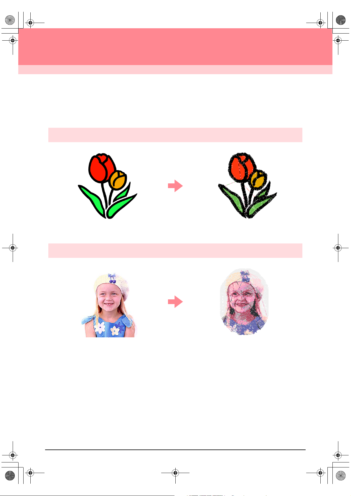
What You Can Do With This Software
This software provides digitizing and editing capabilities, allowing you the creative freedom to design original
embroidery. Easily turn illustrations, photos and lettering into custom embroidery designs.
Automatically Create an Embroidery Pattern From an Image
For more details, refer to “Using the Auto Punch Function” on page 19.
c
Automatically Create an Embroidery Pattern From a Photo
For more details, refer to “Using a Photo Stitch Function” on page 25.
c
1
Page 10
PeDesignV6Eng.book Page 2 Thursday, July 8, 2004 11:59 AM
Before Use
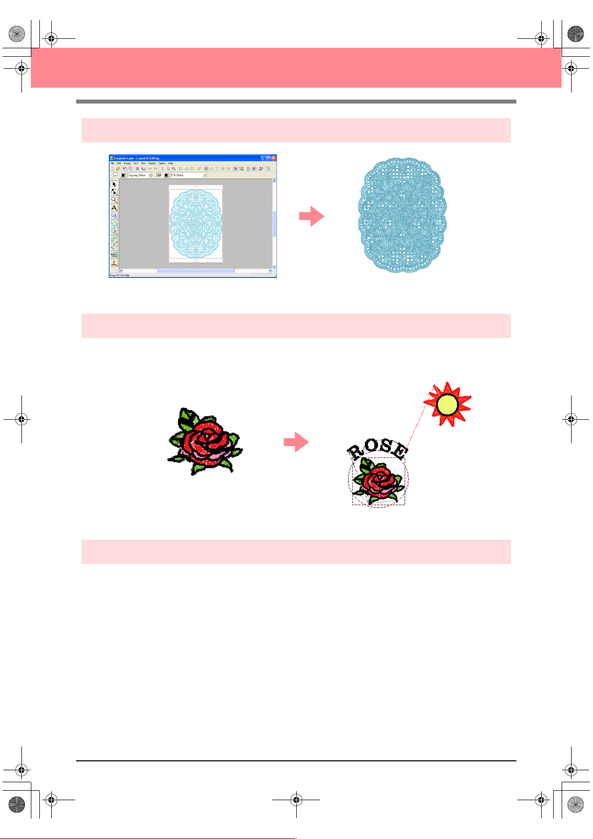
Easily Create Large-Size Embroidery Designs
For more details, refer to “Creating Large-Size Embroidery Patterns” on page 59.
c
Have Fun Creating Embroidery Patterns Manually
You can combine embroidery patterns or apply stitching to drawings and text. In addition, you can design a
wider variety of embroidery patterns by using the many sew types available.
For more details, refer to “Creating and Editing Embroidery Patterns” on page 30.
c
Create Embroidery Patterns Using All Three Applications
■ Design Center
Refer to “Using Design Center” on page 30.
c
For more details, refer to pages 69 through 105.
c
■ Layout & Editing
Refer to “Automatically Creating Embroidery Patterns” on page 19.
c
Refer to “Using Layout & Editing” on page 39.
c
For more details, refer to pages 106 through 207.
c
■ Programmable Stitch Creator
Refer to “Using Programmable Stitch Creator” on page 54
c
For more details, refer to pages 208 through 222.
c
2
Page 11
PeDesignV6Eng.book Page 3 Thursday, July 8, 2004 11:59 AM
Before Use
Overview of the Manual
Structure of the manual
This manual consists of three main sections: Basic Operation, Advanced Operation, and Reference.
■ Basic Operation
By following the step-by-step instructions contained in this section, you can create basic embroidery
patterns. For first time users, this is a good way to become familiar with the various functions.
■ Advanced Operation
This section separately outlines the capabilities and use for each application, allowing you to create more
advanced and original embroidery patterns than those created in Basic Operation.
■ Reference
This section contains an explanation of the Tool Box and a summary of the menu for each application. You
can use this section to clarify the purpose and use of any icon or menu command.
List of terms used
The following terms are used throughout this manual, as described below.
Embroidery pattern: An embroidery design
Object: A component of the embroidery pattern
Multi-position hoop: An embroidery frame that can be attached to the embroidery machine at various positions
so that large-size patterns can be sewn
Sew type: A type of stitching (for example, zigzag stitch, running stitch and satin stitch)
Stitching: A series of stitches
3
Page 12
PeDesignV6Eng.book Page 4 Thursday, July 8, 2004 11:59 AM
Before Use
Introduction
Applications of the software
This package consists of four applications.
■ Design Center
Design Center is used to manually create embroidery patterns from images. The images may come from
scanning a printed image or can be created with an application like Paint
must be .bmp, .tif, .jpg, .j2k, .pcx, .wmf, .png, .eps, .pcd, or .fpx. Design Center automatically detects outlines
in the image and replaces them with broken lines that can be edited and assigned sewing attributes.
The procedure is divided into four stages:
❏ Stage 1 (Original Image stage): Open an image file and select one or more colors that the application
will use to trace the outlines.
❏ Stage 2 (Line Image stage): The original color image is replaced with a black-and-white image (the
colors selected in stage 1 (Original Image stage) become black, and all other colors become white).
This image can be edited using pens and erasers of different thicknesses. (You can also start with this
step to draw a black-and-white image by hand.)
When the image is ready, start the automatic tracing process.
❏ Stage 3 (Figure Handle stage): The black-and-white image is replaced with a set of outlines made of
editable broken lines. You can edit the broken lines by moving, inserting or deleting editing points.
❏ Stage 4 (Sew Setting stage): In this final step, apply sewing attributes (thread color and sew type) to
the outlines and the inside regions.
At any stage, you can save your work to retrieve it later. In stage 1 (Original Image stage) and stage 2 (Line
Image stage), the file will be saved with the .pel extension. In stage 3 (Figure Handle stage) and stage 4 (Sew
Setting stage), the file will be saved with the .pem extension. In addition, if the imported image has not yet
been saved, it can be saved with the .bmp extension.
Saving your work as you move through the stages will be helpful if you make changes, then later decide to use
the original pattern.
When your image has reached stage 4 (Sew Setting stage), you can import it into Layout & Editing, where the
image can be moved and scaled as a single object.
®
. The extension of the image files
■ Layout & Editing
Layout & Editing is used to automatically create embroidery patterns from images, and to combine images and text to
create embroidery patterns that can be written to an original card. The images may come from scanning a printed image
or can be created with an application like Paint
.png, .eps, .pcd, or .fpx. In addition, the following types of embroidery patterns can be incorporated into the embroidery
pattern.
❏ Embroidery patterns created with Design Center
❏ Embroidery patterns on embroidery cards purchased from your dealer (Some patterns cannot be read.)
❏ Embroidery patterns in the Tajima (.dst), Melco (.exp), Pfaff (.pcs), Husqvarna (.hus) and embroidery
sewing machine (.phc) formats
❏ Embroidery patterns created within Layout & Editing itself (These patterns include text, circular shapes,
boxes, polygons, curves and manual punching patterns.)
After gathering the different parts of your embroidery pattern, you can use the layout functions to adjust their
relative position, orientation and scale.
When an embroidery pattern is complete, you can save it (with the .pes file extension) and write it to an original card.
The original card can then be inserted into your sewing machine for the embroidery pattern to be sewn.
®
. The extension of the image files must be .bmp, .tif, .jpg, .j2k, .pcx, .wmf,
4
Page 13
PeDesignV6Eng.book Page 5 Thursday, July 8, 2004 11:59 AM
Before Use
■ Programmable Stitch Creator
Programmable Stitch Creator allows you to create, edit and save fill/stamp and motif stitch patterns that can
be applied as a programmable fill stitch or motif stitch, or as a stamp to the enclosed regions of embroidery
patterns both in Design Center and Layout & Editing. The fill/stamp stitch patterns are saved as .pas files, and
the motif stitch patterns are saved as .pmf files. The application comes with a number of .pas and .pmf files
that you can use as they are or edit to enhance your embroidery patterns.
■ Design Database
Design Database allows you to easily preview the embroidery pattern files on your computer so that you can
find the desired pattern, which can be opened with or imported into Layout & Editing. From Design Database,
you can also convert the files to other formats (.pes, .dst., .exp., .pcs or .hus), or print or output as an HTML
file images of the embroidery patterns in a selected folder. In addition, the sewing information for the
embroidery patterns in a selected folder can be outputted as a CSV file for use in other database applications.
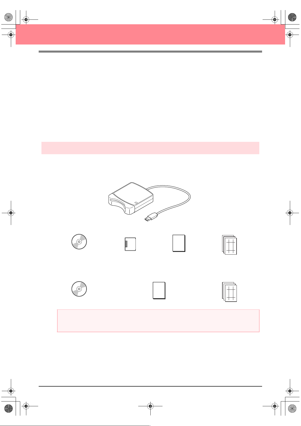
Package contents
Check that the following items are included. If anything is missing or damaged, contact your service
representative.
Version 6.0 or version 6.0 upgrade for versions 1.0 through 4.0:
USB card writer module
CD-ROM Original card Instruction manual
Version 6.0 upgrade for version 5.0:
CD-ROM Instruction manual
a Note:
The USB card writer module and the original card are not included in the kit provided for upgrading from
version 5.0.
Te mp l at e
Te m p la t e
5
Page 14
PeDesignV6Eng.book Page 6 Thursday, July 8, 2004 11:59 AM
Optional supplies
a Note:
The only original cards that can be used with this USB card writer module are those like the one enclosed
or optional original cards of the same type.
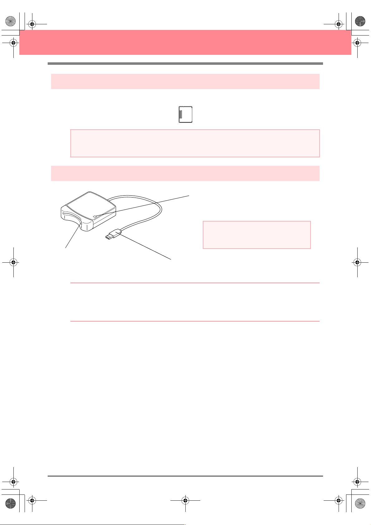
Principal parts
Before Use
Original card
LED indicator
This indicator lights up when the unit is turned on,
and flashes when the USB card writer module is
communicating with the computer.
Card slot
Insert an original card/embroidery
card here.
b Memo:
• Since power is supplied to the USB card writer module through the USB connection to the computer,
there is no power supply cable or power switch.
• Be sure to keep original cards away from high humidity, direct sunlight, static electricity and strong
shocks. Furthermore, do not bend the cards.
a Note:
Never remove an original card or unplug the
USB cable while this indicator is flashing.
USB connector
Connect to the computer.
6
Page 15
PeDesignV6Eng.book Page 7 Thursday, July 8, 2004 11:59 AM
Before Use
Installation
Installation procedure
The installation procedure is different depending on whether the full version or an upgrade of the software is
being installed. Be sure to perform the installation procedures listed below.
Installing version 6.0 (full version)
[STEP 1] Installing the software c page 8
[STEP 2] Installing the driver for the card writer module
c page 10
Upgrading from version 1.0 through 4.0
[STEP 1] Installing the software c page 8
[STEP 2] Installing the driver for the card writer module
c page 10
Upgrading from version 5.0 or 5.01
[STEP 1] Installing the software c page 8
[STEP 2] Installing the driver for the card writer module
[STEP 3] Upgrading the USB card writer module
c page 10
c page 12
Upgrading from version 5.02 or later
[STEP 1] Installing the software c page 8
b Memo:
When upgrading from version 5.02 or later, STEP 2 is not performed.
[STEP 3] Upgrading the USB card writer module c page 12
a Note:
• If the installation is interrupted or not performed as described, the software will not be installed correctly.
• Before turning on the computer, be sure to disconnect the USB card writer module. If the
computer is turned on while the card writer is connected, the installation may not be completed
correctly when upgrading from version 5.0 or 5.01.
• In order to upgrade the USB card writer module, you must be able to connect to the Internet. If you
cannot connect to the Internet, contact your nearest service representative.
7
Page 16
PeDesignV6Eng.book Page 8 Thursday, July 8, 2004 11:59 AM
Before Use
System requirements
Before installing the software on your computer, make sure that the computer meets the following
requirements.
Computer IBM-PC or compatible computer originally equipped with a USB port
Operating system Windows 98, ME, XP or 2000
Processor Pentium 500 MHz or higher
Memory Minimum 64 MB (256 MB or more is recommended.)
Hard disk free space Minimum 100 MB
Monitor SVGA (800 × 600), 16-bit color or higher
Port USB Ver. 1.1 or higher
Printer A graphic printer that is supported by your system (if you wish to print your images)
CD-ROM drive Required for installation
a Note:
• Power is supplied to the USB card writer module through the USB connection. Connect the USB card
writer module to a USB connector on the computer or to a self-powered USB hub that can supply
enough power to the card writer module. If the card writer module is not connected in this way, it may
not operate correctly.
• This product may not operate correctly with some computers and USB expansion cards.
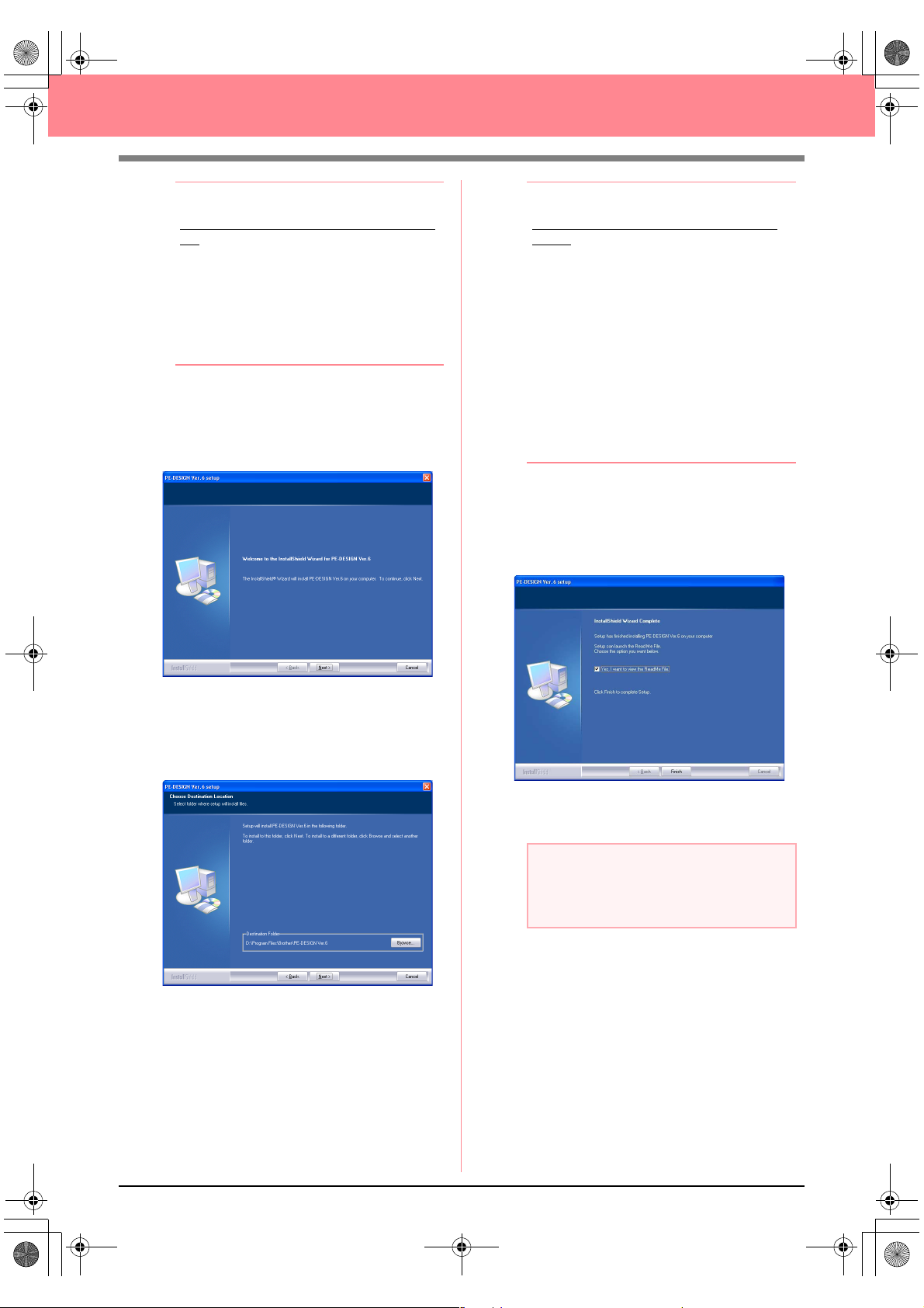
[STEP 1] Installing the software
This section describes how to install the application software.
a Note:
• If the installation is interrupted or not performed as described, the software will not be installed correctly.
• Before turning on the computer, be sure to DISCONNECT the USB card writer module.
b Memo:
The following installation procedure includes descriptions and dialog boxes for Windows XP. The
procedure and dialog boxes for other operating systems may be slightly different.
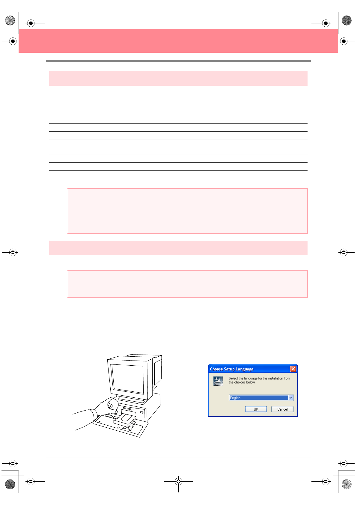
1. Insert the enclosed CD-ROM into the
computer’s CD-ROM drive.
→ After a short while, the Choose Setup
Language dialog box automatically ap-
pears.
8
Page 17
PeDesignV6Eng.book Page 9 Thursday, July 8, 2004 11:59 AM
Before Use
b Memo:
If the installer does not automatically start
up:
1) Click the Start button.
2) Click Run.
→
The Run dialog box appears.
3) Type in the full path to the installer, and
then click OK to start up the installer.
For example: D:\setup.exe (where “D:”
is the name of the CD-ROM drive)
2. Select the desired language, and then click
OK.
→ The InstallShield Wizard starts up, and
the first dialog box appears.
b Memo:
To install the application into a different
folder:
1) Click Browse.
2) In the Choose Folder dialog box that
appeared, select the drive and folder. (If
necessary, type in the name of a new
folder.)
3) Click OK.
→
The Choose Destination Location
dialog box of the InstallShield Wizard
shows the selected folder.
4) Click Next to install the application into
the selected folder.
• To return to the previous step, click
• To quit the installation, click
4. Click Next to install the application into the
default folder.
→ When the installation is completed, the di-
alog box shown below appears.
Cancel
Back
.
.
3. Click Next to continue with the installation.
→ A dialog box appears, allowing you to se-
lect the folder where the software will be
installed.
5. Click Finish to complete the installation of the
software.
a Note:
Even though the installation is completed, do
not remove the CD-ROM from the
computer’s CD-ROM drive.
9
Page 18
PeDesignV6Eng.book Page 10 Thursday, July 8, 2004 11:59 AM
Before Use
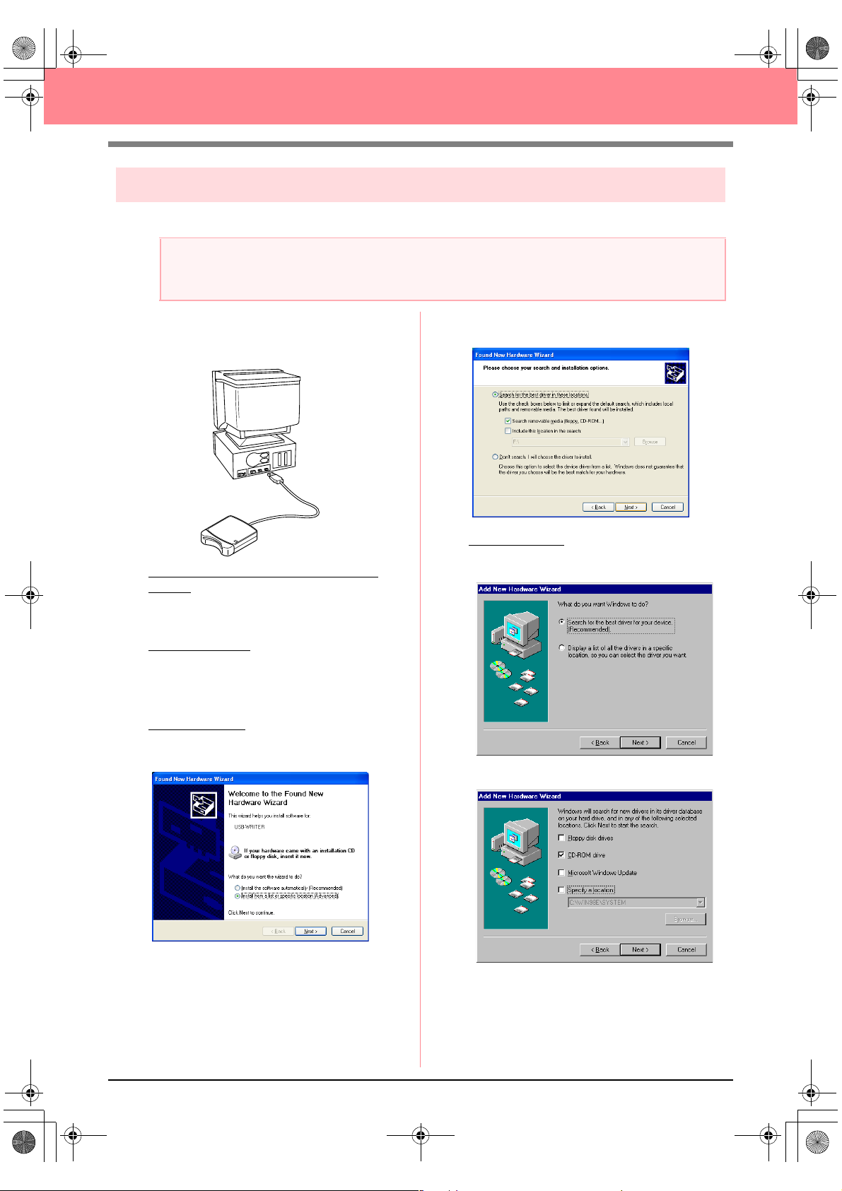
[STEP 2] Installing the driver for the card writer module
This section describes how to install the driver for the card writer module.
a Note:
If you upgrading from version 5.02 or later, skip this section and continue with the procedure described in
“[STEP 3] Upgrading the USB card writer module” on page 12.
1. Plug the USB connector into the USB port on
the computer.
Make sure that the connector is fully inserted.
For Windows XP users connected to the
Internet:
→ The installation of the driver is completed
automatically.
For all other users
→ After a short while, the Found New Hard-
ware Wizard (or Add New Hardware
Wizard) dialog box appears.
:
2. For Windows XP: Select Install from a list or
specific location [Advanced], and then click
Next.
Select Search removable media (floppy,
CD-ROM...), and then click Next.
For Windows 98:
driver for your device. (Recommended),
and then click Next.
Select CD-ROM drive, and then click Next.
Select Search for the best
10
Page 19
PeDesignV6Eng.book Page 11 Thursday, July 8, 2004 11:59 AM
Before Use
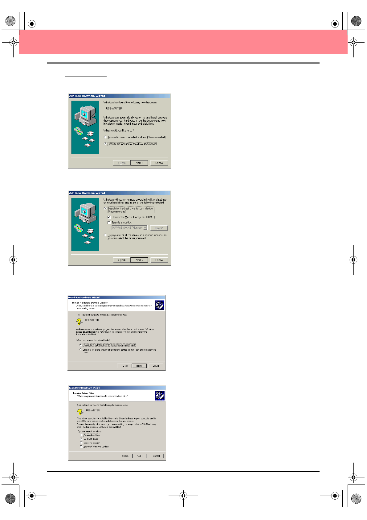
For Windows Me: Select Specify the location
of the driver [Advanced], and then click
Next.
Select Removable Media (Floppy, CDROM...), and then click Next.
3. Follow the instructions of the Found New
Hardware Wizard (or Add New Hardware
Wizard) to complete the installation of the
driver.
4. Remove the CD-ROM from the computer’s
CD-ROM drive.
For Windows 2000:
suitable driver for my device
[recommended], and then click Next.
Select CD-ROM drives, and then click Next.
Select Search for a
11
Page 20
PeDesignV6Eng.book Page 12 Thursday, July 8, 2004 11:59 AM
Before Use
[STEP 3] Upgrading the USB card writer module
This section describes how to upgrade the USB card writer module for version 6.0. Users upgrading from
version 5.0 or later must upgrade the card writer. After installing version 5.0 or later, immediately follow the
procedure below to upgrade the card writer for version 6.0.
a Note:
• If the USB card writer module is not upgraded, Design Center and Layout & Editing of version 6.0 can
no longer be used after the specified number of trial uses has been reached.
• In order to upgrade the USB card writer module, you must be able to connect to the Internet. If you
cannot connect to the Internet, contact your nearest service representative.
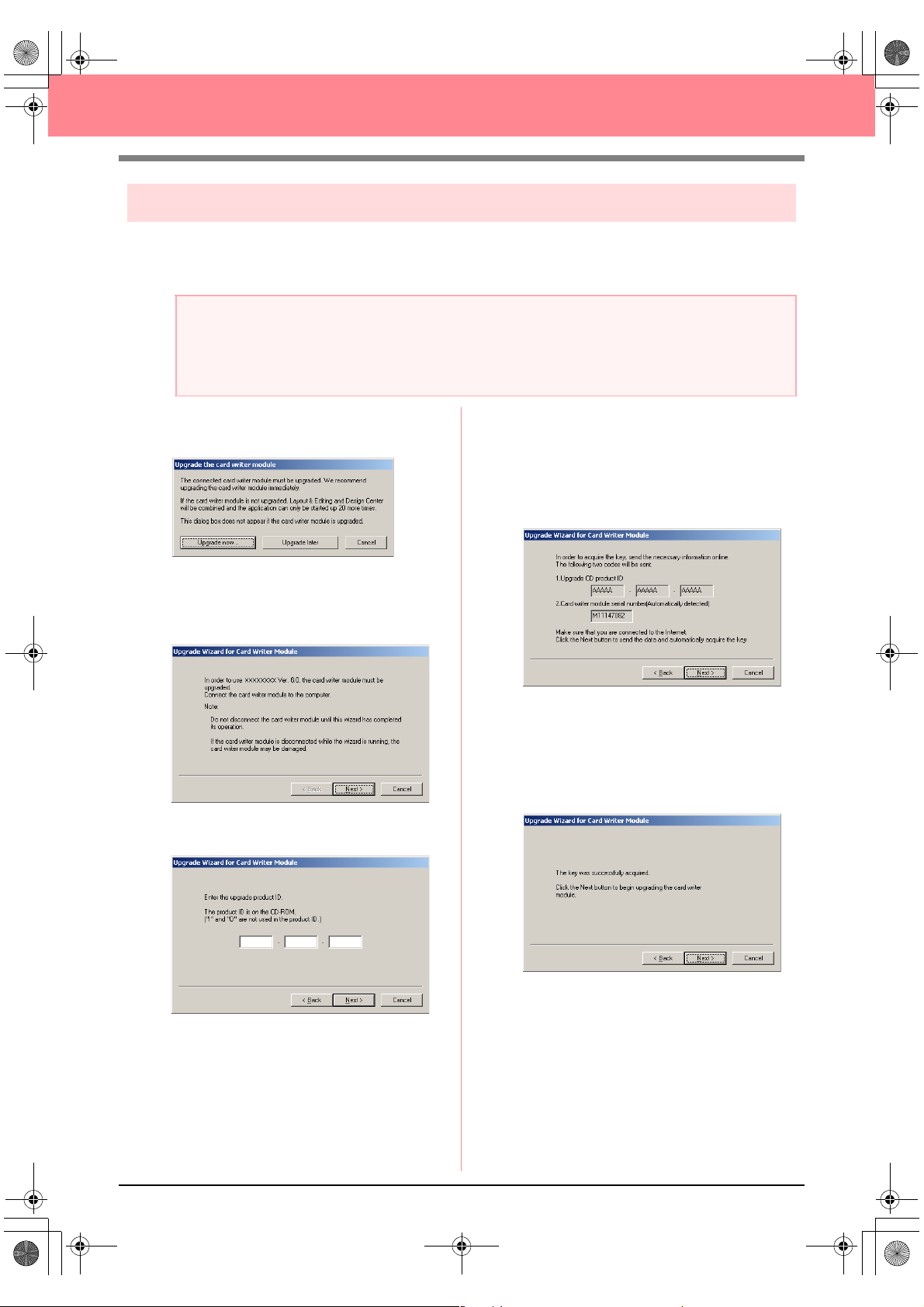
1. Start up Layout & Editing.
→ The dialog box shown below appears.
2. To begin the upgrade, click Upgrade now.
→ The Upgrade wizard starts up, and the
first dialog box shown below appears.
3. Click Next.
4. Type in the 15-digit product ID on the label
attached to the CD-ROM case, and then click
Next.
→ The entered product ID and the serial
number automatically retrieved from the
USB card writer module is displayed.
5. Click Next to access our server through the
Internet and retrieve the upgrade key.
→ If the upgrade key has been successfully
retrieved, the dialog box shown below appears.
12
6. Click Next to begin upgrading the USB card
writer module.
Page 21
BeforeUsing.fm Page 13 Thursday, July 8, 2004 2:57 PM
Before Use
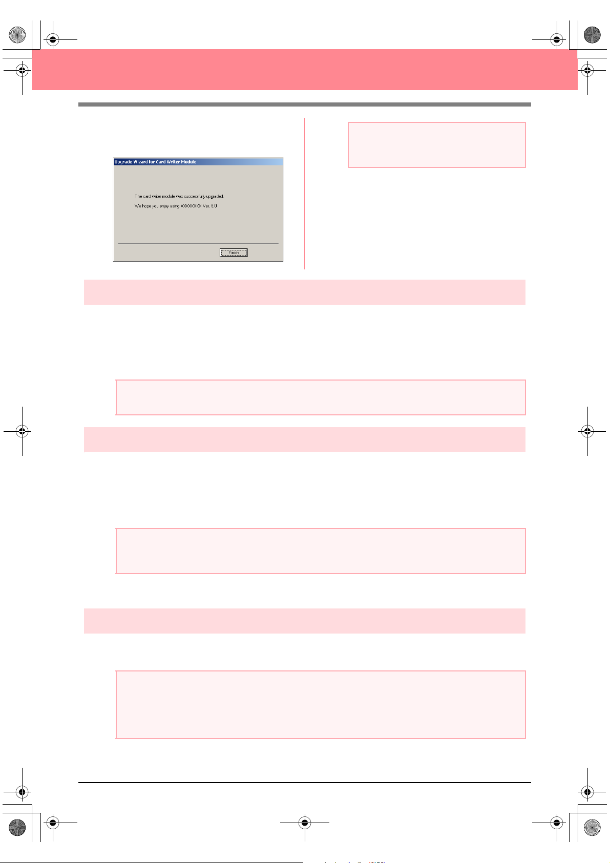
→ If the upgrade has been completed suc-
cessfully, the dialog box shown below appears.
a Note:
If a warning appears at any time, follow the
instructions that are displayed.
Online registration
If you wish to be contacted about upgrades and provided with important information such as future product
developments and improvements, you can register your product online by following a simple registration
procedure.
Click Online Registration on the Help menu of Layout & Editing to start up the installed Web browser and
open the online registration page on our Web site.
a Note:
Online registration may not be available in some areas.
Uninstallation
1. Turn on the computer and start up Windows.
2. Click the Start button in the task bar, and then click Control Panel.
3. In the Control Panel window, double-click Add or Remove Programs.
a Note:
With an operating system other than Windows XP, point to
Control Panel
. In the Control Panel window, double-click
4. In the dialog box that appeared, select this software, and then click Change/Remove.
Settings
Add/Remove Programs
in the
Start
menu, and then click
.
Technical support
Contact Technical Support if you have a problem. Please check the company web site (www.brother.com) to
find the Technical Support in your area.
a Note:
Have the following information ready before contacting Technical Support.
• The make and model of the computer that you are using as well as the Windows version (Refer to
page 8 and check the system requirements for this product again.)
• Information on any error messages that appear
13
Page 22
PeDesignV6Eng.book Page 14 Thursday, July 8, 2004 11:59 AM
Before Use
Tips and Techniques for Creating
Embroidery Patterns
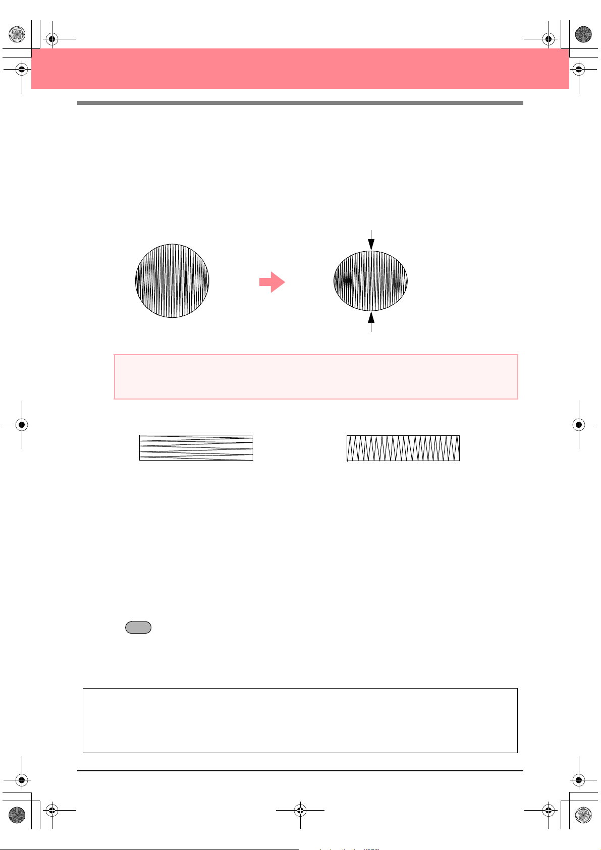
■ Sewing wide areas
When satin stitching is sewn in a wide area, the stitched area may shrink after sewing, depending on the
material and the type of thread used. If this happens, switch to this alternate method: Select the fill stitch and
use stabilizer material on the reverse side of the fabric.
Pattern
After sewing
a Note:
When using the satin stitch in a wide area, the needle may move out of position by about 10 mm with some
machines. In order to avoid this, use the above-mentioned alternate method.
■ Sewing direction
In order to limit shrinking, select a stitch direction perpendicular to the larger edge of the area.
Shrinking more likely to occur Shrinking less likely to occur
■ Sewing order
After creating an embroidery pattern made of several different parts (in Design Center or Layout & Editing), be
sure to check the sewing order and correct it if necessary.
With Design Center, the default sewing order is the order in which the sewing attributes are applied.
With Layout & Editing, the default sewing order is the order in which the elements are drawn.
■ Enlarging/reducing embroidery patterns
There are several ways of enlarging or reducing an imported embroidery pattern in Layout & Editing. You may
choose to scale your pattern with the pointer, or apply the Stitch to Block function, then scale the pattern.
When you normally scale an imported pattern, the number of stitches that will be sewn remains the same,
resulting in a change of embroidery quality if the size of the pattern is greatly changed. However, by holding
down the key while scaling the imported embroidery pattern, the original embroidery quality can be
maintained, since the stitch density and fill pattern automatically adapts to the new size.
Another method of maintaining the original embroidery quality of the pattern is to select the Sew – Stitch to
Block command, then scale the pattern. When a pattern is scaled only moderately, it may not be necessary
to apply the Stitch to Block function.
Ctrl
14
This system allows you to create a wide variety of embroidery patterns and supports wider ranges for the
setting of the sewing attributes (thread density, sewing pitch, etc.). However, the final result also depends
on your particular sewing machine model. We recommend that you make a trial sewing sample with your
sewing data before sewing on the final material. Remember to sew your trial sample on the same type of
fabric as your final material and to use the same needle and the same machine embroidery thread.
Page 23
PeDesignV6Eng.book Page 15 Thursday, July 8, 2004 11:59 AM
Before Use
Sew Types
The sewing attributes for each sew type are first set to their default settings; however, by changing the settings
of the sewing attributes, you can create custom stitching. (For details, refer to pages 91 through 95 and
pages 172 through 178.)
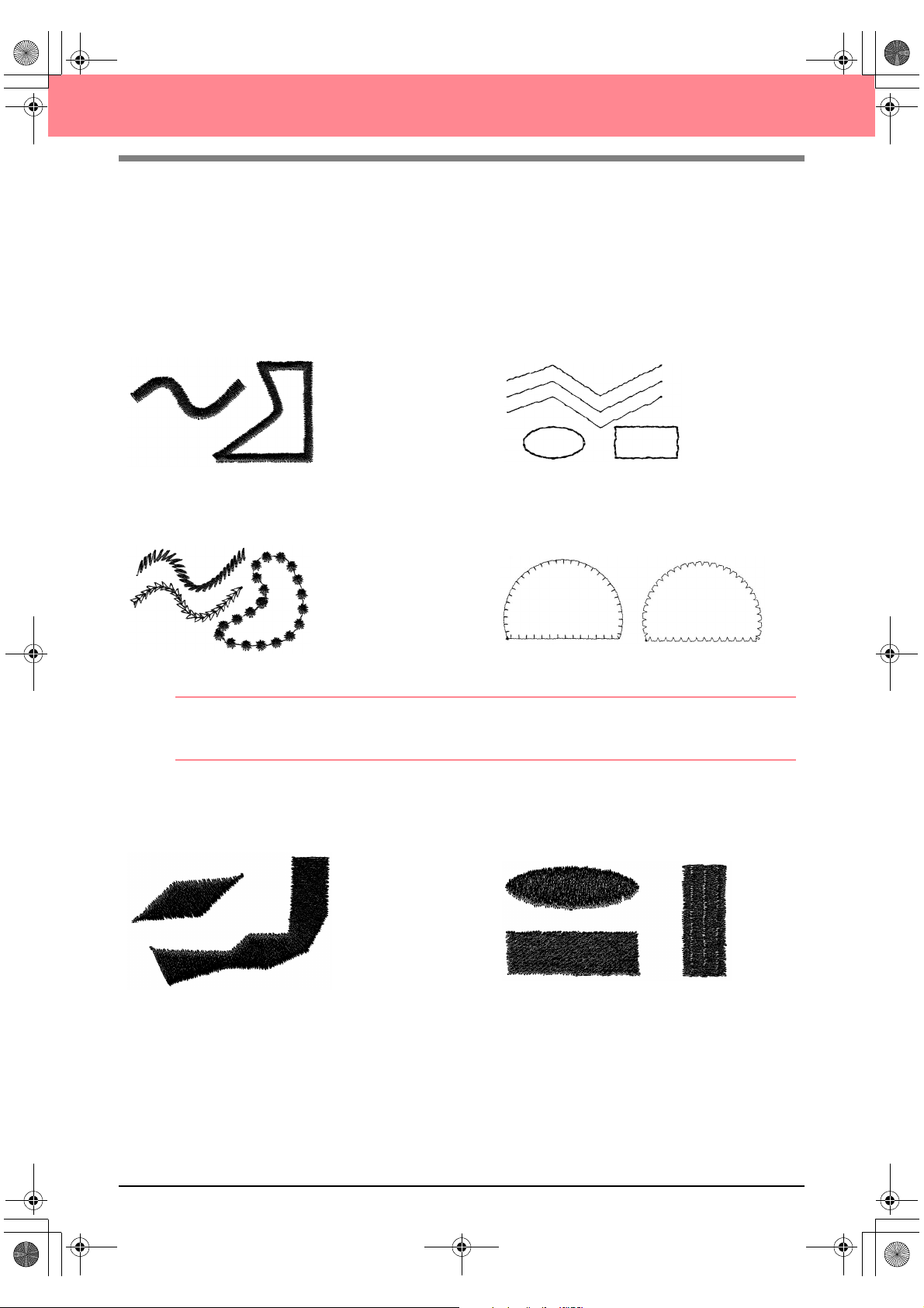
■ Line sew types
Zigzag stitch Running stitch
Motif stitch E/V stitch
b Memo:
The stitching for the programmable fill stitch and the motif stitch depends on the selected stitch pattern.
For details, refer to “Programmable fill stitch” on page 93 and 175 and “Motif stitch” on page 95 and 177.
■ Region sew types
Satin stitch Fill stitch
15
Page 24
PeDesignV6Eng.book Page 16 Thursday, July 8, 2004 11:59 AM
Before Use
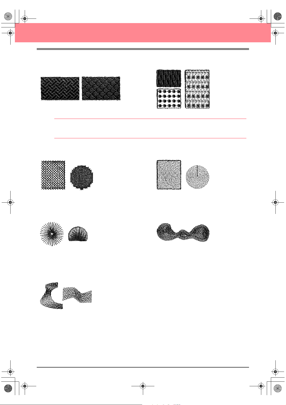
Programmable fill stitch Motif stitch
b Memo:
The stitching for the programmable fill stitch and the motif stitch depends on the selected stitch pattern.
For details, refer to “Programmable fill stitch” on page 93 and 175 and “Motif stitch” on page 95 and 177.
Cross stitch Concentric circle stitch
Radial stitch Spiral stitch
Piping stitch
16
Page 25
PeDesignV6Eng.book Page 17 Thursday, July 8, 2004 11:59 AM
Chapter 1
Basic Operation
17
Page 26
PeDesignV6Eng.book Page 18 Thursday, July 8, 2004 11:59 AM
Getting Started
About This Chapter
This chapter is organized as a tutorial to provide you with a hands-on introduction to the basic features of the
applications.
1. Automatically Creating Embroidery Patterns
1-1. Using the Auto Punch Function c page 19
In this section, we will use the Auto Punch function in Layout & Editing to automatically convert an
image to an embroidery pattern.
1-2. Using a Photo Stitch Function c page 25
In this section, we will use one of the Photo Stitch functions to create a more realistic embroidery
pattern from a image.
2. Creating and Editing Embroidery Patterns
2-1. Using Design Center c page 30
In this section, we will use Design Center to manually create an embroidery pattern from an image
using a four-stage procedure.
2-2. Using Layout & Editing c page 39
In this section, the embroidery pattern created in Design Center will be imported into Layout & Editing,
where a few objects will be added and the layout will be rearranged.
2-3. Using Programmable Stitch Creator c page 54
In this section, we will learn how to use Programmable Stitch Creator to edit a stitch in order to create
a custom stitch pattern.
3. Creating Large-Size Embroidery Patterns
3-1. Designing a large-size embroidery pattern c page 59
In this section, we will design an embroidery pattern that is too large to be sewn in a normal
embroidery hoop and therefore must be divided into sections.
3-2. Embroidering large-size embroidery patterns c page 63
In this section, we will sew the separate sections of the embroidery pattern to create large-size
embroidery.
18
Page 27
PeDesignV6Eng.book Page 19 Thursday, July 8, 2004 11:59 AM
Automatically Creating Embroidery Patterns
Using the Auto Punch Function
In this section, we are going to automatically create an embroidery pattern from an image.
Follow the instructions in this section step by step. If you have to interrupt this exercise for any reason, it is
recommended to save the file (refer to Step 6, “Saving the embroidery pattern”, on page 23). You will be able
to retrieve it later and resume your work.
The complete procedure will take you through the different steps of a normal working session using the Auto
Punch function.
Step 1 Starting up Layout & Editing page 19
Step 2 Opening an image file page 20
Step 3 Adjusting the size and position of the image page 21
Step 4 Automatically converting the image to an embroidery pattern page 21
Step 5 Displaying a preview of the embroidery pattern page 22
Step 6 Saving the embroidery pattern page 23
Step 7 Transferring the pattern to an original card page 24
Step 8 Quitting Layout & Editing page 24
Basic Operation
Step 1
Starting up Layout & Editing
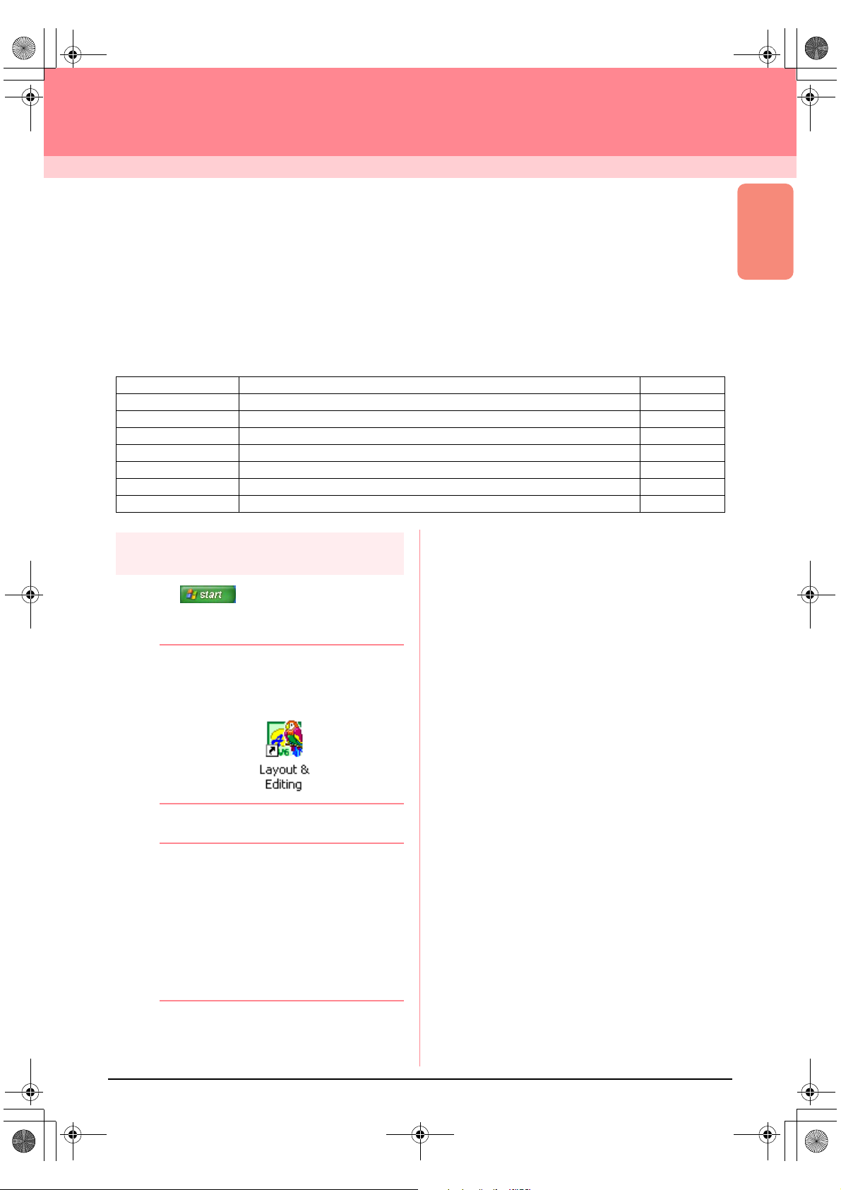
1. Click , select All Programs, then
PE-DESIGN Ver.6. Select Layout & Editing
to open the Layout & Editing window.
b Memo:
If a shortcut for Layout & Editing was
created, for example, on the desktop,
double-click it to start up the application.
→ The Layout & Editing window appears.
b Memo:
• To fill the entire screen with the Layout &
Editing window, click the maximize button
on the right end of the title bar.
• At this time, you can change the Design
Page properties by using the menu
command
Property
page 77.) For this example, we will not
change the Design Page settings.
Option – Design Page
. (For more details, refer to
19
Page 28
PeDesignV6Eng.book Page 20 Thursday, July 8, 2004 11:59 AM
Automatically Creating Embroidery Patterns
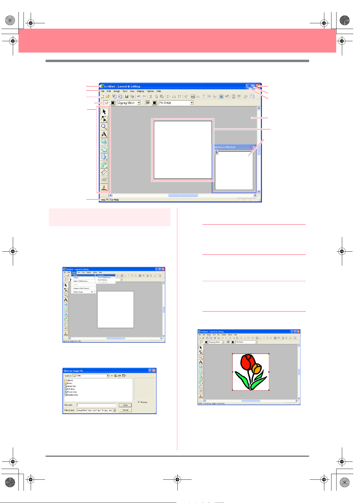
Title bar
Menu bar
Toolbar
Sewing Attributes bar
Too l Bo x
Status bar
Step 2
Opening an image file
First, we need to open the image that will be
converted into the embroidery pattern.
1. Click Image on the menu bar, point to Input,
and then click from File on the submenu.
Close button
Maximize button
Minimize button
Work area
Design Page
Reference Window
3. Select the sample file tulip.bmp in the ClipArt
folder.
b Memo:
If the
Preview
contents of the selected file will appear in the
Preview
4. Click Open to open the image file and to close
the dialog box.
check box is selected, the
box.
→ An Open an image file dialog box similar
to the one shown below appears.
2. Double-click the ClipArt folder to open it.
20
b Memo:
Double-clicking the file name also adds the
image to the work area and closes the dialog
box.
→ The image appears in the work area.
Page 29
PeDesignV6Eng.book Page 21 Thursday, July 8, 2004 11:59 AM
Automatically Creating Embroidery Patterns
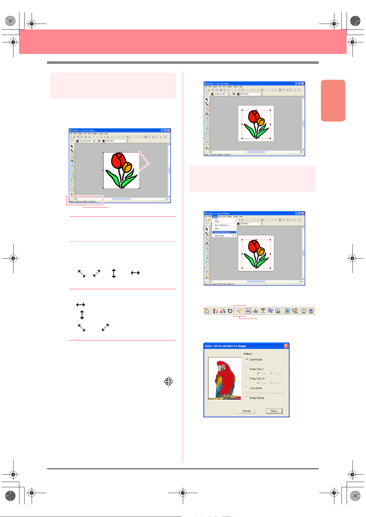
Step 3
Adjusting the size and position
of the image
1. Click Image on the menu bar, and then click
Modify.
→ Handles appear around the image.
Handles
Status bar
b Memo:
The status bar shows the dimensions (width
and height) of the image.
5. Drag the image to the desired location.
Basic Operation
Step 4
Automatically converting the
image to an embroidery pattern
1. Click Image on the menu bar, and then click
Image to Stitch Wizard.
2. Move the pointer over a handle.
→ The shape of the pointer changes to
, , , or , depending
on the handle that the pointer is over.
b Memo:
• is for scaling the width.
• is for scaling the height.
• and are for scaling both
dimensions at the same time.
3. Drag the handle to adjust the selected image
to the desired size.
4. Move the pointer over the selected image.
→ The shape of the pointer changes to .
An alternate method is to click the Toolbar
button indicated below.
Image to Stitch Wizard
→ The Select Stitch Method for Image dia-
log box appears.
2. Select Auto Punch, and then click Next.
→ The image is analyzed, and the resulting
image is displayed in the Image Analysis
dialog box.
21
Page 30
PeDesignV6Eng.book Page 22 Thursday, July 8, 2004 11:59 AM
Automatically Creating Embroidery Patterns
b Memo:
The following stitch methods are also
available.
Photo Stitch 1 (Color
•
Refer to page 116 for more details on the
Color
setting and to page 120 for more
details on the
Photo Stitch 2 (Color
•
Refer to page 122 for more details on the
Color
setting and to page 124 for more
details on the
•
Cross Stitch
For more details, refer to page 125.
•
Design Center
For more details, refer to “Using Design
Center” on page 30.
Mono
Mono
and
setting.
and
setting.
Mono
Mono
)
)
→ The image is converted to an embroidery
pattern, which is displayed in the Design
Page.
Step 5
Displaying a preview of the
embroidery pattern
You can display a preview of the embroidery
pattern in order to see how the stitching is
connected, or you can display a realistic preview
of the embroidery pattern in order to see how the
pattern will appear once it is sewn.
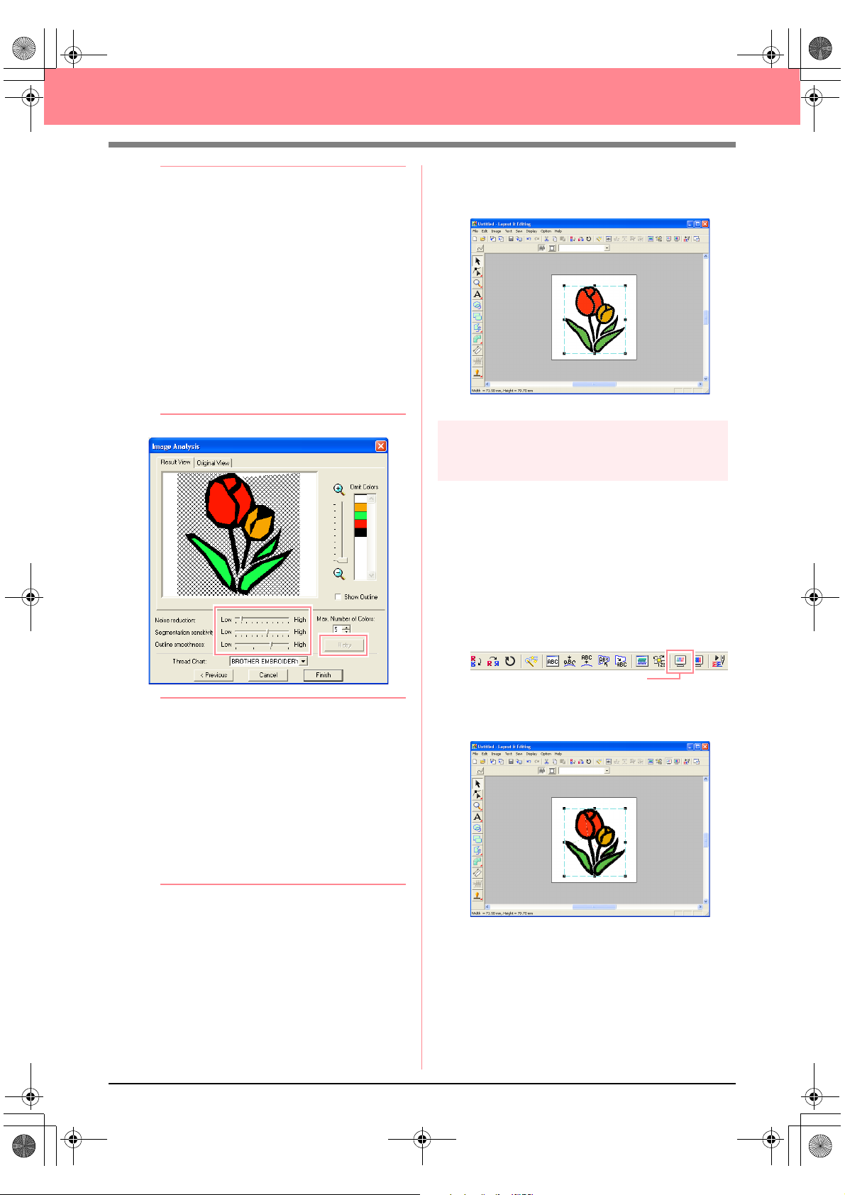
b Memo:
• Various settings are available for
converting the image to an embroidery
pattern. (For more details on the various
settings, refer to page 115.) After changing
the settings, click
image with the new settings applied.
• Areas of the image that will not be
converted to the embroidery pattern
appear with a crosshatch pattern. Click
each area to select whether or not it should
be converted.
3. Click Finish.
Retry
to display the
1. Click Display on the menu bar, and then click
Preview.
An alternate method is to click the Toolbar
button indicated below.
Preview
→ A preview of the embroidery pattern ap-
pears.
22
Page 31

PeDesignV6Eng.book Page 23 Thursday, July 8, 2004 11:59 AM
Automatically Creating Embroidery Patterns
b Memo:
• To zoom in (or out), click (or ) on
the Tool Box, and then click the desired
area of the embroidery pattern.
• To display, hide, or display a faded copy of
the original image, which remains in the
work area, click
point to
Display Image
desired display setting.
• To display the original image, click
On
.
• To display a faded copy of the image,
click
• To hide the original image, click
2. To display a realistic preview of the entire
embroidery pattern, click Display on the menu
bar, and then click Realistic Preview.
An alternate method is to click the Toolbar
button indicated below.
→ A realistic preview of the embroidery pat-
tern appears.
Image
Faded
.
Realistic Preview
on the menu bar,
, and then click the
Off
Step 6
Saving the embroidery pattern
Once the embroidery pattern is finished, you may
want to save it in order to retrieve it later.
1. Click File on the menu bar, and then click
Save.
An alternate method is to click the Toolbar
button indicated below.
Save
.
→ If the pattern has already been saved at
least once, the file is saved immediately.
Basic Operation
b Memo:
To save the file with a different name, use the
menu command
→ If no file name has been specified or if the
file cannot be found, the Save As dialog
box appears.
File
–
Save As
instead.
b Memo:
To zoom in (or out), click (or ) on the
Tool Box, and then click the desired area of
the embroidery pattern.
a Note:
The embroidery pattern cannot be edited
while the realistic preview is displayed.
3. To leave the realistic preview display, repeat
2., or press the key.
step
Esc
2. Select the drive and the folder, and then type
in the file name.
3. Click Save to save the pattern.
b Memo:
• To quit the operation, click
• If a file already exists with the name
specified in the
following message appears.
• To overwrite the file, click
new file name appears in the title bar
of the Layout & Editing window.
• If you do not want to overwrite the
existing file, click
enter a different file name.
Save As
Cancel
dialog box, the
Yes
No
. You can then
.
. The
23
Page 32

PeDesignV6Eng.book Page 24 Thursday, July 8, 2004 11:59 AM
Automatically Creating Embroidery Patterns
Step 7
Transferring the pattern to an
original card
Before you can actually sew the embroidery
pattern, you must transfer the pattern to a sewing
machine. Transfer the embroidery pattern to the
sewing machine using media of the type used by
your machine, for example, original cards, floppy
disks, CompactFlash cards, or USB media. For
this example, we will transfer the pattern to an
original card.
1. Insert an original card into the USB card writer
module.
a Note:
The original card is inserted correctly when
you hear it snap into place.
2. Click File on the menu bar, point to Write to
Card, and then click Current Design on the
submenu.
An alternate method is to click the Toolbar
button indicated below.
3. Click OK.
→ The following message appears.
b Memo:
To quit the operation, click
Cancel
a Note:
If the card writer module is not correctly
connected or powered, or if the original card
is not inserted or is defective, an error
message will appear. For more details, refer
to “Writing an embroidery pattern to an
original card” on page 195.
4. Click OK to close the message.
Step 8
Quitting Layout & Editing
.
Write to Card
→ The following message appears.
a Note:
If the original card is not brand new, make
sure that the patterns already stored on the
card are no longer needed.
1. Click File on the menu bar, and then click Exit.
→ The Layout & Editing window closes.
b Memo:
Layout & Editing can also be closed by
clicking the close button on the right end of
the title bar.
24
Page 33

PeDesignV6Eng.book Page 25 Thursday, July 8, 2004 11:59 AM
Automatically Creating Embroidery Patterns
Using a Photo Stitch Function
In this section, we are going to automatically create a more realistic embroidery pattern from a photo.
Follow the instructions in this section step by step. If you have to interrupt this exercise for any reason, it is
recommended to save the file (refer to Step 6, “Saving the embroidery pattern”, on page 23). You will be able
to retrieve it later and resume your work.
The complete procedure will take you through the different steps of a normal working session using one of the
Photo Stitch functions.
Step 1 Starting up Layout & Editing page 25
Step 2 Opening an image file page 26
Step 3 Adjusting the size and position of the image page 27
Step 4 Automatically converting the image to an embroidery pattern page 27
Step 1
Starting up Layout & Editing
1. Click , select All Programs, then
PE-DESIGN Ver. 6. Select Layout & Editing
to open the Layout & Editing window.
Basic Operation
b Memo:
If a shortcut for Layout & Editing was
created, for example, on the desktop,
double-click it to start up the application.
→ The Layout & Editing window appears.
b Memo:
• To fill the entire screen with the Layout &
Editing window, click the maximize button
on the right end of the title bar.
• At this time, you can change the Design
Page properties by using the menu
command
Property
page 77.) For this example, we will not
change the Design Page settings.
Option – Design Page
. (For more details, refer to
25
Page 34
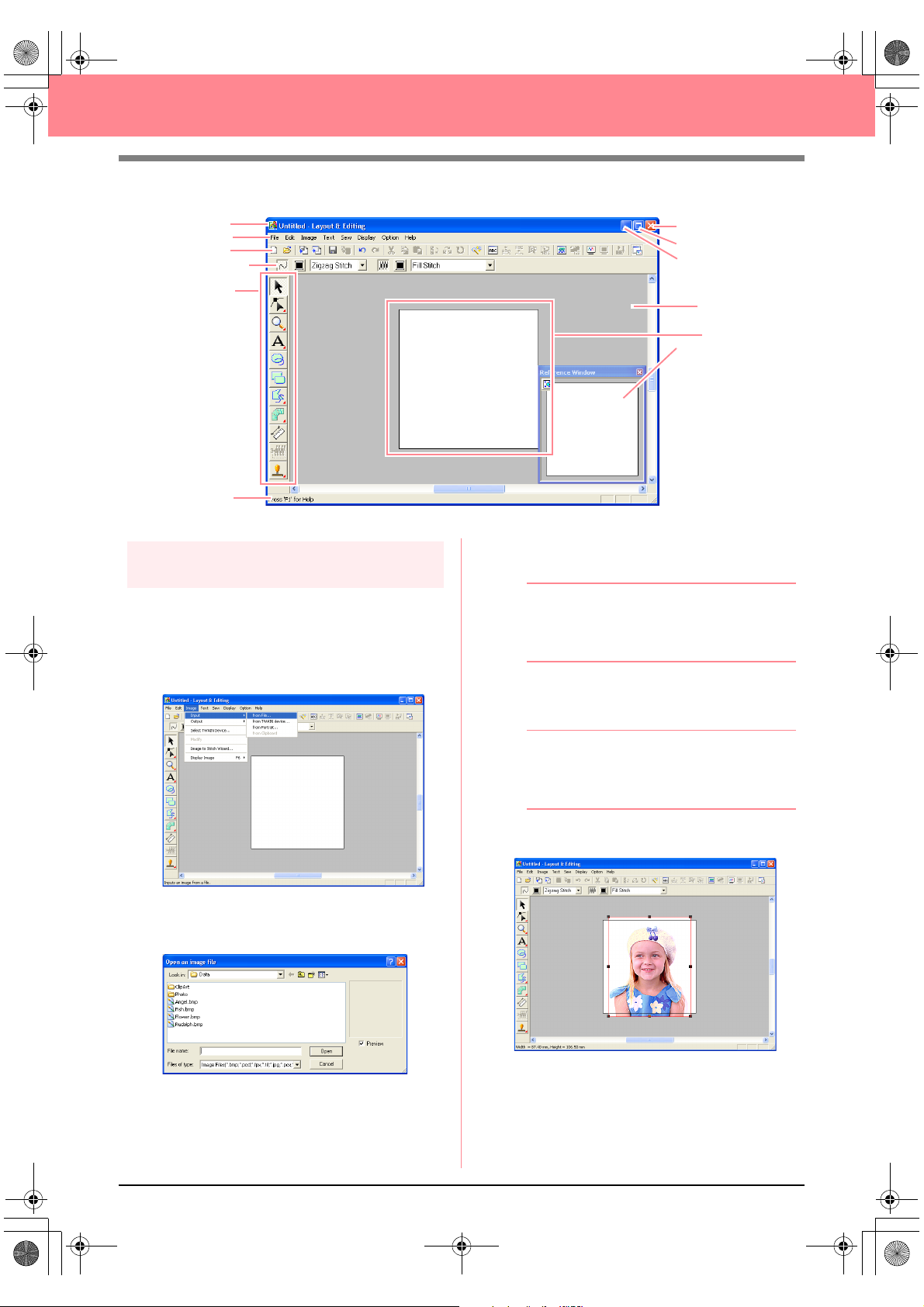
PeDesignV6Eng.book Page 26 Thursday, July 8, 2004 11:59 AM
Automatically Creating Embroidery Patterns
Title bar
Menu bar
Toolbar
Sewing Attributes bar
Too l Bo x
Status bar
Step 2
Opening an image file
First, we need to open the image that will be
converted into an embroidery pattern.
1. Click Image on the menu bar, point to Input,
and then click from File on the submenu.
Close button
Maximize button
Minimize button
Work area
Design Page
Reference Window
3. Select the sample file girl.bmp in the Photo
folder.
b Memo:
If the
Preview
contents of the selected file will appear in the
Preview
4. Click Open to open the image file and to close
the dialog box.
check box is selected, the
box.
→ The Open an image file dialog box ap-
pears.
2. Double-click the Photo folder to open it.
26
b Memo:
Double-clicking the file name also adds the
image to the work area and closes the dialog
box.
→ The image appears in the work area.
Page 35
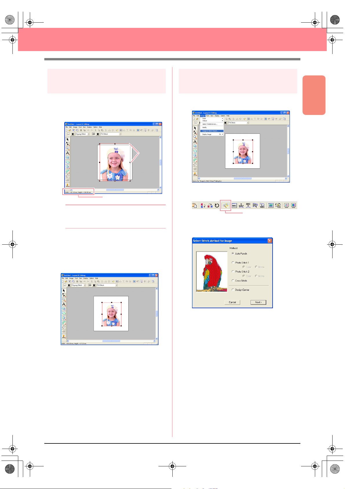
PeDesignV6Eng.book Page 27 Thursday, July 8, 2004 11:59 AM
Automatically Creating Embroidery Patterns
Step 3
Adjusting the size and position
of the image
1. Click Image on the menu bar, and then click
Modify.
→ Handles appear around the image.
Handles
Status bar
b Memo:
The status bar shows the dimensions (width
and height) of the image.
2. Adjust the selected image to the desired size,
and move it to the desired location.
For more details, refer to , “Changing the
c
Size and Position of the Image”, on page
114.
Step 4
Automatically converting the
image to an embroidery pattern
1. Click Image on the menu bar, and then click
Image to Stitch Wizard.
An alternate method is to click the Toolbar
button indicated below.
Image to Stitch Wizard
→ The Select Stitch Method for Image dia-
log box appears.
Basic Operation
27
Page 36

PeDesignV6Eng.book Page 28 Thursday, July 8, 2004 11:59 AM
Automatically Creating Embroidery Patterns
2. Select Photo Stitch 1, then Color, and then
click Next.
→ The Select Mask dialog box appears.
b Memo:
The following stitch methods are also
available.
Auto Punch
•
For more details, refer to page 115.
•
Photo Stitch 1 (Mono
For more details on the
to page 120.
Photo Stitch 2 (Color
•
Refer to page 122 for more details on the
Color
setting and to page 124 for more
details on the
•
Cross Stitch
For more details, refer to page 125.
•
Design Center
For more details, refer to “Using Design
Center” on page 30.
Mono
)
Mono
and
setting.
setting, refer
Mono
)
4. In the image preview box, move the handles of
the mask until it surrounds the desired part of
the image to be converted to an embroidery
pattern.
b Memo:
Any part of the image that is outside of the
mask will not be converted to an embroidery
pattern.
5. Click Next.
→ The image is analyzed, and the Check
Mask Shape dialog box appears.
3. From the list at the bottom of the dialog box,
select the desired shape that the image will be
trimmed to.
28
Page 37

PeDesignV6Eng.book Page 29 Thursday, July 8, 2004 11:59 AM
Automatically Creating Embroidery Patterns
6. If the shape and position of the mask are as
desired, click Next.
→ The Photo Stitch 1 Parameters dialog
box appears.
b Memo:
Various settings are available for converting
the image to an embroidery pattern. (For
more details on the various settings, refer to
page 116.)
8. Click Finish.
→ The embroidery pattern is displayed in the
Design Page.
For details on previewing the embroidery
c
pattern, refer to Step 5, “Displaying a
preview of the embroidery pattern”, on
page 22.
For details on saving the embroidery
c
pattern as a file, refer to Step 6, “Saving
the embroidery pattern”, on page 23.
For details on transferring the embroidery
c
pattern to an original card, refer to Step 7,
“Transferring the pattern to an original
card”, on page 24.
Basic Operation
7. Click Next.
→ The image is converted to an embroidery
pattern, which is displayed in the Preview
dialog box.
29
Page 38

PeDesignV6Eng.book Page 30 Thursday, July 8, 2004 11:59 AM
Creating and Editing Embroidery Patterns
Using Design Center
In this section, we are going to manually create an embroidery pattern from an image using a four-stage
procedure. This pattern will be used later as the stepping stone to create a more complex embroidery pattern.
Follow the instructions in this section step by step. If you have to interrupt this exercise for any reason, it is
recommended to save the file (refer to Step 9, “Saving the file”, on page 38). You will be able to retrieve it later
and resume your work.
The complete procedure will take you through the different steps of a normal working session with Design
Center and will introduce you to its most important features.
Step 1 Starting up Design Center page 30
Step 2 Opening an image file page 31
Step 3 Continuing to stage 2 (Line Image stage) page 31
Step 4 Editing lines page 32
Step 5 Continuing to stage 3 (Figure Handle stage) page 33
Step 6 Continuing to stage 4 (Sew Setting stage) page 34
Step 7 Specifying sewing attributes page 34
Step 8 Previewing the image page 37
Step 9 Saving the file page 38
Step 1
Starting up Design Center
1. Click , select All Programs, then
PE-DESIGN Ver.6. Select Design Center to
open the Design Center window.
b Memo:
If a shortcut for Design Center was created,
for example, on the desktop, double-click it to
start up the application.
→ The How do you want to produce em-
broidery? dialog box and the Design
Center window appear.
b Memo:
To fill the entire screen with the Design
Center window, click the maximize button on
the right end of the title bar.
30
Page 39

PeDesignV6Eng.book Page 31 Thursday, July 8, 2004 11:59 AM
Creating and Editing Embroidery Patterns
Step 2
Opening an image file
First, we need to open the image that will be used
to create the embroidery pattern.
1. In the How do you want to produce
embroidery? dialog box, click .
→ The From Image dialog box appears.
2. Click .
→ The Open dialog box appears.
4. Click Open to open the image file and to close
the dialog box.
b Memo:
Double-clicking the file name also adds the
image to the work area and closes the dialog
box.
→ The image appears in the Design Page
and in the Cut out to Line Image dialog
box.
Step 3
Continuing to stage 2 (Line
Image stage)
Basic Operation
b Memo:
The
Open
by selecting the menu command
dialog box can also be displayed
in Design Center.
Open
–
File
3. Select the sample file Flower.bmp in the Data
folder.
b Memo:
If the
Preview
contents of the selected file will appear in the
Preview
check box is selected, the
box.
After opening the image, we will continue to stage
2 (Line Image stage), where we will select the
color(s) that will be used to create the line image
(outline of the image).
b Memo:
If the wizard is not being used, click
the menu bar, and then click
An alternate method is to click the Toolbar
button indicated below.
1. Move the pointer over the image in the Cut
out to Line Image dialog box.
→ The shape of the pointer changes to .
b Memo:
To display the image enlarged (or reduced),
move the
the image is enlarged, you can scroll through
it to display different parts.
ZOOM
slider up (or down). When
Stage
on
To Line Image
To Line Image
.
31
Page 40
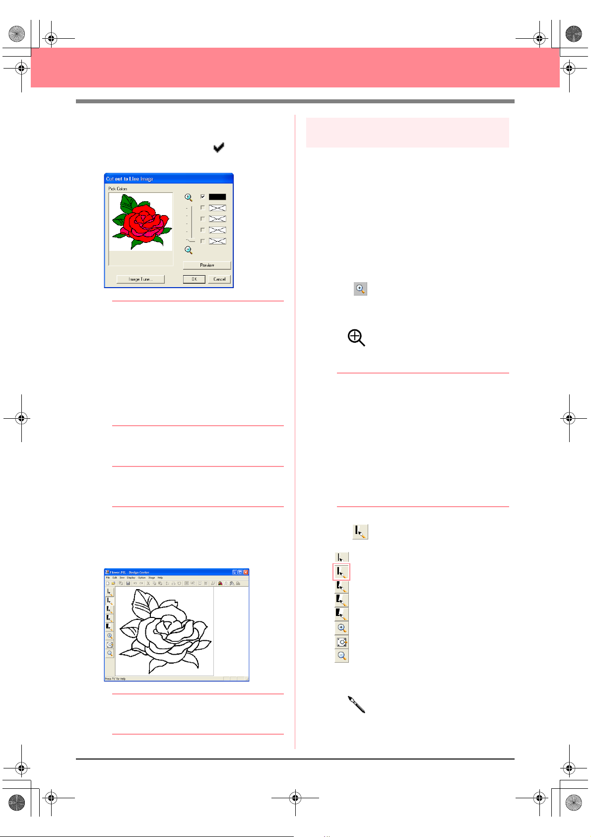
PeDesignV6Eng.book Page 32 Thursday, July 8, 2004 11:59 AM
Creating and Editing Embroidery Patterns
2. Click any part of the outline.
→
The selected color appears in the top box
Pick Colors
under
check box to show that the color is selected.
, and appears in the
b Memo:
• If the image contains outlines of different
colors, you can repeat step
to five colors. If more than five colors are
selected, only the last five colors selected
remain in the list.
• To deselect a color, clear the
corresponding check box.
• To adjust the color tone and reduce image
noise (distortions), click
more details, refer to page 74.)
2.
to select u p
Image Tune
. (For
3. Click Preview to preview the line image in the
Design Page.
b Memo:
To quit the operation and go back to stage 1
(Original Image stage), click
Cancel
.
Step 4
Editing lines
At this time, you might need to correct a few lines
in the line image. You should make sure that
regions are completely enclosed by either a single
closed line or intersecting lines. You may also
want to edit the line image and either add or
remove some details. You can do this at this time
using the pens and erasers in the Tool Box.
In this example, we are going to display the line
image enlarged to make editing easier, then use
an eraser to remove some of the outline.
1. Click .
→ When the pointer is moved over the work
area, the shape of the pointer changes to
.
2. Click the line image.
b Memo:
• To further enlarge the line image, repeat
step
2.
• To zoom in on a specific area, move the
pointer near the desired area, and then
drag the pointer diagonally over the
desired area. A dotted box appears as you
drag the pointer, and the selected area is
enlarged when the mouse button is
released.
Zoom
For more details on the
the Tool Box, refer to page 234.
buttons in
4. When the line image appears as desired, click
OK.
→ The line image is displayed in the Design
Page.
b Memo:
At this time, the pattern can be saved as a .pel file. For
details, refer to Step 9, “Saving the file”, on page 38.
32
3. Click on the Tool Box.
→ When the pointer is moved over the work
area, the shape of the pointer changes to
.
Page 41

PeDesignV6Eng.book Page 33 Thursday, July 8, 2004 11:59 AM
Creating and Editing Embroidery Patterns
4. Move the pointer over the line that you want to
erase, and then hold down the right mouse
button.
→ The shape of the pointer changes to
.
5. Carefully drag the pointer to erase the line.
6. Repeat steps 4. and 5. to delete a few
leaves.
b Memo:
• If you deleted part of the outline by
mistake, you may need to redraw some of
lines. To do this, simply hold down the left
mouse button and start drawing the line.
• If you are not satisfied with your editing,
Stage
–
select the menu command
Original Image
(Original Image stage), and then create
the line image and start editing again.
to go back to stage 1
To
b Memo:
To select how the reduced line image is
displayed:
1) Click on the Tool Box.
→
When the pointer is moved over the
work area, the shape of the pointer
changes to .
2) Click the Design Page.
3) To further reduce the line image, repeat
step 2).
Step 5
Continuing to stage 3 (Figure
Handle stage)
In stage 2 (Line Image stage), the line image is
simply a collection of dots (or pixels). Editing in
stage 2 means adding or removing black dots.
When you move to stage 3 (Figure Handle stage),
the application automatically connects the dots to
create lines, which can be edited.
1. Click Stage on the menu bar, and then click
To Figure Handle.
An alternate method is to click the Toolbar
button indicated below.
To Figure Handle
→ The Figure Object Conversion Setting
dialog box appears.
Basic Operation
7. After editing the line image, click on the
Tool Box to view the entire line image so that
it fits in the window.
→ The Design Page fills the Design Center
window.
33
Page 42
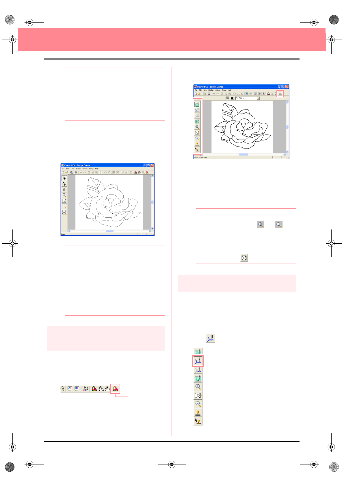
PeDesignV6Eng.book Page 34 Thursday, July 8, 2004 11:59 AM
Creating and Editing Embroidery Patterns
b Memo:
Various settings are available for converting
the line image to a figure handle image. (For
more details on the various settings, refer to
page 76.) In addition, this dialog box allows
you to preview how the image will fit in the
selected Design Page (the size of the area to
be sewn).
2. Click OK.
→ The line image is converted to a figure
handle image, which is displayed in the
Design Page.
b Memo:
• The Tool Box for stage 3 (Figure Handle
stage) contains various editing tools for
drawing lines, moving, deleting or inserting
points as well as zooming. For details on
the editing tools, refer to page 234.
• At this time, you can change the Design
Page properties by using the menu
command
Property
page 77.)
Step 6
Continuing to stage 4 (Sew
Setting stage)
Option – Design Page
. (For more details, refer to
→ The Tool Box for stage 4 (Sew Setting
stage) appears.
In this stage, you can set and check the
sewing attributes for each part of the pattern.
You can also specify hole sewing for larger
regions that completely enclose smaller ones
in order to avoid sewing the same region
twice. Other tools are available for zooming.
b Memo:
• To zoom in (or out), click (or ) on
the Tool Box, and then click the desired
area of the embroidery pattern, as in stage
3 (Figure Handle stage).
• To display the Design Page so that it fits
the window, click on the Tool Box.
Step 7
Specifying sewing attributes
We are now going to apply sewing attributes to
the different parts of the pattern.
■ Specifying sewing attributes for
the outline
1. Click on the Tool Box.
1. Click Stage on the menu bar, and then click
To Sew Setting.
An alternate method is to click the Toolbar
button indicated below.
34
To Sew Setting
Page 43

PeDesignV6Eng.book Page 35 Thursday, July 8, 2004 11:59 AM
Creating and Editing Embroidery Patterns
→ The shape of the pointer changes to
, and the Sewing Attributes bar ap-
pears as shown below.
2. To change the outline color, click the Line
color button ( ) on the Sewing Attributes
bar, click the desired color in the Line Thread
Color dialog box that appeared, and then click
Close.
b Memo:
To move the dialog box to a more convenient
place on the screen, move the pointer over
the title bar, and then drag the dialog box.
→ The Sewing Attribute Setting dialog box
appears, containing the default settings
for the selected outline sew type.
5. To change the width from 2.0 mm to 1.5 mm,
move the slider to the left until Zigzag width is
set to 1.5.
b Memo:
To close the dialog box, click
6. Click the outline of the pattern to apply the
attributes (color, sew type and width) to it.
→ The image now appears as shown below
with “marching lines” along the outline.
Close
.
Basic Operation
→ The Line color button ( ) on the Sew-
ing Attributes bar is displayed in the selected color.
3. To change the sew type to the zigzag stitch,
click in the Line sew type selector
( ) on the Sewing Attributes bar,
and then click Zigzag Stitch.
4. To change the attributes for the zigzag stitch,
click Sew on the menu bar, and then click
Sewing Attribute.
An alternate method is to click the Toolbar
button indicated below.
Sewing Attribute
b Memo:
If you think that the width of the outline is too
thick, you can change it again. To change the
width of the outline, repeat step 5., and then
click the outline to apply the new setting. (If
Sewing Attribute Setting
the
not displayed, right-click the outline.)
dialog box is
35
Page 44

PeDesignV6Eng.book Page 36 Thursday, July 8, 2004 11:59 AM
Creating and Editing Embroidery Patterns
■ Specifying sewing attributes for
the regions
1. Click on the Tool Box.
→ The shape of the pointer changes to
, and the Sewing Attributes bar ap-
pears as shown below.
For the leaves
2. Click the Region color button ( ) on the
Sewing Attributes bar, click the color LEAF
GREEN in the Region Thread Color dialog
box that appeared, and then click Close.
→ The Region color button ( ) on the
Sewing Attributes bar is displayed in the
selected color.
3. Click in the Region sew type selector
( ) on the Sewing Attributes bar,
and then click Fill Stitch.
5. To change the direction of the fill stitching,
click Constant under Direction, move the
pointer over the red arrow inside of the circle
under Constant, and then drag the red arrow
to the desired angle.
b Memo:
• When the pointer is moved over the red
arrow, its shape changes to .
• Using different directions for different
regions can add contrast and improve the
Direction set to 45°
Direction set to 90°
appearance of the embroidery.
4. To change the attributes for the fill stitch, click
Sew on the menu bar, and then click Sewing
Attribute.
An alternate method is to click the Toolbar
button indicated below.
Sewing Attribute
→ The Sewing Attribute Setting dialog box
appears, containing the default settings
for the selected region sew type.
Direction set to 135°
6. Click the regions of the leaves to which you
want to apply the attributes.
→ “Marching lines” appear around the se-
lected region.
7. Repeat steps 5. and 6. until attributes are
applied to all leaves.
36
Page 45
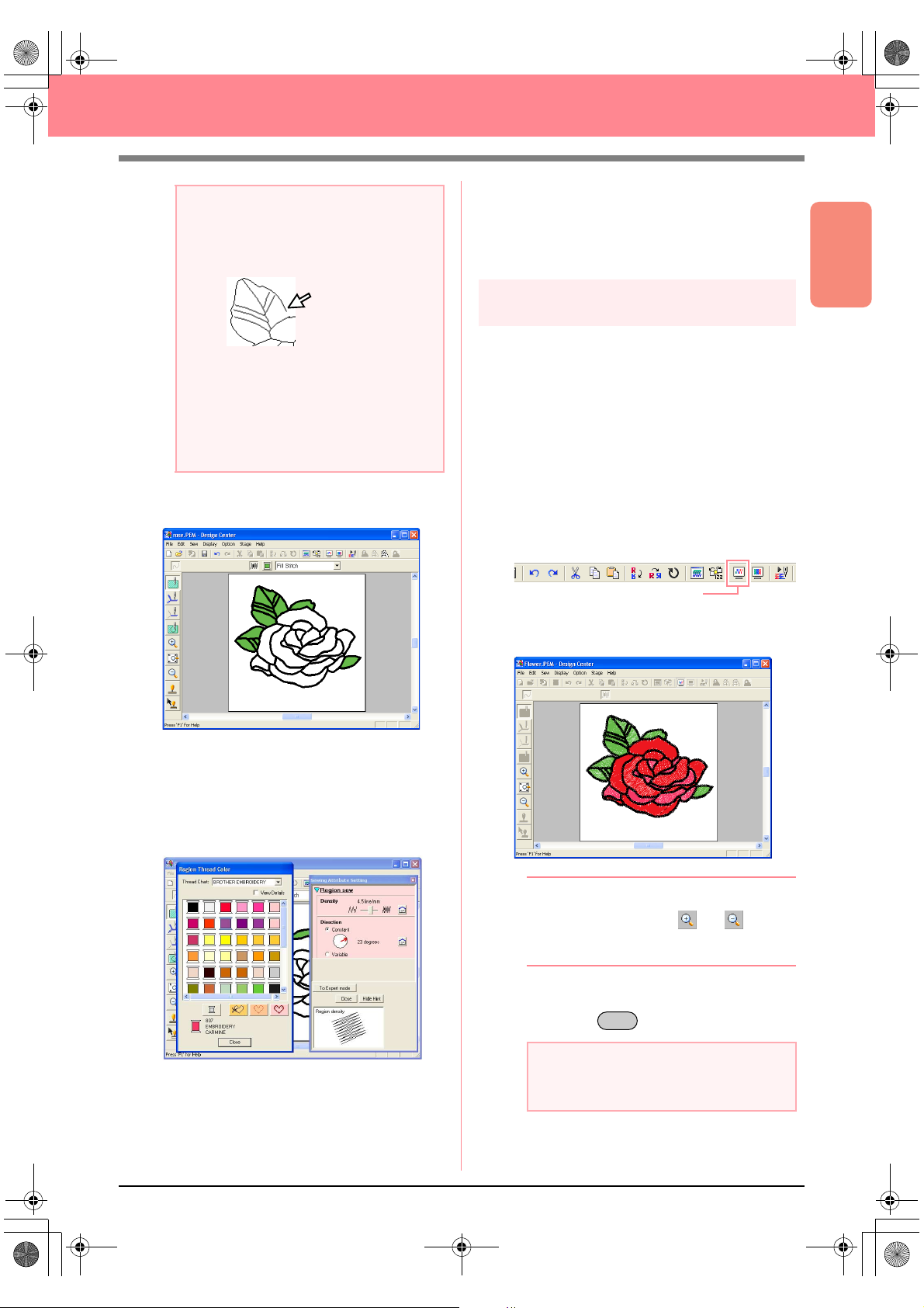
PeDesignV6Eng.book Page 37 Thursday, July 8, 2004 11:59 AM
Creating and Editing Embroidery Patterns
a Note:
Sewing attributes cannot be applied to
regions that are not fully enclosed, as shown
in the illustration of the leaf below.
For the other side of the petals
9. Select the color RED, set the stitching
direction, and then click each region where
you want to apply the attributes.
If the attributes cannot be applied to a
region, go back to stage 3 (Figure Handle
stage) and make sure that region is closed.
Edit any broken lines with the Point Edit tool.
For details on editing the figure handle
image, refer to “Editing Points in Outlines” on
page 81.
After applying the sewing attributes to the
leaves, the image appears as shown below.
Step 8
Previewing the image
You can display a preview of the embroidery
pattern in order to see how the stitching is
connected, or you can display a realistic preview
of the embroidery pattern in order to see how the
pattern will appear once it is sewn. (The
embroidery pattern can only be previewed in
stage 4 (Sew Setting stage) only.)
1. To display a preview of the embroidery
pattern, click Display on the menu bar, and
then click Preview.
An alternate method is to click the Toolbar
button indicated below.
Preview
→ A preview of the embroidery pattern ap-
pears.
Basic Operation
For one side of the petals
8. Select the color CARMINE, set the stitching
direction, and then click each region where
you want to apply the attributes.
b Memo:
To zoom in (or out), click (or ) on the
Tool Box, and then click the desired area of
the embroidery pattern.
2. To leave the preview display, repeat step 1.,
or press the key.
Esc
a Note:
The embroidery pattern cannot be edited
while the preview is displayed.
37
Page 46
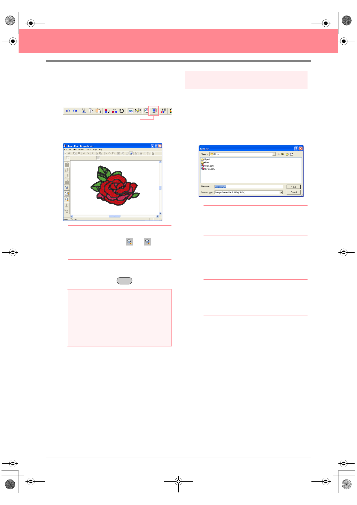
PeDesignV6Eng.book Page 38 Thursday, July 8, 2004 11:59 AM
Creating and Editing Embroidery Patterns
3. To display a realistic preview of the
embroidery pattern, click Display on the menu
bar, and then click Realistic Preview.
An alternate method is to click the Toolbar
button indicated below.
Realistic Preview
→ A realistic preview of the embroidery pat-
tern appears.
b Memo:
To zoom in (or out), click (or ) on the
Tool Box, and then click the desired area of
the embroidery pattern.
Step 9
Saving the file
Since this embroidery pattern will be used as the
basis of a more complex embroidery picture, we
need to save it.
1. Click File on the menu bar, and then click
Save As.
→ The Save As dialog box appears.
b Memo:
To overwrite the original file in the original
folder, use the menu command
instead.
2. The default name Flower.pem is displayed.
3. If necessary, change the drive and folder.
File
–
Save
4. To leave the realistic preview display, repeat
step
3., or press the key.
Esc
a Note:
• The embroidery pattern cannot be edited
while the realistic preview is displayed.
• The Realistic Preview function cannot
display a clean preview of the pattern if the
monitor is set to 256 colors or less. The
monitor should be set to at least 16-bit
High Color (65536 colors).
4. Click Save to save the file.
b Memo:
.pem files cannot be written to original cards.
Import them into Layout & Editing first. (For
details, refer to “Importing embroidery
patterns from Design Center” on page 128.)
38
Page 47
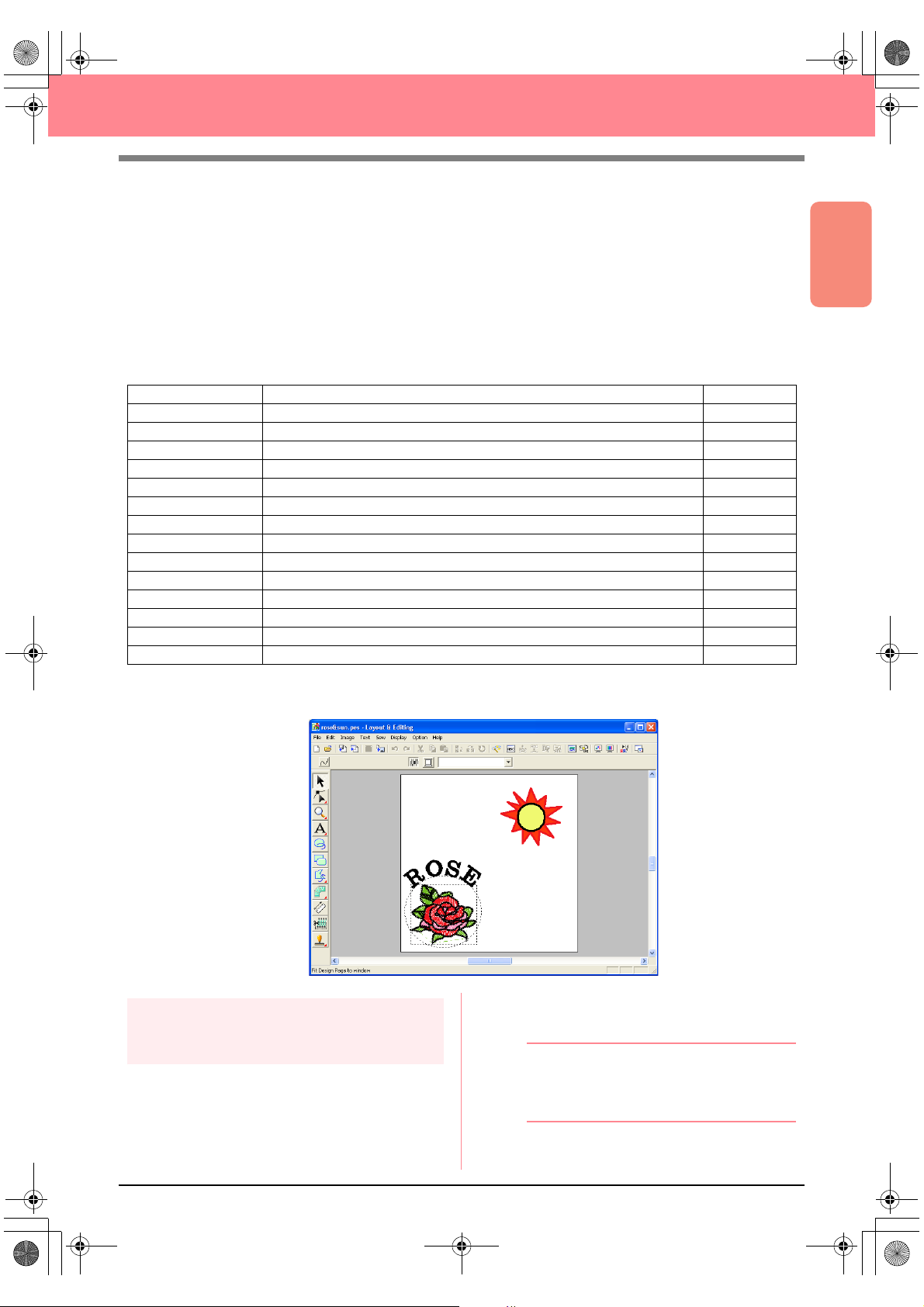
PeDesignV6Eng.book Page 39 Thursday, July 8, 2004 11:59 AM
Creating and Editing Embroidery Patterns
Using Layout & Editing
In this section, we are going to complete the embroidery pattern by combining a pattern imported from Design
Center with objects created using Layout & Editing, one of which will have a programmable fill stitch applied
to it.
Follow the instructions in this section step by step. If you have to interrupt this exercise for any reason, it is
recommended to save the file (refer to Step 14, “Saving the file”, on page 53). You will be able to retrieve it
later and resume your work.
The complete procedure will take you through the different steps of a normal working session with Layout &
Editing and will introduce you to some of its most important features.
Step 1 Importing embroidery patterns from Design Center page 39
Step 2 Adjusting the size and position of the embroidery pattern page 40
Step 3 Adding shapes page 41
Step 4 Adding text page 43
Step 5 Fitting the text around the oval page 44
Step 6 Adding a circle for the center of the sun page 45
Step 7 Selecting a programmable fill stitch page 46
Step 8 Adding a closed broken line for the sun’s rays page 48
Step 9 Changing the sewing order of sun and rays page 49
Step 10 Adjusting the rays page 50
Step 11 Setting hole sewing page 50
Step 12 Previewing the embroidery pattern page 51
Step 13 Transferring the pattern to an original card page 52
Step 14 Saving the file page 53
Step 15 Quitting Layout & Editing page 53
Basic Operation
At the end of this session, the embroidery pattern will appear as shown below.
Step 1
Layout & Editing, the .pem file must be opened in
Design Center.
Importing embroidery patterns
from Design Center
The first object of the embroidery pattern will be
the file Flower.pem, which we created in Design
Center. In order to import an embroidery pattern
from Design Center into the Design Page of
b Memo:
If Design Center has not been started up,
refer to “Starting up Design Center” on
page 30.
39
Page 48

PeDesignV6Eng.book Page 40 Thursday, July 8, 2004 11:59 AM
Creating and Editing Embroidery Patterns
1. In Design Center, click File on the menu bar,
and then click Open.
→ An Open dialog box similar to the one
shown below appears.
2. Select Design Center PEM File (*.PEM) in
the Files of type box, the sample file
Flower.pem in the Data folder, and then click
Open.
b Memo:
If the
Preview
contents of the selected file will appear in the
Preview
check box is selected, the
box.
a Note:
Be sure to select a .pem file saved in stage
4 (Sew Setting stage).
You cannot import another file type from
Design Center.
An alternate method is to click the Toolbar
button indicated below.
from Design Center
→ The Import size dialog box appears.
5. In the Magnification box, type or select 70%,
and then click Import.
→ The embroidery pattern is imported into
the Design Page of Layout & Editing.
Handles
→ The embroidery pattern is displayed in the
Design Page of Design Center.
3. Click Option on the menu bar, and then click
Layout & Editing to display the Layout &
Editing window.
4. In Layout & Editing, click File on the menu bar,
point to Import, and then click from Design
Center on the submenu.
b Memo:
• The dotted line and the handles that
appear around the embroidery pattern
show that the pattern is selected.
• The status bar shows the dimensions
(width and height) of the selected pattern.
Step 2
Adjusting the size and position
of the embroidery pattern
When you import a pattern from Design Center,
Layout & Editing puts the pattern at the center of
the Design Page. We are now going to change the
size of the imported pattern and move it to a
different location.
1. Click on the Tool Box.
→ The shape of the pointer changes to
.
40
Page 49

Basic_01.fm Page 41 Friday, July 9, 2004 1:43 PM
Creating and Editing Embroidery Patterns
2. Move the pointer over a handle.
→ The shape of the pointer changes to
, , , or , depending
on the handle that the pointer is over.
b Memo:
• is for scaling the width.
• is for scaling the height.
• and are for scaling both
dimensions at the same time.
3. Drag the handle to adjust the selected pattern
to the desired size.
b Memo:
To maintain the stitch density and fill pattern,
hold down the key while dragging a
handle. (For more details, refer to “Enlarging/
reducing embroidery patterns” on page 14.)
4. Move the pointer over the selected pattern.
Ctrl
→ The shape of the pointer changes to
, and the Sewing Attributes bar ap-
pears as shown below.
Arc shape
When the pointer is positioned over a button or
selector in the Sewing Attributes bar, a label
indicating the name of that element appears.
Line sew
Region sew
b Memo:
•The
Arc shape
select the shape to be drawn. For
example, click
ovals. The other options are used to draw
other curved shapes such as arcs. For
more details, refer to “Drawing Circles and
Arcs” on page 145.
• The line sewing and region sewing
attributes are used to select the sew type
and thread color for the outline (line
sewing) and for the inside area (region
sewing).
selector allows you to
Circle
to draw circles and
Basic Operation
→ The shape of the pointer changes to .
5. Drag the pattern to the desired location.
Step 3
Adding shapes
The next object to add to our embroidery pattern
will be an oval. Since this oval will be used only as
a guide for arranging the text that we will add later,
we must set it so that it is not sewn.
■ To add the oval
1. Click on the Tool Box.
Line sew type
Line color
Line sew
Region sew
Region color
Region sew type
2. To change the shape of the object to be
drawn, click the Arc shape selector, and then
select the desired shape.
For this example, since we will be using the
default shape Circle, you do not need to
change the setting in the Arc shape selector.
a Note:
When drawing a circle or other curved
shape, select the shape before drawing. You
cannot, for example, draw a circle, then
change it to an arc afterward.
41
Page 50
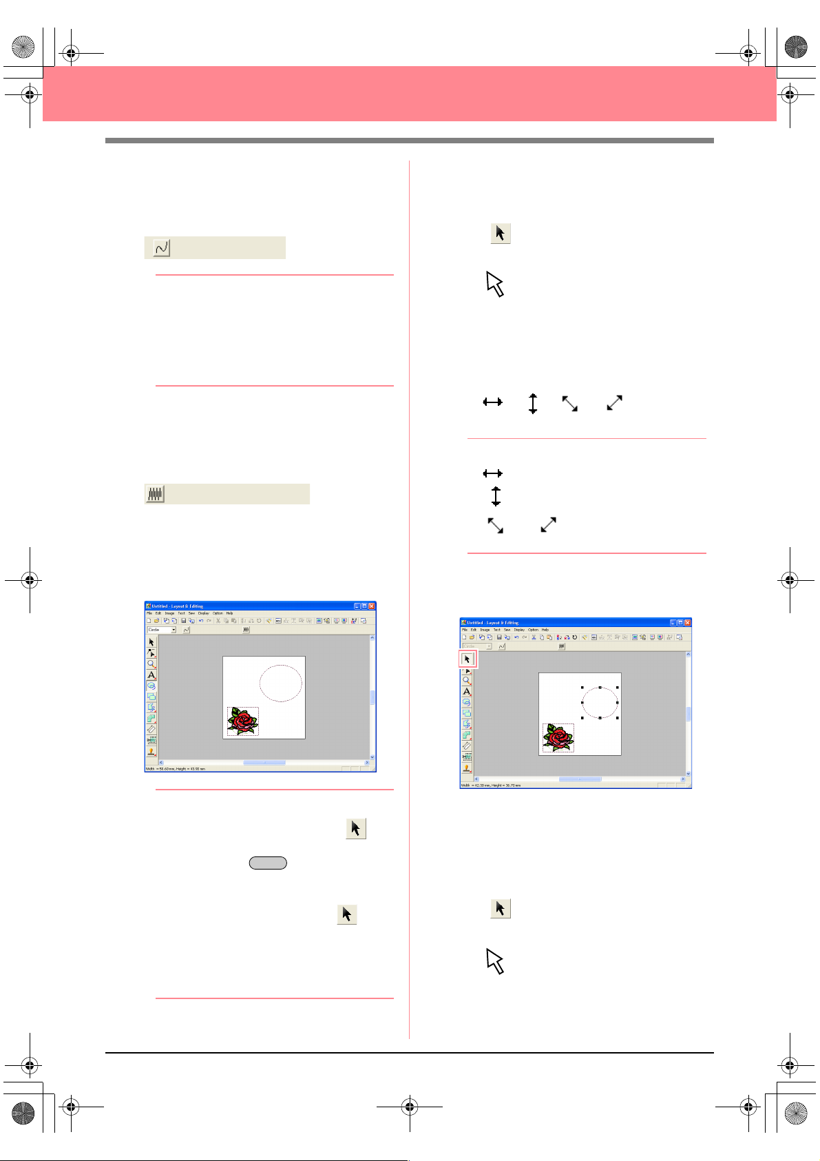
PeDesignV6Eng.book Page 42 Thursday, July 8, 2004 11:59 AM
Creating and Editing Embroidery Patterns
3. To cancel line sewing (outline), click the Line
sew button.
→ The Line color button and the Line sew
type selector disappear.
b Memo:
If the
Line sew
Line color
selector to disappear, the outline will not be
sewn. If you want to sew the outline, click the
Line sew
color
button and the
4. To cancel region sewing (inside area), click
the Region sew button.
→ The Region color button and Region
sew type selector disappear.
5. To draw the oval, drag the pointer in the
Design Page.
→ The oval (outline and inside area) ap-
pears when the mouse button is released.
button is clicked, causing the
button and the
button again to display the
Line sew type
Line sew type
Line
selector.
■ To change the size of the oval
If your oval looks very different from the one shown
above, modify its size as described below.
1. Click on the Tool Box.
→ The shape of the pointer changes to
.
2. Click the oval to select it.
3. Move the pointer over one of the handles of
the oval.
→ The shape of the pointer changes to
, , or , depending
on the handle that the pointer is over.
b Memo:
• is for scaling the width.
• is for scaling the height.
• and are for scaling both
dimensions at the same time.
4. Drag the handle to adjust the selected pattern
to the desired size.
42
b Memo:
• If you want to delete the oval, click on
the Tool Box, click the oval to select it, and
then press the key or select the
menu command
• If you want to change the color or sew type
of the oval after drawing it, click on
the Tool Box, click the oval to select it, and
then click the
button. The current attributes for the oval
appear in the Sewing Attributes bar, where
they can be changed.
Delete
Edit
–
Line sew
Delete
.
or
Region sew
■ To center the flower pattern in the
oval
If the flower pattern is not centered in the oval, move
the oval as described below.
1. Click on the Tool Box.
→ The shape of the pointer changes to
.
Page 51

PeDesignV6Eng.book Page 43 Thursday, July 8, 2004 11:59 AM
Creating and Editing Embroidery Patterns
2. Click the oval to select it.
→ The shape of the pointer changes to .
3. Drag the oval to its final location.
Step 4
Adding text
The next object to add to our embroidery pattern
is text.
1. Click on the Tool Box, and then click
.
→ The shape of the pointer changes to
, and the Sewing Attributes bar ap-
pears as shown below.
Font
Tex t S iz e
Text body color
Text body sew type
3. To change the text size, click in the Text Size
selector on the Sewing Attributes bar, and
then select the desired size for the text.
For this example, we will keep the default size
of 10.0 mm
b Memo:
The value indicates the height of the
characters.
4. To change the text color, click the Text body
color button ( ) on the Sewing Attributes
bar, click the desired color in the Region
Thread Color dialog box that appeared, and
then click Close.
For this example, since we will be using the
default color BLACK, you do not need to
change the text color setting.
5. To change the text sew type, click in the Text
body sew type selector, and then select the
desired sew type for the text.
For this example, we will use the default sew
type Satin stitch.
Basic Operation
2. To change the font, click in the Font selector
on the Sewing Attributes bar, and then select
the desired font.
For this example, since we will be using the
default font 01, you do not need to change the
font setting.
b Memo:
For more precise setting of the text
attributes, refer to “Specifying text attributes”
on page 157.
6. To enter the text, click in the Design Page.
Since we can move the text after creating it,
any place in the Design Page can be clicked.
43
Page 52
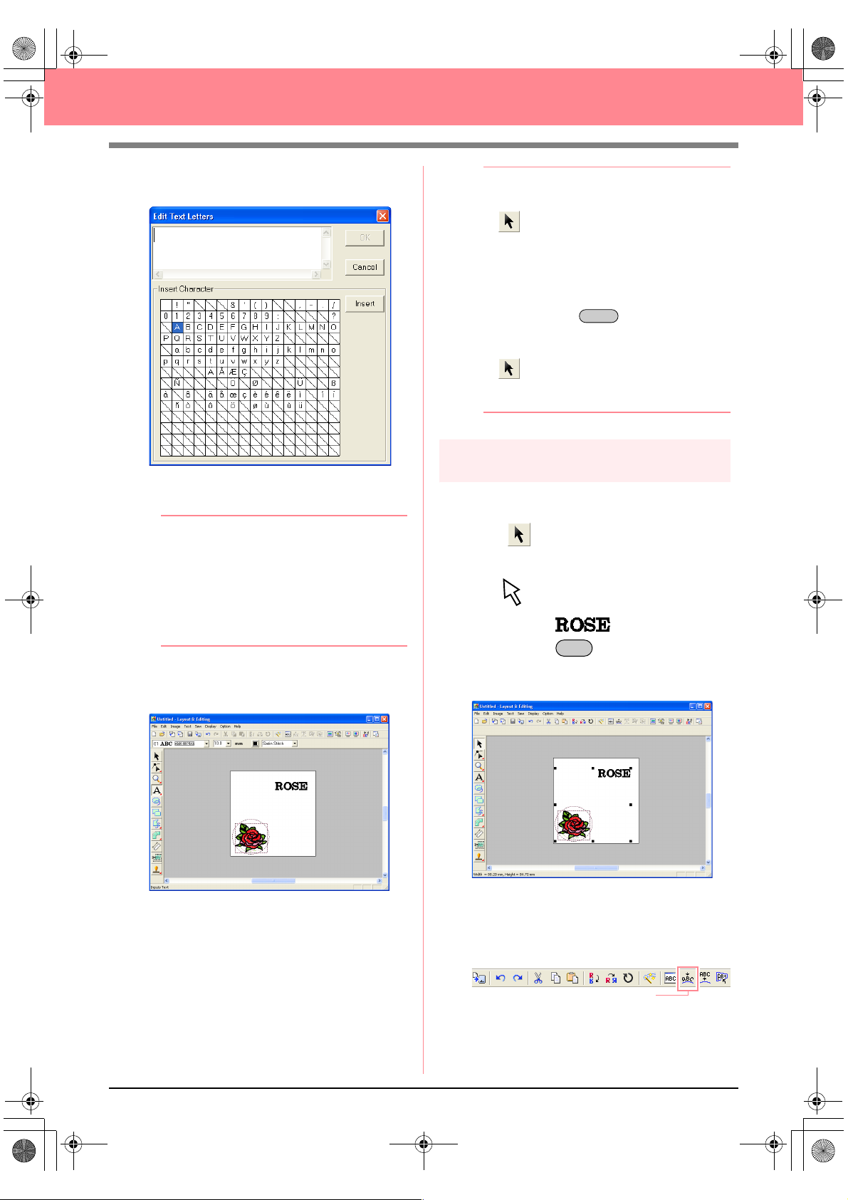
PeDesignV6Eng.book Page 44 Thursday, July 8, 2004 11:59 AM
Creating and Editing Embroidery Patterns
→ The Edit Text Letters dialog box ap-
pears.
7. Type your text (“ROSE”, for this example).
b Memo:
• You can also enter a character by
selecting it in the character table, then
Insert
clicking
clicking it. This is particularly useful if you
have to enter accented characters that are
not available on your keyboard.
• To quit the operation, click
8. Click OK.
→ The text is displayed in the Design Page.
, or simply by double-
Cancel
.
b Memo:
• If you want to edit the entered text, click
on the Tool Box, click the text to
select it, and then select the menu
command
text in the
that appeared.
• If you want to delete the text, select it, and
then press the key.
• If you want to change the text color, font or
other attributes after entering the text, click
select it, and then change the settings on
the Sewing Attributes bar.
Step 5
Fitting the text around the oval
Here, we are going to fit the text around the oval.
1. Click on the Tool Box.
→ The shape of the pointer changes to
2. Click the text to select it.
3. Hold down the key and click the oval to
select it.
→ Both the oval and the text are selected.
Text
–
Edit Letters
Edit Text Letters
Delete
on the Tool Box, click the text to
.
. Edit the
dialog box
Ctrl
44
4. Click Text on the menu bar, and then click Fit
Text to Path Setting.
An alternate method is to click the Toolbar
button indicated below.
Fit Text to path
Page 53

PeDesignV6Eng.book Page 45 Thursday, July 8, 2004 11:59 AM
Creating and Editing Embroidery Patterns
→ The Fit Text to Path Attribute Setting di-
alog box appears.
5. Click OK without changing any settings.
For more details on these settings, refer
c
to “Specifying text arrangement” on
page 158.
→ The text is now arranged on the oval.
Step 6
Adding a circle for the center of
the sun
The next object to add will be a sun. We will first
draw a circle to get the basic shape, and then
change the color, sew type and width of the
outline and the color and sew type for the inside
area.
1. To draw a circle, hold down the key
while drawing as described in “To add the
oval” on page 41.
Shift
b Memo:
If you need to modify the size of the circle,
select it, and then drag a handle at one of the
corners.
2. Click on the Tool Box, and then click the
circle to select it.
3. To change the color and sew type for the
outline, click the Line sew button ( ) so
Basic Operation
b Memo:
Moving the oval and text:
Once the text is arranged on the oval, you
can move both patterns as a group, without
affecting their relative position, or you can
move the text alone to change its position on
the oval.
To move both patterns as a group:
1) Click on the Tool Box, and then
click the oval to select it.
→
The shape of the pointer changes to
.
2) Drag the oval.
→
The text moves together with the
oval.
To move the text along the oval:
1) Click on the Tool Box, and then
click the text to select it.
→
The shape of the pointer changes to
.
2) Drag the text.
→
The text only moves along the oval.
that the Line color button ( ) and the Line
sew type selector ( ) appear, and
then select a line color and sew type.
For this example, select the color BLACK,
and leave the sew type set to Zigzag Stitch.
4. To change the sewing attributes for the
outline, click Sew on the menu bar, and then
click Sewing Attribute Setting.
An alternate method is to click the Toolbar
button indicated below.
Sewing Attribute Set
45
Page 54

PeDesignV6Eng.book Page 46 Thursday, July 8, 2004 11:59 AM
Creating and Editing Embroidery Patterns
→ The Sewing Attribute Setting dialog box
appears.
5. To change the width from 2.0 mm, set Zigzag
width to 1.0, and then click Apply.
6. To change the color for the region, click the
Region sew button ( ) so that the Region
color button ( ) and the Region sew type
selector ( ) appear, and then
select a region color.
For this example, select the color LEMON
YELLOW.
→ The embroidery pattern appears as
shown below.
Step 7
Selecting a programmable fill stitch
Next, we will select a special fill stitch pattern for the
inside area of the circle, and then change its
settings. Programmable fill stitch patterns, which
can be created in Programmable Stitch Creator
(refer to “Using Programmable Stitch Creator” on
page 54), are arranged in a tile-like manner within
the selected regions, creating more decorative
stitching.
b Memo:
Make sure that the circle is still selected.
1. Select Prog. Fill Stitch in the Region sew
type selector ( ).
2. Click Sew on the menu bar, and then click
Sewing Attribute Setting.
An alternate method is to click the Toolbar
button indicated below.
Sewing Attribute Set
→ The Sewing Attribute Setting dialog box
appears.
46
Page 55

PeDesignV6Eng.book Page 47 Thursday, July 8, 2004 11:59 AM
Creating and Editing Embroidery Patterns
3. Click under Programmable fill.
→ The Browse dialog box appears, allowing
you to preview and browse through the
existing programmable fill stitch patterns.
a Note:
Only programmable fill stitch files, which
have the .pas extension, are listed.
4. From the stitch samples, click pat 07 to select
it, and then click OK.
→ The dialog box closes and a preview of
the selected stitch appears at the bottom
of the Sewing Attribute Setting dialog
box.
b Memo:
Double-clicking the stitch pattern also selects
it and closes the dialog box.
5. To change the size of the programmable stitch
pattern in Beginner Mode, set the size to 10 ×
10 mm (0.30 × 0.30 inch) by moving the slide
to the right.
→ The Sewing Attribute Setting dialog box
appears as shown below.
b Memo:
• The preview of the stitch pattern at the
bottom of the dialog box changes each
time a setting is changed. This allows you
to see how each setting affects the pattern.
• To separately change the width and height
of the stitch pattern, click
, and then type or select the desired
mode
values in the appropriate boxes under
Programmable fill
6. To change the direction of the fill stitching,
click Constant under Direction, move the
pointer over the red arrow inside of the circle
under Constant, and then drag the red arrow
until 340 degrees is selected.
To Expert
.
Basic Operation
47
Page 56

Basic_01.fm Page 48 Friday, July 9, 2004 1:44 PM
Creating and Editing Embroidery Patterns
→ The Sewing Attribute Setting dialog box
appears as shown below.
For more information on the different
c
settings for a programmable fill stitch,
refer to “Specifying sewing attributes” on
page 171.
7. Click Apply.
→ The stitch and its settings are applied to
the inside area of the selected circle.
a Note:
The selected sewing attributes will be
applied to the regions of every object that will
be drawn, until the attributes are changed.
→ The shape of the pointer changes to
, and the Sewing Attributes bar ap-
pears as shown below
Path shape
Line sewing
.
Region sewing
2. Make sure that Close path is selected in the
Path shape selector.
b Memo:
When drawing a closed path, the first point
and the last point are automatically joined.
The pattern has an outline and an inside
area, and sewing attributes can be applied to
both.
With an open path, the broken line is left
open (the first and last point are not
automatically joined). The pattern will not
have a region, therefore you can only apply
sewing attributes to the outline.
3. To change the color and sew type for the
outline, click the Line sew button ( ) so
that the Line color button ( ) and the Line
sew type selector ( ) appear, and
then select a line color and sew type.
For this example, select the color RED, and
leave the sew type set to Zigzag Stitch.
4. To change the color for the inside area, click
the Region sew button ( ) so that the
Step 8
Adding a closed broken line for
the sun’s rays
Now, let’s draw a few rays around the sun. There
are, of course, many ways to do this. You could,
for example, draw a single straight line for each
ray. For this example, we will use a closed
polygonal line (broken line) to draw all of the rays
as a single star-shaped pattern.
1. Click on the Tool Box, and then click
.
48
Region color button ( ) and the Region
sew type selector ( ) appear,
and then select a region color.
For this example, select the color
VERMILION.
Page 57

PeDesignV6Eng.book Page 49 Thursday, July 8, 2004 11:59 AM
Creating and Editing Embroidery Patterns
5. To draw the rays of the sun around the circle
using the circle as a guide, click in the Design
Page to select the start point (1), continue
clicking in the Design Page to select every
other corner (2 through L), and then doubleclick.
3
1
K
I
G
2
L
J
H
F
D
E
5
7
4
6
8
0
B
C
9
A
b Memo:
To remove the last point that was entered,
click the right mouse button.
→ The embroidery pattern appears as
shown below.
Step 9
Changing the sewing order of
sun and rays
Since we have drawn the closed broken line for the
sun’s rays after drawing the circle, the sun’s rays
are on top of the circle. In other words, the broken
sun’s rays are in the foreground. Since the pattern
is in the foreground, it will be sewn last. We need to
change the sewing order so that the sun (circle) will
be sewn on top of the sun’s rays.
1. Click Sew on the menu bar, and then click
Sewing Order/Color.
An alternate method is to click the Toolbar
button indicated below.
Sewing Order/Color
→ The Sewing Order/Color dialog box
apears.
Basic Operation
b Memo:
• If you want to delete the pattern, click
on the Tool Box, click the pattern to select
it, and then press the key or
select the menu command
• If you want to change the pattern shape,
color, or sew type after drawing it, click
on the Tool Box, click the pattern to
select it, and then change the settings on
the Sewing Attributes bar or in the
Attribute Setting
Delete
Edit – Delete
Sewing
dialog box.
2. Click the frame containing the region for the
sun’s rays to select it, and then drag the frame
to the left of the circle for the sun. (This part of
the sun will be sewn first.).
b Memo:
When a frame in the
dialog box is selected, the buttons at the
bottom of the dialog become available. The
.
sewing order of the selected pattern object
can also be changed by using these buttons.
For more details, refer to “Checking and
Editing the Sewing Order/Color” on
page 184.
Sewing Order/Color
49
Page 58

PeDesignV6Eng.book Page 50 Thursday, July 8, 2004 11:59 AM
Creating and Editing Embroidery Patterns
3. Click the frame containing the outline for the
sun’s rays to select it, and then drag the
selected frame between the region for the
sun’s rays and the circle for the sun.
4. Click OK.
→ The sun’s rays will be sewn before the sun
(circle).
4. Drag the point to the new location.
If necessary, move the circle so that it looks
centered relative to the sun’s rays.
Step 10
Adjusting the rays
At this time, you might want to modify the rays.
You can do this by moving, deleting and adding
points in the closed broken line pattern.
1. Click on the Tool Box, and then click
.
→ The shape of the pointer changes to
.
2. Click the sun’s rays to select it.
→ The points in the pattern appear as small
empty squares.
3. Click the point that you want to move.
→ The selected point appears as a small
black square.
For details on adding and deleting points,
c
refer to “Inserting points” on page 136 and
“Deleting points” on page 137.
Step 11
Setting hole sewing
If the sun is sewn according to the current
settings, the sun’s rays will be sewn first, and then
the sun (circle) will be sewn on top of it. In order to
avoid sewing the same region twice, you can
specify hole sewing for a larger region that
completely encloses smaller ones. If hole sewing
is specified, the part of the rays behind the circle
will not be sewn.
50
Page 59

PeDesignV6Eng.book Page 51 Thursday, July 8, 2004 11:59 AM
Creating and Editing Embroidery Patterns
1. Click on the Tool Box, and then click the
sun’s circle to select it.
2. Hold down the key and click the sun’s
rays.
→ The circle and the broken line are now se-
lected together.
Ctrl
b Memo:
If it is difficult to select the two patterns, drag
the pointer to draw a selection frame around
the patterns.
3. Click Sew on the menu bar, and then click Set
Hole Sewing.
→ The following message appears.
a Note:
Hole sewing cannot be applied if one of the
patterns is not completely enclosed within
the other pattern.
Step 12
Previewing the embroidery
pattern
You can display a preview of the embroidery
pattern in order to see how the stitching is
connected, or you can display a realistic preview
of the embroidery pattern in order to see how the
pattern will appear once it is sewn. For example,
you will be able to see that the part of the broken
line (sun rays) behind the circle is not sewn and
how the selected programmable fill stitch will be
sewn.
1. To display a preview of the embroidery
pattern, click Display on the menu bar, and
then click Preview.
An alternate method is to click the Toolbar
button indicated below.
Preview
→ A preview of the embroidery pattern ap-
pears.
Basic Operation
4. Click OK to close the message.
a Note:
Patterns with hole sewing set cannot be
moved separately. To adjust their relative
positions, click on the Tool Box, select
one of the patterns, and then cancel hole
sewing by selecting the menu command
Sew – Cancel Hole Sewing
b Memo:
Points on the outlines can be edited
independently with the Point Edit tool. (For
details, refer to “Moving points” on page 135)
For more details, refer to “Specifying hole
c
sewing” on page 180.
b Memo:
.
2. To display a realistic preview of the entire
To zoom in (or out), click on the Tool
Box, click (or ), and then click the
desired area of the embroidery pattern.
embroidery pattern, deselect all objects in the
pattern by clicking in a blank area of the
Design Page.
To display a realistic preview of a single object
or a group of objects, select the object(s).
51
Page 60
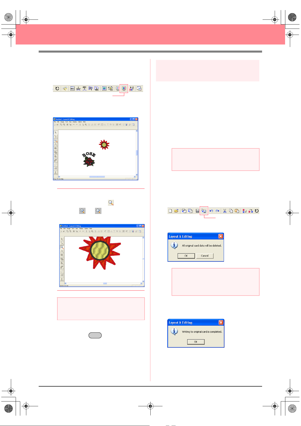
PeDesignV6Eng.book Page 52 Thursday, July 8, 2004 11:59 AM
Creating and Editing Embroidery Patterns
3. Click Display on the menu bar, and then click
Realistic Preview.
An alternate method is to click the Toolbar
button indicated below.
Realistic Preview
→ A realistic preview of the embroidery pat-
tern appears.
b Memo:
To zoom in (or out), click on the Tool
Box, click (or ), and then click the
desired area of the embroidery pattern.
Step 13
Transferring the pattern to an
original card
Before you can actually sew the embroidery
pattern, you must transfer the pattern to a sewing
machine. Transfer the embroidery pattern to the
sewing machine using media of the type used by
your machine, for example, original cards, floppy
disks, CompactFlash cards, or USB media. For
this example, we will transfer the pattern to an
original card.
1. Insert an original card into the USB card writer
module.
a Note:
The original card is inserted correctly when
you hear it snap into place.
2. Click File on the menu bar, point to Write to
Card, and then click Current Design on the
submenu.
An alternate method is to click the Toolbar
button indicated below.
Write to Card
a Note:
The embroidery pattern cannot be edited
while the realistic preview is displayed.
4. To return to the previous display, repeat step
3., or press the key.
Esc
→ The following message appears.
a Note:
If the original card is not brand new, make
sure that the patterns already stored on the
card are no longer needed.
3. Click OK.
→ The following message appears.
52
Page 61
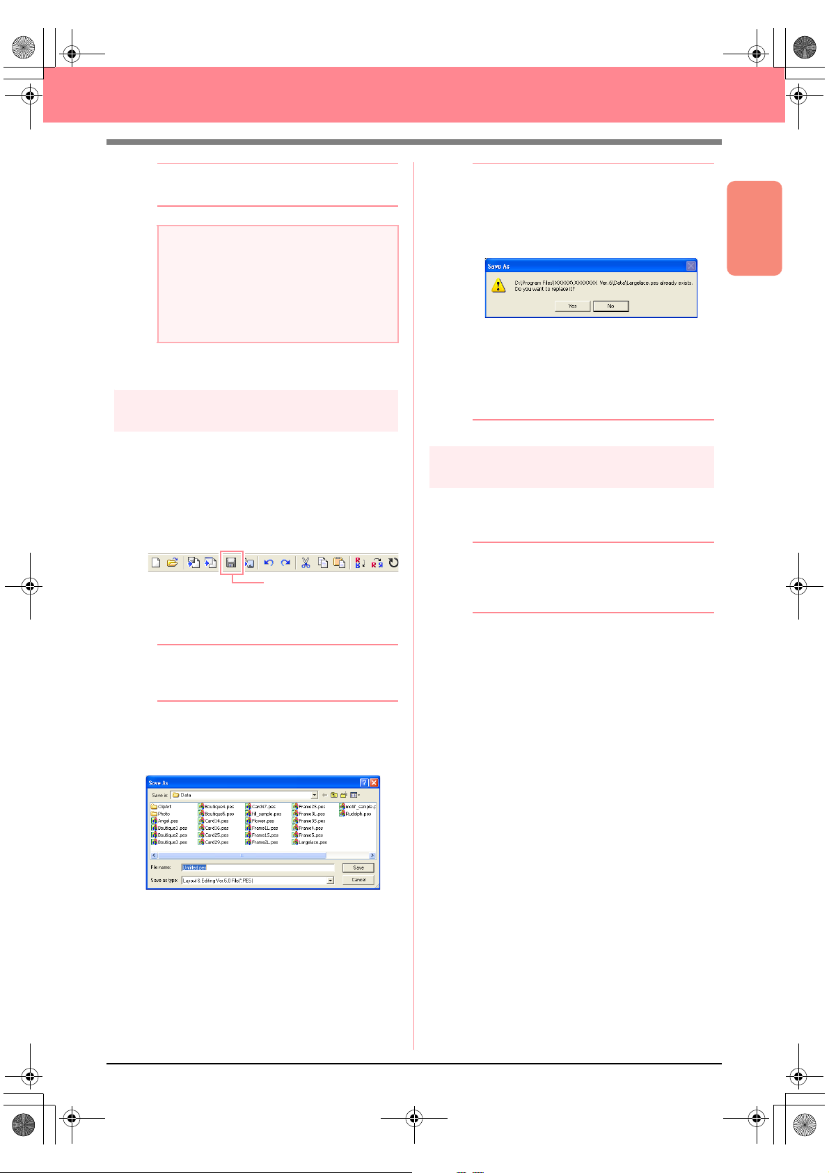
PeDesignV6Eng.book Page 53 Thursday, July 8, 2004 11:59 AM
Creating and Editing Embroidery Patterns
b Memo:
To quit the operation, click
Cancel
.
a Note:
If the card writer module is not correctly
connected or powered, or if the original card
is not inserted or is defective, an error
message will appear. For more details, refer
to “Writing an embroidery pattern to an
original card” on page 195.
4. Click OK to close the message.
Step 14
Saving the file
Once the embroidery pattern is finished, you may
want to save it in order to retrieve it later.
1. Click File on the menu bar, and then click
Save.
An alternate method is to click the Toolbar
button indicated below.
Save
→ If the pattern has already been saved at
least once, the file is saved immediately.
b Memo:
• To quit the operation, click
• If a file already exists with the name
specified in the
following message appears.
• To overwrite the file, click
new file name appears in the title bar
of the Layout & Editing window.
• If you do not want to overwrite the
existing file, click
enter a different file name.
Save As
Step 15
Quitting Layout & Editing
1. Click File on the menu bar, and then click Exit.
→ The Layout & Editing window closes.
Cancel
dialog box, the
Yes
No
. You can then
.
. The
b Memo:
Layout & Editing can also be closed by
clicking the close button on the right end of
the title bar.
Basic Operation
b Memo:
To save the file with a different name, use the
menu command
→ If no file name has been specified or if the
file cannot be found, the Save As dialog
box appears.
2. Select the drive and the folder, and then type
in the file name.
3. Click Save to save the pattern.
File
–
Save As
instead.
53
Page 62

PeDesignV6Eng.book Page 54 Thursday, July 8, 2004 11:59 AM
Creating and Editing Embroidery Patterns
Using Programmable Stitch Creator
Programmable Stitch Creator allows you to design fill stitch and motif stitch patterns that can be applied as a
programmable fill stitch or motif stitch both in Design Center and Layout & Editing, resulting in more decorative
embroidery patterns. When applied to enclosed regions, the fill stitch or motif stitch pattern fills the region in a
tile-like manner. When applied to lines, the motif stitch pattern is repeated along the length of the line. In
addition, the fill stitch patterns can be applied as an individual stamp to enclosed regions. You can create your
own fill stitch and motif stitch patterns or use the many stitch patterns provided with this application, with or
without editing them.
In this section, we are going to edit an existing stitch pattern, and then apply embossing/engraving effects to it.
The complete procedure will take you through the different steps of a normal working session with
Programmable Stitch Creator and will introduce you to its most important features.
Follow the instructions in this section step by step. If you have to interrupt this exercise for any reason, it is
recommended to save the file (refer to Step 5, “Saving the edited stitch pattern”, on page 58). You will be able
to retrieve it later and resume your work.
Step 1 Starting up Programmable Stitch Creator page 54
Step 2 Opening a programmable stitch pattern page 55
Step 3 Drawing lines to edit the stitch pattern page 56
Step 4 Applying embossing/engraving effects page 57
Step 5 Saving the edited stitch pattern page 58
Step 6 Quitting Programmable Stitch Creator page 58
Step 1
Starting up Programmable Stitch
Creator
1. Click , select All Programs, then
PE-DESIGN Ver.6. Select Programmable
Stitch Creator.
b Memo:
If a shortcut for Programmable Stitch Creator
was created, for example, on the desktop,
double-click it to start up the application.
→ The Programmable Stitch Creator window
appears.
b Memo:
To fill the entire screen with the
Programmable Stitch Creator window, click
the maximize button on the right end of the
title bar.
54
Page 63

PeDesignV6Eng.book Page 55 Thursday, July 8, 2004 11:59 AM
Creating and Editing Embroidery Patterns
Title bar
Menu bar
Toolbar
Tool Box
Status bar
Step 2
Opening a programmable stitch
pattern
For this exercise, we will edit one of the
programmable fill stitch patterns provided with the
application.
1. Click File on the menu bar, and then click
Open.
An alternate method is to click the Toolbar
button indicated below.
Close button
Maximize button
Minimize button
Work area
Preview window
b Memo:
If the
Preview
contents of the selected file will appear in the
Preview
3. Click Open to open the pattern file and to
close the dialog box.
check box is selected, the
box.
Basic Operation
Open
→ The Open dialog box appears.
2. Select the stitch pattern file wave1.pas in the
Pattern folder.
55
Page 64

PeDesignV6Eng.book Page 56 Thursday, July 8, 2004 11:59 AM
Creating and Editing Embroidery Patterns
b Memo:
• Double-clicking the file name also adds the
pattern to the work area and closes the
dialog box.
• To preview the available .pas files in the
selected folder, click
In the
Browse
click a stitch pattern to select it, and then
Open
click
open the file and to close both the
and
• Opening a .pas file (programmable fill
stitch pattern) automatically selects
Programmable Fill
file (motif stitch patterns) automatically
selects
stitch pattern to be created, use the
commands on the
→ The stitch pattern appears in the work
area of Programmable Stitch Creator.
(or double-click the pattern) to
Browse
dialog boxes.
Motif
mode. To change the type of
Browse
dialog box that appeared,
mode. Opening a .pmf
Mode
.
Open
menu.
Step 3
Drawing lines to edit the stitch
pattern
Now, we are going to draw a lines between the
displayed ones using the Line tool of the Tool Box.
b Memo:
For this example, we will use the grid setting
Medium
saved. Grid settings should be selected
depending on how detailed you want to draw.
Select the grid setting
detailed stitches and the grid setting
more simple stitches. For more information
on the grid settings, refer to “Changing the
grid settings” on page 222.
with which the stitch pattern was
Narrow
for more
Wide
for
1. Click on the Tool Box. Move the pointer
over the work area.
→ The shape of the pointer changes to
.
2. Move the pointer to the second vertical grid
line to the right of the leftmost wave, and then
click the top edge of the work area.
b Memo:
The horizontal and vertical lines that you
draw on the work area always follow the grid.
The points that you create by clicking are
inserted at the intersection of the horizontal
and vertical grid lines, enabling you to draw
diagonal lines as well. Therefore, regardless
of where you click, a point will automatically
be inserted at the nearest intersection.
56
a Note:
You can see a preview of the stitch pattern in
the
Preview
window.
3. Move the pointer parallel to the wave, and
then click the second vertical grid line to the
right of the corner in the leftmost wave.
b Memo:
To remove the last point that was entered,
click the right mouse button.
4. Repeat step 3. until you reach the end of the
wave, and then double-click the bottom edge
of the work area.
5. Repeat steps 2. through 4. to add another
wave between the rightmost wave.
Page 65

PeDesignV6Eng.book Page 57 Thursday, July 8, 2004 11:59 AM
Creating and Editing Embroidery Patterns
→ The pattern should appear as shown be-
low.
b Memo:
To edit points in the pattern, click on the
Tool Box, and then edit the points. (For
details on moving, inserting and delete
points, refer to “Editing Points in Outlines” on
page 81 or go back to Step 10, “Adjusting the
rays”, on page 50).
Step 4
Applying embossing/engraving
effects
A stamp can be made by sewing regions of a fill
stitch pattern with the fill stitch, satin stitch or the
base stitch set for the embroidery pattern in order
to create embossing and engraving effects.
In order to do this, the lines of the stitch pattern
must form closed regions. In our example, the
lines do not form closed regions, so we will need
to add enclosing lines.
5. Move the pointer along the bottom edge of the
work area, and then double-click the lowerright corner to draw a line along the bottom
edge of the work area.
Basic Operation
6. Click (Region (engrave)) on the Tool
Box, and then click the first and fourth wave
regions.
→ These regions appear in red and will be
sewn with short stitches to give the effect
of engraving.
7. Click (Region (emboss)) on the Tool
Box, and then click the second and fifth wave
regions.
→ This region appears in blue and will be
sewn with no dropped stitches to give the
effect of embossing.
1. Click on the Tool Box.
→ The shape of the pointer changes to
.
2. Click the upper-left corner of the work area.
3. Move the pointer along the top edge of the
work area, and then double-click the upperright corner to draw a line along the top edge.
4. Click the lower-left corner of the work area.
57
Page 66

PeDesignV6Eng.book Page 58 Thursday, July 8, 2004 11:59 AM
Creating and Editing Embroidery Patterns
Step 5
Saving the edited stitch pattern
In order to apply your edited stitch pattern as a
programmable fill stitch or as a stamp to a region
in Layout & Editing or Design Center, you must
first save it as a .pas file.
1. Click File on the menu bar, and then click
Save As.
→ The Save As dialog box appears.
b Memo:
To overwrite the original file, use the menu
command
2. Select the drive and the folder, and then type
in the file name.
File
–
Save
instead.
3. Click Save to save the pattern.
b Memo:
• To quit the operation, click
• If a file already exists with the name
specified in the
following message appears.
• To overwrite the file, click
new file name appears in the title bar
of the Programmable Stitch Creator
window.
• If you do not want to overwrite the
existing file, click
enter a different file name.
Save As
Step 6
Quitting Programmable Stitch
Creator
When you are finished creating stitch patterns in
Programmable Stitch Creator, you can close the
application.
Cancel
dialog box, the
Yes
No
. You can then
.
. The
1. Click File on the menu bar, and then click Exit.
→ If you have saved your file as described in
Step 5, “Saving the edited stitch pattern”,
the Programmable Stitch Creator window
closes immediately.
→ If you have made changes to the pattern
since the last time the file was saved, you
will be asked whether you want to save
the changes. Click Yes, and then follow
the procedure described in Step 5, “Saving the edited stitch pattern”.
b Memo:
Programmable Stitch Creator can also be
closed by clicking the close button on the
right end of the title bar.
58
Page 67

PeDesignV6Eng.book Page 59 Thursday, July 8, 2004 11:59 AM
Creating Large-Size Embroidery Patterns
A large-size embroidery pattern can be designed by specifying the size of the pattern, creating the embroidery
pattern, then automatically dividing the pattern into a size that can be embroidered. By separately
embroidering each section of the pattern side by side, large-size embroidery can be sewn. In addition, the
joining edges can be embroidered slightly overlapping in order to blend beautifully.
Some large-size patterns may not be appropriate for use with the split sewing feature. We recommend using
designs with many small filled areas, such as a bouquet of flowers, lace designs and embroidery created using
the Photo Stitch function. Since designs with very large filled areas may not align properly due to fabric pull,
we suggest these types of designs not be used.
In this section, we are going to adapt an existing embroidery pattern for large-size embroidery, and then sew it.
The complete procedure will take you through the different steps of a normal working session with a large-size
embroidery pattern and will introduce you to its most important options.
Follow the instructions in this section step by step. If you have to interrupt this exercise for any reason, it is
recommended to save the file (refer to Step 5, “Saving the pattern”, on page 61). You will be able to retrieve
it later and resume your work.
Basic Operation
Designing a large-size embroidery pattern
Step 1 Starting up Layout & Editing page 59
Step 2 Specifying a Design Page size page 60
Step 3 Creating the embroidery pattern page 60
Step 4 Checking the embroidering order page 61
Step 5 Saving the pattern page 61
Step 6 Transferring the pattern to an original card page 62
Step 7 Quitting Layout & Editing page 63
Embroidering large-size embroidery patterns
Step 1 Attaching stabilizer to the fabric page 63
Step 2 Marking the embroidering position page 63
Step 3 Hooping the fabric page 65
Step 4 Embroidering page 65
Designing a large-size embroidery pattern
Step 1
Starting up Layout & Editing
1.
Click , select All Programs, then
PE-DESIGN Ver.6. Select Layout & Editing
to open the Layout & Editing window.
→ The Layout & Editing window appears.
b Memo:
To fill the entire screen with the Layout &
Editing window, click the maximize button on
the right end of the title bar.
b Memo:
If a shortcut for Layout & Editing was
created, for example, on the desktop,
double-click it to start up the application.
59
Page 68
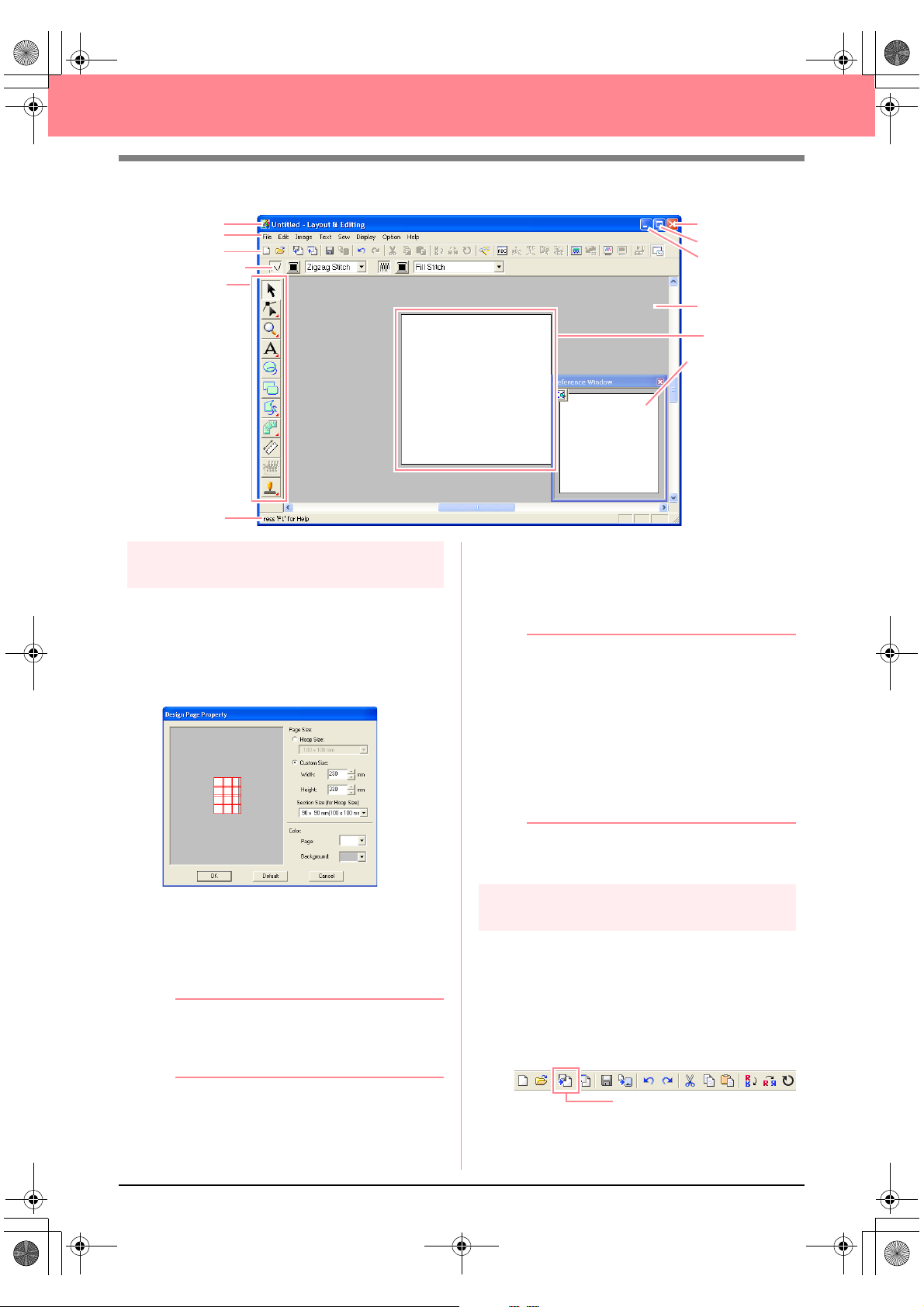
PeDesignV6Eng.book Page 60 Thursday, July 8, 2004 11:59 AM
Creating Large-Size Embroidery Patterns
Title bar
Menu bar
Toolbar
Sewing Attributes bar
Too l Bo x
Status bar
Step 2
Specifying a Design Page size
First, we need to specify the desired size for the
complete embroidery pattern.
1. Click Option, then Design Page Property.
→ The Design Page Property dialog box
appears.
Close button
Maximize button
Minimize button
Work area
Design Page
Reference Window
3. Click in the Section Size (for Hoop Size)
selector, and then select the size of the
sections (your embroidery hoop). For this
example, select 120 × 170 mm (130 × 180
mm).
b Memo:
• With the Section Size (for Hoop Size)
setting, the width and height of the
sections are 10 mm smaller than the
actual hoop size in order to provide
space for fine positioning adjustments
with adjacent sections.
• The preview area shows the setting
changes that you make. The double
lines indicate adjoining edges where
embroidering will overlap.
2. Select Custom Size, and then type or select
the desired width and height for the Design
Page. Enter dimensions between 100 and
1000 mm. For this example, set Width to 230
mm and Height to 330 mm.
b Memo:
The width and height specified under
Custom Size determine the exact size of
the embroidery design.
60
4. Click OK.
Step 3
Creating the embroidery pattern
For this example, we will use one of the lace
embroidery patterns provided with the application.
1. Click File on the menu bar, point to Import,
and then click from File on the submenu.
An alternate method is to click the Toolbar
button indicated below.
from File
Page 69

PeDesignV6Eng.book Page 61 Thursday, July 8, 2004 11:59 AM
Creating Large-Size Embroidery Patterns
→ The Import from File dialog box appears.
2. Select the embroidery pattern file
Largelace.pes in the Data folder.
b Memo:
If the
Preview
contents of the selected file will appear in the
Preview
check box is selected, the
box.
3. Click Import to import the embroidery pattern
file and to close the dialog box.
b Memo:
Double-clicking the file name also imports
the pattern into the Design Page and closes
the dialog box.
→ The embroidery pattern appears in the
Design Page. (To center the embroidery
pattern within the Design Page, select the
menu command Edit – Center.)
Step 4
Checking the embroidering order
→ The Design Property dialog box ap-
pears, and the first pattern section to be
sewn appears in the Design Page framed
with a red line.
a Note:
Before an embroidery pattern created in a
custom Design Page is saved or transferred
to an original card, running stitches are
added at the edges of the pattern sections
so that the pattern sections can easily be
aligned during sewing. This alignment
stitching appears in the
and cannot be edited. (For more details,
refer to “Embroidering” on page 65.)
NOT DEFINED
color
b Memo:
• The embroidering order cannot be
checked while the pattern is selected;
therefore, be sure to deselect the pattern
before selecting the menu command
Option – Design Property
refer to “Selecting patterns” on page 130.)
• The Design Page is automatically zoomed
in on or zoomed out from to fit in the entire
window, with the position of the displayed
pattern section within the embroidery hoop
installation order indicated at the top of the
dialog box.
• To display information for other pattern
sections in the embroidering order, click
Previous
• Pattern sections that do not contain any
stitching will not be displayed.
or
Next
.
. (For details,
Basic Operation
Before the embroidery pattern is sewn, check the
embroidering order to see the order that the
pattern sections are sewn and determine which
parts of the fabric should be hooped.
The pattern sections are sewn in order from left to
right, top to bottom.
1. Click Option on the menu bar, and then click
Design Property.
2. Click Close to close the dialog box.
Step 5
Saving the pattern
Once the embroidery pattern is finished, you may
want to save it in order to retrieve it later.
1. Click File on the menu bar, and then click
Save.
61
Page 70

PeDesignV6Eng.book Page 62 Thursday, July 8, 2004 11:59 AM
Creating Large-Size Embroidery Patterns
An alternate method is to click the Toolbar
button indicated below.
Save
→ If the pattern has already been saved at
least once, the file is saved immediately.
b Memo:
To save the file with a different name, use the
menu command
File
–
Save As
instead.
a Note:
If a section of the pattern exceeds the
maximum allowed for the stitch count or
number of colors, a message appears,
describing the limitations and asking
whether or not the pattern should be saved
anyway. If the embroidery pattern extends
off the Design Page, a message appears,
asking whether or not the pattern should be
saved anyway. If the pattern is saved
anyway, it must be edited before it can be
sewn.
→ If no file name has been specified or if the
file cannot be found, the Save As dialog
box appears.
2. Select the drive and the folder, and then type
in the file name.
3. Click Save to save the pattern.
b Memo:
• All patterns for a divided embroidery
pattern are saved as a single .pes (version
6) file.
• Only the sections that contain stitching are
saved.
Cancel
• To quit the operation, click
• If a file already exists with the name
specified in the
following message appears.
Save As
dialog box, the
.
Step 6
Transferring the pattern to an
original card
This embroidery pattern can be transferred to a
sewing machine, where it can be sewn. Transfer
the embroidery pattern to the sewing machine
using media of the type used by your machine, for
example, original cards, floppy disks,
CompactFlash cards, or USB media. For this
example, we will transfer the pattern to an original
card.
1. Insert an original card into the USB card writer
module.
a Note:
The original card is inserted correctly when
you hear it snap into place.
2. Click File on the menu bar, point to Write to
Card, and then click Current Design on the
submenu.
An alternate method is to click the Toolbar
button indicated below.
62
Yes
• To overwrite the file, click
new file name appears in the title bar
of the Layout & Editing window.
• If you do not want to overwrite the
existing file, click No. You can then
enter a different file name.
. The
Write to Card
→ The following message appears.
a Note:
If the original card already contains patterns,
they will be deleted.
Page 71
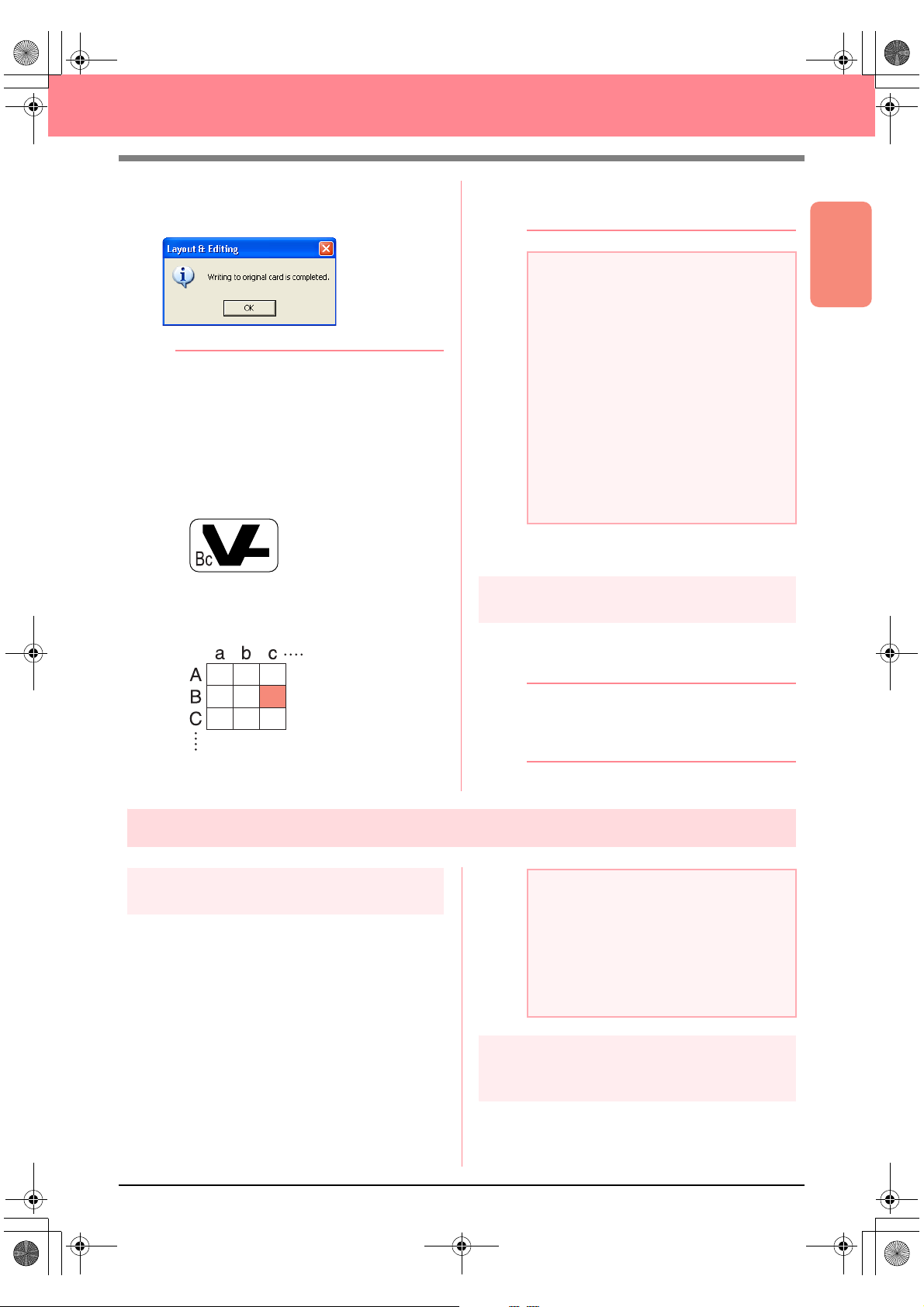
PeDesignV6Eng.book Page 63 Thursday, July 8, 2004 11:59 AM
Creating Large-Size Embroidery Patterns
3. Click OK.
→ The following message appears.
b Memo:
• Each section of the pattern is saved to the
original card as a separate pattern. When
the patterns are displayed on the sewing
machine’s display, they appear with two
letters in the lower-left corner, indicating
that section’s position in the entire pattern.
The uppercase letter indicates the row and
the lowercase letter indicates the column.
For example, for the pattern section
marked below in red, the pattern will
appear with “Bc” to indicate its position.
nine smaller patterns marked “Aa”, “Ab”,
“Ac”, “Ba”, “Bb”, “Bc”, “Ca”, “Cb” and “Cc”.
Cancel
• To quit the operation, click
.
a Note:
• If the card writer module is not correctly
connected or powered, or if the original
card is not inserted or is defective, an error
message will appear. For more details,
refer to “Writing an embroidery pattern to
an original card” on page 195.
• If a section of the pattern exceeds the
maximum size allowed, a message
appears, describing the limitations and the
pattern is not transferred to the original
card. In addition, if the pattern is too large
to be transferred to a single original card,
select the sections to transfer. For more
details, refer to “Writing an embroidery
pattern to an original card” on page 195.
4. Click OK to close the message.
Step 7
Quitting Layout & Editing
1. Click File on the menu bar, and then click Exit.
→ The Layout & Editing window closes.
Basic Operation
b Memo:
Layout & Editing can also be closed by
clicking the close button on the right end of
For the example shown above, the largesize embroidery pattern will be saved as
the title bar.
Embroidering large-size embroidery patterns
Step 1
Attaching stabilizer to the fabric
Stabilizer must always be used when
embroidering to stabilize the fabric. There are
many types of stabilizer; the type that you will use
depends on the type of fabric that you are
embroidering on. For large-size designs that are
split into sections, the stabilizer must be adhered
to the fabric, for example, by using iron-on
stabilizer, sticky stabilizer or spray adhesive.
When using spray adhesive, spray the adhesive
onto a hooped piece of stabilizer that is strong
enough for the entire large-size embroidery. In
some cases, you may need to use two pieces of
stabilizer for your embroidery.
a Note:
• For best results, attach the stabilizer to the
fabric (as described in Step 1 on this
page). Without the correct stabilizer, the
design may become misaligned due to
puckering in the fabric.
• Be sure to check the recommendations on
the stabilizer package.
Step 2
Marking the embroidering
position
Using the template for the size of hoop that you
are using, mark the embroidering position on the
fabric.
63
Page 72

PeDesignV6Eng.book Page 64 Thursday, July 8, 2004 11:59 AM
Creating Large-Size Embroidery Patterns
b Memo:
• The templates are included in the
package.
• The templates are also in the
Template
folder and can be printed out with a printer.
1. Punch a hole at the end of each arrow on the
template.
2. Place the template on the fabric, and then
insert the tip of a marking pen into each hole
to mark the fabric.
2. To mark an area to the right of the previously
marked area, align points A and D on the
template with marks B and C on the fabric.
AB
AB
DC
DC
To mark an area below the previously marked
area, align points A and B on the template with
marks C and D on the fabric.
AB
AB
DC
DC
3. Connect the points marked on the fabric to
draw reference lines.
For a large embroidery pattern, reposition the
template to draw the embroidering position for each
section of the embroidery pattern.
1. Place the template on the fabric, and mark
points A, B, C and D.
AB
DC
a Note:
• The intersection of the horizontal and
vertical line indicates the center of the
embroidery hoop.
•
While carefully considering how the fabric
will be hooped, place the template on the
fabric, and then draw lines to indicate the
embroidering position. In addition, because
all embroidery areas are not drawn on the
template for large embroidery hoops, be
careful that the embroidery area does not
extend from the marked area on the fabric as
shown below.
64
Page 73

PeDesignV6Eng.book Page 65 Thursday, July 8, 2004 11:59 AM
Creating Large-Size Embroidery Patterns
Step 3
Hooping the fabric
Using the hoop’s plastic embroidery sheet, align the
reference lines on the embroidery sheet with the marks
on the fabric. Then, hoop the fabric while making sure
that the fabric remains correctly aligned.
1. Insert the embroidery sheet into the inner ring
of the embroidery hoop, and then place them
on top of the fabric with the centerline on the
embroidery sheet aligned with the reference
lines (drawn on the fabric) for the first pattern
section to be sewn.
2. Keeping the reference lines on the embroidery
sheet aligned with the reference lines for the
first pattern section, place the fabric and inner
ring of the embroidery hoop into the outer ring
of the hoop, and then pull the fabric so that it
is tight.
a Note:
• Place the fabric and hoop on a level
surface, and then make sure that the inner
ring is pressed in well enough that the top
edge of the inner ring aligns with the top
edge of the outer ring.
• If the embroidery sheet is not used, the
marks on the embroidery hoop can be
used to hoop the fabric vertically and
horizontally.
However, since the center point on some
sewing machines is off center, the
embroidery sheet should be used for best
results.
• Another way to hoop the fabric is to use
sticky stabilizer that can be hooped
separately, tear away the protective
paper, then carefully align the fabric onto
the sticky surface using the embroidery
sheet as a guide.
• Tip: The fabric can be hooped more easily
if double-sided tape is affixed to the back
of the inside frame, which is placed on top
of the fabric, and then the fabric is
clamped between the inside frame and the
outside frame.
Step 4
Embroidering
Now, we are ready to embroider the pattern.
Basic Operation
3. Finish hooping the fabric, and then remove the
embroidery sheet.
1. When large-size embroidery patterns are
transferred to the sewing machine, the patterns
appear on the sewing machine display as
shown below. For this example, select the first
embroidery pattern section (Aa).
b Memo:
If there is no stitching in section Aa, select
the first section that contains stitching. Select
the menu command
Property
to check the embroidering order.
2. Attach the embroidery hoop to the sewing
machine, and then using the machine’s layout
adjusting functions, align the needle position
with the intersection of the lines drawn on the
fabric.
Option
–
Design
65
Page 74

PeDesignV6Eng.book Page 66 Thursday, July 8, 2004 11:59 AM
Creating Large-Size Embroidery Patterns
3. Embroider the selected pattern.
4. Remove the embroidery hoop from the sewing
machine, and then remove the fabric from the
hoop.
5. Hoop the fabric for the next pattern section.
(For details, refer to “Hooping the fabric” on
page 65.)
b Memo:
When an embroidery pattern created in a
custom Design Page is saved or transferred
to an original card, alignment stitching (single
lines of running stitches with the color
DEFINED
starting with securing stitches with a pitch of
0.3 mm) is added at the edges of the pattern
sections. (The alignment stitching appears in
the print preview and is printed in red.)
Example for hooping fabric using the
alignment stitching with Largelace.pes
(Largelace.pes can be found in the Data
folder.):
1) Embroider the upper-left pattern
, with a pitch of 10.0 mm, and
section.
→
Alignment stitching is sewn below
and on the right side of the
embroidered pattern section.
NOT
3) Hoop the fabric for the lower-left pattern
section with the top of the hoop aligned
on the alignment stitching at the bottom
of the pattern section sewn in step 1,
and then embroider the pattern.
→
Before the pattern section is
embroidered, alignment stitching is
sewn at the top. Make sure that this
alignment stitching aligns with the
alignment stitching sewn in step 1.
After the pattern section is
embroidered, alignment stitching is
sewn on the right side of the pattern
section.
4) Hoop the fabric for the lower-right pattern
section with the left side of the hoop
aligned on the alignment stitching on the
right side of the pattern section sewn in
step 3 and with the top of the hoop aligned
on the alignment stitching at the bottom of
the pattern section sewn in step 2, and
then embroider the pattern.
→
Before the pattern section is
embroidered, alignment stitching is
sewn on the left side and at the top.
Make sure that this alignment
stitching aligns with the alignment
stitching sewn in step 3 and in step 2.
66
2) Hoop the fabric for the upper-right pattern
section with the left side of the hoop
aligned on the alignment stitching on the
right side of the pattern section sewn in
step 1, and then embroider the pattern.
→
Before the pattern section is
embroidered, alignment stitching is
sewn on the left side. Make sure that
this alignment stitching aligns with the
alignment stitching sewn in step 1.
After the pattern section is
embroidered, alignment stitching is
sewn below the pattern section.
6. Continue hooping the fabric and embroidering
until the entire embroidery pattern is sewn.
Page 75

PeDesignV6Eng.book Page 67 Thursday, July 8, 2004 11:59 AM
Chapter 2
Advanced Operation
Design Center...................................................... 69
Layout & Editing ................................................. 106
Inputting Images and Embroidery Patterns .................................... 108
Editing Embroidery Patterns ........................................................... 130
Checking Embroidery Patterns ....................................................... 182
Saving and Printing......................................................................... 194
Changing Software Settings ........................................................... 202
Information for Optional Large-Size Hoop Users ............................ 203
Programmable Stitch Creator ............................ 208
Design Database ................................................. 223
67
Page 76

PeDesignV6Eng.book Page 68 Thursday, July 8, 2004 11:59 AM
Advanced Operations
About This Chapter
This chapter provides you with detailed procedures on the various operations that you can perform in each of
the applications.
Design Center
Design Center is used to manually create embroidery patterns from images using a four-stage procedure.
Stage 1 (Original Image Stage) c page 71
Stage 2 (Line Image Stage)
Stage 3 (Figure Handle Stage)
Stage 4 (Sew Setting Stage)
c page 73
c page 76
c page 83
Layout & Editing
Layout & Editing is used to automatically create embroidery patterns from images and to create embroidery
patterns by combining drawn objects and text.
Inputting Images and Embroidery Patterns c page 108
Editing Embroidery Patterns
Checking Embroidery Patterns
Saving and Printing
Changing Software Settings
Information for Optional Large-Size Hoop Users
c page 130
c page 182
c page 194
c page 202
c page 203
Programmable Stitch Creator
Programmable Stitch Creator allows you to create, edit and save fill/stamp and motif stitch patterns that can
be applied as a programmable fill stitch or a motif stitch, or as a stamp to the enclosed regions of
embroidery patterns.
c page 208
68
Design Database
Design Database allows you to organize the embroidery pattern files on your computer so that you can
easily preview them and find the desired pattern.
c page 223
Page 77

PeDesignV6Eng.book Page 69 Thursday, July 8, 2004 11:59 AM
Design Center
Design Center is used to create embroidery patterns from images created in other applications. With Design
Center, you can also apply stitch patterns created with Programmable Stitch Creator to regions of the
embroidery pattern. The resulting embroidery pattern can then be imported into the Layout & Editing Design
Page and combined with other patterns.
The embroidery pattern is created in four stages:
■ Stage 1 (Original Image Stage)
In stage 1, you can open an image (or clip art) from various sources, such as, an image created in Paint®, a
scanned drawing, or purchased clip art.
The image file must be in the uncompressed format, and its file name extension must be .bmp, .tif, .jpg, .j2k,
.pcx, .wmf, .png, .eps, .pcd, or .fpx.
Note that image files in other formats can be converted into the specified format if you have the proper
conversion software.
In stage 1, the image is displayed with its original colors and you cannot modify it.
Design Center
Advanced Opreation
■ Stage 2 (Line Image Stage)
When moving from stage 1 to stage 2, select a maximum of five colors from the image that will be converted
into black outlines. Unselected colors will be converted into white. You can then correct the black-and-white
image using pens and erasers of different thicknesses.
If you save a file in stage 2, its file name extension will be .pel.
■ Stage 3 (Figure Handle Stage)
When you move to stage 3, the application automatically detects the outline (black areas) and replaces it with
a set of broken lines. The broken lines can be edited (you can move and delete points or insert new points).
If you save a file in stage 3, its file name extension will be .pem.
■ Stage 4 (Sew Setting Stage)
You can set the sew type, thread color, and other sewing attributes for the outlines and regions to complete
the embroidery pattern.
If you save a file in stage 4, its file name extension will be .pem.
If you have to interrupt your work at stage 2, 3 or 4, save the file in order to retrieve it later to resume working
on it.
69
Page 78

PeDesignV6Eng.book Page 70 Thursday, July 8, 2004 11:59 AM
Design Center
Main Window
1
2
3
4
5
6
1 Title bar
2 Menu bar
Provides access to the functions.
3 Toolbar
Provides shortcuts for the menu commands.
4 Sewing Attributes bar
Sets the sewing attributes (color and sew type)
of the lines and regions in the pattern
(only in stage 4 (Sew Setting stage))
5 Tool Box
Used to select and edit the image or pattern.
Stage 1 has no Tool Box; the other stages all
have a different tools in the Tool Box.
A
0
9
8
7
6 Status bar
Provides helpful information, such as the size.
7 Reference Window
Displays all outlines and patterns in the work area, giving you an overview while you work on a
detailed area. (For more details, refer to “Viewing Patterns in the Reference Window” on
page 103.)
8 Design Page
The actual part of the work area that can be
saved and sewn.
9 Minimize button
0 Maximize button
A Close button
70
Page 79
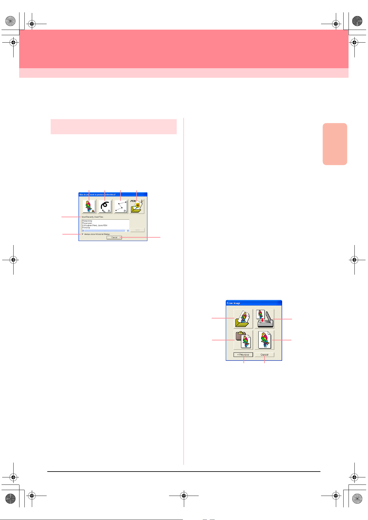
PeDesignV6Eng.book Page 71 Thursday, July 8, 2004 11:59 AM
Design Center
Stage 1 (Original Image Stage)
Importing Image Data
Using the wizard
This wizard provides a step-by-step guide for
creating embroidery patterns.
1. Click File, then Wizard.
→ The How do you want to produce em-
broidery? dialog box appears.
12
5
6
Position the pointer over any button, and the
name of the function appears.
The functions for each button are described
below.
1 From Image
Click this button when creating embroidery pattern from an image.
Clicking this button displays the From Image dialog box, and then continues with a step-by-step
guide for creating embroidery patterns.
For more details, refer to “When the From
c
Image button is clicked” on this page.
2 New Line Image
Clicking this button opens a new Design Page in
stage 2 (Line Image stage).
Click this button when you want to use the black
pen and eraser tools to draw an image, then create an embroidery pattern from that image.
For more details, refer to “Creating a new
c
Design Page in stage 2 (Line Image
stage)” on page 74.
3 New Figure
Clicking this button opens a new Design Page in
stage 3 (Figure Handle stage).
Click this button when you want to draw a figure
handle image, or when you want to create patterns from outlines taken from a previously
saved .pem file.
3
4
7
For more details, refer to “Creating a new
c
Design Page in stage 3 (Figure Handle
stage)” on page 78.
4 Open PEM
Click this button when you want to edit a saved
.pem file (saved in stage 3 (Figure Handle stage)
or 4 (Sew Setting stage)).
Clicking this button displays the Open dialog
box so that a .pem file can be selected.
5 Most Recently Used Files
A list of the most recently edited files are displayed.
From the list, click the name of the file that you
want to edit, and then click Open.
6 Always show Wizard at Startup
Select this check box to start up the wizard each
time Design Center is started up.
7 Cancel
Clicking this button closes this dialog box.
When the From Image button is clicked
When you click the From Image button in the How
do you want to produce embroidery? dialog box,
the From Image dialog box appears.
1
2
3
4
5 6
Position the pointer over any button, and the name
of the function appears.
Design Center
Advanced Opreation
71
Page 80

PeDesignV6Eng.book Page 72 Thursday, July 8, 2004 11:59 AM
Design Center Stage 1 (Original Image Stage)
The functions for each button are described below.
1 Open Image File
Click this button to open a previously saved image file and paste the image in the Design Page.
For details, refer to “Opening an image
c
file” on page 20.
2 From Clipboard
Clicking this button pastes the image on the Clipboard into the Design Page. This function can
only be used when there is an image on the Clipboard.
3 From TWAIN device
Click this button to import an image from a
TWAIN device (such as a scanner or digital camera) connected to your computer, then paste it in
the Design Page.
For details, refer to “Importing image data
c
from a TWAIN device” below.
4 Use Current image
Click this button to use an image opened in
stage 1 (Original Image stage). This function can
only be used when an image is opened in stage
1.
5 Previous
Clicking this button closes the current dialog
box, and returns to the How do you want to
produce embroidery? dialog box.
6 Cancel
Clicking this button closes this dialog box.
→ If any button other than Previous or Can-
cel is clicked, the image will be imported
and pasted into the Design Page of stage
1 (Original Image stage), and the Cut out
to Line Image dialog box appears, allowing you to choose colors for outlines.
For details on the next stages, refer to
c
“Continuing to Stage 2 (Line Image
Stage)” on page 73, “Continuing to Stage
3 (Figure Handle Stage)” on page 76,
then “Continuing to Stage 4 (Sew Setting
Stage)” on page 83.
1. Check that the scanner or other TWAIN
device is correctly connected to your
computer.
2. Click File, then Select TWAIN device.
→ The Select Source dialog box appears.
!!scr94.bmp!!
3. From the Sources list, click the desired device
to select it.
a Note:
If no TWAIN device is installed, there will be
no names displayed in the
First, install the driver software for the
TWAIN device that you want to use.
4. Click Select to choose the selected device
and to close the dialog box.
b Memo:
To quit the operation and close the dialog
box, click
5. Click File, then Input from TWAIN device.
→ The driver interface for the device select-
ed in the Select Source dialog box appears.
6. Specify the necessary settings for importing
an image, and then import the image.
Cancel
.
a Note:
For information on using the driver interface,
refer to the help manual for that interface, or
contact the manufacturer of the interface.
Sources
list.
Importing image data from a
TWAIN device
TWAIN is an application interface (API)
standardization for software that controls scanners
and other devices. Design Center supports TWAIN
standardized devices, allowing you to control the
device and import the image directly.
72
→ When the image transfer between the
scanner (or other device) and the driver is
completed, the imported image will be
pasted in a Design Page of stage 1 (Original Image stage).
b Memo:
If the image currently displayed in the Design
Page has not yet been saved, you will be
asked whether you want to save it.
Page 81

PeDesignV6Eng.book Page 73 Thursday, July 8, 2004 11:59 AM
Design Center
Stage 2 (Line Image Stage)
Continuing to Stage 2 (Line Image Stage)
After opening the image, continue to stage 2 (Line Image stage), where the color(s) that will be used to create
the line image (outline of the image) will be selected. In stage 2 (Line Image stage), you can edit the image
using the pen and eraser tools. You may also want to use these tools to create outlines that are easier to draw
by hand, for example, free-hand writing. Use the zooming tools available to display the image enlarged or
reduced.
Toolbar button:
1. Click , or click Stage, then To Line
Image.
→ The Cut out to Line Image dialog box ap-
pears.
→ If you were in stage 3 (Figure Handle
stage), you are returned to stage 2, unless you have modified the image in stage
3. In that case, a message will appear,
asking you to confirm that you want to
abandon the changes made in stage 3.
→ The selected color appears in the top box
under Pick Colors, and appears in
the check box to show that the color is selected.
b Memo:
• You can repeat step 2. to select up to five
colors. If more than five colors are
selected, only the last five colors selected
remain in the list.
• To deselect a color, clear the
corresponding check box.
• To adjust the color tone and reduce image
noise (distortions), click
more details, refer to “Image tuning” on
page 74.)
Image Tune
. (For
3. Click Preview to preview the line image in the
Design Page.
b Memo:
If necessary, the settings can be changed.
After changing the settings, click
preview the outline with the new settings
applied.
Preview
to
Design Center
Advanced Opreation
b Memo:
To display the image enlarged (or reduced),
move the
the image is enlarged, you can scroll through
it to display different parts.
ZOOM
slider up (or down). When
a Note:
If you started with stage 3 (Figure Handle
stage) by opening a stage 3 file, you cannot
go to stage 2.
2. Click the outline color(s) that you want to
convert into black outlines.
→ When the pointer is moved over the im-
age, the shape of the pointer changes to
.
4. Click OK.
→ All of the selected colors are converted to
a black outline (line image), which is displayed in the Design Page of stage 2 (Line
Image stage).
!!scr34.bmp!!
73
Page 82

PeDesignV6Eng.book Page 74 Thursday, July 8, 2004 11:59 AM
Design Center Stage 2 (Line Image Stage)
b Memo:
• To quit the operation and go back to stage
1 (Original Image stage), click
• It is recommended to select just as many
colors as necessary to create a clear
outline of the image. In the above
example, only a single color was selected.
• If you do not like the result, select the
menu command
to go back to stage 1 (Original
Image
Image stage), and then create the line
image again.
Stage
Image tuning
Clicking the Image Tune button in the Cut out to
Line Image dialog box displays an Image Tune
dialog box similar to the one shown below.
Image window
Cancel
–
To Original
.
b Memo:
• To close the dialog box without applying
the changes to the settings, click
OK
• Clicking
Cut out to Line Image
the
resets the
Pick Colors
Cancel
list on
dialog box.
a Note:
The image adjustments selected in the
Image Tune
image displayed in the
Image
from these adjustments cannot be saved.
dialog box apply only to the
Cut out to Line
dialog box; the image that results
Creating a new Design Page
in stage 2 (Line Image stage)
Toolbar button:
1. Click , or click File, then New Line
Image.
→ If the current Design Page has already
been saved or has not been edited, a new
Design Page immediately appears in
stage 2 (Line Image stage).
→ If the current Design Page has not been
saved, you will be asked whether you
want to save the changes.
.
From this dialog box, you can reduce the colors of
the image data (posterize) or reduce image noise
(distortions). By applying an even gradation to make
the image smoother, you can select colors more
easily, even from image data that was taken from a
scanner or other device and does not have clear
outlines.
1) The image window displays the image
resulting from the current settings.
2) Move the Tone slider to set the amount of
color reduction (posterization). Set to High to
show the original image. Set towards Low to
increase the color reduction.
3) If the Noise Reduction check box is
selected, the smaller areas of noise are
removed.
Click OK to show the corrected image in the
4)
image window on the
dialog box and to close the dialog box.
Cut out to Line Image
74
b Memo:
In stage 2 (Line Image stage), the file will be
saved as a .pel file.
“Importing image data from a TWAIN
c
device” on page 72, “Saving” on
page 104, and “Creating a new Design
Page in stage 3 (Figure Handle stage)” on
page 78
Drawing and erasing outlines
Drawing outlines
1. On the Tool Box, click the button for the pen
with the desired thickness.
→ The shape of the pointer changes to
2. To add a dot, click once. To draw a line, drag
the pointer.
.
Page 83

PeDesignV6Eng.book Page 75 Thursday, July 8, 2004 11:59 AM
Design Center Stage 2 (Line Image Stage)
b Memo:
To draw vertical or horizontal lines, hold
down the key while moving the
pointer.
Erasing outlines
1. On the Tool Box, click the button for the eraser
with the desired thickness.
Shift
2. Move the pointer over the line that you want to
erase, and then hold down the right mouse
button.
→ The shape of the pointer changes to
.
3. Drag the pointer to erase the line.
Design Center
Advanced Opreation
75
Page 84

PeDesignV6Eng.book Page 76 Thursday, July 8, 2004 11:59 AM
Design Center
Stage 3 (Figure Handle Stage)
Continuing to Stage 3 (Figure Handle
Stage)
After creating the outline, which is simply a collection of dots (or pixels) in stage 2 (Line Image stage), continue
to stage 3 (Figure Handle stage), where the dots are automatically connected to create lines that can be
edited. In stage 3 (Figure Handle stage), you can use the Point Edit tool to move, delete and insert points, or
you can use the Line tool to draw lines.
Toolbar button:
1. Click , or click Stage, then To Figure
Handle.
→ If you were in stage 2 (Line Image stage),
the Figure Object Conversion Setting
dialog box appears.
!!scr97.bmp!!
2. Select a setting under Resolution.
This setting determines how detailed the
generated figure handle image will be.
Basically, the line image is converted into
pieces of broken lines. To create more details,
more points are needed on the broken lines,
which also increases the size of the file.
In general, Normal provides a sufficient
resolution without making the file too large.
If selecting Coarse gives a satisfactory result
for a particular image, select this setting in
order to keep the file as small as possible.
Select Fine only if the image contains many
small details, and the Normal setting does not
give a satisfactory result.
3. To replace the black outlines with figure
handle lines along the center of the outlines,
select the Thinning Process check box, and
then use the slider to select the degree of
detail.
b Memo:
When the slider is set to
thick black lines will be replaced with a line
along the center.
To replace the black lines with figure handle
lines following the border of the outlines, clear
the Thinning Process check box.
Much
ON
OFF
, even very
76
4. Use the SIZE slider to set the size.
Page 85

PeDesignV6Eng.book Page 77 Thursday, July 8, 2004 11:59 AM
Design Center Stage 3 (Figure Handle Stage)
a Note:
You will not be able to enlarge the image
beyond the limits of the Design Page area. If
necessary, click
and then change the Design Page size in the
dialog box that appeared.
Design Page Property
5. To select a specific part of the image, click
Pick Area, drag the pointer ( ) across the
image in the Design Page to select the desired
area.
b Memo:
The
Figure Object Conversion Setting
dialog box appears again when the mouse
button is released.
6. Click OK.
→ The figure handle image is displayed in
the Design Page of stage 3 (Figure Handle stage).
Specifying the Design Page size
In stage 3 (Figure Handle stage), you can select a
,
Design Page size according to the size of hoop that
you will be using with your sewing machine, or you
can customize the size to fit even very large
embroidery patterns.
1. Click Option, then Design Page Property.
→ The Design Page Property dialog box
appears.
2. Select the Design Page size.
To adjust the Design Page size according to
the hoop size, select Hoop Size, and then
select the desired hoop size from the selector.
To specify a custom Design Page size, select
Custom Size, and then type or select the
desired width and height for the Design Page.
(The setting range is 100 to 1000 mm (3.9 to
39.4 inches).)
Design Center
Advanced Opreation
b Memo:
To close the dialog box without applying the
changes to the settings, click
Cancel
a Note:
If the outline data cannot be created from the
image when moving from stage 2 (Line Image
stage) to stage 3 (Figure Handle stage), even
after various outline conversion settings are
specified, return to stage 2, and correct the
outlines in the line image or apply corrections
from the image.
“Creating a new Design Page in stage 2
c
(Line Image stage)” on page 74,
“Continuing to Stage 4 (Sew Setting
Stage)” on page 83, “Changing the grid
settings” on page 105, and “Specifying
the Design Page size” on this page
b Memo:
• The preview area shows the setting
changes that you make.
• When
.
Hoop Size
machine image shows the orientation of
the Design Page (hoop) in relation to the
machine.
is selected, the sewing
a Note:
• When
Hoop Size
select a size larger than the maximum
embroidering area for your machine.
is selected, do not
3. Click OK.
b Memo:
• To return to the default settings (100 × 100
(
4" × 4"
) of
mm
• To close the dialog box without applying
the changes to the settings, click
Hoop Size
), click
Default
Cancel
.
.
77
Page 86
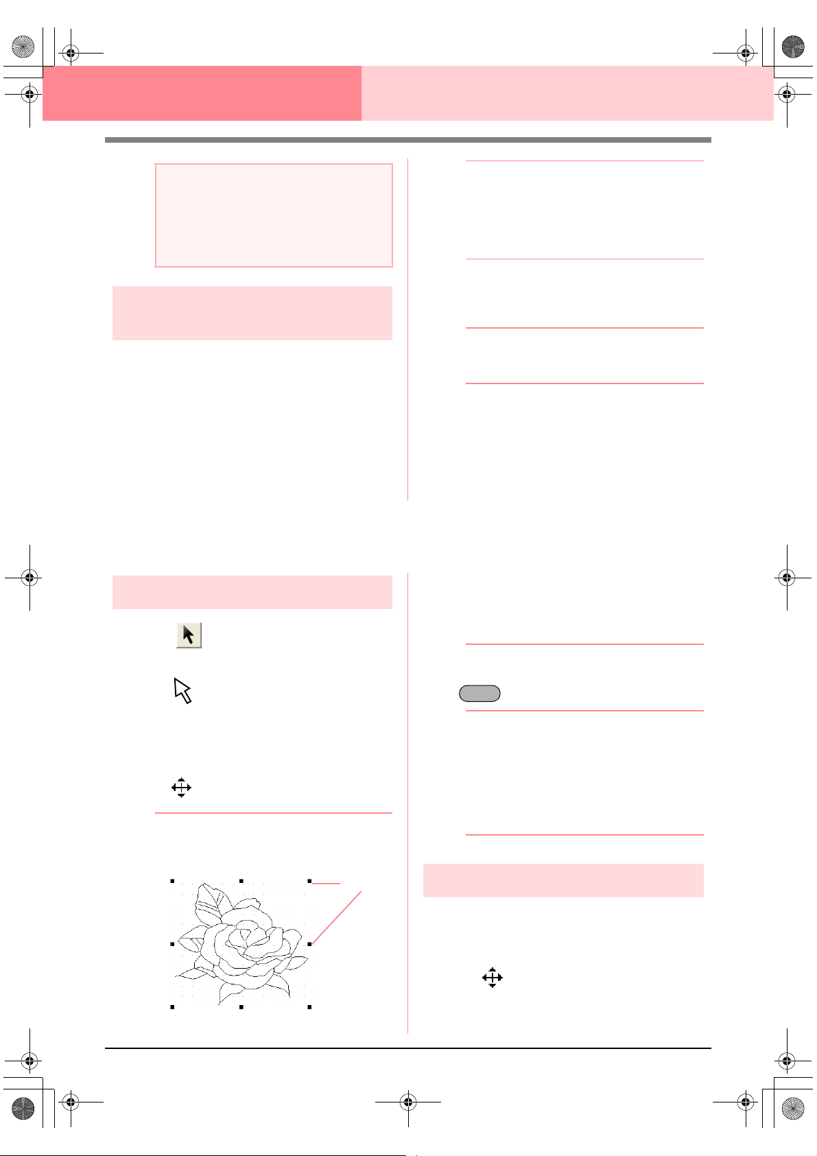
PeDesignV6Eng.book Page 78 Thursday, July 8, 2004 11:59 AM
Design Center Stage 3 (Figure Handle Stage)
a Note:
• Custom Design Page sizes cannot be
saved for version 5 and earlier.
• The selected size will be applied to every
new Design Page, until the settings are
changed.
Creating a new Design Page in
stage 3 (Figure Handle stage)
An empty Design Page can be created in order to
draw a figure handle image or to create patterns
from outlines taken from a previously saved .pem
file.
1. Click File, then New Figure Data.
→ If the current Design Page has already
been saved or has not been edited, a new
Design Page immediately appears in
stage 3 (Figure Handle stage).
Editing Outlines
b Memo:
• The size of the Design Page is the
currently selected size.
• To retrieve data from a saved .pem file,
use the menu command
Figure
.
→ If the current Design Page has not been
saved, you will be asked whether you
want to save the changes.
File
–
Import
b Memo:
In stage 3 (Figure Handle stage), the file will
be saved as a .pem file.
“Importing image data from a TWAIN
c
device” on page 72, “Saving” on
page 104, and “Creating a new Design
Page in stage 2 (Line Image stage)” on
page 74
Selecting outlines
1. Click on the Tool Box.
→ The shape of the pointer changes to
.
2. Click the outline that you want to select.
→ When the pointer is moved over the out-
line, the shape of the pointer changes to
.
b Memo:
• When the outline is selected, handles
appear and the outline appears in blue.
Handles
• The outline will not be selected if an empty
part of it is selected.
• To deselect the outline, select a different
outline, or click in a blank area of the
Design Page.
3. To select an additional outline, hold down the
key and click the other outline.
Ctrl
b Memo:
You can also select outlines by dragging the
pointer across the outline that you want to
select. As you drag the pointer, a selection
frame is drawn. All outlines that are
completely contained in that selection frame
are selected when the mouse button is
released.
Moving outlines
1. Select the outline that you want to move.
→ When the pointer is moved over the out-
line, the shape of the pointer changes to
78
.
2. Drag the outline to the desired location.
Page 87

PeDesignV6Eng.book Page 79 Thursday, July 8, 2004 11:59 AM
Design Center Stage 3 (Figure Handle Stage)
b Memo:
• To move the outline horizontally or
vertically, hold down the key while
dragging it.
• Pressing the arrow keys moves the
selected outline 0.5 mm (about 0.02 inch)
in the direction of the arrow on the key.
Shift
Scaling outlines
■ Scaling manually
1. Select the outline that you want to resize.
2. Move the pointer over one of the handles of a
selected outline or group of outlines.
→ The shape of the pointer changes to
, , or , depending
on the handle that the pointer is over.
b Memo:
• is for scaling the width.
• is for scaling the height.
5. Type or select the desired width and height.
b Memo:
• Select
• If the
6. Click OK.
100%
unchanged.
changing one dimension automatically
changes the other so that the proportion of
the width and height remains unchanged.
to leave the outline
aspect
check box is selected,
b Memo:
• To preview the outline at the new size in
the Design Page, click
• To close the dialog box without applying
the changes to the settings, click
Preview
.
Cancel
a Note:
• You cannot enter a size that will cause the
outline to exceed the size of the Design
Page.
• The minimum value is 1 mm (0.04 inch).
“Changing the measurement units” on
c
page 105
Design Center
Advanced Opreation
.
• and are for scaling both
dimensions at the same time.
3. Drag the handle to adjust the selected
outline(s) to the desired size.
■ Scaling numerically
1. Select the outline that you want to resize.
2. Click Edit, then Numerical Setting, then Size.
→ The Size dialog box appears.
3. To change the width and height proportionally,
select the aspect check box.
4. Select the whether the width and height will be
set as a percentage (%) or a dimension
(millimeters or inches).
Flipping outlines
horizontally or vertically
1. Select the outline that you want to flip
horizontally (up/down) or vertically (left/right).
2. To flip the outline horizontally, click Edit, then
Mirror, then Horizontal, or click on the
Toolbar.
To flip the outline vertically, click Edit, then
Mirror, then Vertical, or click on the
Toolbar.
Rotating outlines
■ Rotating manually
1. Select the outline that you want to rotate.
2. Click Edit, then Rotate, or click on the
Toolbar.
→ The handles around the selected outline
are replaced by small squares at the four
corners of the selected outline.
79
Page 88

PeDesignV6Eng.book Page 80 Thursday, July 8, 2004 11:59 AM
Design Center Stage 3 (Figure Handle Stage)
3. Move the pointer over one of the four rotation
handles.
→ When the pointer is moved over a rotation
handle, the shape of the pointer changes
to .
4. Drag the rotation handle clockwise or
counterclockwise to rotate the outline in 1°
increments.
b Memo:
To rotate the outline in 15° increments, hold
down the key while dragging the
rotation handle.
■ Rotating numerically
1. Select the outline that you want to rotate.
2. Click Edit, then Numerical Setting, then
Rotate.
→ The Rotate dialog box appears.
Shift
4. Click OK.
b Memo:
• To preview the outline at the new angle in
the Design Page, click
• To close the dialog box without applying
the changes to the settings, click
Preview
.
Cancel
a Note:
The range of values that can be entered is
between 0 and 359 degrees, in 1-degree
increments.
Deleting outlines
1. Select the outline to be deleted.
2. Press the key, or click Edit, then
Delete.
Delete
.
3. Type or select the desired rotation angle.
b Memo:
• The angle can also be specified by moving
the pointer over the red arrow inside of the
circle, then dragging the red arrow to the
desired angle. When the pointer is moved
over the red arrow, its shape changes to
.
•Select
unchanged.
0 degree
to leave the outline
80
Page 89

PeDesignV6Eng.book Page 81 Thursday, July 8, 2004 11:59 AM
Design Center Stage 3 (Figure Handle Stage)
Editing Points in Outlines
Moving points
1. Click on the Tool Box.
→ The shape of the pointer changes to
.
2. Click the outline that you want to edit.
→ The outline appears in pink, and the
points in the selected outline appear as
small empty squares. The points at the
ends of lines appear as larger squares.
3. Click the point that you want to move.
→ The selected point appears as a small
black square.
Inserting points
1. Click on the Tool Box.
→ The shape of the pointer changes to
.
2. Click the outline that you want to edit.
→ The outline appears in pink, and the
points in the selected outline appear as
small empty squares. The points where
lines overlap appear as larger squares.
3. Click the outline at the position where you
want to insert a new point.
→ A new point, appearing as a small black
square, is added. The new point can be
edited.
Deleting points
1. Click on the Tool Box.
→ The shape of the pointer changes to
.
Design Center
Advanced Opreation
b Memo:
To select additional points, hold down the
key and click each point, or drag the
Ctrl
pointer over the points that you want to
select.
a Note:
If you click the line instead of a square, a
new point is inserted.
4. Drag the point to the new location.
→ All selected points move in the same di-
rection.
b Memo:
• To move the point horizontally or vertically,
hold down the key while dragging
it.
• Pressing the arrow keys moves the
selected point 0.1 mm (about 0.01 inch) in
the direction of the arrow on the key.
Shift
2. Click the outline containing the point that you
want to edit.
→ The points in the outline appear as small
empty squares.
3. Click the point that you want to delete.
→ The selected point appears as a small
black square.
b Memo:
To select additional points, hold down the
key and click each point, or drag the
Ctrl
pointer over the points that you want to
select.
4. Press the key to remove the point
from the outline.
Delete
a Note:
The points where lines overlap, which
appear as red squares, cannot be deleted.
81
Page 90

PeDesignV6Eng.book Page 82 Thursday, July 8, 2004 11:59 AM
Design Center Stage 3 (Figure Handle Stage)
Drawing a Broken Line
The line drawing mode allows you to add broken lines to your pattern. A broken line is made of one or more
adjacent straight lines, in other words, the end point of one straight line is the start point of the next one.
If the broken line that you draw did not create enclosed regions, it remains a simple outline, and you can only
set sewing attributes for the line itself in stage 4 (Sew Setting stage).
If the broken line created enclosed regions, you can assign sew types and colors to both the outline and the
regions in stage 4.
If you draw a line through an existing region, creating two separate regions, you will be able to set sewing
attributes for both regions separately, as well as for the separating line.
End point
Start point
Broken line without a region
Broken lines with two regions
1. Click on the Tool Box.
→ When the pointer is moved over the work
area, the shape of the pointer changes to
.
2. To draw a line, click in the Design Page to
specify the start point.
3. Move the pointer, and then click in the Design
Page to specify the next point.
→ The two points are connected with a
straight line.
b Memo:
• To remove the last point that was entered,
click the right mouse button.
If necessary, use the grid to help draw the
lines. You can set the grid so that each of
its vertical and horizontal lines are visible.
For details on the grid, refer to “Changing
the grid settings” on page 105.
• To draw vertical or horizontal lines, hold
down the key while moving the
pointer.
Shift
Broken line with region
4. Repeat step 3. until you have specified all
points except the end point.
5. Double-click in the Design Page to specify the
end point.
82
Page 91

PeDesignV6Eng.book Page 83 Thursday, July 8, 2004 11:59 AM
Design Center
Stage 4 (Sew Setting Stage)
Continuing to Stage 4 (Sew Setting Stage)
After editing the outline in stage 3 (Figure Handle stage), continue to stage 4 (Sew Setting stage), where the
sewing attributes can be set. Use the zooming tools available to display the pattern enlarged or reduced.
Toolbar button:
1. Click , or click Stage, then To Sew
Setting.
→ The pattern is displayed in the Design
Page of stage 4 (Sew Setting stage).
“Creating a new Design Page in stage 2
c
(Line Image stage)” on page 74“ and
“Continuing to Stage 3 (Figure Handle
Stage)” on page 76
2. From the Page selector, select the desired
color for the Design Page.
3. From the Background selector, select the
desired color for the background.
b Memo:
The preview area allows you to check the
selected colors.
4. Click OK.
b Memo:
• To return to the default settings, click
Default
.
• To close the dialog box without applying
the changes to the settings, click
Cancel
Design Center
Advanced Opreation
.
Specifying display colors
In stage 4 (Sew Setting stage), the color of the
Design Page can be set to the color of the fabric,
and its background can be set to a different color for
contrast.
1. Click Option, then Design Page Property.
→ The Design Page Property dialog box
appears.
83
Page 92
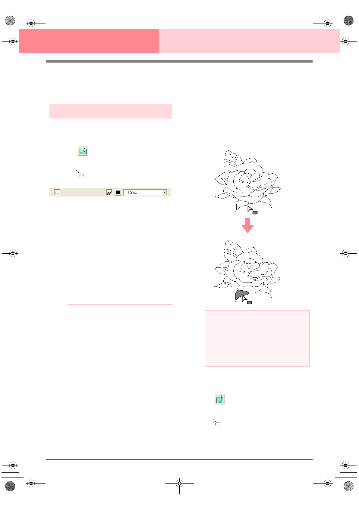
PeDesignV6Eng.book Page 84 Thursday, July 8, 2004 11:59 AM
Design Center Stage 4 (Sew Setting Stage)
Applying Sewing Attributes to Lines and
Regions
3. Click the enclosed region where you want to
Region sewing
■ Applying sewing attributes to
regions
1. Click on the Tool Box.
→ The shape of the pointer changes to
, and the Sewing Attributes bar ap-
pears similar to the one shown below.
apply the sewing attributes.
→ “Marching lines” appear around the se-
lected region, and the color and sew type
selected on the Sewing Attributes bar are
applied to the region.
2. If necessary, change the color and sew type.
b Memo:
• You can change the color and sew type
either before or after applying sewing
attributes to the region. For more details
on changing these settings, refer to “Color”
on page 89 and “Sew type” on page 89.
• You can also use the settings in the
Sewing Attribute Setting
define other attributes of the sew type. (For
more details, refer to “Specifying sewing
attributes” on page 89.) If you do not
change these settings at this time, the
current settings will be applied, however
you can modify them later.
dialog box to
a Note:
If the attributes cannot be applied to a
region, go back to stage 3 (Figure Handle
stage) and make sure that region is closed.
Edit any broken lines with the Point Edit tool.
For details on editing the figure handle
image, refer to “Editing Points in Outlines” on
page 81.
■ Checking the sewing attributes of
a region
84
1. Click on the Tool Box.
→ The shape of the pointer changes to
.
Page 93
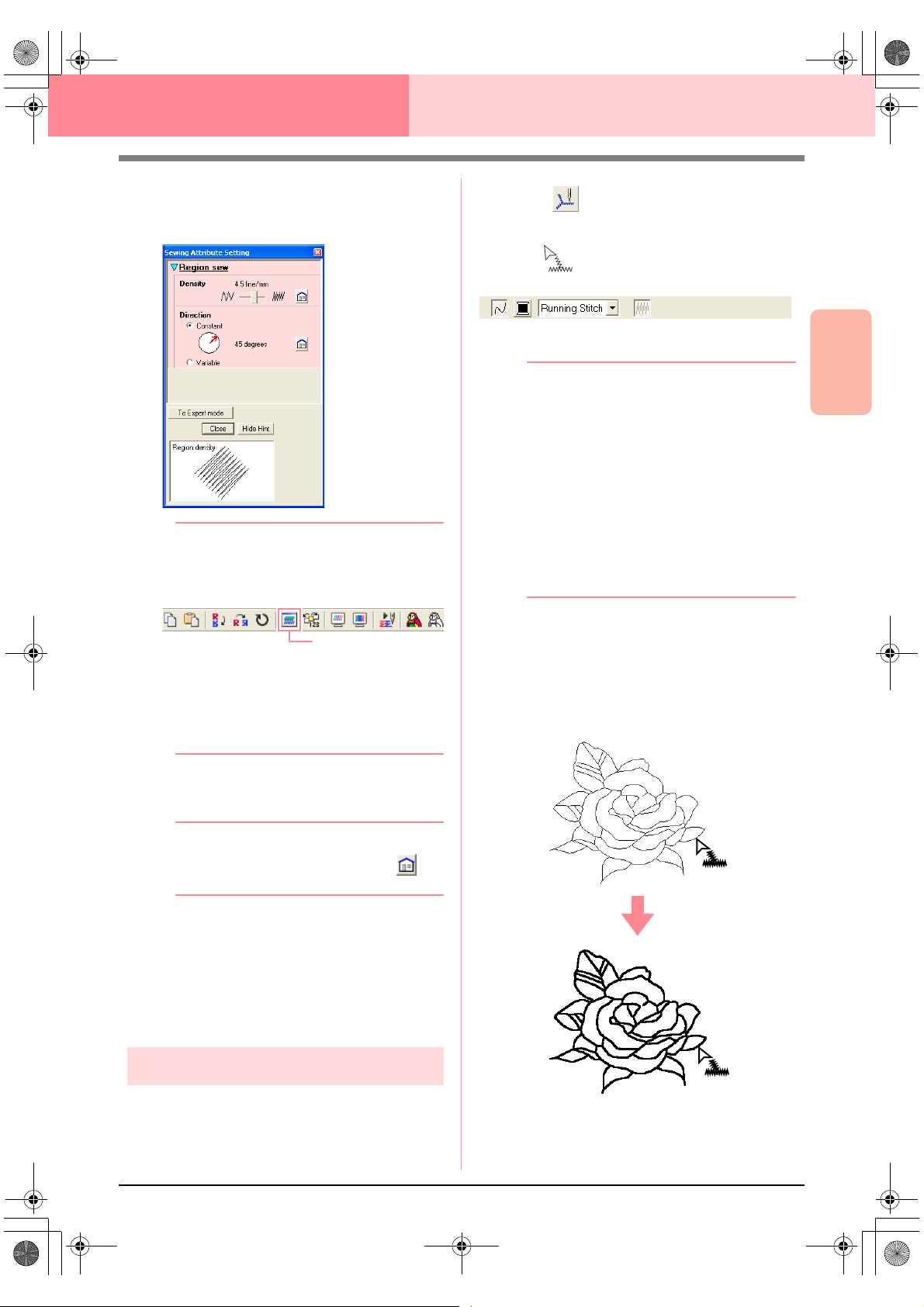
PeDesignV6Eng.book Page 85 Thursday, July 8, 2004 11:59 AM
Design Center Stage 4 (Sew Setting Stage)
2. Right-click a closed region.
→ The Sewing Attribute Setting dialog box
for the selected region appears.
b Memo:
• An alternate method is to select the menu
command
click the Toolbar button indicated below.
• The Sewing Attributes bar shows the color
and sew type for the selected region. You
can change the color and sew type at this
time. For more details on changing the
color and sew type, refer to “Color” on
page 89 and “Sew type” on page 89.
Sew – Setting Attribute
Sewing Attribute
, or
1. Click on the Tool Box.
→ The shape of the pointer changes to
, and the Sewing Attributes bar ap-
pears similar to the one shown below.
2. If necessary, change the color and sew type.
b Memo:
• You can change the color and sew type
either before or after applying sewing
attributes to the outline. For more details
on changing these settings, refer to “Color”
on page 89 and “Sew type” on page 89.
• You can also use the settings in the
Sewing Attribute Setting
define other attributes of the sew type. (For
more details, refer to “Specifying sewing
attributes” on page 89.) If you do not
change these settings at this time, the
current settings will be applied, however
you can modify them later.
3. Click the outline where you want to apply the
sewing attributes.
→ “Marching lines” appear along the select-
ed outline, and the color and sew type selected on the Sewing Attributes bar are
applied to the outline.
dialog box to
Design Center
Advanced Opreation
3. If necessary, change the settings in the
Sewing Attribute Setting dialog box.
b Memo:
To return to the default setting, click at
the right of the setting.
“Specifying sewing attributes” on page 89
c
4. To apply the new attributes to the region, click
each region where you want to apply the new
attributes.
5. Click Close to close the dialog box.
Line sewing
■ Applying sewing attributes to the
entire outline
85
Page 94

PeDesignV6Eng.book Page 86 Thursday, July 8, 2004 11:59 AM
Design Center Stage 4 (Sew Setting Stage)
■ Applying sewing attributes to a
portion of the outline
1. Click on the Tool Box.
→ The shape of the pointer changes to
, and the Sewing Attributes bar ap-
pears similar to the one shown below.
2. If necessary, change the color and sew type.
b Memo:
• You can change the sew type either before
or after applying sewing attributes to the
portion of the outline. For more details on
changing this setting, refer to “Sew type”
on page 89.
• You can also use the settings in the
Sewing Attribute Setting
define other attributes of the sew type. (For
more details, refer to “Specifying sewing
attributes” on page 89.) If you do not
change these settings at this time, the
current settings will be applied, however
you can modify them later.
dialog box to
→ “Marching lines” appear along the select-
ed portion of the outline, and the sew type
selected on the Sewing Attributes bar is
applied to the portion of the outline.
■ Checking the sewing attributes of
an outline
a Note:
The color cannot be set separately for a
portion of an outline. If you change the color,
the new color will be applied to the entire
outline of the portion that is clicked.
3. Click the portion of the outline where you want
to apply the sewing attributes.
1. To check the attributes of the entire outline,
click on the Tool Box.
→ The shape of the pointer changes to
.
To check the attributes of a portion of the
outline, click on the Tool Box.
→ The shape of the pointer changes to
.
2. Right-click the outline or a portion of the
outline.
86
Page 95

PeDesignV6Eng.book Page 87 Thursday, July 8, 2004 11:59 AM
Design Center Stage 4 (Sew Setting Stage)
→ The Sewing Attribute Setting dialog box
for the selected outline or portion of outline appears.
Using the Sewing Attributes bar
The Sewing Attributes bar, available in stage 4 (Sew
Setting stage), allows you to set the color and sew
type of region and outlines.
The sewing attributes that are available depend on
the tool selected in the Tool Box.
Example 1: When on the Tool Box is selected
Example 2: When or on the Tool Box is
selected
Design Center
Advanced Opreation
b Memo:
• An alternate method is to select the menu
command
click the Toolbar button indicated below.
• The Sewing Attributes bar shows the color
and sew type for the selected outline. At
this time, you can change the color and
sew type for the entire outline, or the sew
type for the portion of the outline. For more
details on changing the color and sew
type, refer to “Color” on page 89 and “Sew
type” on page 89.
Sew – Setting Attribute
Sewing Attribute
, or
3. If necessary, change the settings in the
Sewing Attribute Setting dialog box.
b Memo:
To return to the default setting, click at
the right of the setting.
“Specifying sewing attributes” on page 89
c
4. To apply the new attributes to the outline or
portion of outline, click the outline where you
want to apply the new attributes.
5. Click Close to close the dialog box.
When the pointer is positioned over a button or
selector in the Sewing Attributes bar, a label
indicating the name of that element appears.
!!sew4.bmp!!
Region sew: Switches
on/off sewing for the
region.
Line sew: Switches
on/off sewing for the
line.
Region color, Line
color: Click this button
to set the thread color
for lines or regions.
Region sew type,
Line sew type: Use
these selectors to set
the sew type for lines
or regions.
page
87
page
88
page
89
page
89
■ Region sew
Clicking this button switches on/off sewing for a
region.
b Memo:
•The
Region sew
when on the Tool Box is selected.
• When region sewing is switched off, the
region is not sewn (and you cannot set a
color or sew type).
button is available only
1. Click .
This button has two settings:
87
Page 96
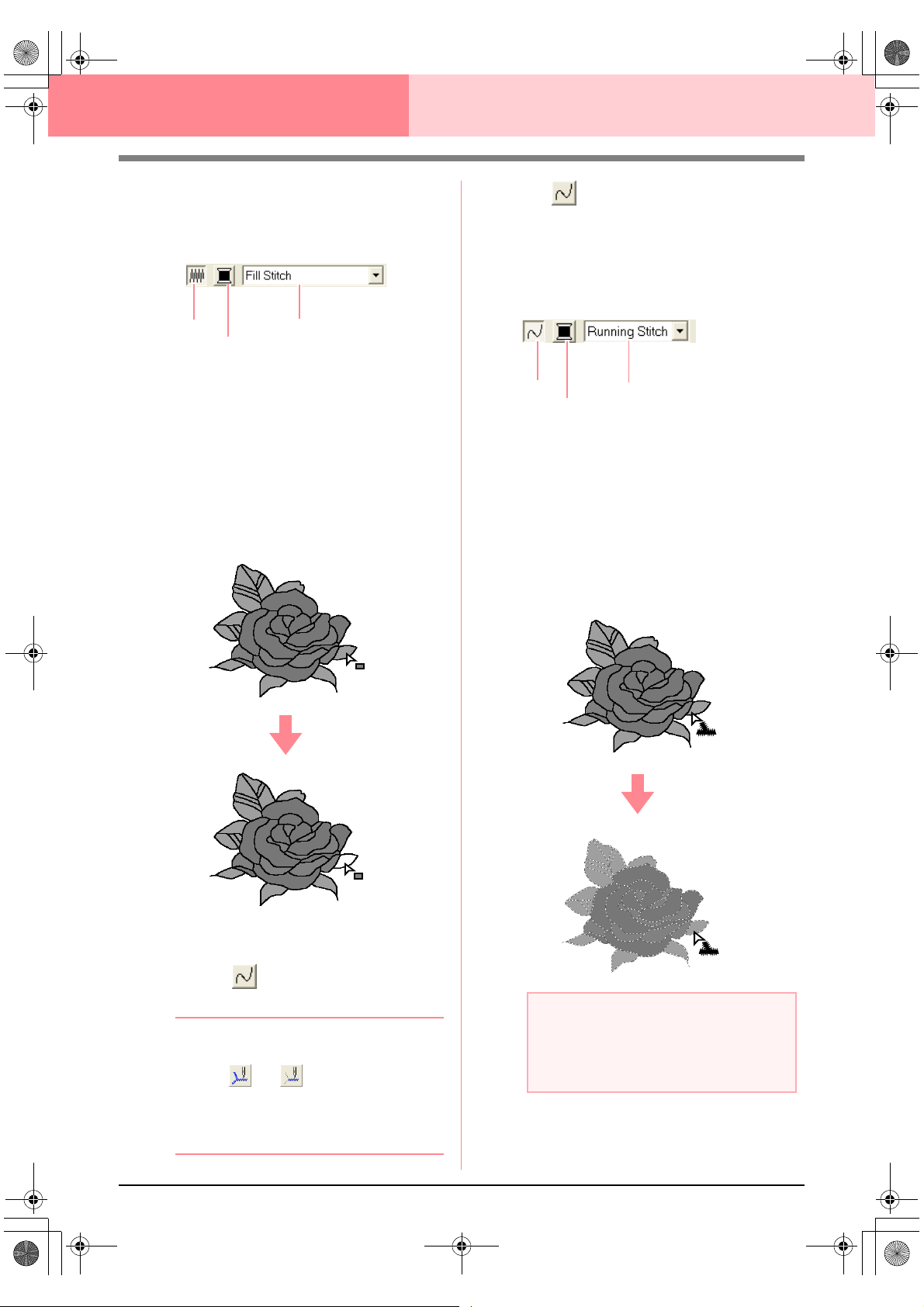
PeDesignV6Eng.book Page 88 Thursday, July 8, 2004 11:59 AM
Design Center Stage 4 (Sew Setting Stage)
On: The Region color button and the Region
sew type selector are displayed.
Off: The Region color button and the Region
sew type selector are not displayed.
Region sew
Region color
Region sew type
2. Click a region to apply the region sewing
attributes.
→ If the Region sew button has been
switched on, the color displayed in the
Region color button and the sew type
displayed in the Region sew type selector are applied to the region.
→ If the Region sew button has been
switched off, the color and sew type for
the region disappear.
1. Click .
This button has two settings:
On: The Line color button and the Line sew
type selector are displayed.
Off: The Line color button and the Line sew
type selector are not displayed.
Line sew
Line color
Line sew type
2. Click a line to apply the line sewing attributes.
→ If the Line sew button has been switched
on, the color displayed on the Line color
button and the sew type displayed in the
Line sew type selector are applied to the
line.
→ If the Line sew button has been switched
off, the line is replaced with a dotted line
and will not be sewn.
“Color” on page 89 and “Sew type” on
c
page 89
■ Line sew
Clicking this button switches on/off sewing for a line.
b Memo:
•The
Line sew
when or on the Tool Box is
selected.
• When line sewing is switched off, the line
is not sewn (and you cannot set its color or
sew type).
88
button is available only
a Note:
The color cannot be set separately for a
portion of the outline. If you change the
color, the new color will be applied to the
entire outline.
“Color” on page 89 and “Sew type” on
c
page 89
Page 97

PeDesignV6Eng.book Page 89 Thursday, July 8, 2004 11:59 AM
Design Center Stage 4 (Sew Setting Stage)
■ Color
Click this button to set the thread color for lines or
regions.
b Memo:
The
Color
Attributes bar when the
() or
turned on.
button appears in the Sewing
Line sew
1. Click the Color button.
→ A Line Thread Color dialog box similar to
the ones shown below appears.
Region sew
button ( ) has been
button
“Region sew” on page 87, “Line sew” on
c
page 88 and “Special colors” on page 170
■ Sew type
Region sew typeLine sew type
Use these selectors to set the sew type for lines or
regions.
b Memo:
The sew type selector appears in the Sewing
Attributes bar when the
() or
turned on.
Line sew
1. Click in a sew type selector.
→ The available settings appear.
Region sew
button ( ) has been
Region sew typeLine sew type
button
Design Center
Advanced Opreation
b Memo:
To view a list of only the thread colors, clear
View Details
the
check box.
2. From the Thread Chart selector, select a
thread color chart or a user thread chart.
For details on specifying a user thread
c
chart or for information on how machines
handle thread colors, refer to “Editing
User Thread Color Lists” on page 190.
3. From the list of thread colors, click the desired
color.
→ The new color is displayed on the Region
color button or Line color button.
b Memo:
• The name of the selected color appears at
the bottom of the dialog box.
• For details on the four buttons under the
list, refer to “Special colors” on page 170.
4. Click Close to set the color and to close the
dialog box.
5. Click the region or outline where you want to
apply the color setting.
2. Click the desired sew type.
→ The new setting appears in the selector.
3. Click the region or outline where you want to
apply the sew type setting.
“Region sew” on page 87 and “Line sew”
c
on page 88
Specifying sewing attributes
Various sewing attributes for lines and regions can
be set in the Sewing Attribute Setting dialog box.
Toolbar button:
1. Click in the Toolbar
→ The Sewing Attribute Setting dialog box
appears.
b Memo:
The region sew attributes appear in the
Sewing Attribute Setting
on the Tool Box is selected. The line
sew attributes appear in the
Attribute Setting
on the Tool Box is selected.
dialog box when or
dialog box when
Sewing
89
Page 98

PeDesignV6Eng.book Page 90 Thursday, July 8, 2004 11:59 AM
Design Center Stage 4 (Sew Setting Stage)
Beginner mode:
For line sewing
Expert mode:
For line sewing
For region sewing
For region sewing
b Memo:
• Settings that cannot be selected in
Beginner mode are retained from the
previous setting in Expert mode.
• To hide the preview box, click
To display the preview box, click
.
Hint
When the
the preview box is displayed, allowing you
to view a stitching sample when the pointer
is moved over the setting. The preview box
shows the setting changes that you make.
Hide Hint
button is displayed,
Hide Hint
Show
3. If necessary, change the sewing attributes
displayed under Line Sew or Region Sew.
b Memo:
• In some cases, you may need to scroll
through the settings, or resize the dialog
box by dragging one of its corners in order
to view all of the sewing attributes.
• The method for entering settings varies
according to the attribute. When entering
numerical values in Expert mode, click the
arrow buttons to select the value or enter
the value directly. In Beginner mode, use
the slider to change the settings. If
appears, click the button to return to the
default setting.
.
b Memo:
• An alternate method is to select the menu
command
right-click a region or line.
• The sewing attributes displayed in the
dialog box depend on the selected sew
type.
2. To display only basic sewing attributes and
simpler settings, click To Beginner mode.
To display all of the sewing attributes and
settings available for the selected sew type,
click To Expert mode.
Sew – Setting Attribute
, or
For details on the different sewing
c
attributes and settings, refer to “Line
sewing attributes” on page 91 and
“Region sewing attributes” on page 91.
a Note:
All settings made in the dialog box are
retained and will be applied regardless of the
mode, until they are changed.
4. When the line sewing attributes are displayed,
click an outline to apply the line sewing
attributes to the outline.
When the region sewing attributes are
displayed, click a region to apply the region
sewing attributes to the region.
5. Click Close to close the dialog box.
90
Page 99

PeDesignV6Eng.book Page 91 Thursday, July 8, 2004 11:59 AM
Design Center Stage 4 (Sew Setting Stage)
■ Line sewing attributes
The available attributes differ depending on the selected sew type. In Beginner mode, not all of the following
attributes appear.
Zigzag stitch
Zigzag width
Density
Half Stitch
Running stitch
Run pitch
Run times
Sets the width of the zigzag.
Range: 1–10 mm (0.04–0.39 inch)
Default: 2.0 mm (0.08 inch)
Sets the number of lines per millimeter (inch).
Range: 1–7 lines per mm (25–178 lines per inch)
Default: 4.5 lines per mm (114 lines per inch)
Sets half stitching on or off.
If one side of the zigzag stitching is dense, a half stitch could
be sewn automatically to provide a more even density.
Default: Off
Sets the pitch of the line sewing.
Range: 1–10 mm (0.04–0.39 inch)
Default: 2.0 mm (0.08 inch)
Sets the number of times that the border will be sewn.
Range: 2, 4, 6
Default: 2
On:
Off:
Design Center
Advanced Opreation
■ Region sewing attributes
The available attributes differ depending on the selected sew type. In Beginner mode, not all of the following
attributes appear.
Satin stitch
Sets underlay stitching on or off. Try to use underlay stitching for wide areas, in order to pre-
Under sewing
Density
Gradation
Direction
Half Stitch
vent shrinking during stitching. Depending on the shape of the region, however, it may not be
possible to select this setting.
On: Underlay stitching will be sewn.
Off: Underlay stitching will not be sewn.
Sets the number of lines per millimeter.
Range: 1–7 lines per mm (25–178 lines per inch)
Default: 4.5 lines per mm (114 lines per inch)
Sets the density gradation setting on or off.
Available when the type of sewing direction is set to Constant.
Click Pat tern to set the gradation pattern.
Default: Off
For details on this attribute, refer to“Creating a gradation” on page 96.
[Type] Specifies the type of sewing direction.
Constant: Sews at a fixed angle. The angle is specified by the angle setting.
Variable: Varies the sewing direction according to the object being sewn.
[Angle] Specifies the sewing angle.
Available only when the type sewing direction is
set to Constant.
Range: 0–359 degrees
Default: 45 degrees
Sets half stitching on or off.
Available when the type of sewing direction is set to Vari-
able.
If one side of the satin stitching is dense, a half stitch could
be sewn automatically to provide a more even density.
Default: Off
On:
Off:
180°
135°
225°
90°
270°
45°
0°
315°
91
Page 100
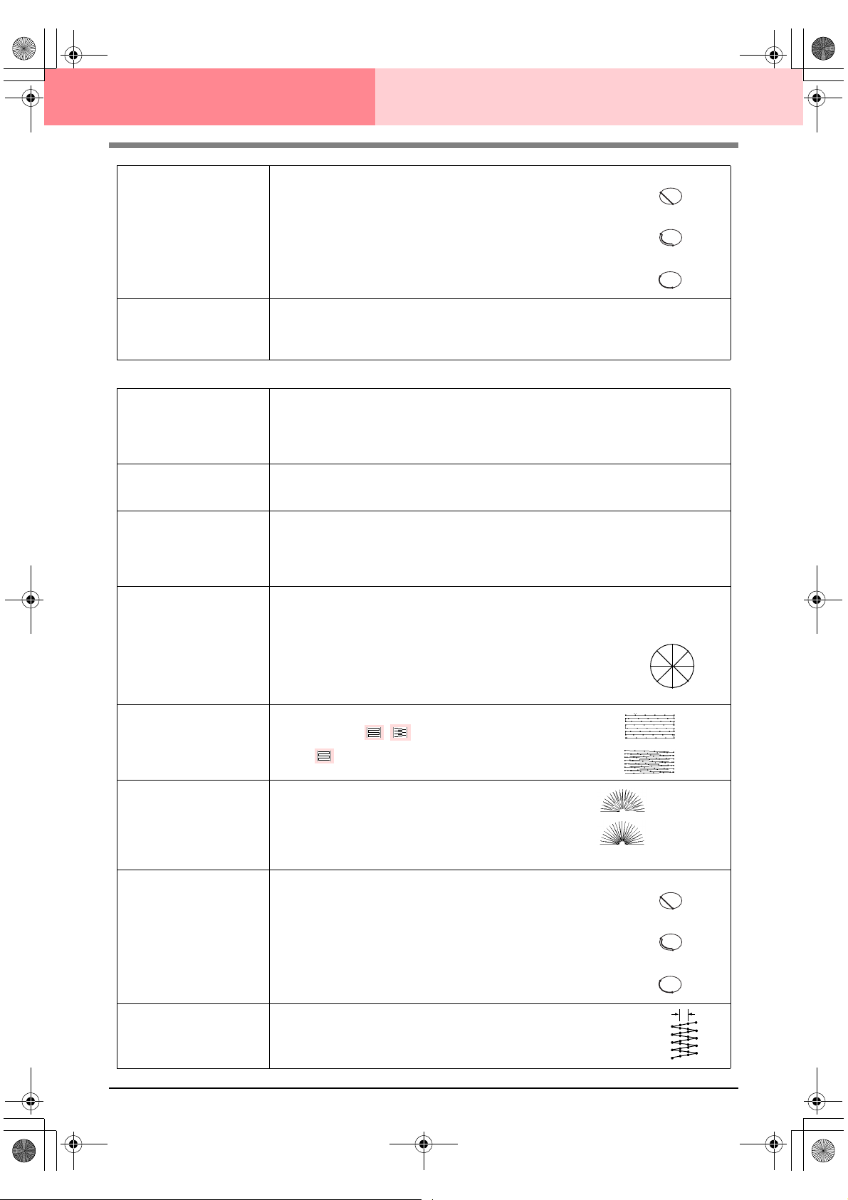
PeDesignV6Eng.book Page 92 Thursday, July 8, 2004 11:59 AM
Design Center Stage 4 (Sew Setting Stage)
Running Stitch Path
Pull Compensation
Fill stitch
Under sewing
Density
Gradation
Direction
Stitch Type
Sets the running path of the stitching.
Available when the type of sewing direction is set to Constant.
Available settings:
• Inside of region (shortest route)
• Along outline (along the inner side)
• Onto outline (on the outline)
The inside of region setting is available only when the Gradation
check box is cleared.
Default: Inside of region
Lengthens the sewing region in the stitch pattern’s sewing direction to prevent pattern shrinkage during sewing.
Range: 0–2 mm (0.00–0.08 inch)
Default: 0.0 mm (0.00 inch)
Sets underlay stitching on or off. Try to use underlay stitching for wide areas, in order to prevent shrinking during stitching. Depending on the shape of the region, however, it may not be
possible to select this setting.
On: Underlay stitching will be sewn.
Off: Underlay stitching will not be sewn.
Sets the number of lines per millimeter.
Range: 1–7 lines per mm (25–178 lines per inch)
Default: 4.5 lines per mm (114 lines per inch)
Sets the density gradation setting on or off.
Available when the type of sewing direction is set to Constant.
Click Pat tern to set the gradation pattern and its density.
Default: Off
For details on this attribute, refer to“Creating a gradation” on page 96.
[Type] Specifies the type of sewing direction.
Constant: Sews at a fixed angle. The angle is specified by the angle setting.
Variable: Varies the sewing direction according to the object being sewn.
[Angle] Specifies the sewing angle.
Available only when the sewing direction type is
set to Constant.
Range: 0–359 degrees
Default: 45 degrees
Specifies the shape of stitching on the edges.
Available settings: ,
Default:
Inside of region:
Along outline:
Onto outline:
90°
270°
45°
315°
135°
180°
225°
0°
Half Stitch
Running Stitch Path
Step Pitch
92
Sets half stitching on or off.
Available when the type of sewing direction is set to Vari-
able.
If one side of the fill stitching is dense, a half stitch could be
sewn automatically to provide a more even density.
Default: Off
Sets the running path of the stitching.
Available when the type of sewing direction is set to Constant.
Available settings:
• Inside of region (shortest route)
• Along outline (along the inner side)
• Onto outline (on the outline)
The inside of region setting is available only when the Gradation
check box is cleared.
Default: Inside of region
Sets the pitch of the stitching.
Range: 1–10 mm (0.04–0.39 inch)
Default: 4.0 mm (0.16 inch)
On:
Off:
Inside of region:
Along outline:
Onto outline:
Step pitch
 Loading...