

Brother 929D Owner's Manual
HANDBOOK FOR COMPACT
OVERLOCK MACHINE
MANUAL DE INSTRUCCIONES DE LA
MAQUINA COMPACTA OVERLOCK
5
4
4
4
4
5
5
5

"IMPORTANT SAFETY INSTRUCTIONS"
When using the sewing machine, basic safety precautions should always be followed,
including the following.
"Read all instructions before using."
DANGER – To reduce the risk of electric shock.
1. The sewing machine should never be left unattended when plugged in. Always unplug this sewing machine
from the electrical outlet immediately after using and before cleaning.
2. Always unplug before relamping. Replace bulb with same type rated 15 watts.
WARNING – To reduce the risk of burns, fire, electric shock, or injury to persons.
1. Do not allow to be used as a toy. Close attention is necessary when the sewing machine is used by or near
children.
2. Use this sewing machine only for its intended use as described in this manual. Use only accessories
recommended by the manufacturer as contained in this manual.
3. Never operate this sewing machine if it has a damaged cord or plug, if it is not working properly, if it has been
dropped or damaged, or dropped into water. Return the sewing machine to the nearest authorized dealer
or service center for examination, repair, electrical or mechanical adjustment.
4. Never operate the sewing machine with any air openings blocked. Keep ventilation openings of the sewing
machine and foot controller free from the accumulation of lint, dust, and loose cloth.
5. Never drop or insert any object into any openings.
6. Do not use outdoors.
7. Do not operate where aerosol (spray) products are being used or where oxygen is being administered.
8. To disconnect, turn the main switch to the symbol “O” position which represents off, then remove plug from
outlet.
9. Do not unplug by pulling on cord. To unplug, grasp the plug, not the cord.
10. Keep fingers away from all moving parts. Special care is required around the sewing machine needle.
11. Always use the proper needle plate. The wrong plate can cause the needle to break.
12. Do not use bent needles.
13. Do not pull or push fabric while stitching. It may deflect the needle causing it to break.
14. Switch the sewing machine to the symbol “O” position when making any adjustments in the needle area, such
as threading needle, changing needle, or changing presser foot, and the like.
15. Always unplug the sewing machine from the electrical outlet when removing covers, lubricating, or when
making any other user servicing adjustments mentioned in the instruction manual.
CA UTION – This appliance has a polarized plug (one blade wider than the other) to reduce the
risk of electric shock, this plug is intended to fit in a polarized outlet only one way.
If the plug does not fit fully in the outlet, reverse the plug.
If it still does not fit. Contact a qualified electrician to install the proper outlet.
Do not modify the plug in any way.
"SA VE THESE INSTRUCTIONS"
"This sewing machine is intended for household."
• When leaving this sewing machine unattended,
the mains switch of the machine must be switched
off or the plug must be removed from the socketoutlet.
• When servicing the sewing machine, or when
removing covers or changing lamps, the machine or the electrical set must be disconnected
from the supply by removing the plug from the
socket-outlet.
FOR USERS IN THE UK, EIRE, MALTA AND CYPRUS ONLY.
If your sewing machine is fitted with a 3 pin non rewireable BS plug then please read the following.
IMPORTANT
If the available socket outlet is not suitable for the
plug supplied with this equipment, it should be cut off
and an appropriate three pin plug fitted. With alternative plugs an approved fuse must be fitted in the plug.
NOTE: The plug severed from the mains lead must
be destroyed as a plug with bared flexible cords is
hazardous if engaged in a live socket outlet. In the
event of replacing the plug fuse, use a fuse approved
by ASTA to BS 1362, i.e. carrying the
ASA
mark, rating
as marked on plug.
Always replace the fuse cover, never use plugs with
the fuse cover omitted.
WARNING: DO NOT CONNECT EITHER WIRE
TO THE EARTH TERMINAL WHICH IS MARKED
WITH THE LETTER ‘E’, BY THE EARTH SYMBOL
OR COLOURED GREEN OR YELLOW.
The wires in this mains lead are coloured in accordance with the following code:
Blue Neutral
Brown Live
As the colours of the wiring in the mains lead of this
appliance may not correspond with the coloured
markings identifying the terminals in your plug, proceed as follows.
The wire which is coloured blue must be connected
to the terminal which is marked with the letter ‘N’ or
coloured black or blue.
The wire which is coloured brown must be connected
to the terminal which is marked with the letter ‘L’ or
coloured red or brown.

CONGRATULATIONS ON
CHOOSING THIS COMPACT
OVERLOCK MACHINE
FELICITACIONES POR HABER
ELEGIDO ESTA COMPACTA
MAQUINA OVERLOCK
Your machine is a high quality, easy-to-use
product. To fully enjoy all the features, we
suggest that you study this booklet.
If you need more information regarding the use
of your machine, your nearest authorized dealer
is always happy to be of service.
Enjoy yourself!
CAUTION!
WHEN THREADING, REPLACING NEEDLE
OR LIGHT BULB, BE SURE TO TURN OFF
THE MAIN POWER SWITCH OF THE MACHINE.
WHEN THE MACHINE IS NOT IN USE, IT IS
RECOMMENDED THAT THE ELECTRIC SUPPLY PLUG IS DISCONNECTED FROM THE
WALL SOCKET TO AVOID ANY POSSIBLE
HAZARDS.
Su máquina es de una eficacia y calidad excelentes; así pues, a fin de disfrutar completamente de todas las características incorporadas, le sugerimo estudie el manual.
Si se necesitara mayor información sobre el
uso de esta máquina, el proveedor autorizado
más cercano estará encantado de ofrecerle
sus servicios.
¡PRECAUCION!
ASEGURARSE DE QUE EL INTERRUPTOR
GENERAL DE LA MAQUINA ESTE APAGADO
CUANDO SE ENHEBRE, REEMPLACE LA
AGUJA O CAMBIE LA LAMPARITA.
CUANDO NO SE UTILICE LA MAQUINA, SE
RECOMIENDA QUE EL ENCHUFE ESTE DESCONECTADO DE LA RED DE LA CORRIENTE, A FIN DE EVITAR CUALQUIER PELIGRO.

Notes on the motor
NOTAS SOBRE EL
MOTOR
• The normal operating speed of this sewing ma-
chine is 1,300 stitches per minute, which is quite
fast compared to the normal operating speed of
300 to 800 stitches per minute for the ordinary
foot-operated sewing machine.
• The bearings in the motor are made of a special
sintered, oil-impregnated alloy mounted in oilsoaked felt to withstand long hours of continuous
operation.
• Continuous operation of the sewing machine can
cause heat to build in the motor area, but not
enough to adversely affect its performance.
It is important to keep fabric and paper away from
the ventilating holes on the back and sides of the
machine so air can get to these holes.
• When the motor is running, sparks can be seen
through the ventilating hole in the motor bracket
on the side opposite the hand wheel. These
sparks are produced by the carbon brushes and
the commutator, and are part of the machines
normal operation.
CAUTION
WHEN THREADING THE MACHINE, REPLACING A NEEDLE, OR WHEN THE MACHINE IS NOT IN USE, WE RECOMMEND
DISCONNECTING THE ELECTRIC SUPPLY
PLUG TO AVOID ANY POSSIBLE HAZARDS.
•
La velocidad normal de funcionamiento de esta
máquina de coser es de 1.300 puntadas por
minuto, lo que resulta bastante rápido comparado con la velocidad normal de 300 a 800 puntadas por minuto de las máquinas de coser normales que funcionan con pedal.
•
Los cojinetes del motor están hechos de una
aleación especial impregnada en aceite sintético
y montada en un fieltro impregnado en aceite,
para poder funcionar continuamente durante
muchas horas.
•
Un funcionamiento continuo de la máquina puede contribuir a calentar algo la máquina en la
zona del motor, pero no lo suficiente como para
alterar su rendimiento y funcionamiento.
Sin embargo, es menester mantener los orificios
de ventilación de la parte trasera y en los lados de
la máquina sin tapar con tejido o papel durante el
uso, para que el aire pueda circular por los
orificios.
•
Durante el funcionamiento del motor, se pueden
ver chispas a través del orificio de ventilación de
la abrazadera del motor, en el lado contrario a la
ruedecilla. Estas chispas son producidas por las
escobillas de carbón que entran en contacto con
el conmutador, y forman parte del funcionamiento normal de la máquina.
PRECAUCION
Al enhebrar la máquina, cambiar una aguja o
al dejar la máquina sin usar, le recomendamos desenchufar la máquina para evitar
cualquier peligro de corto circuito.

Chapter 1
Chapter 2
Chapter 3
Chapter 4
Chapter 5
Chapter 6
Chapter 7
Chapter 8
Chapter 9
Chapter 10
Chapter 11
Chapter 12
Chapter 13
Chapter 14
Chapter 15
Chapter 16
Chapter 17
Chapter 18
Chapter 19
TABLE OF CONTENTS
Names of parts and their functions ............................................................................... 1
Accessories included with your serger ..................................................................................... 3
Needle ...................................................................................................................................... 5
Turning direction of motor ........................................................................................................ 7
Opening and closing the front cover ........................................................................................ 7
Operating .............................................................................................................................. 8
Powering the machine.............................................................................................................. 8
Electronic Display (Only for models installed with a 1-line LCD) ......................... 8
Language selection .................................................................................................................. 8
Removing the Bed Extension for Free-Arm Sewing ...........................................13
Removing the bed extension.................................................................................................. 13
Stitch Length...................................................................................................................... 14
Stitch Width ........................................................................................................................ 14
Instructions for the Differential Feed Mechanism
(Models with Differential Feed) ..................................................................................... 15
Before Threading .............................................................................................................. 18
Preparation before threading ................................................................................................. 18
How to use the thread spool cap............................................................................................ 19
How to use the thread net ...................................................................................................... 19
Tension release button........................................................................................................... 19
Before threading..................................................................................................................... 20
Threading the upperlooper ..................................................................................................... 21
Threading the lowerlooper...................................................................................................... 23
Threading the right needle (on Two-needle models).............................................................. 25
Threading the left needle .......................................................................................................27
Comparison Chart of Sewing Materials, Threads and Needles............................ 29
Thread Tension.................................................................................................................. 31
Chart of Thread Tension Adjustment .......................................................................... 33
Test-sewing ........................................................................................................................ 37
Chaining-off ............................................................................................................................ 38
Sewing ................................................................................................................................. 39
To start sewing ....................................................................................................................... 39
To remove work...................................................................................................................... 40
If threads break during sewing ............................................................................................... 40
To sew heavy materials..........................................................................................................41
To sew fine materials ............................................................................................................. 41
Presser foot pressure ............................................................................................................. 42
Troubleshooting................................................................................................................ 43
Stitch Selection ................................................................................................................. 45
Narrow overlock stitch/rolled edge stitch................................................................................ 46
Chart of Narrow Overlock/Rolled Edge Stitch .......................................................... 49
Examples of Sewing Applications for this Serger ................................................... 51
Blind stitching with blind stitch presser foot............................................................................ 52
Flatlock stitching with blind stitch presser foot ....................................................................... 54
Pin tuck stitching with blind stitch presser foot ....................................................................... 56
Decorative stitching ................................................................................................................ 58
Upper Knife and Lower Knife ........................................................................................ 59
Retracting upper knife ............................................................................................................ 59
Replacing the knives .............................................................................................................. 60
Oiling .................................................................................................................................... 61
Changing the Light Bulb ................................................................................................. 62
Machine Specifications ................................................................................................... 63
SETTING RECORD............................................................................................................ 64
CONTENTS
TABLE OF
Chapter
1
Chapter
2
Chapter
3
Chapter
4
Chapter
5
Chapter
6
Chapter
7
Chapter
8
Chapter
9
Chapter
10
Chapter
11
Chapter
12
Chapter
13
Chapter
14
Chapter
15
Chapter
16
Chapter
17
Chapter
18
Chapter
19

INDICE
Capítulo 1 Nombres de las partes y sus funciones
Accesorios incluidos con la máquina de coser ........................................................................ 3
Aguja ........................................................................................................................................ 5
Para cambiar la dirección del motor......................................................................................... 7
Abre y cierre de la tapa delantera ............................................................................................ 7
Capítulo 2 Funcionamiento
Encendido de la máquina.........................................................................................................8
.................................................................................................................. 8
....................................................................... 1
Pantalla electrónica
(Sólo para los modelos provistos con pantalla de una línea)
Selección de idioma ................................................................................................................. 8
................................ 8
Extraiga el suplemento para la mesa para realizar la costura sin brazo ..........
Extraiga el suplemento para la mesa ..................................................................................... 13
Capítulo 3 Largo de puntada
Ancho de puntada
.............................................................................................................. 14
............................................................................................................ 14
Capítulo 4 Instrucciones para el mecanismo de alimentación con diferencial
(Modelos con alimentador diferencial)
Capítulo 5 Antes del enhebrado
Preparación antes del enhebrado .......................................................................................... 18
Como utilizar el tope del carrete............................................................................................. 19
Como utilizar la malla para hilo .............................................................................................. 19
Botón de liberación de la tensión ........................................................................................... 19
Antes de enhebrar.................................................................................................................. 20
Enhebrado del áncora superior .............................................................................................. 21
Enhebrado del áncora inferior ................................................................................................ 23
Enhebrado de la aguja derecha (los modelos de dos agujas) ............................................... 25
Enhebrado de la aguja izquierda ........................................................................................... 27
........................................................................................................ 18
Capítulo 6 Tabla de relación entre los distintos tejidos, hilos y agujas
Capítulo 7 Tensión del hilo
................................................................................................................. 31
Capítulo 8 Tabla de ajuste de tensión de los hilos
Capítulo 9 Costura de prueba
Cadeneta................................................................................................................................ 38
Capítulo 10 Costura
Para empezar a coser ............................................................................................................39
Para retirar el trabajo.............................................................................................................. 40
Si el hilo se rompe al coser ....................................................................................................40
Para coser tejidos gruesos..................................................................................................... 41
Para coser tejidos finos .......................................................................................................... 41
Presión del prensatelas.......................................................................................................... 42
................................................................................................................................39
Capítulo 11 Guía de localización de fallas
............................................................................................................ 37
........................................................................................ 44
Capítulo 12 Selección de las distintas puntadas
Puntada overlock estrecha/puntada de borde enrollado........................................................ 46
Capítulo 13 Tabla para puntadas overlock estrechas/de borde enrollado
....................................................................... 15
................................ 30
...................................................................... 33
............................................................................ 45
.............................. 50
Capítulo 14 Ejemplos de aplicaciones de costuras para estas máquinas de coser
Puntadas invisibles con prensatelas multipropósito............................................................... 52
Costura Overlock plana con prensatelas multipropósito ........................................................ 54
Costuras de pliegues pequeños con prensatelas multipropósito ........................................... 56
Puntadas decorativas............................................................................................................. 58
Capítulo 15 Cuchillas superior e inferior
Meter la cuchilla superior ....................................................................................................... 59
Cambio de las cuchillas.......................................................................................................... 60
Capítulo 16 Engrasado
........................................................................................................................... 61
Capítulo 17 Cambio de la bombilla de luz
Capítulo 18 Especificaciones técnicas de la máquina
Capítulo 19 NOTAS DE AJUSTES
....................................................................................................... 65
.......................................................................................... 59
........................................................................................ 62
.................................................................. 63
13
............. 51
CONTENTS
TABLE OF
Names of parts and
their functions
1
A
5
0
4
6
3
2
BC
5
5
4
4
Nombres de las partes
y sus funciones
J
G
F
5
5
4
4
D
E
1
2
3
4
5
6
7
8
9
Chapter
Chapter
Chapter
Chapter
Chapter
Chapter
Chapter
Chapter
Chapter
7
8
L
K
T
O
9
E
P
Q
SR
HI
M
N
10
11
12
13
14
15
16
17
18
Chapter
Chapter
Chapter
Chapter
Chapter
Chapter
Chapter
Chapter
Chapter
1
19
Chapter

CONTENTS
TABLE OF
Chapter
1
1 Thread tree
2 Handle
3 Presser foot pressure adjustment screw
4 Spool pin
5 Spool support
6 Thread take-up cover
7 Needles
8 Upper knife
9 Presser foot
0 Material plate cover
A Spool stand (thread tree support)
B Left needle thread tension dial
C Right needle thread tension dial
D Presser foot lifting lever
E Hand wheel
F Upperlooper thread tension dial
G Lowerlooper thread tension dial
H Front cover
I Material slide plate (for overlock stitch)
J Main power switch and light switch
K Stitch length adjustment dial
L Differential feed ratio adjustment lever
M Lowerlooper threading lever
N Stitch finger
O Stitch width lever
P Upperlooper
Q Lowerlooper
R Free-arm cover
S Bed extension
T Knife lever
1
Arbol del hilo
2
Asa
3
Tornillo de ajuste de la presión del prensatelas
4
Portabobina
5
Soporte de la bobina
6
Tapa de toma de hilo
7
Agujas
8
Cuchilla superior
9
Prensatelas
0
Tapa de tejido
A
Filete para la canilla (soporte del árbol del hilo)
B
Disco de tensión del hilo de la aguja izquierda
C
Disco de tensión del hilo de la aguja derecha
D
Palanca de levantamiento del prensatelas
E
Ruedecilla
F
Disco de tensión del hilo del áncora superior
G
Disco de tensión del hilo del áncora inferior
H
Tapa delantera
I
Placa de deslice del tejido (para puntadas
Overlock)
J
Interruptor de alimentación principal e interruptor
de luz
K
Disco de ajuste del largo de las puntadas.
L
Palanca diferencial de ajuste de la velocidad de
alimentación
M
Palanca de enhebrado del áncora inferior
N
Uñeta de puntadas
O
Palanca de anchura de las puntadas.
P
Ancora superior
Q
Ancora inferior
R
Cubierta del brazo
S
Suplemento para la mesa
T
Palanca de cuchilla
2
3
4
5
6
7
8
9
10
11
12
13
14
15
Chapter
Chapter
Chapter
Chapter
Chapter
Chapter
Chapter
Chapter
Chapter
Chapter
Chapter
Chapter
Chapter
Chapter
2
16
17
18
19
Chapter
Chapter
Chapter
Chapter
Accessories included
with your serger
1 X77871-000
Accesorios incluidos con
la máquina de coser
3 X75902001
7 X75906001
CONTENTS
TABLE OF
Chapter
1
Chapter
2
Chapter
3
Chapter
4
2 122991002
OPTION / OPTATIVO
0 X76590002
4 X75904000
5 X77260000
6 X75437001
A X77767-001
8 X77128001
9 X75917001
B X76663001
5
6
7
8
9
10
11
12
13
Chapter
Chapter
Chapter
Chapter
Chapter
Chapter
Chapter
Chapter
Chapter
;, A, B OPTION
3
;, A, B
OPTATIVO
14
15
16
17
18
19
Chapter
Chapter
Chapter
Chapter
Chapter
Chapter

The number represents the parts code
1 Soft cover
2 Accessory bag
3 Tweezers
4 Thread net
Two-needle models (4)
One-needle models (3)
5 Thread spool cap
Two-needle models (4)
One-needle models (3)
6 Screw driver
7 Cleaning brush
Hexagonal (Allen) wrench (on Two-needle mod-
8
els)
9 Needle set: SCHMETZ 130/705M
80/12: 2 pcs.
90/14: 2 pcs.
; Blind stitch foot (Option)
A Trim trap (Option)
B Tape presser foot (Option)
Foot controller: J01780051 (110/120V Area)
J01590051 (220/240V Area)
J01664051 (U.K.)
J01665051 (Australia, New Zealand)
XA1347051 (Germany)
El número corresponde al código de los elementos
1
Funda
2
Bolsa de accesorios
3
Pinzas
4
Malla
Modelos de dos agujas (4)
Modelos de una aguja (3)
5
Tope del carrete
Modelos de dos agujas (4)
Modelos de una aguja (3)
6
Destornillador
7
Cepillo limpiador
8
Llave de tuerca hexagonal (Allen) (Modelos de
das agujas)
9
Juego de agujas: SCHMETZ 130/705M
80/12: 2 unidades
90/14: 2 unidades
;
Prensatelas para puntadas invisibles (Optativo)
A
Orificio de corte (Optativo)
B
Prensatelas para cintas (Optativo)
Pedal: J01780051 (zona con 110/120V)
J01590051 (zona con 220/240V)
J01664051 (Reino Unido)
J01665051 (Australia, Nueva Zelanda)
XA1347051 (Alemania)
CONTENTS
TABLE OF
Chapter
1
Chapter
2
Chapter
3
Chapter
4
Chapter
5
Chapter
6
Chapter
7
Chapter
8
Chapter
9
Chapter
10
11
12
13
14
15
16
17
18
19
Chapter
Chapter
Chapter
Chapter
Chapter
Chapter
Chapter
Chapter
Chapter
4
Needle
6
7
5
This machine uses a standard home sewing machine needle.
The recommended needle is SCHMETZ 130/705H.
Aguja
Está máquina funciona con una aguja normal para
máquinas domésticas. Así mismo, se recomienda el
uso de una aguja SCHMETZ 130/705H.
CONTENTS
TABLE OF
Chapter
1
Chapter
2
Chapter
3
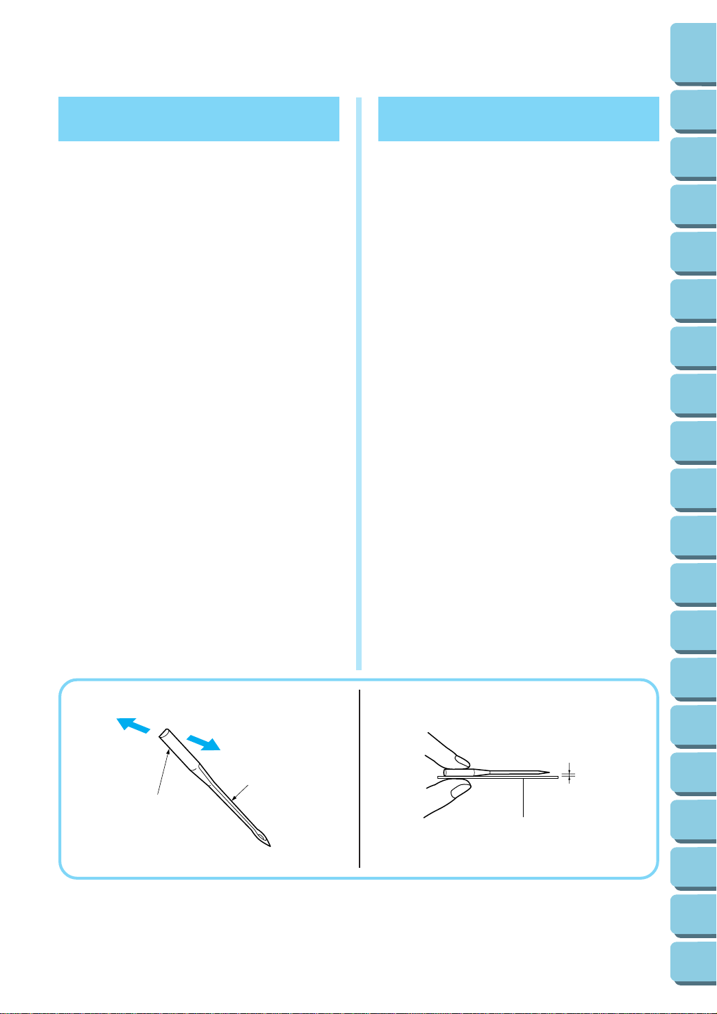
To remove the needle
(1)Turn the main power switch to the OFF position.
(2)Turn the hand wheel counter-clockwise by hand
until the needle is at its highest position.
(3)Loosen the needle set screw with hexagonal
wrench and remove the needle.
1 Back
2 Front
3 Flat side
4 Groove
To insert the needle
(1)Turn the main power switch to the OFF position.
(2)Turn the hand wheel until the needle bar is at its
highest position.
(3)Hold the needle with its flat side away from you
and insert it up as far as it will go.
(4) Tighten the needle set screw securely with the
hexagonal wrench.
5 Place the needle on its flat side and check
to see if the space is parallel.
6 Flat side
7 (needle-plate, glass, etc.)
Para sacar la aguja
(1)Apague el interruptor principal (posición OFF).
(2)Gire la ruedecilla a mano, en contra de las mane-
cillas del reloj hasta que la aguja alcance la
posición más elevada.
(3)Afloje el tornillo de instalación de la aguja con la
llave hexagonal y saque la aguja.
1
Parte trasera
2
Parte delantera
3
Parte llana
4
Canal
Para introducir la aguja
(1)Apague el interruptor principal (póngalo en OFF).
(2)Gire la ruedecilla hasta que la barra de la aguja
alcance la posición más alta.
(3)Sujete la aguja con la parte curvada de cara a Vd.
e insértela hacia arriba hasta el tope.
(4)Vuelva a apretar firmemente el tornillo de instala-
ción de la aguja con la llave hexagonal.
5
Coloque la aguja en su parte llana y compruebe que el espacio sea paralelo.
6
Parte llana
7
Placa de aguja (Vidrio, etc.)
4
5
6
7
8
9
10
11
12
Chapter
Chapter
Chapter
Chapter
Chapter
Chapter
Chapter
Chapter
Chapter
5
1
3
2
4
13
14
15
16
17
18
19
Chapter
Chapter
Chapter
Chapter
Chapter
Chapter
Chapter
NOTE:
Two-needle models
• On two-needle models, we suggest you hold the
two needles with one hand and then insert them
both at the same time.
• If the needles have been inserted correctly, the
right needle should be set slightly lower than the
left one.
CAUTION
The needle set screw holds both needles.
Keep this in mind when you loosen the set
screw to exchange one or both needles.
8 Needle set screw
9 Tighten
0 Loosen
A Hexagonal wrench
NOTA:
Modelos de dos agujas
•
En los modelos de dos agujas, le sugerimos
sujetar ambas agujas en una sola mano e insertarlas simultáneamente.
•
Si las agujas fueron introducidas correctamente,
la aguja de derecha debería quedar un poco más
abajo de la izquierda.
PRECAUCION
El tornillo de instalación de las agujas sujeta
ambas agujas. No se lo olvide al aflojar
dicho tornillo para cambiar una o ambas
agujas.
8
Tornillo de instalación de las agujas
9
Apretar
0
Aflojar
A
Llave de tuerca hexagonal
CONTENTS
TABLE OF
Chapter
1
Chapter
2
Chapter
3
Chapter
4
Chapter
5
Chapter
6
Chapter
7
Chapter
8
8
One-needle models
B Needle set screw
C Tighten
D Loosen
E Hexagonal wrench
9
0
A
B
Modelos de una aguja
B
Tornillo de instalación de las agujas
C
Apretar
D
Aflojar
E
Llave de tuerca hexagonal
C
D
9
10
11
12
13
14
15
16
17
Chapter
Chapter
Chapter
Chapter
Chapter
Chapter
Chapter
Chapter
Chapter
E
6
18
19
Chapter
Chapter
Turning direction of motor
• The motor and hand wheel of this machine turn in
a counterclockwise direction (direction of arrow).
This is the same direction as an ordinary home
sewing machine.
1 Hand wheel
Para cambiar la dirección
del motor
•
El motor y la ruedecilla de esta máquina funcionan en el sentido contrario al de las manecillas
del reloj (dirección de la flecha), como es el caso
con la mayoría de las máquinas de coser domésticas.
1
Ruedecilla
CONTENTS
TABLE OF
Chapter
1
Chapter
2
Chapter
3
Chapter
4
Chapter
5
Chapter
6
Chapter
7
Chapter
8
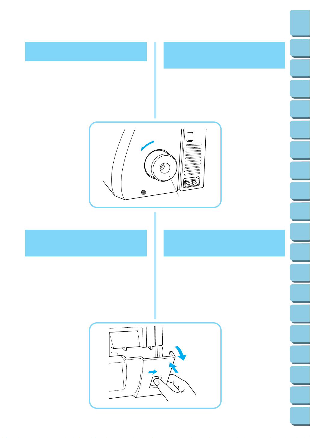
Opening and closing the
front cover
It is necessary to open the front cover when threading this machine.
NOTE:
For your safety, make sure that the front cover is
closed when operating the machine.
1
Abre y cierre de la tapa
delantera
Es necesario abrir la tapa delantera para enhebrar la
máquina.
NOTA:
Para su propia seguridad, averigue siempre que la
tapa delantera esté bien cerrada antes de hacer
funcionar la máquina.
9
10
11
12
13
14
15
16
17
Chapter
Chapter
Chapter
Chapter
Chapter
Chapter
Chapter
Chapter
Chapter
7
18
19
Chapter
Chapter
CONTENTS
TABLE OF
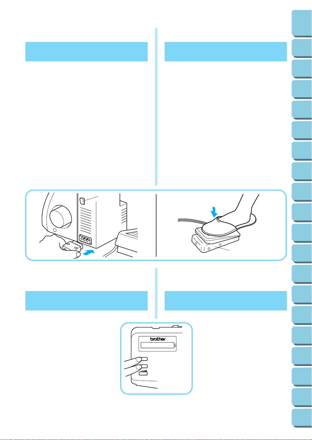
Operating
Powering the machine
Preparation
• Insert the three-pin plug into the socket on the
bottom right side of the machine. Insert the power
supply plug into a power outlet.
Main Power and Sewing Light Switch
This switch turns the power and sewing light on or off.
To turn on push toward “1” mark. To turn off push
toward “0” mark.
1 Main Power and Sewing Light Switch
Operation
When the pedal is pressed lightly, the machine runs
at a low speed. As the pedal is pressed further, the
machine will increase speed. When the pedal is
released, the machine stops.
2 Foot Controller: Model N
Note (For U.S.A. only):
This foot controller can be used for sewing machine
models 940D, 939D, 935D, 929D 925D, 925, 915D
and 915.
1
Funcionamiento
Encendido de la máquina
Preparación de la máquina
•
Introduzca el zócalo de tres puntas en el enchufe
que se encuentra abajo, en el lado derecho de la
máquina e inserte el zócalo de alimentación en
una toma de corriente.
Interruptor principal y de luz
Este interruptor permite apagar y encender la máquina así como la luz. Para encender, empuje hacia
la marca “1”; para apagar, póngalo en la marca “0”.
1
Interruptor principal y de luz
Funcionamiento
Al oprimir ligeramente el pedal, la máquina funcionará a baja velocidad. A medida que se apriete más, la
máquina incrementará su velocidad. La máquina se
parará tan pronto como se suelte el pedal.
2
Pedal
1
2
3
4
5
6
7
8
9
Chapter
Chapter
Chapter
Chapter
Chapter
Chapter
Chapter
Chapter
Chapter
Electronic Display
(Only for models installed with a
1-line LCD)
Language selection
(1)Turn the main power switch to the
OFF position.
(2)Turn the main power switch to the
ON position with pressing SELECT
key and INF key simultaneously.
(3)Press SELECT key until your pre-
ferred language is displayed.
(4)Turn the main power switch to the
OFF position with your preferred
language displayed.
(5)Your preferred language will be
selected when you turn the main
power switch to the ON position
again.
SELECT
INF
2
Pantalla electrónica
(Sólo para los modelos provistos
con pantalla de una línea)
Selección de idioma
(1)Ponga el interruptor de la alimenta-
ción principal en la posición OFF.
(2)Ponga el interruptor de la alimenta-
ción principal en la posición ON
mientras presiona simultáneamente la tecla SELECT y la tecla INF.
(3)Presione la tecla SELECT hasta
que se visualice el idioma que usted desee.
(4)Ponga el interruptor de la alimenta-
ción principal en la posición OFF
cuando se visualice el idioma que
usted desee.
(5) El idioma que usted desee se se-
leccionará cuando vuelva a poner
el interruptor de la alimentación
principal en la posición ON.
8
10
11
12
13
14
15
16
17
18
19
Chapter
Chapter
Chapter
Chapter
Chapter
Chapter
Chapter
Chapter
Chapter
Chapter
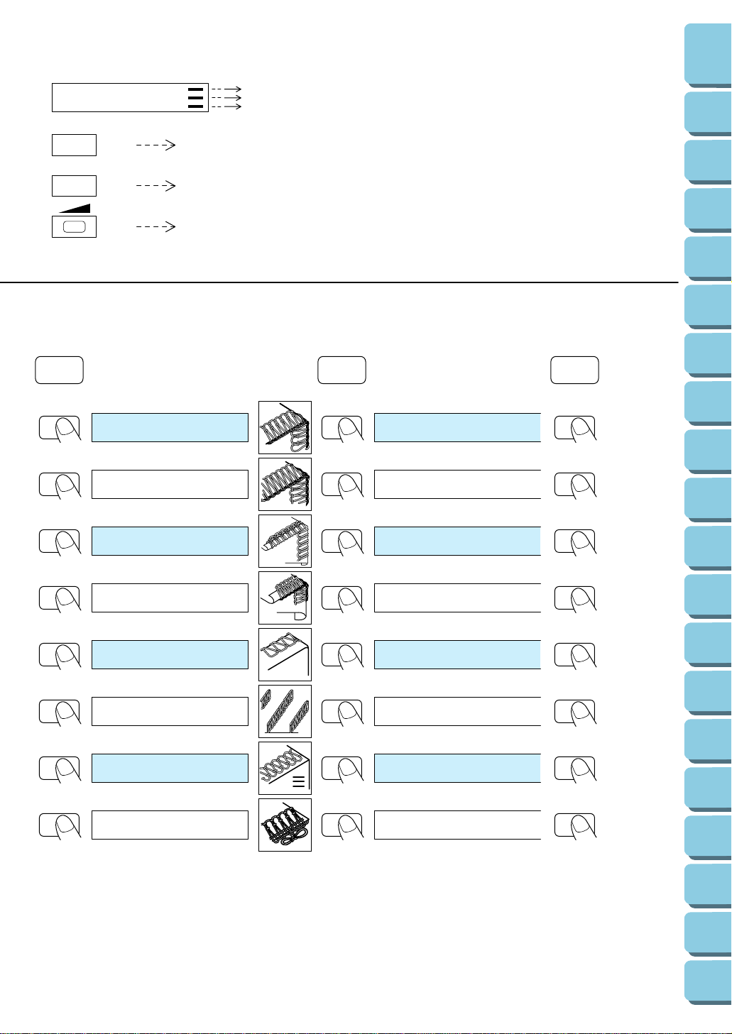
Electronic Display (Only for models installed with a 1-line LCD)
LCD Display Thickness of the fabric
Thick
LCD Display
SELECT
Stitch selection key
INF
Information key
Normal
Thin
Eight stitches can be chosen.
Information about the selected stitch, its operation
and the appropriate thread tension settings are
displayed.
CONTENTS
TABLE OF
Chapter
1
Chapter
2
Chapter
3
Contrast adjusting lever
NOTE: Polyester thread #60 is the standard thread type.
SELECT INF INF
Choose the desired stitch.
1) 4-OVERLOCK
12
2) 3-OVERLOCK
3) ROLLED EDGE
4) NARROW EDGE
The display’s contrast can be adjusted.
Stitch applications and
instructions are displayed.
4 THREADS INTERLO....
3 THREADS INTERLO.......
PROVIDES A DECORAT...
ALSO CALLED NARROW..
4
5
6
7
8
9
10
11
12
Chapter
Chapter
Chapter
Chapter
Chapter
Chapter
Chapter
Chapter
Chapter
5) BLIND STITCH
6) PIN TUCKS
7) FLATLOCK
8) RIBBON LOCK
This stitch name is displayed when
12
the power is turned on.
USED TO PUT A NEAR.....
STANDING DECORATI.....
DECORATIVE STITICH.....
NARROW RIBBON APPL..
The thin-fabric thread tension dial settings
are displayed when the [INF] key is pressed.
The same message is displayed twice before the thread
tension dial settings for sewing on thin fabrics are
automatically displayed.
9
13
14
15
16
17
18
19
Chapter
Chapter
Chapter
Chapter
Chapter
Chapter
Chapter

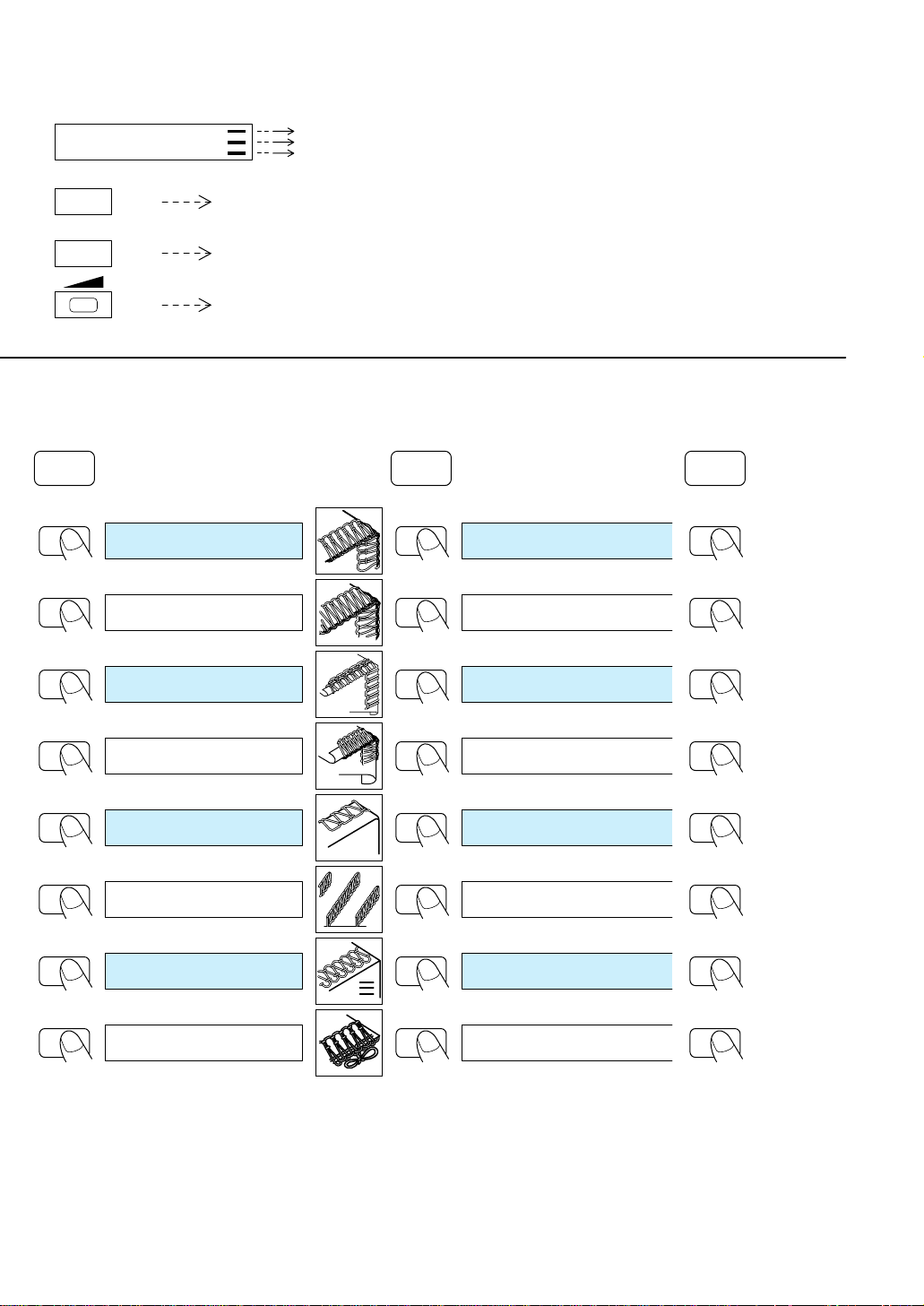
The numbers indicate the thread tension dial settings.
y
Upper right thread
Upper left thread Lowerlooper thread
3–5 3–5 3–5 3–5
The black squares indicate that it is not necessary to adjust this thread tension dial.
The thread tension dial
settings for sewing on normal
fabrics are displayed.
3–5 3–5 3–5 3–5
Upperlooper thread
INF INF
6
5
4
3
2
The thread tension dial
settings for sewing on thick
fabrics are displayed.
4–6 4–6 3–5 3–5
6
5
4
3
2
6
5
4
3
2
6
Stronger tension
5
4
3
Weaker tension
2
3
4
3–5 3–5 3–5 3–5
SELECT
INF
CONTENTS
TABLE OF
Chapter
1
Chapter
2
Chapter
3
Chapter
4
Chapter
5
Chapter
6
Chapter
7
Chapter
8
3–5 4–6 3–5
4–6 4–6 5–7
4–6 4–6 4–6
0–2
0–3
3–5 3–5 3–5 3–5
5–7 2–4
4–6 6–8 4–6
2–5 6–9
4–6 4–6 3–5
NOT RECOMMENDED
NOT RECOMMENDED
0–3
NOT RECOMMENDED
0–3
4–6 4–6 3–5 3–5
5–7 2–4
2–5 6–9
3
The thread tension dial settings for sewing
on thin fabrics are displayed.
3–5 4–6 3–5
4–6 4–6 5–7
4–6 4–6 4–6
NOT RECOMMENDED
3–5 6–8 4–6
NOT RECOMMENDED
3–5 3–5 3–5 3–5
9
10
11
12
13
14
15
16
17
Chapter
Chapter
Chapter
Chapter
Chapter
Chapter
Chapter
Chapter
Chapter
If this key is pressed one more time, the stitch
4
applications and instructions are displa
ed again.
10
18
19
Chapter
Chapter
Pantalla electrónica
(sólo para los modelos provistos con pantalla de una línea)
Pantalla de cristal líquido (LCD) Espesor del tejido
Pantalla de cristal líquido
SELECT
NOTA: El hilo de poliéster N.° 60 es el tipo de hilo estándar.
SELECT INF INF
(LCD)
Tecla de selección de
INF
Seleccione la puntada deseada.
puntada
Tecla de información
Palanca de ajuste del
contraste
Gruesa
Normal
Fina
Pueden seleccionarse ocho puntadas.
Se visualiza la información sobre la puntada
seleccionada, su operación y los ajustes
apropiados de tensión del hilo.
Sirve para ajustar el contraste de la pantalla.
Se visualizan las aplicaciones de
puntada y las instrucciones.
CONTENTS
TABLE OF
Chapter
1
Chapter
2
Chapter
3
Chapter
4
Chapter
5
Chapter
6
Chapter
7
1) 4 REMATADO
12
2) 3 REMATADO
3) PUNT.CURLING
4) FESTON.CORTO
5) PUNT.INVISIBLE
6) LORZAS
7) COSTURA PLANA
8) VIVOS
Rematado de 4 hilos al b....
Rematado de 3 hilos al b....
Realiza un acabado tipo.....
Acabado tipo festón esre....
Se usa para hacer un dob...
Puntada decorativa o lorz...
Puntada decorativa plana...
Aplicación de vivos usan.....
8
9
10
11
12
13
14
15
16
Chapter
Chapter
Chapter
Chapter
Chapter
Chapter
Chapter
Chapter
Chapter
Se visualizan los ajustes de disco de tensión del hilo
para tejidos finos cuando se presiona la tecla [INF].
12
El nombre de esta puntada se visualiza
cuando se conecta la alimentación
Se visualiza el mismo mensaje dos veces antes de que
se visualizan automáticamente los ajustes de disco de
tensión del hilo para coser con tejidos finos.
11
17
18
19
Chapter
Chapter
Chapter
Los números indican los ajustes del disco de tensión del hilo.
y
Hilo superior derecho
Hilo superior
izquierdo
3–5 3–5 3–5 3–5
Los recuadros negros indican que no es necesario ajustar este disco de tensión del hilo.
Se visualizan los ajustes de
disco de tensión del hilo para
coser con tejidos normales.
3–5 3–5 3–5 3–5
Hilo de áncora superior
Hilo de áncora superior
INF INF
Se visualizan los ajustes de
disco de tensión del hilo para
coser con tejidos gruesos.
4–6 4–6 3–5 3–5
6
5
4
3
2
6
5
4
3
2
6
5
4
3
2
6
5
4
3
2
Tensión más fuerte
Tensión más floja
3
4
3–5 3–5 3–5 3–5
SELECT
INF
CONTENTS
TABLE OF
Chapter
1
Chapter
2
Chapter
3
Chapter
4
Chapter
5
Chapter
6
Chapter
7
Chapter
8
3–5 4–6 3–5
4–6 4–6 5–7
4–6 4–6 4–6
0–2
0–3
3–5 3–5 3–5 3–5
5–7 2–4
4–6 6–8 4–6
2–5 6–9
4–6 4–6 3–5
NO RECOMENDADO
NO RECOMENDADO
0–3
NO RECOMENDADO
0–3
4–6 4–6 3–5 3–5
5–7 2–4
2–5 6–9
3
Se visualizan los ajustes de disco de tensión del
hilo para coser con tejidos finos.
3–5 4–6 3–5
4–6 4–6 5–7
4–6 4–6 4–6
NO RECOMENDADO
3–5 6–8 4–6
NO RECOMENDADO
3–5 3–5 3–5 3–5
9
10
11
12
13
14
15
16
17
Chapter
Chapter
Chapter
Chapter
Chapter
Chapter
Chapter
Chapter
Chapter
Si se presiona otra vez esta tecla, se volverán a visualizar
4
las aplicaciones de la puntada
las instrucciones.
12
18
19
Chapter
Chapter
CONTENTS
TABLE OF
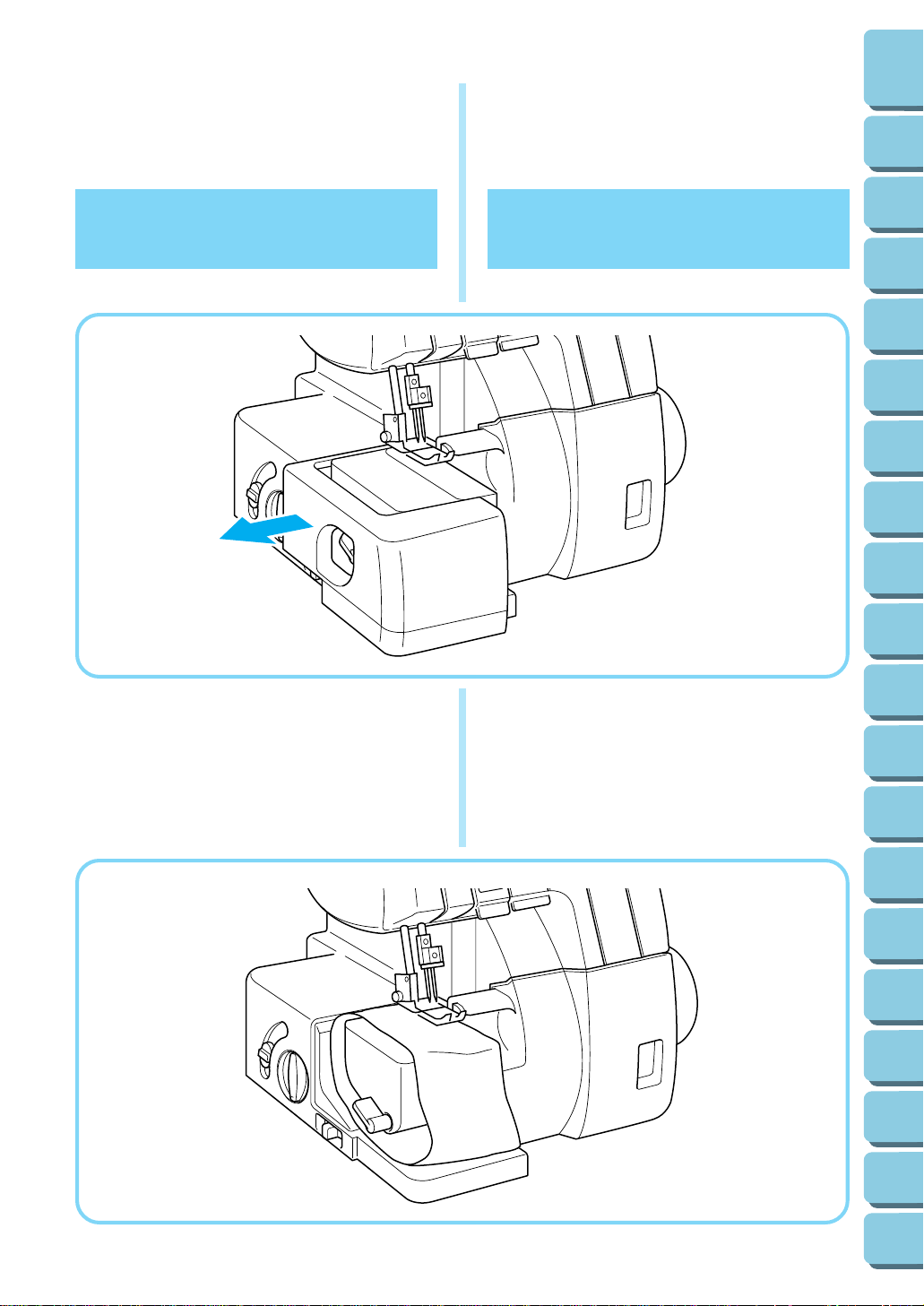
Removing the
Bed Extension for
Free-Arm Sewing
Removing the bed extension
Extraiga el suplemento
para la mesa para realizar la costura sin brazo
Extraiga el suplemento
para la mesa
1
2
3
4
5
6
7
8
9
Chapter
Chapter
Chapter
Chapter
Chapter
Chapter
Chapter
Chapter
Chapter
Free-arm sewing enables tubular pieces to be sewn
more easily. For free-arm sewing, remove the bed
extension and position the fabric as shown in the
illustration.
La costura sin brazo permite coser trozos tubulares
de tejido de forma más sencilla. Para llevar a cabo la
costura sin brazo, extraiga el suplemento para la
mesa y coloque el tejido tal y como se indica en la
ilustración.
10
11
12
13
14
15
16
17
18
Chapter
Chapter
Chapter
Chapter
Chapter
Chapter
Chapter
Chapter
Chapter
13
19
Chapter
CONTENTS
TABLE OF
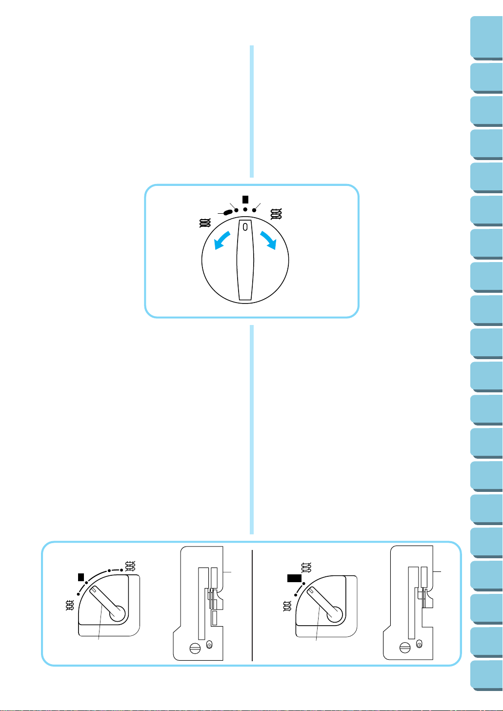
Stitch Length
To change the stitch length,
(1)Locate the stitch length adjustment dial on the left
side of the machine.
(2)Turn the stitch length adjustment dial forward to
lengthen the stitch to a maximum of 4 mm (5/32
inch).
Turn the stitch length adjustment dial backwards
to shorten the stitch length to a minimum of 2 mm
(1/8 inch).
(3) The normal stitch length setting is 2.5 mm to 3
mm.
2
R
Stitch Width
Two-needle models
To change the stitch width.
(1)Move the stitch width lever (located on the left side
of the machine toward the front) up to reduce the
stitch width or down to increase the width.
The stitch width can be set between R4.5 mm (11/
64 inch) and 7 mm (9/32 inch).
The normal stitch width setting for regular overlock
stitch is 5mm (13/64 inch).
One-needle models
• The width is factory set to 3.5mm (9/64 inch).
A Two-needle models
B One-needle models
1 Stitch width lever
2 Regular needle plate
Largo de puntada
Para cambiar el largo de las puntada:
(1)Busque el disco de ajuste del largo de las punta-
das en al lado izquierdo de la máquina.
(2)Gire el disco de ajuste del largo de las puntadas
hacia adelante para alargar la puntada a un
máximo de 4 mm.
Gire el disco de ajuste del largo de las puntadas
hacia atrás para acortar la longitud de puntada a
un mínimo de 2 mm.
* Un ajuste normal para el largo de las puntadas se
sitúa entre 2,5 y 3 mm.
3
4
Ancho de puntada
Modelos de dos agujas.
•
Para cambiar el ancho de puntada.
(1) Mueva la palanca de anchura de las puntadas
(situada a la izquierda de la máquina, hacia
adelante) hacia arriba para reducir el ancho de
puntada, o hacia abajo para aumentar el ancho
de puntada.
Puede ajustar el ancho de puntada entre R4,5
mm y 7 mm.
El ajuste normal del ancho de puntada para una
puntada overlock corriente es de 5 mm.
Modelos de una aguja.
•
El ancho de las puntadas está establecido en la
fábrica en 3,5 mm.
A
Modelos de dos agujas
B
Modelos de una aguja
1
Palanca de anchura de las puntadas
2
Place de aguja normal
1
2
3
4
5
6
7
8
9
10
11
12
13
14
15
Chapter
Chapter
Chapter
Chapter
Chapter
Chapter
Chapter
Chapter
Chapter
Chapter
Chapter
Chapter
Chapter
Chapter
Chapter
A
Chapter
7
6
5
R
1
2
B
R
3.5
2
1
16
17
18
19
Chapter
Chapter
Chapter
14
CONTENTS
TABLE OF
Instructions for the
Differential Feed
Mechanism (Models
with Differential Feed)
This serger is equipped with two sets of feed dogs
under the presser foot to move the fabric through the
machine. The differential feed controls the movement of both the front and the rear feed dogs. When
set at 1, the feed dogs are moving at the same speed
(ratio of 1). When the differential feed ratio is set at
less than 1, the front feed dogs move slower than the
rear feed dogs, stretching the fabric as it is sewn.
This is effective on lightweight fabric that may pucker.
When the differential feed ratio is set at greater than
1, the front feed dogs move faster than the back feed
dogs, gathering the fabric as it is sewn. This function
assists in removing the rippling when serging stretch
fabrics.
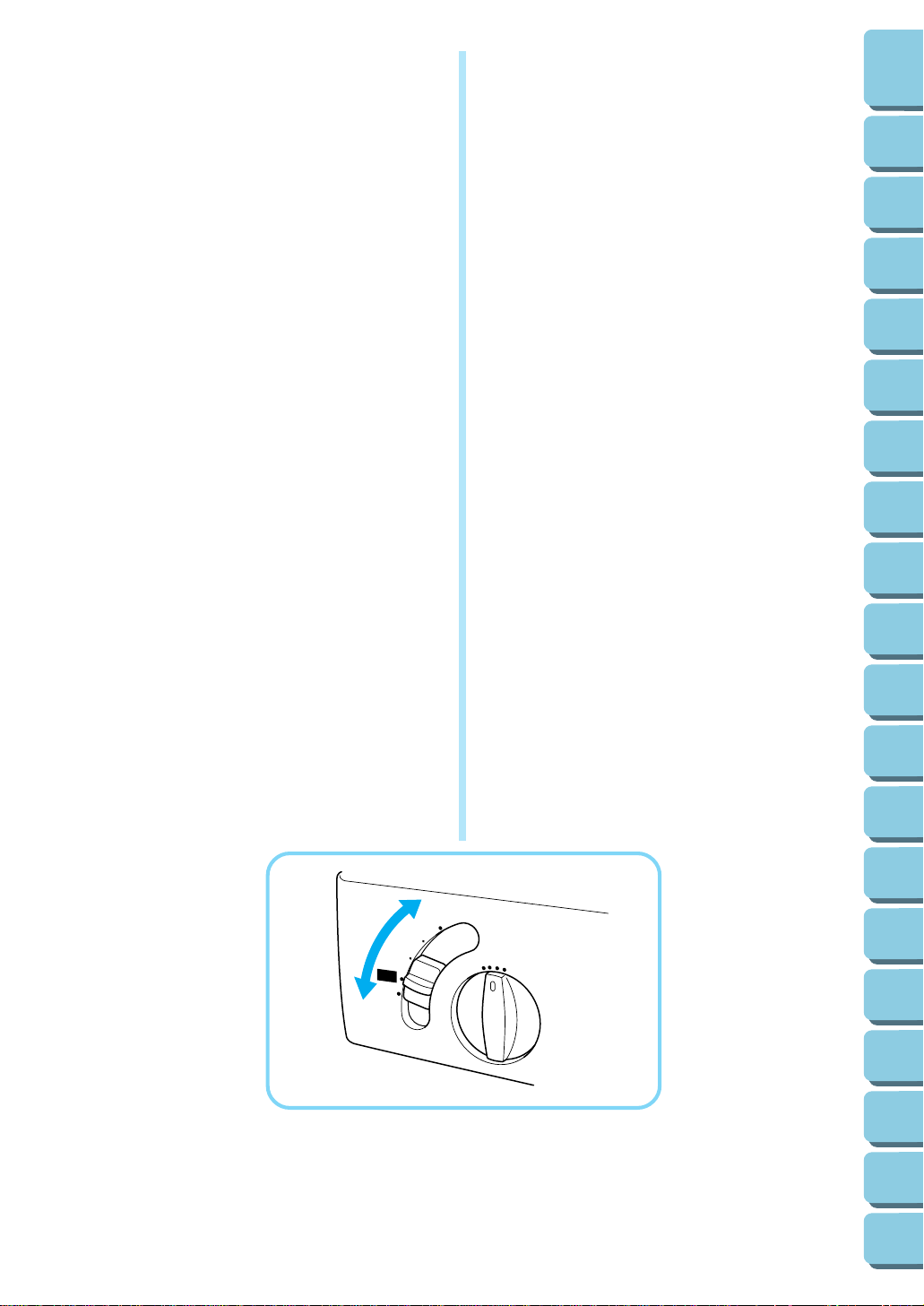
• To adjust the differential feed.
(1) Locate the differential feed adjustment lever on
the left side of the machine.
(2)The normal setting is 1.0 on the differential feed
adjustment lever.
(3)To set less than 1.0, move the lever back.
(4)To set greatev than 1.0, move the lever forward.
Instrucciones para el
mecanismo de alimenta-
ción con diferencial
(Modelos con
alimentador diferencial)
Esta máquina de coser está provista de dos series
de alimentadores debajo del prensatelas para guiar
el tejido por la máquina. El alimentador con diferencial controla los movimientos de los alimentadores
delanteros y traseros. Al ajustarlo en 1, los
alimentadores se desplazarán a una velocidad idéntica (relación de 1). Al ajustar la relación del
alimentador con diferencial en menos de 1, los
alimentadores delanteros van a moverse más despacio que los traseros, estirando el tejido a medida
que se cuese. Esta operación resulta muy eficiente
al coser materiales finos que pueden arrugarse.
Cuando el alimentador con diferencial esté ajustado
en un valor superior a 1, los alimentadores delanteros van a moverse más rápido que los alimentadores
traseros, juntando el tejido al coserlo. Esta función
permite quitar las arrugas al coser tejidos que se
estiran.
•
Para ajustar el alimentador diferencial.
(1)Busque la palanca de ajuste del alimentador
diferencial en al lado izquierdo de la máquina.
(2)El ajuste normal es de 1,0 en la palanca de ajuste
del alimentador diferencial.
(3) Para ajustar menos de 1,0, mueva la palanca
hacia atrás.
(4)Para ajustar más de 1,0, mueva la palanca hacia
adelante.
1
2
3
4
5
6
7
8
9
10
11
12
Chapter
Chapter
Chapter
Chapter
Chapter
Chapter
Chapter
Chapter
Chapter
Chapter
Chapter
Chapter
15
1.0
13
14
15
16
17
18
19
Chapter
Chapter
Chapter
Chapter
Chapter
Chapter
Chapter
 Loading...