

Page 1
!
!
!
!
!
!
!
!
!
!
!
!
"#$%&'(%)!*&+,&-!
./%0,-&'/+1!2&'3)!4/'3!5%(1%&66&7-$!.(+'%(--$%!!
!
!
!
!
110-242 3/10/09
Page 2

1
8&7-$!(9!.(+'$+')!
Section 1 - General Information
1.1 Unpacking
1.2 Contents
1.3 General Description
Section 2 - Circulator Pump Connections
and Setup
2.1 Circulator Pump
2.2 Pump Inlet and Outlet Connections
2.3 Closed Loop Circulation
2.4 Open Loop Circulation
2.5 Filling the Reservoir
2.6 Reservoir Purge
Section 3 - Programmable Controller
Information
3.1 Front and Rear Panels
3.2 Heater/Pump Assembly
3.3 Specifications
Section 4 - Operation
4.1 Circulator Location
4.2 Reservoir Liquid Level
4.3 External Temperature Probe
4.4 RS232 Interface
4.5 Power
4.6 Setting the Safety Set Point
4.7 Power On
4.8 Local Lockout
4.9 Setting the Bath Temperature Set Point
4.10 Menu Navigation
4.11 Setting Operational Parameters and
Functions
4.11.1 Setting and Starting the Timer
4.11.2 Entering/Modifying a Temperature
Program
4.11.3 Writing a Temperature Program
4.11.4 Running a Temperature Program
4.11.5 Setting Preferences
4.11.6 Setting High/Low Temperature
Limits and Alarms
4.11.7 Selecting the Pump Speed
4.11.8 Fluid type (specific heat)
4.11.9 Displaying the Bath Temperature
Trend
4.11.10 Selecting the Temperature Probe
(Internal or External)
4.11.11 Setting the Auto-Refrigeration
Temperature
4.11.12 Setting the Display Contrast and
Timeout
4.11.13 Setting the Baud Rate
4.12 Controller Messages
Section 5 - Maintenance and Calibration
5.1 Heater
5.2 Pump Motor
5.3 Cleaning
5.4 Maintaining Clear Bath Water
5.5 Condenser, Air Vents, and Reusable Filter
(Refrigerating/Heating Circulators Only)
5.6 Calibration
Section 6 - Troubleshooting
6.1 Unit Will Not Operate (no heat, cooling, or
pumping)
6.2 No Pumping
6.3 Slow or Insufficient Pumping
6.4 No Heating
6.5 Insufficient Heating
6.6 No Cooling or Insufficient Cooling
6.7 Triac Failure
6.8 External Probe Failure
6.9 Recalling the Power-Up Language
Selection Menu
Section 7 - Reservoir Fluids
Section 8 - Appendix
8.1 Using Bath Controller with Rheocalc
Software
8.2 Using Bath Controller with DV-III+ or DV-III
Ultra Rheometer in Standalone Mode
8.3 RS232 For use without Brookfield
Software (for customers using their own
software)
Section 9 - Service and Technical Support
9.1 Replacement Parts
Section 10 - After-sale Support
Section 11 - Warranty
Section 12 - EC Declaration of Conformity
Section 13 - WEEE Declaration
!
!
Page 3
2
!
This symbol marks chapters and sections of this instruction manual which are particularly relevant to safety. When
!
attached to the unit, this symbol draws attention to the relevant s ection of the instruction manual.
!
This symbol indicates that hazardous voltages may be present.!
!
:$&;!&--!/+)'%,0'/(+)!#$%'&/+/+1!'(!)&9$'<=!)$'>,#=!&+;!(#$%&'/(+?!
5%(#$%!(#$%&'/(+!/)!'3$!,)$%)@!%$)#(+)/7/-/'<?!
!
$0'/(+!!>!$+$%&-!+9(%6&'/(+!
?! +#&0/+1!
Your circulator is shipped in a special carton. Retain the carton and all packing materials until the
unit is completely assembled and working properly. Set up and run the unit immediately to confirm
proper operation. Beyond one week, your unit may be warranty repaired, but not replaced. If the
unit is damaged or does not operate properly, contact the transportation company, file a damage
claim and contact the company where your unit was purchased.
Remove any loose packing material that may have fallen into the reservoir during shipping. Before
powering up, check that nothing remains around the heater or circulator pump.
The instructions in this manual pertain to circulating baths both refrigerated and cooling coil types.
Read the section pertaining to the special instructions for your model.
?!! .(+'$+')!!
Circulator Bath TC-102P TC-202P TC-502P TC-602P TC-900P
Operators Manual, warranty
card
RS-232 Communication Cable RSS-E1
3
/16 in., ¼ in., and 3/8 in. Nylon
Barbed Tubing Adapters
6 ft. of ¼ in. ID Latex Tubing HT-Tubing
Adapter Fittings* ¼ in. NPT – M16, Male (qty 2)
Beaker Platform(s) for Bath
Reservoir
— 600 ml
— 1000ml
Deck Lid(s)
— Solid
— w/Beaker Holes
Blue Hole Plugs
— 3 1/2 inch
— 4 ¼ inch
Note: Do Not Use Above 120°C
IEC Power Cord (qty 1)
701-402
510-209
510-211
TBPS300-295
701-402 (qty 2)
701-403
510-210
TBPS300-295
(qty 2)
TBPS300-296
110-242
510-011
701-402
510-290
510-293
TBPS300-295
701-402
510-246
510-484
Note: Work area "opening" is designed to measure samples directly in the bath. If additional viscometer height is
required (spindle/guard clearance), either a 4 inch rod extension (part number BLM-4E) used with type A lab stand
or an 18 inch rod replacement (part number VS-38) used with type S lab stand are available from Brookfield or an
authorized dealer.
* Included with 50Hz Models only.
Page 4
3
?! $+$%&-!$)0%/#'/(+!!
Refrigerating/Heating and Heat Only Circulating Baths with the Programmable Controller are
designed for use as stand-alone baths or to provide precise temperature control of fluids for open or
closed loop circulation to external equipment. Refrigeration is normally required for operation at
temperatures below 40°C.
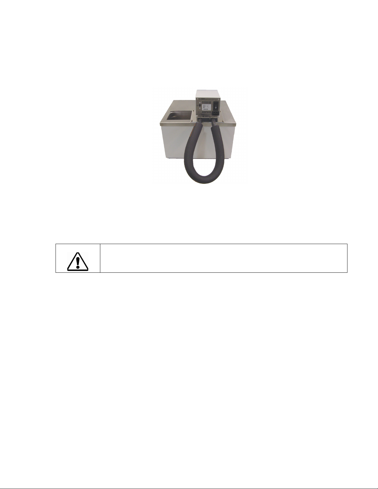
All Circulating Bath models feature a reservoir, which may be used for immersing samples while the
unit is connected to an external device. Circulating Bath models are equipped with a 6 or 10 liter
reservoir. All wetted parts are corrosion-resistant 300 series stainless steel.
Warning: These units are equipped with over-temperature protection (Safety Set). A low-liquid
level or failure to set the Safety Set and properly immerse the heater may result in heater burnout
and triac failure. While operating, do not allow the heater to contact any potentially flammable
materials, such as plastic trays or the sides of plastic tanks, as a fire hazard may result.
$0'/(+!!J!./%0,-&'(%!5,6#!.(++$0'/(+)!&+;!$',#!
?!!! ./%0,-&'(%!5,6#!
The Circulator’s variable speed duplex (pressure/suction) pump may be used for tempering of
samples in the reservoir or for circulation in open or closed loop systems.
Pump speed is selected via the Main Menu (see Section 4.11.7 – Selecting the Pump Speed).
The Low setting is adequate for most applications and provides quieter pumping. High is
recommended where temperature varies frequently and there is a need for fast recovery or when
pumping to multiple external units.
Maximum Pump Outlet Ratings
Line Frequency = 60Hz LineFrequency = 50Hz
Variable up to: 30 LPM / 5.0 PSI 22 LPM / 3.4 PSI
This data is based on the following criteria:
1. Maximum pump outlet flow rate is measured in liters per minute (LPM) with no restriction on the pump outlet.
2. Maximum pump outlet pressure is measured in pounds per square inch (PSI) at no flow.
3. Water was used as the circulation fluid. W ater has a viscosity of one centistoke. High viscosity or low-density
fluids will change these figures.
Page 5
4
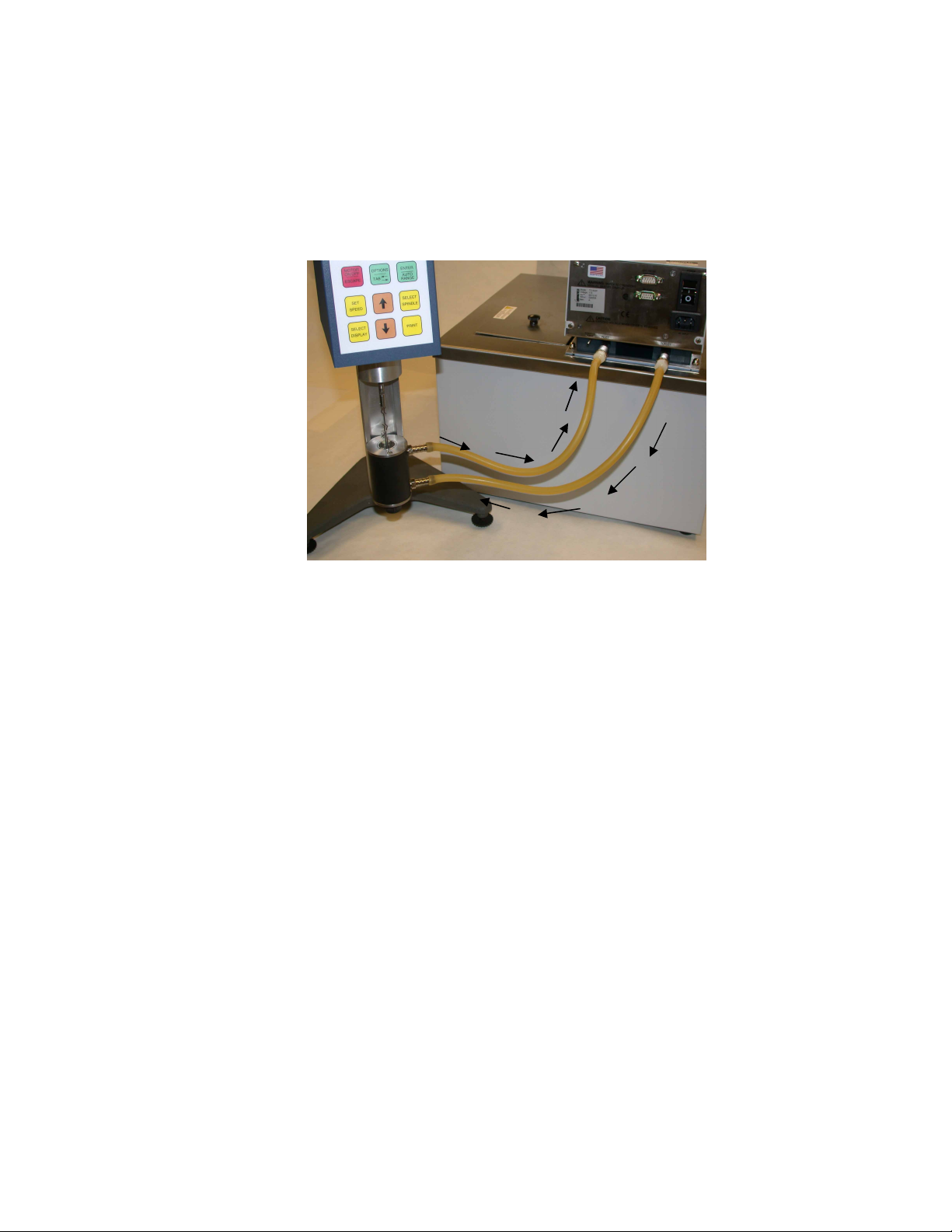
?! 5,6#!+-$'!&+;!",'-$'!.(++$0'/(+)!!
The pump inlet and outlet ports are female ¼ inch NPT connections that permit use of barbed tubing
adapters or hard plumbing fittings. ½ inch (13mm) ID tubing may also be slid over these connections
and held in place with a hose clamp. If the pump inlet and outlet are not used for external circulation,
they should be connected using the tubing provided with the unit in order to optimize fluid mixing
within the reservoir.
Picture 1: Inlet to outlet connection. When bath is not circulating with an external
device, the tubing provided with the unit should be used as shown above.
The nylon barbed tubing adapter fittings supplied with the unit are intended for temperature control
from -40° to 93°C. For controlling temperature above 93°C, brass, stainless steel, or Teflon® fittings
are recommended. ¼ inch NPT to M16 stainless steel male adapter fittings are provided with all
50Hz models.
IT IS THE USER’S RESPONSIBILITY TO ENSURE THAT THE TUBING AND FITTINGS
CONNECTED TO THE CIRCULATOR ARE COMPATIBLE WITH THE BATH FLUID AND
TEMPERATURE RANGE BEING USED.
NOTE: The use of quick-connect fittings will restrict flow rate. Therefore a high or maximum pump
speed should be used.
Page 6
5
?!! .-()$;!K((#!./%0,-&'/(+!
Connect the pump inlet and outlet to the external apparatus (See Picture 2 below). To maintain
adequate flow, avoid restrictions in the tubing. When connecting the Circulator to more than two
closed loops, the use of a manifold made of "Y" adapters to divide the fluid into multiple banks is
recommended. After setting up multiple closed loops, check for adequate flow at the return manifold
of each loop and check that the bath fluid is at an adequate level. A booster pump may be added to
closed loops without damaging the Circulator’s bath pump.
Picture 2: Flow Connections: Small Sample Adapter (shown), DIN
and UL Adapters, or Cone and Plate Viscometers
The temperature control stability of a closed loop system is better at the external apparatus than in
the Circulator reservoir (provided the control point of the apparatus represents a constant load and is
well insulated). For example, if you circulate fluid through a viscometer at 50°C, the temperature
variation observed in the Circulator reservoir may be ±0.2°C while the temperature variation in the
viscometer may be only ±0.1°C.
Although temperature stability is generally better at the external apparatus control point, depending
on the length of tubing used and the efficiency of the insulation, the actual temperature reading at
the external apparatus may be slightly different than the temperature reading at the Circulator
reservoir.
BATH
INLET
BATH
OUTLET
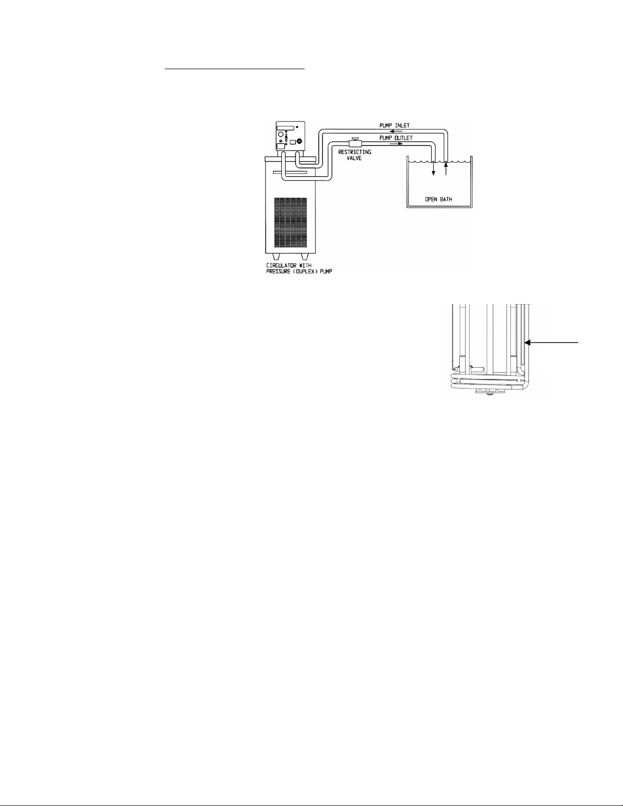
?L!! "#$+!K((#!./%0,-&'/(+!
The duplex pump permits circulation to and from an external open bath. To prevent siphoning when
the Circulating Bath is turned off, position both baths so that the two fluid levels are at the same
elevation.
Connect the pump inlet and outlet to the external bath using tubing of the same diameter and length.
The same size fittings should also be used on both the inlet (suction) and outlet (pressure). This
helps ensure a balanced flow. A restricting valve or pinch clip should be installed in the pressure
(outlet) tubing and adjusted to match the return suction (inlet) flow rate. Cut the external end of the
suction tube into a “V” shape so that the tube will not seal itself against the wall of the external tank.
Both the pressure and suction tubing should be securely fastened to the external tank to prevent
movement during use.
When using flexible tubing, the suction tubing must have a wall thickness that will not collapse under
vacuum, particularly when going around bends.
Page 7
6
Circulating Bath Height Regulation — Position the ends of the pressure and suction tubes at the
desired maximum fluid level in the external bath and fill the bath to that level. Fill the Circulating bath
to a height one inch (25mm) below the top of the reservoir. Start the pump and adjust the restricting
valve/pinch clip on the pressure tubing until the liquid height in both baths remains constant. Add
fluid to the baths as needed to compensate for the fluid in the inlet and outlet lines.
?M! N/--/+1!'3$!:$)$%O(/%!!
The maximum fill level for the Circulating bath is one inch
(25mm) below the top of the reservoir. A liquid level that fully
covers the heater coil, pump, over-temperature sensor, and at
least one inch (25mm) of the temperature sensor must be
maintained. For optimum cooling efficiency, the bath fluid level in
Refrigerating/Heating Circulators should be kept above the
cooling coils at all times.
Upon start-up, it may be necessary to add fluid to compensate
for the fluid required for external circulation. If the proper fluid
level is not maintained, the heater coil may become exposed and possibly damaged.
Minimum fill
level
?P! :$)$%O(/%!5,%1$!
When operating at low temperatures, atmospheric moisture tends to migrate into the reservoir and
condense. The 1/8 inch OD Reservoir Purge tube allows you to inject inert gas into the Circulating
Bath to prevent the build-up of condensation.
!
Page 8
7
$0'/(+!!>!5%(1%&66&7-$!.(+'%(--$%!+9(%6&'/(+!
3 4 5
11 12
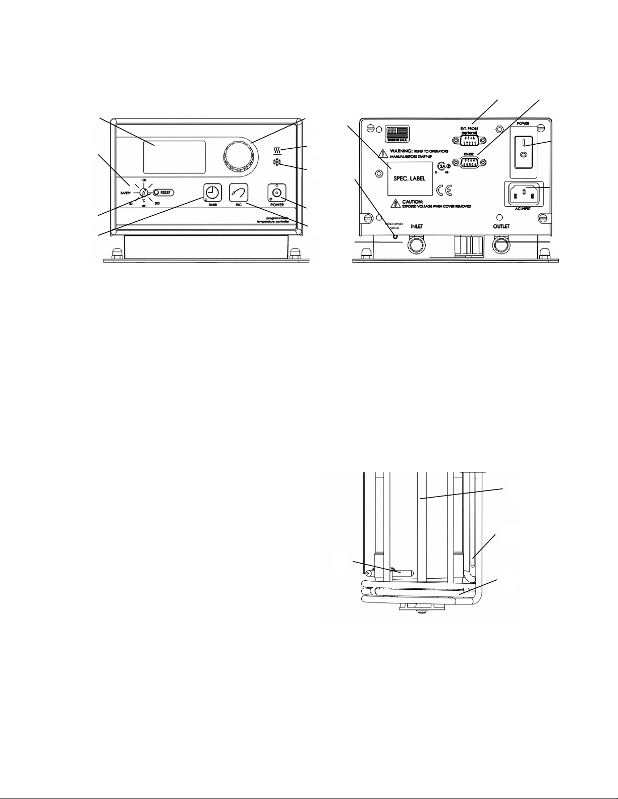
!?! N%(+'!&+;!:$&%!5&+$-)!
2
Front View Rear View
1. Select / Set Knob 10. Identification Label
2. LCD Display 11. Reservoir Purge
3. Safety Set Indicator Knob 12. Pump Inlet
4. Safety Set Reset Button 13. Pump Outlet
5. Timer Button 14. AC Input
6. Escape Button 15. External Probe Connection
7. Power On/Off Button 16. RS232 Interface
8. Heating Light 17. Circuit Breaker / AC Power Switch
9. Cooling Light1
1
Functional on Refrigerating/Heating Circulating Baths only
15
1
10
8
9
7
6
16
17
14
13
?! Q$&'$%R5,6#!S))$67-<!
1. Temperature Sensor
2. Pump Shaft and Impeller
3. Over-Temperature Sensor
4. Heater Coils
3
2
1
4
Page 9

8
?! #$0/9/0&'/(+)!!
Model TC-102P TC-202P TC-502P TC-602P TC-900P
Temperature Range
Cooling Tap Water* Tap Water* Refrigerated Refrigerated Refrigerated
Reservoir Capacity 6.0 liter 10 liter 6.0 liter 6.0 liter 13.0 liter
Temperature Stability ±0.01°C
Controller / RS232 Yes
External Temperature Probe Functional on Programmable models / optional external probe required
Readout Accuracy Graphic LCD, °C or °F, ±0.25°C
Heater 1100W – 115V, 2200W – 240V
Pressure Flow Rate 15.7 to 30 LPM (60Hz); 15 to 22 LPM (50Hz)
Suction Flow Rate 11 to 22 (60Hz); 10 to 15 LPM (50Hz)
Over-Temperature Protection
Low-Liquid Protection Yes
Pump Speeds Variable
Pump Inlet and Outlet ¼ inch FPT rear discharge. (M16, Male - 50Hz Models Only)
Dimensions in.
(l x w x h) cm
Unit Weights 22 lbs (10.0 kg) 28 lbs (12.7 kg) 63 lbs (28.6 kg) 68 lbs (30.9 kg) 145 lbs (66 kg)
-20° to 200°C -20° to 150°C -20° to 200°C -20° to 200°C -40° to 200°C
Yes, user-adjustable Safety Set Point
143/4 x 81/4 x 14
37.5 x 13.3 x 35.6
131/4 x 141/4 x 131/
33.7 x 36.2 x 33.7
153/4 x 183/4 x 17
4
40 x 47.6 x 43.2
153/4 x 81/4 x 221/
40 x 21 x 57.1
17 x 15½ x 24¾
2
43.2 x 39.4 x 62.9
Reservoir Volumes 6.0 liters 10.0 liters 6.0 liters 6.0 liters 13.0 liters
Power Requirement 11A @
115V / 1 / 60Hz
(105V - 125V)
9.8A @
240V / 1 / 50Hz
(200V - 260V)
NOTE: Performance specifications determined at ambient temperature of 20°C (68°F).
* For use at lower temperatures, use the built-in tap water cooling, or use model TC-351 Cooler for control to -20°C
11A @
115V / 1 / 60Hz
(105V - 125V)
9.8A @
240V / 1 / 50Hz
(200V - 260V)
12A @
115V / 1 / 60Hz
(105V - 125V)
9.9A @
240V / 1 / 50Hz
(200V - 260V)
12A @
115V / 1 / 60Hz
(105V - 125V)
9.9A @
240V / 1 / 50Hz
(200V - 260V)
14A @
115V / 1 / 60Hz
(105V - 125V)
9.9A @
240V / 1 / 50Hz
(200V - 260V)
Environmental Conditions:
! Indoor Use Only ! Over Voltage: Category ll
! Maximum Altitude: 2000 meters ! Operating Ambient: 5° to 30°C
! Relative Humidity: 80% for temperatures to 30°C ! Pollution Degree: 2
! Class 1: Residential, Commercial, Light Industrial ! Class 2: Heavy Industrial
Page 10
9
$0'/(+!L!J!"#$%&'/(+!
L?!! ./%0,-&'(%!K(0&'/(+!
Locate the Circulator on a level surface, free from drafts and out of direct sunlight. Do not place it
where corrosive fumes, excessive moisture, high room temperatures, or excessive dust are present.
Refrigerating/Heating Circulators must be a minimum of four inches (102mm) away from walls or
vertical surfaces so air flow around the unit is not restricted.
To help prevent voltage drops, position the Circulator as close as possible to the power distribution
panel and a properly grounded outlet. The use of an extension cord is not recommended.
Warning: These units are equipped with over-temperature protection (Safety Set). A low liquid
level or failure to set the Safety Set and properly immerse the heater may result in heater burnout
and triac failure. While operating, do not allow the heater to contact any potentially flammable
materials, such as plastic racks or the sides of plastic tanks, as a fire hazard may result.
L?! :$)$%O(/%!K/T,/;!K$O$-!
Fill the reservoir with the appropriate bath fluid. The liquid level should be sufficient to cover the
heating coils, pump, over-temperature sensor, and at least one inch (25mm) of the temperature
sensor.
After filling the reservoir with fluid, you must set the Safety Set and the Limit High value as well as
your desired control set point temperature.
L?!! UV'$%+&-!8$6#$%&',%$!5%(7$!
The Programmable Controller is designed to accommodate an optional remote temperature probe.
The probe (order p/n DVP-94Y) attaches with an adapter (order p/n TC-54Y), to the 9-pin male
D-connector on the rear panel of the Controller.
The Controller will automatically sense the presence of the external probe when main power (rear
panel circuit breaker/power switch) is turned On. To control temperature using the external probe,
“External” must be selected via the Controller’s software. You must also set a Maximum Setpoint
Differential value. See Section 4.11 – Setting Operational Parameters and Functions - Selecting the
Temperature Probe.
To attain better temperature uniformity when using the external temperature probe in a jacketed or
air-filled vessel, stirring the external fluid with pumps or mixing air with fans is recommended. Expect
only ±1.0°C stability with air or any medium that does not conduct heat well. Insulate and cover the
entire set-up to remove temperature gradients; the Controller cannot compensate for external
chamber or component temperature gradients.
L?L! :!+'$%9&0$!
Programmable Controllers incorporate an RS232 interface to provide remote data-logging and
control capability. The 9-pin female RS232 connector is located on the rear panel of the Controller.
The RS232 interface should be connected to a serial communication port on a remote PC using an
appropriate cable (RSS-E1) supplied with the bath. Information on the RS232 command and
communication protocol can be found in Section 8.2 – RS232.
Page 11
10
L?M! ! 5(4$%!!
An IEC power cord is provided with the Circulator. This power cord should be plugged into the IEC
receptacle on the rear of the Controller and then plugged into a properly grounded outlet. Make sure
that the power outlet is the same voltage and frequency indicated on the identification label on the
back of the Controller.
The use of an extension cord is not recommended. However, if one is necessary, it must be properly
grounded and capable of handling the total wattage of the unit. The extension cord must not cause
more than a 10% drop in voltage to the Circulator.
Once the unit has been connected to an appropriate electrical outlet, place the Circuit
Breaker/Power Switch on the rear of the Controller in the ON position. The unit will run through a
self-test.
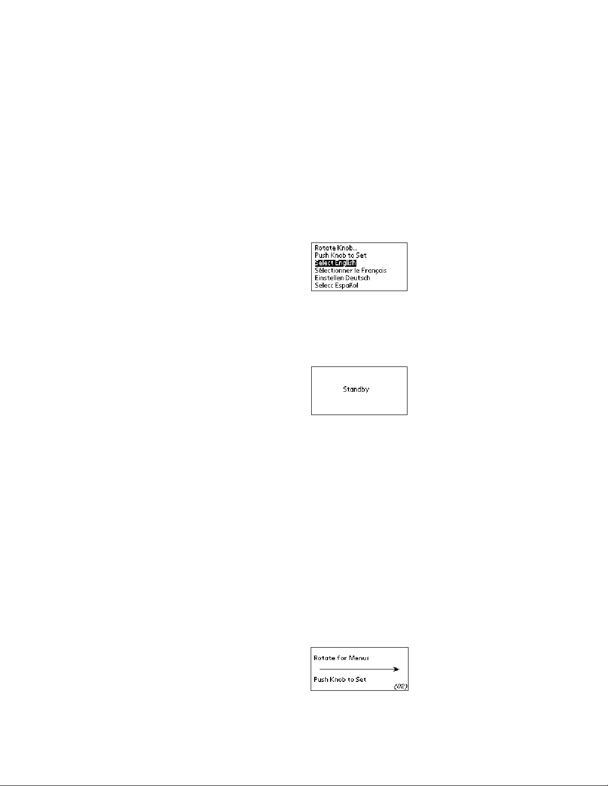
The first time power is applied to the Controller, the following display will appear. This display allows
you to select the language that will be used for all subsequent displays. The instructions for selecting
a language will be briefly displayed in each available language.
NOTE: The language selection display only appears the first time the Controller is powered up. See
Section 6 – Troubleshooting for information on recalling this display.
When the language selection display appears, rotate the Select/Set Knob until the desired language
is highlighted and then press the Select/Set Knob. The Controller will continue with the start-up
sequence and then display “Standby” on the LCD.
DO NOT place the Power Switch on the front of the Controller ON until the Safety Set has been
adjusted to the desired temperature (see Section 4.6 below).
L?P! $''/+1!'3$!&9$'<!$'!5(/+'!
The Safety Set feature automatically disconnects Controller power to the heater and pump in the
event that the reservoir liquid level drops too low or the sensed temperature exceeds the Safety Set
temperature. The Safety Set is user-adjustable between approximately 40° and 210°C. It should be
set at least 5°C higher than the desired bath temperature.
Use a flat blade screwdriver to rotate the Safety Set Indicator Knob to the desired temperature.
Do not force the knob beyond the stops at either end of the temperature value range.
If the Safety Set temperature is exceeded during normal operation, a fault message will flash on
the display and power to the heater and pump will be disrupted. To reset the fault, correct the
problem (low liquid level, incorrect Safety Set temperature, etc.), press the Safety Set Reset Button,
and then the ESC Button. Normal operation will resume.
L?W!! 5(4$%!"+!
Once the Safety Set temperature has been set, turn power to the Controller ON by pressing the
Power Switch on the front of the Controller. The following message will appear briefly on the display:
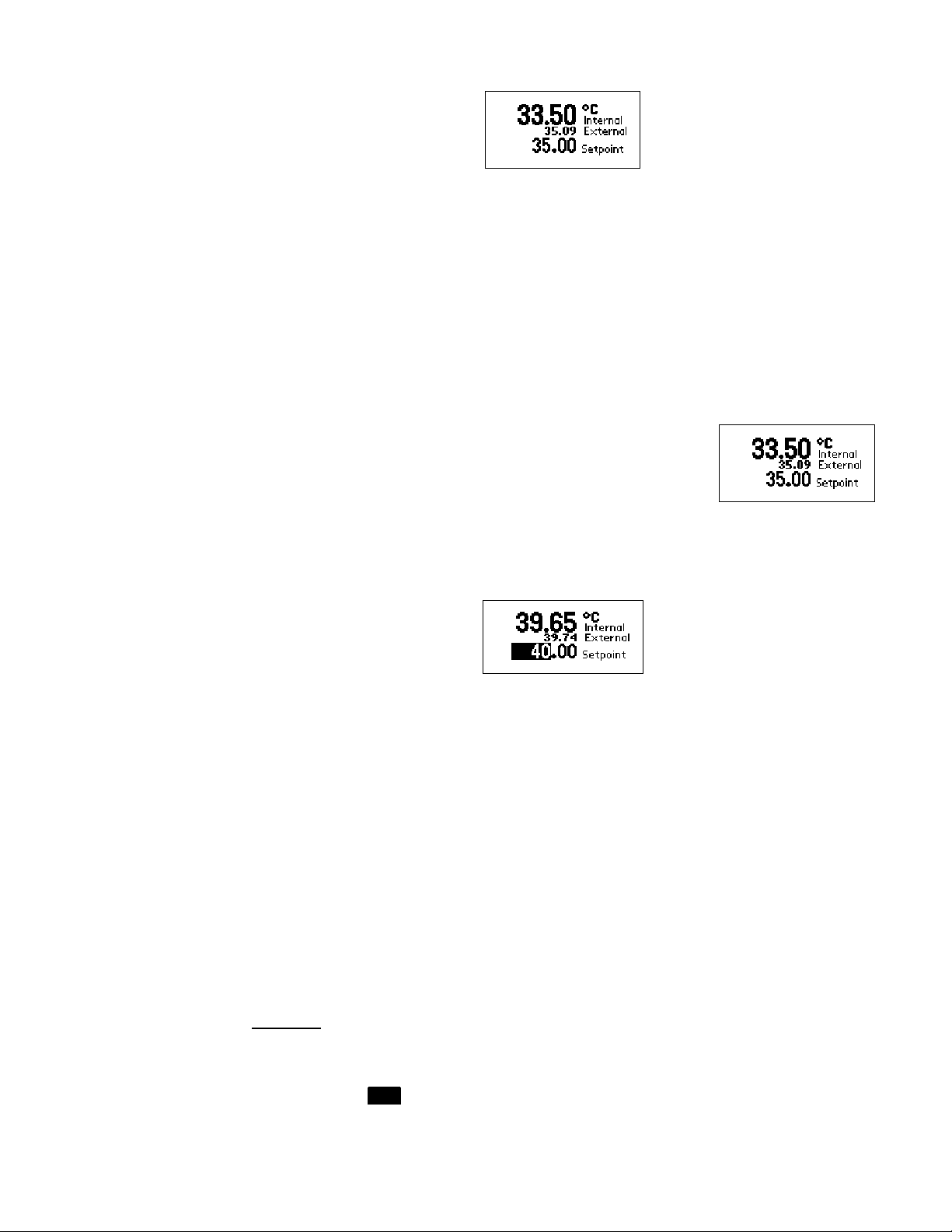
The pump will begin operating; the display will show the current bath temperature and the set point
temperature (Setpoint). If an external probe is connected, both the internal and external bath
temperatures will be displayed. The temperature probe selected to control bath temperature (internal
or external) will be displayed in larger numerals.
Page 12
11
NOTE: If the external temperature probe is selected to control bath temperature, but the temperature
!"#$%!"#&
'
difference between the set point temperature and the internal bath temperature exceeds the
Maximum Setpoint Differential setting, the heating/cooling rate will be controlled using the internal
bath temperature until the set point/internal bath temperature difference is within the Maximum
Setpoint Differential value. The word Internal will be highlighted on the display to indicate that the
internal sensor is controlling bath temperature. See Selecting the Temperature Probe in Section
4.11 – Setting Operational Parameters and Functions for more information.
L?X!! K(0&-!K(0(,'!
This enables the user to lock all controls on the controller. While the feature is activated, the unit will
remain running at the current settings.
To activate the local lockout feature, press and hold the Select/Set Knob for 10 seconds. Once
locked, “LocalLock” will appear in the upper left corner of the display. The controller menus may still
be viewed when Local Lockout is active, but no changes may be made.
Press and hold the Select/Set Knob again for 10 seconds to unlock the
controls. Once unlocked, “LocalLock” will disappear and the menu
settings can once again be modified.
L?Y! $''/+1!'3$!2&'3!8$6#$%&',%$!$'!5(/+'!
Press and release the Select/Set Knob. The “whole” numbers in the set point temperature will be
highlighted. Rotate the Select/Set Knob clockwise to increase the displayed value; rotate the knob
counter-clockwise to decrease the displayed value.
Press the Select/Set Knob to accept the new value. The decimal value in the set point temperature
digits will be highlighted. Rotate the Select/Set Knob clockwise to increase the displayed value;
rotate the knob counter-clockwise to decrease the displayed value. Press the Select /Set Knob to
accept the new value.
NOTE: Increasing/decreasing the decimal value past “0” will cause a corresponding change in the
“whole” number value. For example, if the current set point value is 24.8 and the desired value is
25.2, it is not necessary to change the 24 to a 25; increasing the decimal value from .8 to .2 will
automatically increase the 24 to 25.
The Controller will not allow you to enter a set point value above the Limit High setting or below the
Limit Low setting. Should you attempt to do so, the set point value will stop increasing/decreasing
when the Limit value is reached and a Warning message will appear on the display. You must either
change the set point or change the Limit value. See Section 4.11 – Setting Operational Parameters
and Functions – Setting High/Low Temperature Limits and Alarms.
NOTE: Programmable Controllers can also be operated using a programmed Time/Temperature
profile. See Entering/Modifying a Temperature Program and Running a Temperature Program in
Section 4.11 – Setting Operational Parameters and Functions for more information.
L?Z! *$+,
12
Sub-Menu Selections — To select an item in a sub-menu, press the Select/Set Knob. The first
available item (or the last item in that sub-menu which was selected) will be highlighted. Rotate the
Select/Set Knob clockwise to advance to the next sub-menu item; rotate the knob counter-clockwise to
go back to the previous item. Press the Select/Set Knob to select the highlighted item; the highlighting
will change from THIS to THIS, indicating that the displayed value or choice may be changed.
Entering and/or Changing Sub-Menu Values — Once the desired sub-menu item has been selected
(as described above), the displayed value is changed by rotating the Select/Set Knob. The change is
accepted by pressing the Select/Set Knob. On sub-menu items requiring multiple entries, such as
hours/minutes/seconds, an underline will appear under the first value in that sequence which can be
changed. (Example: 01:23:00 ) To accept the displayed value and/or advance to the next value in
the sequence, press the Select/Set Knob. To return to the previous cursor position, such as from
minutes back to hours, press the ESC Button. Once a value has been entered and accepted, the
highlighting box around the value will disappear. If you do not wish to accept the displayed value,
press the ESC Button or allow the display to timeout before pressing the Select/Set Knob.
Menu Structure
Main Menu Item
Timer
Program
Run Program
Preferences
Limits / Alarms
Pump Pump speed Low to High
Temperature
Trend
Probe
Auto
Refrigeration 1.
Instrument
1. This Main Menu item is present on Refrigerating/Heating Circulators only.
NOTE: There are additional displays after “Instrument “ in the Main Menu. However, there are no
user-settable functions on these displays.
Associated
Sub-Menu Items
Set
Beep
Program #
Program Steps
Program Loops
Step #
Step Setpoint
Minutes/Seconds
View Profile
Program #
Program Status
Readout
Units
Sound
Language
Program1.
Limit High
Alarm High
Alarm Low
Limit Low
No sub-menu; displays
temperature profile
Internal / External
Maximum Setpoint
Differential
Refrigeration On
Setpoint
Contrast
Timeout
Baud Rate
Choices / Ranges / Comments
00:00:01 to 99:59:59
On or Off
1 to 10
1 to 50
1 to 99
1 to 50
–50° to 200° (-50° to 392°F)
1 second to 999 minutes, 59 seconds
Displays temperature profile of program.
1 to 10
Start, Starting, Running, Paused, or Completed
#, #.#, #.##, or #.### (0, 1, 2, or 3 decimal places)
°C or °F
1 to 100
English / French / German / Spanish
Time / Temperature
-50° to 200°C (-58° to 392°F)
-50° to 200°C (-58° to 392°F)
-50° to 200°C (-58° to 392°F)
-50° to 200°C (-58° to 392°F)
2 minutes to 48 hours
Probe currently selected is shown
Only displayed when External is selected
1° to 10°C range
20° to 85°C
01 to 20
5 to 60 seconds
110 / 300 / 600 / 1200 / 2400 /4800 / 9600 /
14400 / 19200 / 38400 / 57600
Page 14

13
L?! ! $''/+1!"#$%&'/(+&-!5&%&6$'$%)!&+;!N,+0'/(+)!
All operational parameters and functions are programmed and controlled via the Controller’s
software settings. Most are user-adjustable and easily accessed via the Main Menu. The Main Menu
is accessed by rotating the Select/Set Knob. A particular Main Menu item is selected by pressing the
Select/Set Knob when that item is highlighted
4.11.1 Setting and Starting the Timer
The Timer sub-menu allows you to program the Controller’s timer to alert you once a specific period
of time has elapsed. It should be used as you would an external timer.
IMPORTANT: The Timer is independent of temperature control. It does not start or stop
heating/cooling. The Controller continues maintaining temperature at the set point even though the
designated time period has elapsed.
To set the timer, access Timer on the Main Menu, select Set, and then enter the desired period of
time. The timer’s audible signal can be turned On and Off via the selection named Beep on the
Timer sub-menu.
To start the timer, press the Timer button on the Controller’s front panel. A timer icon and Beep icon
(indicating either On – • or Off – the icon with an X through it), along with a countdown timer, will
appear on the bottom of the LCD. The Timer LED will light continuously.
Once the designated time period has elapsed, the audible signal (if enabled) will sound and the
countdown timer will display the amount of time which has elapsed since the designated time period
ended. The timer LED will flash.
To silence the audible signal and/or clear the timer display from the LCD, press the Timer Button.
The timer may also be paused at any time during the countdown period by pressing the Timer
Button. When this occurs, the Timer LED will flash and the word “Paused” will appear on the display
adjacent to the countdown timer.
Page 15

14
4.11.2 Entering/Modifying a Temperature Program
See Writing a Temperature Program (4.11.3) for information on creating a time/temperature profile.
This menu selection allows you to program and store up to ten individual time/temperature profiles.
Each program can have up to 50 steps and 99 program loops. Once a program has been entered,
any portion of it may be modified.
Program # — This is the identification number assigned to the program. It is used to select/run the
program (see Running a Temperature Program below). You may enter a number from 1 to 10. If you
enter a number that has been assigned previously, any changes made overwrite the prior program.
Program Steps — This is the number of steps in the program. A program can have from 1 to 50
different steps.
NOTE: If you are modifying a program and change the number of steps (e.g., reduce the number of
steps from 25 to 10), steps 11 through 25 will no longer appear. However, if you later increase the
number of steps in that program (e.g., from 10 to 15), the original programming for steps 11 through
15 will reappear.
Program Loops — This is the number of times the program will run before stopping. A program may
be repeated up to 99 times.
Step #, Set, MMM/SS — This is the temperature set point and time for the selected step in the program.
To enter the set point and time for the step, rotate the Select/Set Knob until a Step number is
highlighted like THIS. Press the Select/Set Knob again; the highlighting will now look like THIS.
Rotate the Select/Set Knob to scroll to the desired Step number and press the Select/Set Knob. The
boxed highlighting will move to the temperature set point field associated with that step.
Rotate the Select/Set Knob until the desired temperature set point is displayed. You may advance
the cursor (underline) to the next number in the set point field by pressing the Select/Set Knob.
Press the ESC Button to return to the previous cursor position.
Page 16

15
Once the temperature set point has been entered, press the Select/Set Knob to advance to the time
(minutes/seconds) field. Time information is entered the same way as the temperature set point
information.
When you press the Select/Set Knob to accept the time displayed time information, the highlighted box
will automatically advance to the set point temperature field associated with the next step of the program.
IMPORTANT: The time field establishes the amount of time the Controller should take to reach the
temperature set point for the next step (i.e., the ramp rate).
View Profile — This allows you to view the programmed time/temperature profile step-by-step.
Rotate the Select/Set Knob to move through the various steps in the program. When the cursor (a
vertical line) reaches the beginning of a step, a message box will appear displaying the step number,
set point, and time.
To return to the main operational display, press the ESC Button or allow the display to timeout.
4.11.3 Writing a Temperature Program
Programmable Controllers permit the user to create up to 10 different time/temperature programs,
each of which can have as many as 50 steps and be repeated up to 99 times. The following
information is intended to provide you with some guidelines for creating useful programs.
1. Circulating baths are designed primarily to hold temperatures constant rather than change
temperatures rapidly. Do not underestimate the amount of time the circulator needs to heat or
cool a fluid to a given temperature. Larger baths or circulators being used in closed or open
loops will need more time to reach a programmed set point.
2. Programs may be run using either a Time- or Temperature-based priority. If achieving
successive temperature set points is critical, Temperature should be selected as the priority. If
completing a program in a fixed amount of time is essential, Time should be selected as the
priority. See Section 4.11.5 – Preferences for more information.
3. If a program must run within a set period of time (Time priority), have the bath temperature at or
very close to the initial set point before starting the program. The program will not start running
until the set point temperature programmed for the first step is achieved.
4. To incorporate a “soak” period in the program, enter the same set point for two adjacent steps in
the program. The time duration programmed for the first step should equal the desired “soak”
period; the time duration for the second step should be short (e.g., 1 second). The temperature
set point for the last step in a program also functions as an indefinite “soak”. The Controller
maintains temperature at the last programmed set point until a new set point is entered.
5. The step time in a program establishes the ramp rate that will be used to reach the programmed
set point for the next step. If you want to increase/decrease temperature slowly, set a lengthy
step time. If you want to increase/decrease as fast as possible, set a short step time. Keep the
heating/cooling capabilities of your instrument in mind, however. If you are running a program
using Time-based priority, fluid temperature may not reach a desired set point temperature if the
time allotted is too short.
Page 17

16
Programming Examples
Example A
Initial Bath Temperature = 25°C
Program Priority = Temperature
Desired Profile: Cool bath temperature to 20°C and hold it there of 25 minutes.
Increase bath temperature to 30°C and hold it there for 15 minutes.
Increase bath temperature to 50°C over a 45 minute period.
Decrease bath temperature to 5°C and hold.
This example requires a 6-step program:
55
50
Step 4
Step 5
45
40
35
Step 2
30
25
20
Degrees C
15
10
Step 1
Step 3
Step 6
5
0
0 5 15 30 45 60 75 90 105 120 135 150 165
Minutes
Program
Step
1 20°C 5 minutes
2 20°C 1 second
3 30°C 15 minutes Fluid temperature is maintained at 30°C for 15 minutes.
4 30°C 45 minutes
5 50°C 1 second
6 5°C 1 second
Step Set
Point
Step
Duration
Controller Operation
Controller cools fluid to 20°C as fast as possible. Until
20°C temperature set point is achieved, “Starting”
appears on the display. When fluid temperature reaches
20°C, “Running” appears on the display.
Fluid temperature maintained at 20°C for 25 minutes.
Controller heats fluid as fast as possible until the 30°C set
point programmed for Step 3 is reached.
Controller slowly heats fluid until 50°C set point
programmed for Step 5 is reached. Ramp rate is based
on the 45 minute step duration.
Controller then cools fluid as fast as possible until 5°C set
point programmed for Step 6 is reached.
“Complete” appears on display. 5°C fluid temperature is
maintained until set point is changed.
Page 18

17
Example B
Initial Bath Temperature = 25°C
Program Priority = Temperature
Desired Profile: Cool bath temperature to 20°C and hold it there for 10 minutes.
Decrease bath temperature to 10°C over 15 minutes.
Hold bath temperature at 10°C for 15 minutes.
Increase bath temperature to 50°C over a 1-hour period.
This example requires a 5-step program:
55
50
45
40
35
Step 1
Step 3
Step 5
30
25
20
Degrees C
15
10
5
Step 2
Step 4
0
0 5 15 30 45 60 75 90 105 120 135 150 165
Minutes
Program
Step
1 20°C 5 minutes
2 20°C 15 minutes
3 10°C 15 minutes Fluid temperature is maintained at 10°C for 15 minutes.
4 10°C 1 hour
5 50°C 1 second
Step Set
Point
Step
Duration
Controller Operation
Controller cools fluid to 20°C as fast as possible. Until
20°C temperature set point is achieved, “Starting”
appears on the display. When fluid temperature reaches
20°C, “Running” appears on the display.
Fluid temperature is maintained at 20°C for 10 minutes.
Controller cools fluid to 10°C set point programmed for
Step 3. Ramp rate is based on the 15 minute step
duration.
Controller slowly heats fluid until 50°C set point
programmed for Step 5 is reached. Ramp rate is based
on the 1 hour step duration.
“Complete” appears on the display. 50°C fluid
temperature is maintained until set point is changed.
Page 19

18
Example C
Minutes
Step 1
Step 2
Initial Bath Temperature = 25°C
Program Priority = Temperature
Desired Profile: Cool bath temperature to 20°C as fast as possible.
Increase bath temperature to 55°C as fast as possible.
Repeat 7 times.
This example requires a 2-step program with the number of loops set to 8:
60
55
50
45
40
35
30
25
Degrees C
20
15
10
5
0
0 5 15 30 45 60 75 90 105 120 135 150 165
Program
Step
1 20°C 1 second
2 55°C 1 second
Step Set
Point
Step
Duration
Controller Operation
Controller cools fluid to 20°C as fast as possible. Until
20°C temperature set point is achieved, “Starting”
appears on the display.
When fluid temperature reaches 20°C, “Running” appears
on the display.
Controller applies heat until 55°C set point for Step 2 is
reached.
Controller loops back to Step 1, applying cooling until
20°C set point is reached.
Steps 1 and 2 repeat seven more times. When the last
loop has been completed, “Complete” appears on the
display. Fluid temperature is maintained at 55°C until the
set point is changed.
Page 20

19
4.11.4 Running a Temperature Program
The Programmable Controller can store up to 10 user-defined time/temperature programs, which
can later be run with just a few simple commands. See - Entering/Modifying a Temperature Program
above for more information.
Programs may be run using either a Time- or Temperature-based priority. This priority is selected
under Program in the Preferences menu (see Setting Preferences below).
When Time is used, the program begins running when the bath temperature reaches the
programmed set point for step one. It continues running until the total programmed length of time for
all steps has elapsed, regardless of whether the set point temperatures for steps two and above
have been achieved.
When Temperature is selected as the priority, the program begins running when the bath
temperature reaches the programmed set point for step one. Each subsequent step is run until the
programmed set point for that step is reached, regardless of how much time has elapsed.
Selecting a Program
Program menu appears and then press the Select/Set Knob.
If the Program # field is highlighted as shown above, press the Select/Set Knob and then rotate the
Select/Set Knob until the number of the program you wish to run is displayed.
Press the Select/Set Knob a second time to accept the displayed program number. If the word Start
is highlighted, rotate the Select/Set Knob one click counter-clockwise to highlight the program
number.
Running a Program — Once you have selected and accepted the program number, rotate the
Select/Set Knob until Start is highlighted. Press the Select/Set Knob; the program will automatically
begin running. The word “Starting” will appear at the lower left of the Run Program menu and will
remain there until the bath temperature reaches the set point programmed for step one. It will then
be replaced by the word “Running.”
While a program is running, the Run Program and main operational displays will alternate on the
LCD. The Run Program display shows the current step number, the target set point for the next step,
time at the current step, loop number, program status, and total elapsed time. The main operational
display shows bath temperature, set point, and program status.
— To select a temperature program, rotate the Select/Set Knob until the Run
Pausing or Stopping a Program — A program that is running may be paused or stopped at any time.
To do so, press the Select/Set Knob until Starting or Running is highlighted and then press the
Select/Set Knob again. Rotate the Select/Set Knob until the desired function (Pause / Stop) is
highlighted and then press the Select/Set Knob. If you do not wish to pause or stop the program,
select and enter Escape.
If the program has been paused, “Paused” will appear on the lower left of the display. If the program
has been stopped, “Start” will appear on the lower left of the display.
To resume running a program that has been paused, press the Select/Set Knob, select Resume,
and then press the Select/Set Knob a second time. The program will resume operation from the
point of disruption. Select Stop if you wish to stop the program or Escape if you want to keep the
program paused.
Page 21

20
If a program is stopped or paused, the Controller will control temperature using the set point value
that was active when the program was interrupted.
NOTE: If you select the Temperature Trend display, while running a program, that display will
remain on screen until the ESC Button is pressed.
End of Program
the Run Program display. The Controller will keep the bath liquid at the last temperature set point
until a new program is started or Run Program has been exited and a new set point entered.
Exiting Run Program — Once a program has been completed, “Completed” will appear at the lower
left of the Run Program sub-menu. Highlight “Completed” and then press the Select/Set Knob.
“Start” will appear. You may now return to manual set point control, run another program, or turn
Controller power Off.
Loss of Power
will resume running the program when Controller power is restored. If main power (rear panel circuit
breaker/power switch) is turned Off or electrical power is lost while a program is running, paused, or
completed (but not exited), the appropriate Fault message will be displayed upon restoration of
power (see Section 4.11 – Display Messages). Press the ESC Button to clear the Fault message;
the Controller will resume operation at the set point at which power was lost. If the program was
running or paused, it will not resume. If it was completed, it must be exited before a new program
can be run.
4.11.5 Setting Preferences
— Once the selected program has run, “Completed” will appear in the lower left of
— If the Controller is placed in Standby (front panel power turned Off), the Controller
The Preferences sub-menu allows you program global preferences regarding instrument operation.
Readout — This is the number of decimal places to which temperatures will be displayed (0, 1, 2, or 3).
Units — This is the unit in which temperatures will be displayed (°C or °F)
Sound — This is the volume level for the unit’s audible signal. When it is selected, the volume of the
audible signal changes as the Select/Set Knob is rotated. You must press the Select/Set Knob to
accept the displayed volume value; if you press the ESC Button or allow the display to timeout
without pressing the Select/Set Knob, the sound level will remain where it was previously set.
Language — This is the language used for displays. When this is selected, a sub-menu appears
with the available languages.
Program — It is used to select whether programs are run using Time or Temperature as the priority.
When Time is selected, the program begins running when the bath temperature reaches the
programmed set point for step one and continues until the total programmed period of time has
elapsed. The set point target for any given step (except step one) may or may not be reached before
the program advances to the next step.
When Temperature is selected as the priority, the program begins running when the bath
temperature reaches the programmed set point for step one. Each subsequent step runs until the
programmed set point for that step is reached, regardless of how much time has elapsed.
Page 22

21
4.11.6 Setting High/Low Temperature Limits and Alarms
The Limits/Alarms sub-menu allows you to establish temperatures at which either power to the
temperature control components (heater/condenser) will be disconnected or which Controller’s
audible alarm will sound (Alarms).
Limit High Temperature — This feature provides additional safety and protection by allowing a
selectable upper temperature limit set point. To avoid an unwanted shutdown during regular
operation, the high limit value should be set at least 5°C higher than the selected control
temperature. It should never be set higher than the Safety Set Set Point temperature (see Section
4.6)
If you attempt to enter a set point value that exceeds the Limit High value, the audible alarm will
sound and a Warning message will flash on the display when the Limit High value is reached. You
will also be prevented from increasing the set point value any further.
To clear a Limit High warning, enter a higher value for the Limit High or reduce the control
temperature set point.
If the Limit High value is exceeded during operation (due to a Controller fault, excessive heat load,
etc.), a Fault message will appear on the display and power to the heater and condenser will be
disconnected. The pump will continue to run.
Alarm High Temperature — This feature is useful if you are using the bath to cool an external
device. It alerts you when bath temperature exceeds your programmed alarm high temperature
setting (due to insufficient cooling, blocked lines, etc.).
When the Alarm High value is exceeded, a Warning message flashes on this display and the audible
alarm sounds. Heater, condenser, and pump operation continue.
To clear an Alarm High warning, correct the problem or increase the Alarm High temperature value.
Alarm Low Temperature — This feature is useful if you are using the bath to warm an external
device or need to maintain the bath at a minimum temperature. It alerts you when bath temperature
falls below your programmed alarm low temperature setting.
When bath temperature falls below the Alarm Low value a warning message flashes on the display,
and the audible alarm sounds. Heater, condenser, and pump operation continue.
Page 23

22
To clear an Alarm Low warning, correct the problem or decrease the Alarm Low temperature value.
Limit High Set Point
. Bath
Limit Low Set Po
int
. Bath set
High Temperature Alarm Set Point
.
Low Temperature Alarm Set Point
.
Low Temperature Alarm
Limit Low Temperature — This feature provides additional safety and protection by allowing a
selectable lower temperature limit set point.
If you attempt to enter a set point value that exceeds the Limit Low value, the audible alarm will
sound and a Warning message will flash on the display when the Limit Low value is reached. You
will also be prevented from decreasing the set point value any further.
To clear a Limit Low warning, enter a lower value for the Limit High or increase the control
temperature set point.
If the Limit Low value is exceeded during operation (due to a Controller fault, excessive cooling load,
etc.), a Fault message will appear on the display and power to the heater and condenser will be
disconnected. The pump will continue to run.
Limits/Alarms Example
Initial Bath Temperature = 20°C
Bath Temperature Set Point = 37°C
Limit High Temperature = 60°C
Alarm High Temperature = 40°C
Alarm Low Temperature = 35°C
Limit Low Temperature = 11°C
set point temperature cannot
70
be raised above this value.
60
50
Alarm activates if bath temperature
rises to this value.
40
30
Degrees C
20
disabled until bath temperature
rises above Low Temperature
Alarm set point value.
10
0
10 20 30 40 50 60 70 80 90
point temperature cannot be
lowered below this value.
4.11.7 Selecting the Pump Speed
Minutes
Alarm activates if bath temperature
falls to this value.
If bath temperature moves
above or below Limit
values, alarm activates and
power to the heater and
condenser is disconnected.
Pump speed is selected from the Pump menu. This display shows the current pump speed setting.
The number to the right of the bar is for reference only and is useful in providing similar pumping
characteristics when using multiple baths. See Section 2.1 for approximate pump max
pressures/flow rates.
Page 24

23
4.11.8 Fluid Type (Specific Heat)
This menu selection allows you to optimize circulator performance to the specific heat (in
calories/gram°C) of the fluid being used.
To enter a new specific heat value, press the Select/Set Knob. The current specific heat value will
be highlighted. Press the Select/Set Knob two more times and then rotate the knob until the desired
value is displayed. Press the Select/Set Knob to accept the new value.
NOTE: The specific heat value may be set anywhere within the range of 1.00 to 0.01 calories/gram°C.
4.11.9 Displaying the Bath Temperature Trend
The Controller can store up to 48 hours of bath temperature data. The data can be viewed by
selecting Temperature Trend from the Main Menu.
To view the temperature trend data, rotate the Select/Set Knob until the Temperature Trend display
appears, showing the most recent temperature data. The time period which the displayed trend line
covers appears in the lower left corner of the display. It will range from two minutes to 48 hours.
To view a different period of time, press the Select/Set Knob and then rotate it until the desired time
period appears.
The temperature trend display, will not timeout. To return to the main operational screen, press the
ESC Button.
NOTE: If main power is turned off or power is accidentally lost, temperature trend data will be lost. If
the Controller is put in “Standby” (main power On, Controller power Off), the data will be retained.
Page 25

24
4.11.10 Selecting the Temperature Probe (Internal or External)
The Probe sub-menu allows you to designate whether to control temperature using the internal bath
temperature or the fluid temperature at an external device. It is available on the Programmable
Controller only and requires the use of an optional external temperature probe.
NOTE: If an external temperature probe is not connected to the Controller, only “Internal” will be
available for selection. For information on connecting an external temperature probe, see Section 4.3.
When External is selected as the primary temperature probe, the Maximum Setpoint Differential
setting becomes available.
This allows you to set the maximum allowable difference between the set point temperature and the
internal bath temperature. It is intended as a safety feature to protect the internal bath from overheating or over-cooling in the event that the external temperature control set point cannot be
achieved. The Maximum Setpoint Differential value may be set from 1° to 10°C. The factory default
value is 10°C.
Temperature Control / Display When Using an External Probe
When the difference between the set point temperature and internal bath temperature exceeds the
programmed Maximum Setpoint Differential value, heating/cooling is controlled using the internal
bath temperature. “Internal” is highlighted on the temperature display.
Control of the bath heating/cooling rate will be based on the internal bath temperature until the
difference between the set point and the internal bath temperature is at the Maximum Setpoint
Differential value. When the heating/cooling rate is being controlled using the external bath
temperature, the word “External” is highlighted on the display.
NOTE: When the external temperature probe is in use, external bath temperature is displayed in
large numerals, regardless of whether temperature control is based on the internal or external bath
temperature.
Page 26

25
4.11.11 Setting the Auto-Refrigeration Temperature
This menu item allows you to select the temperature at which refrigeration is activated. It is only
present on Refrigerating/Heating models. For most applications, a set point that is 15°C above room
temperature is recommended.
The Auto-Refrigeration control range on these is from +20°C to 85°C. The refrigeration system will
turn on when the bath fluid temperature is below the Auto-Refrigeration set point (85°C maximum).
4.11.12 Setting the Display Contrast and Timeout
Display Contrast and Display Timeout appear as sub-menu items under Instrument in the Main
Menu. These menu items allow you to change the readability of the LCD and set the length of time,
which can pass without menu activity before the display will revert to the main operational display.
NOTE: When Contrast is selected, the display contrast will change as the Select/Set Knob is
rotated. You must press the Select/Set Knob to accept the displayed contrast value; if you press the
ESC Button or allow the display to timeout without pressing the Select/Set Knob, the display contrast
value will remain where it was previously set.
4.11.13 Setting the Baud Rate
This sub-menu selection also appears under Instrument in the Main Menu. It allows you to set the
baud rate at which data will be transmitted over the RS232 interface. For more information on
RS232 communication, see Section 4.4 and Section 8.1.
Page 27

26
L?! .(+'%(--$%!*$))&1$)!
Message Display Description Action Required
Standby mode
An attempt has been made
to set the temperature set
point higher than the Limit
High setting
Fluid temperature is higher
than the Alarm High setting
Fluid temperature is lower
than the Alarm Low setting
An attempt has been made
to set the temperature set
point lower than the Limit
Low setting
Safety Set temperature
exceeded
Normal — Indicates that the Circuit Breaker/Power Switch
is ON and the Controller Power Switch is OFF
Error — Decrease temperature set point or increase Limit
High setting
High Temperature Warning — Decrease temperature set
point, increase Alarm High setting, or correct condition
causing high fluid temperature. Pump, heater, and
condenser operation continue.
Low Temperature W arning— Increase temperature set
point, decrease Alarm Low setting, or correct condition
causing low fluid temperature. Pump, heater, and
condenser operation continue.
Error — Increase temperature set point or decrease Limit
Low setting
Safety Fault — Power to heater, condenser, and pump
automatically disconnected. Correct problem and then
press Safety Set Reset Button and ESC Button to clear
fault message and restore operation.
Fluid temperature is higher
than the Limit High setting
Fluid temperature is lower
than the Limit Low setting
Indicates main power was
lost while a program was
running
Safety Fault — Power to heater and condenser
automatically disconnected. Decrease fluid temperature
or increase Limit High setting. Pump will continue to run.
Safety Fault — Power to heater and condenser
automatically disconnected. Increase fluid temperature or
decrease Limit High setting. Pump will continue to run.
Error — Program must be restarted. Press ESC Button to
clear Fault message.
Indicates main power was
lost while a program
paused
Indicates main power was
lost after a program was
completed, but before it
was exited
Error — Program must be restarted. Press ESC Button to
clear Fault message.
Error — Press ESC Button to clear Fault message and
then exit the program.
Page 28

27
Message Display Description Action Required
Analog to Digital
conversion fault
Internal temperature probe
fault
Internal temperature probe
fault
External temperature
probe fault
External temperature
probe fault
Internal error
Instrument Failure — Power to heater, condenser, and
pump automatically disconnected. Contact supplier.
Probe Failure — Power to heater, condenser, and pump
automatically disconnected. Contact supplier.
Probe Failure — Power to heater, condenser, and pump
automatically disconnected. Contact supplier.
Probe Failure — Power to heater, condenser, and pump
automatically disconnected. Replace external
temperature probe or operate instrument using internal
temperature probe. Contact supplier if fault persists.
Probe Failure — Power to heater, condenser, and pump
automatically disconnected. Replace external
temperature probe or operate instrument using internal
temperature probe. Contact supplier if fault persists.
Error — Press ESC Button to continue operation. Contact
supplier.
Triac fault
Internal memory fault
Triac Failure — Power to heater, condenser, and pump
automatically disconnected. Contact supplier.
Failure — Power to heater, condenser, and pump
automatically disconnected. Contact supplier.
!
Page 29

28
$0'/(+!M!>!*&/+'$+&+0$!&+;!.&-/7%&'/(+!
M?! Q$&'$%!
The heater should be kept clean. If deposits build up on the heater, they may be removed by
scrubbing with a non-metallic (plastic) abrasive pad. Do not use steel wool.
M?! 5,6#!*('(%!
The pump bearings are permanently lubricated with high-temperature silicone grease and do not
require additional lubrication. Should the bearings become noisy, replacement of the entire pump
motor is recommended. This will reduce repair labor costs and retain fluid pumping reliability.
M?! .-$&+/+1!
Only mild detergents and water or an approved cleaner should be used on the painted and stainless
steel surfaces of the Circulator. Do not allow cleaning liquids or sprays to enter the Controller vents.
A concentrated bath cleaner is available that can be used to remove mineral deposits from the
reservoir. See Replacement Parts Section 9.1 - TC-FLUID 6.
M?L! *&/+'&/+/+1!.-$&%!2&'3!\&'$%!
When water is used as the bath fluid, optimal conditions are present for algae growth. To prevent
algae contamination and minimize the need for draining the reservoir, an algicide should be used.
See Replacement Parts Section 9.1 - TC-FLUID 1.
Do NOT use chlorine bleach in the reservoir or on any pump parts.
M?M! .(+;$+)$%=!S/%!]$+')=!&+;!:$,)&7-$!N/-'$%!!
^:$9%/1$%&'/+1RQ$&'/+1!./%0,-&'(%)!"+-<_!
To keep the refrigeration system operating at optimum cooling capacity, the
condenser, the front and back air vents, and reusable filter should be kept free of
dust and dirt. They should be checked on a scheduled basis and cleaned as
required.
The reusable filter is easily accessed from the bottom/front of the unit. Turn the
filter-retaining clip away from the filter cutout and remove the filter as shown in
photo 5.5. Use a mild detergent and water solution to wash off any accumulated
dust and dirt and then rinse and dry thoroughly before reinstalling. See
Replacement Parts Section 9.1.
M?P! .&-/7%&'/(+!!
At times there may be a minor temperature difference between the Controller’s displayed
temperature and the actual temperature as determined by a certified temperature measurement
device. There may also be situations where you want the displayed temperature to match a
particular value to have standardization between different laboratory instruments. These
adjustments can be performed via the Controller’s password-protected calibration display(s).
To access the calibration display(s), rotate the Select/Set Knob until the Instrument Identification
display appears. This is the last accessible screen as you rotate the Select/Set Knob counterclockwise.
With the Instrument ID screen displayed, press and hold the Timer Button while also pressing the
Select/Set Knob. A password box will appear on the Instrument ID screen.
Photo 5.5
The Calibration access password is TUSER. It is case sensitive and entered by rotating the
Select/Set Knob until the desired character appears and then pressing the Select/Set Knob. The
Page 30

29
cursor will automatically advance to the next field in the password entry display. Once the final
character is entered, rotate the knob and the following Calibration screen(s) will be available.
On Programmable Controllers, the Calibration User – External Probe Calibration screen will also
appear if an external probe is connected to the Controller.
To perform a calibration, go to the appropriate Calibration User screen and press the Select/Set Knob.
Rotate the Select/Set Knob until the offset value equals the difference between the probe temperature
reading and the reference temperature probe. Press the Select/Set Knob to accept the offset value.
NOTE: Allow the temperature reading at the probe to stabilize before making adjustments.
NOTE: The Calibration User display(s) remains available only while Controller power is On. If the
Controller in placed in Standby or main power is disrupted, the display(s) will have to be re-enabled
by entering the Calibration access password.
$0'/(+!P!>!8%(,7-$)3(('/+1!
P?! +/'!\/--
30
P?P! [(!.((-/+1!(%!+),99/0/$+'!.((-/+1!
• If the cooling light is not lit, check the control temperature set point and bath temperature to verify
that cooling is required.
• Check for low or high line voltage.
• Check for blocked airflow through ventilation screens.
• Check ambient air temperature. Refrigeration unit should not be operated above 32°C ambient
temperature as high air temperature may cause the refrigeration compressor to temporarily shut
down.
• Check for excessive heat being transferred to the bath liquid as this may exceed the cooling
capacity of the refrigeration system.
P?W! 8%/&0!N&/-,%$!
• Triac is Open fault message appears on the display, indicating that the heater triac has failed or
the line supply voltage has a source of extreme interference from other equipment. Plug the unit
into another power source. If problem persists, contact the supplier.
P?X! UV'$%+&-!5%(7$!N&/-,%$!
• External Probe Open or External Probe Short fault message appears on the display, indicating
that the external probe has failed or there is a problem with the circuitry reading the probe signal.
Replace the external probe, p/n DVP-94Y. If problem persists, contact the supplier.
P?Y! ! :$0&--/+1!'3$!5(4$%>#!K&+1,&1$!$-$0'/(+!*$+,!
The first time the Controller is powered up, a language selection menu is displayed which allows the
user to select the language used for operational displays and programming. This is a one-time
display; the next time the Controller is powered up, either Standby or the main operational display
will appear once the initial self-test procedure has been completed.
You may change the language used for operational and programming displays in either of two ways.
One is to change the language using the Preferences sub-menu (see Section 4.11 – Setting
Operational Parameters and Functions). The other is to recall the initial power-up language selection
display. This is performed as follows.
1. Press the Power Button to turn Controller power off (Standby displayed).
2. Place the circuit breaker/power switch on the rear panel in the OFF position (display blank).
3. Press and hold ESC Button.
4. Place the circuit breaker/power switch in the ON position; continue holding ESC Button.
5. Release the ESC Button when the language selection menu is displayed.
6. Rotate the Select/Set Knob until the desired language is highlighted.
7. Press the Select/Set Knob.
The Controller will complete the start-up sequence and display “Standby” on the LCD. All operating
and programming screens will now be displayed in the selected language.
Page 32

31
$0'/(+!W!>!:$)$%O(/%!N-,/;)!
Depending on your needs, a variety of fluids can be used with your Circulator. No matter what bath
medium is selected, it must be chemically compatible with the reservoir and with the 300 series
stainless steel in the pump and heater. It must also be suitable for the desired temperature range.
Always use fluids that satisfy safety, health, and equipment compatibility requirements.
For optimum temperature stability, the fluid’s viscosity should be 50 centistokes or less at its lowest
operating temperature. This permits good fluid circulation and minimizes heating from the pump.
For temperatures from 10°C to 90°C, distilled water is recommended. For temperatures below 10°C,
use TC-FLUID 2. Do not use deionized water. See Replacement Parts Section 9.1.
The following chart is intended to serve as a guide in selecting a bath fluid for your application. For
optimum temperature stability and low vaporization, be sure to stay within the fluid's normal
temperature range.
You are responsible for proper selection and use of the fluids.
FLUID DESCRIPTION SPECIFIC HEAT NORMAL EXTREME
@25°C RANGE RANGE
Distilled Water 1.00 10° — 90°C 2° — 100°C
TC-Fluid 2 .82 -20° — 100°C -30° — 100°C
TC-Fluid 3 .39 50° — 150°C 5° — 270°C*
TC-Fluid 4 .42 100° — 200°C 80° — 232°C*
TC-Fluid 5 .76 -50° — 60°C -62° — 60°C____
*WARNING - Fluid’s flash point temperature
Contact supplier for replacement fluids.
Avoid extreme range operation.
DO NOT USE the following fluids:
1. Automotive antifreeze with additives**
2. Hard tap water**
3. Deionized water with a specific resistance > 1 meg ohm
4. Any flammable fluids
5. Concentrations of acids or bases
6. Solutions with halides: chlorides, fluorides, bromides, iodides or sulfur
7. Bleach (Sodium Hypochlorite)
8. Solutions with chromates or chromium salts
9. Glycerin
10. Syltherm Fluids
** At temperatures above 40°C, additives or mineral deposits can adhere to the heater. If deposits
are allowed to build up, the heater may overheat and fail. Higher temperatures and higher
concentrations of additives will hasten deposit build up.
Warning: Do not use a flammable liquid as a bath medium as a fire hazard may result. Be aware
of the flash point temperatures for the fluids used.
Page 33

32
Application Notes
At a fluid's low temperature extreme:
1. The presence of ice or slush adversely affects temperature stability.
2. A viscosity above 10 centistokes adversely affects temperature uniformity.
3. A high fluid viscosity and high pump speed adds heat to the fluid being pumped.
At a fluid's temperature above ambient without refrigeration:
1. To avoid friction heating of the fluid, the viscosity of the fluid should be 10 centistokes or less
and within 15°C of room temperature.
2. Heat loss should be encouraged by uncovering the fluid and lowering the pump speed.
At a fluid's high temperature extreme:
1. Heat loss from vapor adversely affects temperature stability.
2. To prevent the accumulation of vapors inside the room, the reservoir may need to be placed
in a fume hood.
3. Use a cover and/or floating hollow balls to help prevent heat and vapor loss.
4. Replenish fluid lost from vapor frequently.
$0'/(+!X!J!S##$+;/V! !!!!! !
X?! )/+1!2&'3!.(+'%(--$%!4/'3!:3$(0&-0!(9'4&%$!
The controller may communicate with Brookfield Engineering Rheocalc Software (V2.0 or higher).
The controller must be connected to the computer with the appropriate RS232 serial cable, see
Section 8.2.
RS232 Protocol
Data bits — 8
Parity — None
Stop bits — 1
Flow control — None
Baud rate — 9600
—Rheocalc Software uses the following RS232 protocol:
X?! )/+1!2&'3!.(+'%(--$%!4/'3!]>`!(%!]>!-'%&!:3$(6$'$%!/+!'&+;&-(+$!*(;$!
The programmable bath can also be controlled directly from a DV-III Ultra Rheometer or a DV-III+
Rheometer (version 5.0) without using Rheocalc. Use an optional cable (DVP-207) connected from
the serial port on the Rheometer base to the RS232 serial port on the bath controller head. Please
see additional instructions with your Rheometer Operator Manual if you wish to use this mode.
X?! :!J!N(%!,)$!4/'3(,'!2%((9/$-;!(9'4&%$!^9(%!0,)'(6$%)!,)/+1!'3$/%!(4+!
)(9'4&%$_!
Serial Connector — A 9-pin D-connector is provided on the back panel of the Controller for RS232
data communication. A serial cable that uses only the following pins should be used to connect the
Controller to the computer:
Pin #2 — data read (data from computer)
Pin #3 — data transmit (data to computer)
Pin #5 — Signal ground
IMPORTANT: Do not use a serial cable that connects to the unused pins on the Controller’s RS232
connector.
RS232 Protocol
— The Controller uses the following RS232 protocol:
Page 34

33
Data bits — 8
Parity — None
Stop bits — 1
Flow control — None
Baud rate — Selectable (Controller/PC baud rates must match), 57600 is recommended.
Communications Commands
— Commands must be entered in the exact format shown. Do not
send a [LF] (line feed) after the [CR] (character return). Be sure to follow character case exactly.
A response must be received from the Controller before another command can be sent. All
responses are terminated with a single [CR], ASCII value = 13.
COMMAND FORMAT RESPONSE
Read current fluid temperature T{CR} Tttttuz{CR}
Read current set-point S{CR} Sssssuz{CR}
Change set-point RSssssu{CR} RSssssuz{CR}
Read remaining ramp time M{CR} Mmmmmz{CR}
Set ramp time RMmmmm{CR} RMmmmmz{CR}
Identifies Controller I{CR} Ixxxxxx{CR}
Illegal Command All illegal characters {CR} ?{CR}
Set RUN mode 1 RAz{CR} RA1{CR}
Set STANDBY mode
1. The controller does not begin controlling until it receives an RA1{CR} command. The controller may be
forced into only two states using the RA command, RA1{CR} and RA2{CR}.
Legend: ssss = setpoint (multiplied by 10), tttt = temperature (multiplied by 10), mmmm = ramp time in minutes
and tenths of minutes (multiplied by 10), u = temperature units digit (F or C), xxxxxx = controller ID (TC-501 for
all models), z = controller status (1 or 2)
RAz{CR} RA2{CR}
Controller Status [z]
1 - controller ON, in RUN mode
2 - controller OFF, in 'standby' mode
3 - no probe connected to controller
5 - temperature reading is above or below allowable limits
6 - temperature input value outside the allowable limits
Page 35

34
$0'/(+!Y!>!$%O/0$!&+;!8$03+/0&-!,##(%'!
If you have followed the troubleshooting steps and your circulator fails to operate properly, contact
the distributor or manufacturer from whom the unit was purchased (see Section 10 – After-sale
Support). Have the following information available for the customer service person:
— Model and Serial Number
— Voltage (from back panel label)
— Date of purchase and your purchase order number
— Suppliers' order number or invoice number
— A summary of your problem
Y?! :$#-&0$6$+'!5&%')!
Description Part #
Lab Algicide, concentrate, 8 oz. TC-Fluid 1
Bath Cleaner, concentrate, 8 oz. TC-Fluid 6
Reservoir Fluid (Ethylene Glycol 50% / Water 50%) TC-Fluid 2
Reservoir Fluid (High Temp) TC-Fluid 3
Reservoir Fluid (High Temp) TC-Fluid 4
Reservoir Fluid (Low Temp) TC-Fluid 5
RS232 Communication Cable for bath to PC RSS-E1
RS232 Communication Cable for bath to Rheobath DVP-207
Tubing, Rubber 10 ft. Ex-Tubing
Tubing, Rubber 6 ft. HT-Tubing
Tubing, High Temperature (Fluran) 6 ft. ULA-45
Tubing, Insulated 6 ft. TC-Tubing
Air Filter for TC-502P TBPS400-9
Air Filter for TC-602P TBPS400-5
Air Filter for TC-900P TBPS400-10
IEC Power Cord, all models 115V except TC-900D 225-227
IEC Power Cord, TC-900D 115V models 225-303
IEC Power Cord, all 230V models 225-228
Adapter Fittings (qty 2) ¼ in. NPT x M16, SS (50 Hz models) TC-55
!
Page 36

35
$0'/(+!Z!>!S9'$%>)&-$!,##(%'!
All instruments requiring warranty service must be returned to Brookfield Engineering Laboratories, Inc. or the
Brookfield dealer from whom it was purchased. Obtain return authorization number prior to returning bath for
service. Transportation is at the purchaser's expense. See Section 11 – Warranty, below.
For questions, repair or service in the United States, e-mail or return to:
Brookfield Engineering Labs., Inc.
11 Commerce Boulevard
Middleboro, MA 02346 USA
Telephone: 508-946-6200, Fax: 508-946-6262, E-mail: service@brookfieldengineering.com
Website: www.brookfieldengineering.com
For repair or service outside the United States, consult Brookfield Engineering Laboratories, Inc. or the
dealer from whom you purchased the instrument.
For questions, repair or service in the United Kingdom, e-mail or return to:
Brookfield Viscometers Limited
1 Whitehall Estate
Flex Meadow
Pinnacles West
Harlow, Essex CM19 5TJ, United Kingdom
Telephone (44) 27/945-1774, Fax: (44) 27/945-1775, E-mail: service@brookfield.co.uk
Website: www.brookfield.co.uk
For questions, repair or service in Germany, e-mail or return to:
Brookfield Engineering Labs. Vertriebs GmbH
Hauptstrasse 18
D-73547 Lorch, Germany
Telephone: (49) 7172/927100, Fax: (49) 7172/927105, E-mail: info@brookfield-gmbh.de
Website: www.brookfield-gmbh.de
!
$0'/(+!!>!\&%%&+'<!
Thank you for purchasing this circulator. We are confident it will serve you for a long time. Our warranty
to you is as follows:
The manufacturer agrees to correct for the original user of this product, either by repair, or at the
manufacturer's election, by replacement, any defect that develops after delivery of this product within the
period as stated on the warranty card. In the event of replacement, the replacement unit will be
warranted for 90 days or warranted for the remainder of the original unit’s parts or labor warranty period,
whichever is longer. If a replacement unit is sent, the defective unit must be returned to the
manufacturer within 30 days of receipt of the replacement unit. If the defective unit is not received within
30 days, the manufacturer reserves the right to bill for the replacement unit.
If this product requires service, contact the manufacturer/supplier's office for instructions. When return of
the product is necessary, a return authorization number
shipped, (transportation charges pre-paid), to the indicated service center. To insure prompt handling,
the return authorization number should be placed on the outside of the package and a detailed
explanation of the defect enclosed with the item.
This warranty shall not apply if the defect or malfunction was caused by accident, neglect, unreasonable
use, improper service, or other causes not arising out of defects in material or workmanship. There are
no warranties, expressed or implied, including, but not limited to, those of merchantability or fitness for a
particular purpose which extends beyond the description and period set forth herein.
The manufacturer's sole obligation under this warranty is limited to the repair or replacement of a
defective product and shall not, in any event, be liable for any incidental or consequential damages of
any kind resulting from use or possession of this product. Some states do not allow: (A) limitations on
how long an implied warranty lasts; or (B) the exclusion or limitation of incidental or consequential
damages, so the above limitations or exclusions may not apply to you. This warranty gives you specific
legal rights. You may have other rights that vary from state to state.
will be assigned and the product should be
Page 37

36
$0'/(+!!J!U.!$0-&%&'/(+!(9!.(+9(%6/'<!
Page 38

37
$0'/(+!!J!\UUU!$0-&%&'/(+!!
!
Waste of Electrical and
Electronic Equipment (WEEE)
This information applies to Brookfield customers in the European Union (EU) Member
States.
This Brookfield Viscometer / Rheometer / Texture Analyzer is marked with the "Crossed Out Wheelie
Bin" symbol. The symbol is located on the back panel of the instrument. The presence of this symbol is
an indication that Brookfield is in compliance with the European Union directive on Waste of Electrical
and Electronic Equipment (WEEE). This label will appear on all such instruments manufactured as of
August 13, 2005.
European Union Directive 2002/96/EC of the European Parliament and of the Council of 27
January 2003 on Waste of Electrical and Electronic Equipment (WEEE) along with the amending
Directive 2003/108/EC of 8 December 2003:
Crossed Out Wheelie Bin Symbol
Brookfield is working in conjunction with our dealers and representatives in the European Union to
provide the necessary facility for our customers to recycle/return this Viscometer / Rheometer / Texture
Analyzer at the end of its useful life. Please contact Brookfield or the dealer from whom you purchased
this equipment when recycling is required. All Brookfield offices and our network of dealers and
representatives can be found on our web site: www.brookfieldengineering.com.
This directive applies only to users within the European Union. Customers outside of the European
Union should dispose of this Viscometer / Rheometer / Texture Analyzer according to local law.
T05-1014
 Loading...