

Page 1

53-1003225-04
19 June 2014
Network OS
Administrator’s Guide
Supporting Network OS v4.1.1
Page 2

©
2014, Brocade Communications Systems, Inc. All Rights Reserved.
Brocade, the B-wing symbol, Brocade Assurance, ADX, AnyIO, DCX, Fabric OS, FastIron, HyperEdge, ICX, MLX, MyBrocade, NetIron,
OpenScript, VCS, VDX, and Vyatta are registered trademarks, and The Effortless Network and the On-Demand Data Center are trademarks
of Brocade Communications Systems, Inc., in the United States and in other countries. Other brands and product names mentioned may be
trademarks of others.
Notice: This document is for informational purposes only and does not set forth any warranty, expressed or implied, concerning any
equipment, equipment feature, or service offered or to be offered by Brocade. Brocade reserves the right to make changes to this document
at any time, without notice, and assumes no responsibility for its use. This informational document describes features that may not be
currently available. Contact a Brocade sales office for information on feature and product availability. Export of technical data contained in
this document may require an export license from the United States government.
The authors and Brocade Communications Systems, Inc. assume no liability or responsibility to any person or entity with respect to the
accuracy of this document or any loss, cost, liability, or damages arising from the information contained herein or the computer programs that
accompany it.
The product described by this document may contain open source software covered by the GNU General Public License or other open
source license agreements. To find out which open source software is included in Brocade products, view the licensing terms applicable to
the open source software, and obtain a copy of the programming source code, please visit http://www.brocade.com/support/oscd.
Page 3

Contents
Preface...................................................................................................................................19
Document conventions....................................................................................19
Text formatting conventions................................................................ 19
Command syntax conventions............................................................ 19
Notes, cautions, and warnings............................................................ 20
Brocade resources.......................................................................................... 21
Contacting Brocade Technical Support...........................................................21
Document feedback........................................................................................ 22
About This Document.............................................................................................................. 23
Supported hardware and software.................................................................. 23
What’s new in this document.......................................................................... 24
Related documents ........................................................................................ 24
Section I: Network OS Administration...................................................................................... 25
Introduction to Network OS and Brocade VCS Fabric Technology..............................................27
Introduction to Brocade Network OS...............................................................27
Brocade VCS Fabric terminology........................................................28
Introduction to Brocade VCS Fabric technology............................................. 28
Automation.......................................................................................... 29
Distributed intelligence........................................................................ 30
Logical chassis....................................................................................31
Ethernet fabric formation.....................................................................32
Brocade VCS Fabric technology use cases....................................................33
Classic Ethernet access and aggregation use case........................... 33
Large-scale server virtualization use case.......................................... 35
Brocade VCS Fabric connectivity with Fibre Channel SAN................ 36
Topology and scaling...................................................................................... 37
Core-edge topology.............................................................................37
Ring topology...................................................................................... 38
Full mesh topology.............................................................................. 38
Network OS Administrator’s Guide
53-1003225-04
Using the Network OS CLI........................................................................................................41
Network OS CLI overview............................................................................... 41
Understanding roles............................................................................ 41
Accessing the Network OS CLI through Telnet ..............................................42
Saving your configuration changes................................................................. 42
Network OS CLI command modes..................................................................42
Network OS CLI keyboard shortcuts...............................................................42
Using the do command as a shortcut..............................................................43
Completing Network OS CLI commands........................................................ 43
Displaying Network OS CLI commands and command syntax.......................44
Using Network OS CLI command output modifiers.........................................45
Considerations for show command output .....................................................46
3
Page 4

Basic Switch Management....................................................................................................47
Switch management overview...................................................................... 47
Connecting to a switch......................................................................47
Telnet and SSH overview..................................................................48
SSH server key exchange and authentication.................................. 48
Feature support for Telnet.................................................................49
Feature support for SSH................................................................... 49
Firmware upgrade and downgrade considerations with Telnet
or SSH.........................................................................................49
Using DHCP Automatic Deployment (DAD)......................................49
Telnet and SSH considerations and limitations................................ 52
Ethernet management interfaces..................................................................52
Brocade VDX Ethernet interfaces..................................................... 53
Lights-out management.................................................................... 53
Stateless IPv6 autoconfiguration.................................................................. 53
Switch attributes............................................................................................54
Switch types..................................................................................................54
Operational modes........................................................................................55
Logical chassis cluster mode............................................................ 55
Fabric cluster mode...........................................................................57
Standalone mode..............................................................................58
Modular platform basics................................................................................58
Management modules.......................................................................59
Switch fabric modules....................................................................... 60
Line cards..........................................................................................60
Supported interface modes...........................................................................60
Slot numbering and configuration................................................................. 61
Slot numbering..................................................................................61
Slot configuration.............................................................................. 61
Connecting to a switch..................................................................................61
Establishing a physical connection for a Telnet or SSH session...... 62
Telnet services..................................................................................62
Connecting with SSH........................................................................ 64
Using the management VRF.........................................................................66
Configuring and managing switches............................................................. 66
Configuring Ethernet management interfaces.................................. 66
Configuring a switch in logical chassis cluster mode........................ 72
Configuring a switch in fabric cluster mode.......................................82
Configuring a switch in standalone mode......................................... 82
Displaying switch interfaces..............................................................82
Displaying slots and module status information................................83
Replacing a line card ........................................................................84
Configuring high availability.............................................................. 85
Disabling and enabling a chassis......................................................86
Rebooting a switch............................................................................86
Troubleshooting switches..................................................................87
Configuring policy-based resource management......................................... 89
Configuring hardware profiles........................................................... 90
Guidelines for changing hardware profiles........................................91
Using hardware profile show commands.......................................... 92
Brocade support for Openstack.................................................................... 94
Configuring Openstack to access Network OS.................................94
Using Network Time Protocol.................................................................................................97
Network Time Protocol overview...................................................................97
4
Network OS Administrator’s Guide
53-1003225-04
Page 5

Date and time settings........................................................................ 97
Time zone settings.............................................................................. 97
Configuring NTP..............................................................................................98
Configuration considerations for NTP................................................. 98
Setting the date and time.................................................................... 98
Setting the time zone.......................................................................... 98
Displaying the current local clock and time zone................................ 99
Removing the time zone setting..........................................................99
Synchronizing the local time with an external source......................... 99
Displaying the active NTP server...................................................... 100
Removing an NTP server IP address................................................100
Configuration Management.................................................................................................. 101
Configuration management overview............................................................101
Configuration file types......................................................................101
Displaying configurations.............................................................................. 103
Displaying the default configuration.................................................. 103
Displaying the startup configuration.................................................. 103
Displaying the running configuration................................................. 103
Saving configuration changes....................................................................... 103
Saving the running configuration.......................................................104
Saving the running configuration to a file.......................................... 104
Applying previously saved configuration changes............................ 104
Backing up configurations............................................................................. 104
Uploading the startup configuration to an external host....................105
Backing up the startup configuration to a USB device...................... 105
Configuration restoration...............................................................................105
Restoring a previous startup configuration from backup...................106
Restoring the default configuration................................................... 106
Managing configurations on a modular chassis............................................ 107
Managing configurations on line cards..............................................107
Managing configurations across redundant management modules..107
Managing configurations in Brocade VCS Fabric mode............................... 108
Automatic distribution of configuration parameters........................... 108
Downloading a configuration to multiple switches.............................108
Managing flash files...................................................................................... 109
Listing the contents of the flash memory...........................................109
Deleting a file from the flash memory................................................109
Renaming a flash memory file...........................................................109
Viewing the contents of a file in the flash memory............................ 109
Network OS Administrator’s Guide
53-1003225-04
Installing and Maintaining Firmware......................................................................................111
Firmware management overview.................................................................. 111
Obtaining and decompressing firmware............................................112
Upgrading firmware on a compact switch......................................... 112
Upgrading firmware on a modular chassis........................................112
Upgrading and downgrading firmware.............................................. 113
Upgrading firmware on a local switch........................................................... 114
Preparing for a firmware download................................................... 114
Connecting to the switch................................................................... 114
Obtaining the firmware version......................................................... 115
Using the firmware download command........................................... 115
Downloading firmware in the default mode....................................... 115
Downloading firmware from a USB device........................................116
Downloading firmware by using the noactivate option...................... 117
Downloading firmware by using the manual option...........................118
5
Page 6

Upgrading firmware by using the manual option.............................118
Downloading firmware by using the default-config option...............119
Monitoring and verifying a firmware download session.................. 119
Upgrading firmware in Brocade fabric cluster mode................................... 120
Upgrading firmware in Brocade logical chassis cluster mode.....................120
Verifying firmware download in logical chassis cluster mode......... 122
Upgrading and downgrading firmware within a VCS Fabric....................... 122
Tested topology...............................................................................123
Upgrading nodes by using an odd/even approach......................... 125
Preparing for the maintenance window...........................................125
Optimizing reconvergence in the VCS Fabric................................. 128
Maintaining the VCS Fabric............................................................ 129
Understanding traffic outages......................................................... 130
Restoring firmware in the VCS Fabric.............................................131
Downgrading firmware in the VCS Fabric.......................................132
Configuring SNMP.............................................................................................................. 133
Simple Network Management Protocol overview....................................... 133
SNMP Manager...............................................................................133
SNMP Agent................................................................................... 133
Management Information Base (MIB)............................................. 133
Basic SNMP operation....................................................................134
Understanding MIBs........................................................................134
SNMP configuration.................................................................................... 139
Configuring SNMP community strings............................................ 139
Configuring SNMP server hosts......................................................140
Configuring multiple SNMP server contexts....................................142
Configuring password encryption for SNMPv3 users..................... 142
Displaying SNMP configurations.....................................................142
Configuring Brocade VCS Fabrics ....................................................................................... 145
Fabric overview...........................................................................................145
Brocade VCS Fabric formation....................................................... 145
How RBridges work.........................................................................146
Neighbor discovery......................................................................... 146
Brocade trunks................................................................................147
Fabric formation.............................................................................. 147
Fabric routing protocol ................................................................... 148
Configuring a Brocade VCS Fabric.............................................................148
Adding a new switch into a fabric....................................................150
Configuring fabric interfaces........................................................... 150
Configuring broadcast, unknown unicast, and multicast
forwarding..................................................................................151
Configuring VCS virtual IP addresses.............................................153
Configuring fabric ECMP load balancing........................................ 154
Configuring Metro VCS........................................................................................................157
Metro VCS overview................................................................................... 157
Metro VCS using long-distance ISLs.............................................. 158
Metro VCS using standard-distance ISLs....................................... 161
Metro VCS and distributed Ethernet vLAGs................................... 162
Configuring a Metro VCS port.....................................................................164
Configuring Distributed Ethernet Fabrics using vLAG................................ 165
6
Network OS Administrator’s Guide
53-1003225-04
Page 7

Administering Zones............................................................................................................. 167
Zoning overview............................................................................................ 167
Example zoning topology.................................................................. 167
LSAN zones ..................................................................................... 169
Managing domain IDs....................................................................... 170
Approaches to zoning....................................................................... 171
Zone objects......................................................................................172
Zoning enforcement.......................................................................... 173
Considerations for zoning architecture..............................................173
Operational considerations for zoning...............................................174
Configuring and managing zones ................................................................ 175
Zone configuration management overview....................................... 175
Understanding and managing default zoning access modes............176
Managing zone aliases..................................................................... 177
Creating zones.................................................................................. 180
Managing zones................................................................................182
Zone configuration scenario example............................................... 189
Merging zones...................................................................................190
Configuring LSAN zones — device sharing example....................... 195
Configuring Fibre Channel Ports............................................................................................199
Fibre Channel ports overview....................................................................... 199
Connecting to a FC Fabric through an FC Router........................................ 199
Fibre Channel port configuration...................................................................200
Using Fibre Channel commands.......................................................200
Activating and deactivating Fibre Channel ports...............................201
Configuring and viewing Fibre Channel port attributes..................... 202
Configuring Fibre Channel ports for long-distance operation............204
Configuring a Fibre Channel port for trunking................................... 205
Monitoring Fibre Channel ports.........................................................206
Network OS Administrator’s Guide
53-1003225-04
Using Access Gateway...........................................................................................................209
Access Gateway basic concepts...................................................................209
Access Gateway and native VCS modes..........................................212
Access Gateway in logical chassis cluster........................................213
Access Gateway ports...................................................................... 213
Access Gateway features, requirements and limitations.................. 216
Enabling Access Gateway mode.................................................................. 219
Disabling Access Gateway mode..................................................................220
Display Access Gateway configuration data................................................. 220
VF_Port to N_Port mapping.......................................................................... 222
Displaying port mapping....................................................................223
Default port mapping.........................................................................225
Configuring port mapping..................................................................225
Port Grouping policy......................................................................................226
Displaying port grouping information.................................................227
Creating and removing port groups...................................................228
Naming a port group......................................................................... 229
Adding and removing N_Ports in a port group.................................. 229
Port Grouping policy modes..............................................................230
N_Port monitoring for unreliable links........................................................... 232
Setting and displaying the reliability counter for N_Port monitoring..233
7
Page 8

Using System Monitor and Threshold Monitor......................................................................235
System Monitor overview............................................................................235
Monitored components....................................................................235
Monitored FRUs..............................................................................235
Configuring System Monitor........................................................................237
Setting system thresholds...............................................................239
Setting state alerts and actions.......................................................239
Configuring e-mail alerts................................................................. 239
Viewing system SFP optical monitoring defaults............................ 240
Displaying the switch health status................................................. 240
Threshold Monitor overview........................................................................240
CPU and memory monitoring..........................................................241
SFP monitoring............................................................................... 242
Security monitoring......................................................................... 244
Interface monitoring........................................................................ 244
Configuring Threshold Monitor....................................................................245
Viewing threshold status................................................................. 246
CPU and memory threshold monitoring..........................................246
Configuring SFP monitoring thresholds and alerts......................... 247
Security monitoring......................................................................... 248
Configuring interface monitoring..................................................... 248
Pausing and continuing threshold monitoring................................. 248
Using VMware vCenter ........................................................................................................251
vCenter and Network OS integration overview........................................... 251
vCenter properties...........................................................................251
vCenter guidelines and restrictions.................................................251
vCenter discovery....................................................................................... 252
vCenter configuration..................................................................................252
Step 1: Enabling QoS......................................................................253
Step 2: Enabling CDP/LLDP .......................................................... 253
Step 3: Adding and Activating the vCenter..................................... 253
Discovery timer interval ..................................................................254
User-triggered vCenter discovery................................................... 254
Viewing the discovered virtual assets............................................. 255
Configuring Remote Monitoring...........................................................................................257
RMON overview..........................................................................................257
Configuring and Managing RMON..............................................................257
Configuring RMON events.............................................................. 257
Configuring RMON Ethernet group statistics collection.................. 258
Configuring RMON alarm settings.................................................. 258
Section II: Network OS Security Configuration......................................................................259
Managing User Accounts.................................................................................................... 261
Understanding and managing user accounts............................................. 261
Default accounts in the local switch user database........................ 261
User account attributes................................................................... 261
Configuring user accounts.............................................................. 262
Understanding and managing password policies....................................... 265
8
Network OS Administrator’s Guide
53-1003225-04
Page 9

Password policies overview.............................................................. 265
Configuring password policies.......................................................... 267
Understanding and managing role-based access control (RBAC)................269
Default roles...................................................................................... 269
User-defined roles.............................................................................269
Displaying a role................................................................................270
Creating or modifying a role.............................................................. 270
Deleting a role................................................................................... 270
Commonly used roles....................................................................... 270
Understanding and managing command access rules................................. 271
Specifying rule commands with multiple options...............................272
Verifying rules for configuration commands...................................... 272
Configuring rules for operational commands.................................... 273
Configuring rules for interface key-based commands.......................273
Configuring a placeholder rule.......................................................... 274
Configuring rule processing.............................................................. 274
Adding a rule..................................................................................... 275
Changing a rule.................................................................................275
Deleting a rule................................................................................... 275
Displaying a rule................................................................................276
Logging and analyzing security events......................................................... 276
Configuring External Server Authentication............................................................................277
Understanding and configuring remote server authentication.......................277
Remote server authentication overview............................................ 277
Configuring remote server authentication......................................... 278
Understanding and configuring RADIUS.......................................................280
Authentication and accounting.......................................................... 280
Authorization..................................................................................... 280
Account password changes.............................................................. 280
RADIUS authentication through management interfaces................. 280
Configuring server side RADIUS support..........................................281
Configuring client side RADIUS support........................................... 283
Understanding and configuring TACACS+ ...................................................285
TACACS+ authorization....................................................................286
TACACS+ authentication through management interfaces.............. 286
Supported TACACS+ packages and protocols.................................286
TACACS+ configuration components............................................... 286
Configuring the client for TACACS+ support.....................................286
Configuring TACACS+ accounting on the client side........................289
Configuring TACACS+ on the server side ........................................291
Configuring TACACS+ for a mixed vendor environment...................293
Understanding and configuring LDAP...........................................................293
User authentication........................................................................... 294
Server authentication........................................................................ 294
Server authorization.......................................................................... 295
FIPS compliance............................................................................... 295
Configuring LDAP............................................................................. 295
Network OS Administrator’s Guide
53-1003225-04
Configuring Fabric Authentication......................................................................................... 303
Fabric authentication overview......................................................................303
DH-CHAP..........................................................................................303
Shared secret keys........................................................................... 303
Switch connection control (SCC) policy............................................ 304
Port security...................................................................................... 305
Understanding fabric authentication..............................................................307
9
Page 10

Configuring SSH server key exchange........................................... 307
Configuring an authentication policy .............................................. 307
Configuring DH-CHAP shared secrets............................................308
Setting up secret keys ....................................................................309
Setting the authentication policy parameters.................................. 309
Activating the authentication policy.................................................309
Configuring a Brocade VDX 6730 to access a SAN fabric............. 310
Configuring defined and active SCC policy sets............................. 310
Configuring port security............................................................................. 314
Configuring port security on an access port....................................314
Configuring port security on a trunk port.........................................314
Configuring port-security MAC address limits.................................314
Configuring port-security shutdown time.........................................315
Configuring OUI-based port security...............................................315
Configuring port security with sticky MAC addresses..................... 315
Section III: Network OS Layer 2 Switch Features.................................................................. 317
Administering Edge-Loop Detection.................................................................................... 319
Edge-loop detection overview.....................................................................319
How ELD detects loops...................................................................321
Configuring edge-loop detection................................................................. 322
Setting global ELD parameters for a Brocade VCS Fabric
cluster .......................................................................................323
Setting interface parameters on a port............................................324
Troubleshooting edge-loop detection..............................................324
Configuring AMPP...............................................................................................................327
AMPP overview...........................................................................................327
AMPP over vLAG ...........................................................................327
AMPP and Switched Port Analyzer ................................................328
AMPP scalability............................................................................. 329
AMPP port-profiles .........................................................................329
Configuring AMPP profiles..........................................................................331
Configuring a new port-profile.........................................................331
Configuring VLAN profiles...............................................................332
Configuring FCoE profiles...............................................................333
Configuring QoS profiles.................................................................333
Configuring security profiles............................................................334
Deleting a port-profile-port ............................................................. 334
Deleting a port-profile......................................................................335
Deleting a sub-profile...................................................................... 335
Monitoring AMPP profiles................................................................335
Configuring FCoE interfaces................................................................................................337
FCoE overview............................................................................................337
FCoE terminology........................................................................... 337
End-to-end FCoE............................................................................ 338
FCoE and Layer 2 Ethernet............................................................ 340
FCoE Initialization Protocol ............................................................346
FCoE queuing................................................................................. 349
FCoE upgrade and downgrade considerations...............................349
FCoE interface configuration.......................................................................350
Assigning an FCoE map onto an interface..................................... 351
10
Network OS Administrator’s Guide
53-1003225-04
Page 11

Assigning an FCoE map onto a LAG member ................................. 351
Configuring FCoE over LAG............................................................. 352
Troubleshooting FCoE interfaces..................................................................354
Configuring 802.1Q VLANs....................................................................................................355
802.1Q VLAN overview.................................................................................355
Ingress VLAN filtering....................................................................... 355
VLAN configuration guidelines and restrictions.................................357
Configuring and managing 802.1Q VLANs................................................... 357
Understanding the default VLAN configuration................................. 357
Configuring interfaces to support VLANs.......................................... 358
Configuring protocol-based VLAN classifier rules.............................362
Displaying VLAN information............................................................ 363
Configuring the MAC address table.................................................. 364
Private VLANs...............................................................................................364
PVLAN configuration guidelines and restrictions.............................. 365
Associating the primary and secondary VLANs................................ 366
Configuring an interface as a PVLAN promiscuous port...................366
Configuring an interface as a PVLAN host port................................ 366
Configuring an interface as a PVLAN trunk port............................... 367
Displaying PVLAN information.......................................................... 367
Configuring a VXLAN Gateway............................................................................................... 369
Introduction to VXLAN Gateway................................................................... 369
VXLAN tunnel endpoints............................................................................... 370
High-level communication in a VXLAN environment.....................................370
Coordination of activities............................................................................... 371
VXLAN Gateway configuration steps............................................................ 371
Prerequisite steps............................................................................. 371
VXLAN gateway configuration example............................................372
Additional commands....................................................................................374
Network OS Administrator’s Guide
53-1003225-04
Configuring Virtual Fabrics.................................................................................................... 375
Virtual Fabrics overview................................................................................ 375
Virtual Fabrics features..................................................................... 376
Virtual Fabrics considerations and limitations................................... 376
Virtual Fabrics upgrade and downgrade considerations................... 377
Virtual Fabrics operations................................................................. 378
Virtual Fabrics configuration overview.............................................. 379
Configuring and managing Virtual Fabrics.................................................... 397
Configuring a service VF instance.................................................... 398
Configuring a transport VF instance..................................................398
Configuring VF classification to a trunk interface.............................. 398
Configuring transport VF classification to a trunk interface...............399
Creating a default VLAN with a transport VF to a trunk interface..... 399
Configuring a native VLAN in regular VLAN trunk mode.................. 399
Configuring a native VLAN in no-default-native-VLAN trunk mode...400
Configuring additional Layer 2 service VF features.......................... 400
Upgrading and downgrading firmware with Virtual Fabrics...............404
Troubleshooting Virtual Fabrics........................................................ 405
Configuring STP-Type Protocols.............................................................................................407
STP overview................................................................................................ 407
STP configuration guidelines and restrictions................................... 408
11
Page 12

RSTP...............................................................................................408
MSTP.............................................................................................. 409
PVST+ and Rapid PVST+ ..............................................................410
Spanning Tree Protocol and VCS mode.........................................411
Configuring and managing STP and STP variants..................................... 412
Understanding the default STP configuration................................. 412
Saving configuration changes.........................................................413
Configuring basic STP.................................................................... 414
Configuring RSTP .......................................................................... 415
Configuring MSTP ..........................................................................416
Configuring PVST+ or R-PVST+.....................................................419
Enabling STP, RSTP, MSTP, PVST+ or R-PVST+.........................419
Disabling STP, RSTP, MSTP, PVST+, or R-PVST+.......................419
Shutting down STP, RSTP, MSTP, PVST+, or R-PVST+ globally..420
Specifying bridge parameters......................................................... 420
Configuring STP timers...................................................................422
Specifying the port-channel path cost.............................................423
Specifying the transmit hold count (RSTP, MSTP, and R-PVST+).423
Clearing spanning tree counters..................................................... 424
Clearing spanning tree-detected protocols..................................... 424
Displaying STP, RSTP, MSTP, PVST+, or R-PVST+ information.. 424
Configuring STP, RSTP, or MSTP on DCB interface ports.............424
Configuring DiST.............................................................................431
Configuring UDLD............................................................................................................... 433
UDLD overview........................................................................................... 433
UDLD requirements........................................................................ 433
How UDLD works............................................................................433
Configuring UDLD.......................................................................................435
Other UDLD-related commands..................................................................435
Configuring Link Aggregation ..............................................................................................437
Link aggregation overview.......................................................................... 437
Link Aggregation Control Protocol.................................................. 437
Brocade-proprietary aggregation.................................................... 438
LAG distribution process and conditions.........................................438
Virtual LAGs ...................................................................................439
Link aggregation setup................................................................................439
vLAG configuration overview.......................................................... 440
Configuring load balancing on a remote RBridge........................... 443
Configuring and managing LACP................................................... 444
Configuring LLDP ............................................................................................................... 449
LLDP overview............................................................................................449
Layer 2 topology mapping...............................................................449
DCBX.............................................................................................. 451
LLDP configuration guidelines and restrictions...............................452
Configuring and managing LLDP................................................................453
Understanding the default LLDP.....................................................453
Enabling LLDP globally...................................................................453
Disabling LLDP globally.................................................................. 453
Resetting LLDP globally..................................................................454
Configuring LLDP global command options....................................454
Configuring LLDP interface-level command options.......................458
Displaying LLDP-related information...............................................458
12
Network OS Administrator’s Guide
53-1003225-04
Page 13

Clearing LLDP-related information....................................................459
Configuring ACLs ..................................................................................................................461
ACL overview................................................................................................ 461
ACL benefits......................................................................................461
IP ACLs............................................................................................. 462
IP ACL parameters............................................................................462
Default ACLs..................................................................................... 464
Configuring and managing ACLs.................................................................. 464
Understanding ACL configuration guidelines and restrictions...........464
Creating a standard MAC ACL and adding rules.............................. 465
Creating an extended MAC ACL and adding rules........................... 466
Applying a MAC ACL to a DCB interface.......................................... 466
Applying a MAC ACL to a VLAN interface........................................ 467
Modifying MAC ACL rules................................................................. 467
Removing a MAC ACL...................................................................... 468
Reordering the sequence numbers in a MAC ACL........................... 468
Creating a standard IP ACL.............................................................. 468
Creating an extended IP ACL........................................................... 469
Applying an IP ACL to a management interface............................... 469
Binding an ACL in standalone mode or fabric cluster mode............. 469
Displaying the IP ACL configuration..................................................470
Configuring QoS....................................................................................................................471
QoS overview................................................................................................471
QoS features..................................................................................... 471
User-priority mapping........................................................................472
Congestion control............................................................................ 472
Ethernet Pause................................................................................. 474
Multicast rate limiting.........................................................................476
BUM storm control............................................................................ 476
Scheduling........................................................................................ 477
Data Center Bridging QoS................................................................ 479
Brocade VCS Fabric QoS................................................................. 481
Port-based Policer.............................................................................482
Configuring QoS............................................................................................486
Configuring QoS fundamentals......................................................... 486
Configuring traffic class mapping...................................................... 494
Configuring congestion control..........................................................498
Configuring rate limiting.................................................................... 501
Configuring BUM storm control......................................................... 501
Configuring scheduling......................................................................502
Configuring DCB QoS....................................................................... 502
Configuring Brocade VCS Fabric QoS..............................................504
Configuring policer functions.............................................................504
Auto QoS...........................................................................................511
Network OS Administrator’s Guide
53-1003225-04
Configuring 802.1x Port Authentication.................................................................................519
802.1x protocol overview.............................................................................. 519
Configuring 802.1x authentication.................................................................519
Understanding 802.1x configuration guidelines and restrictions.......519
Configuring authentication ............................................................... 520
Configuring interface-specific administrative features for 802.1x......520
13
Page 14

Configuring sFlow .............................................................................................................. 525
sFlow protocol overview..............................................................................525
Interface flow samples.................................................................... 525
Packet counter samples..................................................................526
Hardware support matrix for sFlow................................................. 526
Flow-based sFlow........................................................................... 527
Configuring the sFlow protocol....................................................................527
Configuring the sFlow protocol globally.......................................... 527
Configuring sFlow for interfaces......................................................528
Enabling flow-based sFlow............................................................. 530
Disabling flow-based sFlow on specific interfaces..........................531
Configuring Switched Port Analyzer..................................................................................... 533
Switched Port Analyzer protocol overview..................................................533
SPAN in logical chassis cluster.......................................................533
RSPAN............................................................................................533
SPAN guidelines and limitations..................................................... 533
Configuring SPAN.......................................................................................536
Configuring ingress SPAN.............................................................. 536
Configuring egress SPAN............................................................... 536
Configuring bidirectional SPAN.......................................................537
Deleting a SPAN connection from a session.................................. 537
Deleting a SPAN session................................................................538
Configuring SPAN in a logical chassis cluster................................ 538
Configuring RSPAN.................................................................................... 538
Configuring SFP Breakout Mode..........................................................................................541
SFP breakout overview...............................................................................541
Breakout mode properties...............................................................541
Breakout mode support...................................................................541
Breakout mode interfaces............................................................... 542
Breakout mode limitations...............................................................543
Breakout mode high-availability considerations..............................543
Configuring breakout mode for a chassis system....................................... 543
Configuring breakout mode for a standalone switch...................................545
Configuring additional breakout mode scenarios........................................546
Setting a 40G QSFP port into breakout mode................................ 546
Reserving a 40G QSFP port while in breakout mode..................... 547
Releasing a 40G QSFP port while in breakout mode..................... 548
Section IV: Network OS Layer 3 Routing Features.................................................................549
Configuring In-Band Management.......................................................................................551
In-band management overview...................................................................551
In-band management prerequisites................................................ 551
In-band management supported interfaces.................................... 552
Configuring an in-band management interface in standalone mode.......... 553
Configuring an in-band management interface using OSPF...................... 554
Basic configuration for a standalone in-band management............555
Configuring a management connection in VCS fabric cluster
mode..........................................................................................556
14
Network OS Administrator’s Guide
53-1003225-04
Page 15

IP Route Policy......................................................................................................................561
IP route policy overview................................................................................ 561
IP prefix lists......................................................................................561
Route maps.......................................................................................561
Configuring IP route policy............................................................................ 562
Configuring IP Route Management........................................................................................563
IP route management overview.................................................................... 563
How IP route management determines best route............................563
Configuring static routes............................................................................... 564
Specifying the next-hop gateway...................................................... 564
Specifying the egress interface......................................................... 564
Configuring the default route.............................................................564
Using additional IP routing commands..........................................................565
Configuring PBR................................................................................................................... 567
Policy-Based Routing....................................................................................567
Policy-Based Routing behavior..................................................................... 568
Policy-Based Routing with differing next hops.............................................. 569
Policy-Based Routing uses of NULL0........................................................... 570
Policy-Based Routing and NULL0 with match statements................570
Policy-Based Routing and NULL0 as route map default action........ 571
Configuring PIM....................................................................................................................573
PIM overview.................................................................................................573
Important notes................................................................................. 573
PIM Sparse Mode......................................................................................... 573
PIM topologies.............................................................................................. 574
PIM Sparse device types.............................................................................. 577
PIM prerequisites.......................................................................................... 577
PIM standards conformity............................................................................. 578
PIM limitations...............................................................................................578
PIM supportability..........................................................................................578
Configuring PIM............................................................................................ 579
PIM configuration prerequisites.........................................................580
Configuring PIM Sparse.................................................................... 580
Network OS Administrator’s Guide
53-1003225-04
Configuring OSPF..................................................................................................................583
OSPF overview............................................................................................. 583
Autonomous System......................................................................... 583
OSPF components and roles............................................................ 584
OSPF areas...................................................................................... 586
Virtual links........................................................................................588
OSPF over VRF................................................................................ 589
OSPF in a VCS environment............................................................ 589
OSPF considerations and limitations................................................ 590
Configuring OSPF......................................................................................... 591
Performing basic OSPF configuration...............................................591
Enabling OSPF over VRF................................................................. 594
Enabling OSPF in a VCS environment............................................. 594
Changing default settings..................................................................595
15
Page 16

Disabling OSPF on the router......................................................... 595
Configuring VRRP............................................................................................................... 597
VRRP overview...........................................................................................597
Basic VRRP topology......................................................................597
VRRP multigroup clusters...............................................................598
VRRP/VRRP-E packet behavior..................................................... 599
Track ports and track priority with VRRP and VRRP-E...................600
Short-path forwarding (VRRP-E only).............................................600
VRRP considerations and limitations..............................................601
Configuring VRRP.......................................................................................602
Configuring basic VRRP................................................................. 602
Enabling VRRP preemption............................................................ 604
Configuring short-path forwarding...................................................604
Configuring multigroup VRRP routing.............................................605
Virtual Routing and Forwarding configuration...................................................................... 609
VRF overview..............................................................................................609
VRF topology.................................................................................. 609
OSPF VRF-Lite for customer-edge routers.....................................610
Configuring VRF .........................................................................................610
Enabling VRRP for VRF..................................................................611
Configuring OSPF VRF-Lite for customer-edge routers................. 612
Inter-VRF route leaking...............................................................................612
Configuring Inter-VRF route leaking................................................613
Inter-VRF route leaking and DHCP relay........................................615
Configuring BGP................................................................................................................. 617
BGP overview............................................................................................. 617
BGP support....................................................................................617
Deployment scenarios.....................................................................617
BGP peering....................................................................................620
BGP attributes.................................................................................623
Best-path algorithm.........................................................................623
BGP limitations and considerations................................................ 624
Understanding BGP configuration fundamentals........................................624
Configuring BGP............................................................................. 625
Device ID.........................................................................................625
Local AS number.............................................................................625
IPv4 unicast address family............................................................ 625
BGP global mode ...........................................................................626
Neighbor configuration....................................................................626
Peer groups.....................................................................................628
Four-byte AS numbers....................................................................628
Route redistribution.........................................................................628
Advertised networks........................................................................629
Static networks................................................................................629
Route reflection...............................................................................629
Route flap dampening.....................................................................630
Default route origination..................................................................631
Multipath load sharing.....................................................................631
Configuring the default route as a valid next-hop........................... 631
Next-hop recursion..........................................................................631
Route filtering..................................................................................632
Timers............................................................................................. 632
16
Network OS Administrator’s Guide
53-1003225-04
Page 17

Using route maps.............................................................................. 632
Configuring BGP........................................................................................... 636
Adjusting defaults to improve routing performance...........................636
Using route maps with match and set statements............................ 636
Clearing configurations..................................................................... 639
Configuring IGMP..................................................................................................................641
IGMP overview..............................................................................................641
IGMP snooping overview.............................................................................. 641
Multicast routing and IGMP snooping............................................... 641
vLAG and LAG primary port with IGMP snooping.............................642
IGMP snooping scalability.................................................................643
IGMP snooping in standalone mode................................................. 643
IGMP snooping in Brocade VCS Fabric cluster mode...................... 643
Configuring IGMP snooping.......................................................................... 645
Enabling IGMP snooping.................................................................. 645
Configuring IGMP snooping querier..................................................645
Monitoring IGMP snooping................................................................646
Using additional IGMP commands....................................................647
Configuring IP DHCP Relay....................................................................................................649
DHCP protocol.............................................................................................. 649
IP DHCP Relay function................................................................................649
Brocade IP DHCP Relay overview................................................................650
Supported platforms..........................................................................651
Configuring IP DHCP Relay.......................................................................... 651
Displaying IP DHCP Relay addresses for an interface................................. 654
Displaying IP DHCP Relay addresses on specific switches......................... 655
Displaying IP DHCP Relay statistics............................................................. 657
Clearing IP DHCP Relay statistics................................................................ 658
VRF support.................................................................................................. 658
High availability support................................................................................ 660
Network OS Administrator’s Guide
53-1003225-04
Section V: Network OS Troubleshooting................................................................................. 661
Using the Chassis ID (CID) Recovery Tool............................................................................... 663
CID overview.................................................................................................663
Critical SEEPROM data................................................................................ 663
Noncritical SEEPROM data.......................................................................... 663
Automatic auditing and verification of CID card data.................................... 664
Enabling the CID recovery tool..................................................................... 664
Managing data corruption or mismatches..................................................... 664
Understanding CID card failure.....................................................................665
Troubleshooting procedures..................................................................................................667
Troubleshooting overview............................................................................. 667
Gathering troubleshooting information.............................................. 667
Using a troubleshooting methodology...............................................668
Understanding troubleshooting hotspots...........................................669
Troubleshooting standard issues.................................................................. 677
AMPP is not working......................................................................... 677
Panic reboots are continuous............................................................680
17
Page 18

CID card is corrupted...................................................................... 680
CPU use is unexpectedly high........................................................ 682
ECMP not load balancing as expected........................................... 682
ENS not working correctly ..............................................................682
FCoE devices unable to log in........................................................ 683
Traffic is not being forwarded .........................................................684
ISL does not come up on some ports............................................. 685
License is not properly installed......................................................688
Packets are dropped in hardware................................................... 689
Recovering the root password by using the root account............... 694
Obtaining the Boot PROM recovery password............................... 694
Clearing the Boot PROM password................................................ 696
Need to recover password for Brocade VDX 8770 or VDX 67xx....697
Ping fails..........................................................................................705
QoS configuration causes tail drops............................................... 705
QoS is not marking or treating packets correctly............................ 705
RBridge ID is duplicated..................................................................706
SNMP MIBs report incorrect values................................................706
SNMP traps are missing................................................................. 706
Telnet operation into the switch fails...............................................706
Trunk member not used..................................................................707
Upgrade fails...................................................................................709
VCS Fabric cannot be formed.........................................................709
vLAG cannot be formed.................................................................. 710
Zoning conflict needs resolution..................................................... 711
Zone does not form correctly.......................................................... 712
Using troubleshooting and diagnostic tools................................................ 714
Using Layer 2 traceroute.................................................................714
Using show commands...................................................................718
Using debug commands................................................................. 720
Using SPAN port and traffic mirroring.............................................720
Using hardware diagnostics............................................................721
Viewing routing information ............................................................722
Using the packet capture utility....................................................... 723
18
TACACS+ Accounting Exceptions.........................................................................................725
TACACS+ command-accounting limitations............................................... 725
Unsupported Network OS command line interface commands.................. 725
Supported NTP Regions and Time Zones..............................................................................729
Africa...........................................................................................................729
America.......................................................................................................730
Antarctica.................................................................................................... 731
Arctic........................................................................................................... 731
Asia............................................................................................................. 731
Atlantic........................................................................................................ 732
Australia...................................................................................................... 733
Europe.........................................................................................................733
Indian.......................................................................................................... 734
Pacific..........................................................................................................734
Index..................................................................................................................................735
Network OS Administrator’s Guide
53-1003225-04
Page 19

Preface
● Document conventions....................................................................................................19
● Brocade resources.......................................................................................................... 21
● Contacting Brocade Technical Support...........................................................................21
● Document feedback........................................................................................................ 22
Document conventions
The document conventions describe text formatting conventions, command syntax conventions, and
important notice formats used in Brocade technical documentation.
Text formatting conventions
Text formatting conventions such as boldface, italic, or Courier font may be used in the flow of the text
to highlight specific words or phrases.
Format
bold text
italic text
Courier font
Description
Identifies command names
Identifies keywords and operands
Identifies the names of user-manipulated GUI elements
Identifies text to enter at the GUI
Identifies emphasis
Identifies variables and modifiers
Identifies paths and Internet addresses
Identifies document titles
Identifies CLI output
Identifies command syntax examples
Command syntax conventions
Bold and italic text identify command syntax components. Delimiters and operators define groupings of
parameters and their logical relationships.
Convention
bold text Identifies command names, keywords, and command options.
italic text Identifies a variable.
Description
Network OS Administrator’s Guide 19
53-1003225-04
Page 20

Notes, cautions, and warnings
Convention Description
value In Fibre Channel products, a fixed value provided as input to a command
[ ] Syntax components displayed within square brackets are optional.
option is printed in plain text, for example, --show WWN.
Default responses to system prompts are enclosed in square brackets.
{ x | y | z } A choice of required parameters is enclosed in curly brackets separated by
x | y A vertical bar separates mutually exclusive elements.
< > Nonprinting characters, for example, passwords, are enclosed in angle
...
\
vertical bars. You must select one of the options.
In Fibre Channel products, square brackets may be used instead for this
purpose.
brackets.
Repeat the previous element, for example, member[member...].
Indicates a “soft” line break in command examples. If a backslash separates
two lines of a command input, enter the entire command at the prompt without
the backslash.
Notes, cautions, and warnings
Notes, cautions, and warning statements may be used in this document. They are listed in the order of
increasing severity of potential hazards.
NOTE
A Note provides a tip, guidance, or advice, emphasizes important information, or provides a reference
to related information.
ATTENTION
An Attention statement indicates a stronger note, for example, to alert you when traffic might be
interrupted or the device might reboot.
CAUTION
A Caution statement alerts you to situations that can be potentially hazardous to you or cause
damage to hardware, firmware, software, or data.
DANGER
A Danger statement indicates conditions or situations that can be potentially lethal or
extremely hazardous to you. Safety labels are also attached directly to products to warn of
these conditions or situations.
20 Network OS Administrator’s Guide
53-1003225-04
Page 21

Brocade resources
Visit the Brocade website to locate related documentation for your product and additional Brocade
resources.
You can download additional publications supporting your product at www.brocade.com.
• Adapter documentation is available on the Downloads and Documentation for Brocade Adapters
page. Select your platform and scroll down to the Documentation section.
• For all other products, select the Brocade Products tab to locate your product, then click the Brocade
product name or image to open the individual product page. The user manuals are available in the
resources module at the bottom of the page under the Documentation category.
To get up-to-the-minute information on Brocade products and resources, go to MyBrocade. You can
register at no cost to obtain a user ID and password.
Release notes are available on MyBrocade under Product Downloads.
White papers, online demonstrations, and data sheets are available through the Brocade website.
Brocade resources
Contacting Brocade Technical Support
As a Brocade customer, you can contact Brocade Technical Support 24x7 online, by telephone, or by email. Brocade OEM customers contact their OEM/Solutions provider.
Brocade customers
For product support information and the latest information on contacting the Technical Assistance
Center, go to http://www.brocade.com/services-support/index.html.
If you have purchased Brocade product support directly from Brocade, use one of the following methods
to contact the Brocade Technical Assistance Center 24x7.
Online Telephone E-mail
Preferred method of contact for nonurgent issues:
• My Cases through MyBrocade
• Software downloads and licensing
tools
• Knowledge Base
Required for Sev 1-Critical and Sev
2-High issues:
• Continental US: 1-800-752-8061
• Europe, Middle East, Africa, and
Asia Pacific: +800-AT FIBREE
(+800 28 34 27 33)
• For areas unable to access toll
free number: +1-408-333-6061
• Toll-free numbers are available in
many countries.
support@brocade.com
Please include:
• Problem summary
• Serial number
• Installation details
• Environment description
Brocade OEM customers
If you have purchased Brocade product support from a Brocade OEM/Solution Provider, contact your
OEM/Solution Provider for all of your product support needs.
Network OS Administrator’s Guide 21
53-1003225-04
Page 22

Document feedback
• OEM/Solution Providers are trained and certified by Brocade to support Brocade® products.
• Brocade provides backline support for issues that cannot be resolved by the OEM/Solution
Provider.
• Brocade Supplemental Support augments your existing OEM support contract, providing direct
access to Brocade expertise. For more information, contact Brocade or your OEM.
• For questions regarding service levels and response times, contact your OEM/Solution Provider.
Document feedback
To send feedback and report errors in the documentation you can use the feedback form posted with
the document or you can e-mail the documentation team.
Quality is our first concern at Brocade and we have made every effort to ensure the accuracy and
completeness of this document. However, if you find an error or an omission, or you think that a topic
needs further development, we want to hear from you. You can provide feedback in two ways:
• Through the online feedback form in the HTML documents posted on www.brocade.com.
• By sending your feedback to documentation@brocade.com.
Provide the publication title, part number, and as much detail as possible, including the topic heading
and page number if applicable, as well as your suggestions for improvement.
22 Network OS Administrator’s Guide
53-1003225-04
Page 23

About This Document
● Supported hardware and software.................................................................................. 23
● What’s new in this document.......................................................................................... 24
● Related documents ........................................................................................................ 24
Supported hardware and software
In those instances in which procedures or parts of procedures documented here apply to some switches
but not to others, this guide identifies exactly which switches are supported and which are not.
Although many different software and hardware configurations are tested and supported by Brocade
Communications Systems, Inc. for Network OS 4.1.0, documenting all possible configurations and
scenarios is beyond the scope of this document.
NOTE
The 100-gigabit interface subtype is not supported for Network OS 4.1.0, even though this subtype is
referenced in some of the Network OS 4.1.0 user documentation.
The following hardware platforms are supported by this release of Network OS:
• Brocade VDX 6710-54
• Brocade VDX 6720
‐ Brocade VDX 6720-24
‐ Brocade VDX 6720-60
• Brocade VDX 6730
‐ Brocade VDX 6730-32
‐ Brocade VDX 6730-76
• Brocade VDX 6740
‐ Brocade VDX 6740-48
‐ Brocade VDX 6740-64
• Brocade VDX 6740T
‐ Brocade VDX 6740T-48
‐ Brocade VDX 6740T-64
‐ Brocade VDX 6740T-1G
• Brocade VDX 8770
‐ Brocade VDX 8770-4
‐ Brocade VDX 8770-8
To obtain information about an OS version other than Network OS v4.1.0, refer to the documentation
specific to that OS version.
Network OS Administrator’s Guide
53-1003225-04
23
Page 24

What’s new in this document
What’s new in this document
This document supports Network OS 4.1.1; and the new features in this release include:
• VXLAN
For complete information, refer to the Release Notes.
Related documents
The documents that support this release are listed below. For details on how to obtain supporting
documents, refer to "Brocade resources" in the Preface.
Documents supporting this releaseTABLE 1
Document Description
Network OS Administration Guide This document.
Support for configuring, managing, and troubleshooting
Network OS VCS Fabrics.
Network OS Command Reference Detailed Network OS command line interface (CLI) syntax and
Network OS YANG Reference Manual Support for the YANG data modeling language, used to model
Network OS NETCONF Operations Guide Support for the NETCONF network configuration protocol and
Network OS Message Reference Support for RASLog messages, which log system events
Network OS MIB Reference Support for Simple Network Management Protocol (SNMP), to
Network OS Software Licensing Guide Support for all Brocade software licensing issues. Replaces
Network OS FIPS Configuration Guide Support for configurations required by the Federal Information
Release Notes Detailed summary of issues specific to the current release.
examples.
configuration and state data for manipulation by the NETCONF
network configuration protocol.
the YANG data-modeling language.
related to configuration changes of system error conditions.
monitor and manage network devices.
content that was previously in the Network OS Administration
Guide
Processing Standards (FIPS) regarding cryptographic
modules. Replaces content that was previously in the Network
OS Administration Guide
24 Network OS Administrator’s Guide
53-1003225-04
Page 25

Section I: Network OS Administration
• Introduction to Network OS and Brocade VCS Fabric Technology on page 27
• Using the Network OS CLI on page 41
• Basic Switch Management on page 47
• Using Network Time Protocol on page 97
• Configuration Management on page 101
• Installing and Maintaining Firmware on page 111
• Configuring SNMP on page 133
• Configuring Brocade VCS Fabrics on page 145
• Configuring Metro VCS on page 157
• Administering Zones on page 167
• Configuring Fibre Channel Ports on page 199
• Using Access Gateway on page 209
• Using System Monitor and Threshold Monitor on page 235
• Using VMware vCenter on page 251
• Configuring Remote Monitoring on page 257
Network OS Administrator’s Guide 25
53-1003225-04
Page 26

Section I: Network OS Administration
26 Network OS Administrator’s Guide
53-1003225-04
Page 27

Introduction to Network OS and Brocade VCS Fabric Technology
● Introduction to Brocade Network OS...............................................................................27
● Introduction to Brocade VCS Fabric technology............................................................. 28
● Brocade VCS Fabric technology use cases....................................................................33
● Topology and scaling...................................................................................................... 37
Introduction to Brocade Network OS
Brocade Network OS (NOS) is a scalable network operating system available for the Brocade data
center switching portfolio products, including the VDX product line.
Purpose-built for mission-critical, next-generation data centers, Network OS supports the following
capabilities:
Simplified
network
management
High resiliency
Improved
network
utilization
Server
virtualization
Brocade VCS fabrics are self-forming and self-healing, providing an operationally scalable
foundation for very large or dynamic cloud deployments. Multi-node fabrics can be managed as a
single logical element, and fabrics can be deployed and easily re-deployed in a variety of
configurations optimized to the needs of particular workloads.
For more information on Brocade VCS Fabric technology, refer to Introduction to Brocade VCS
Fabric technology on page 28 for an overview and Configuring Brocade VCS Fabrics on page
145 for configuration details.
Brocade VCS fabrics use hardware-based Inter-Switch Link (ISL) Trunking to provide automatic
link failover without traffic interruption.
Transparent Interconnection of Lots of Links (TRILL)-based Layer 2 routing service provides
equal-cost multipaths in the network, resulting in improved network utilization. Brocade VCS Fabric
technology also delivers multiple active, fully load-balanced Layer 3 gateways to remove
constraints on Layer 2 domain growth, eliminate traffic tromboning, and enable inter-VLAN routing
within the fabric.
Virtual Router Redundancy Protocol (VRRP) eliminates a single point of failure in a static, defaultroute environment by dynamically assigning virtual IP routers to participating hosts. The interfaces
of all routers in a virtual router must belong to the same IP subnet. There is no restriction against
reusing a virtual router ID (VRID) with a different address mapping on different LANs.
Refer to Fabric overview on page 145 for additional information about TRILL.
Refer to VRRP overview on page 597 for additional information on VRRP/VRRP-E.
Automatic Migration of Port Profile (AMPP) functionality provides fabric-wide configuration of
network policies, achieves per-port profile forwarding, and enables network-level features to
support Virtual Machine (VM) mobility.
Refer to Configuring AMPP on page 327 for more information about AMPP.
Network OS Administrator’s Guide 27
53-1003225-04
Page 28

Brocade VCS Fabric terminology
Network
convergence
Data Center Bridging (DCB)-based lossless Ethernet service provides isolation between IP and
storage traffic over a unified network infrastructure. Multi-hop Fibre Channel over Ethernet (FCoE)
allows an FCoE initiator to communicate with an FCoE target that is a number of hops away.
Refer to End-to-end FCoE on page 338 for more information about multi-hop FCoE.
In Network OS, all features are configured through a single, industry-standard command line interface
(CLI). Refer to the Network OS Command Reference for an alphabetical listing and detailed
description of all the Network OS commands.
Brocade VCS Fabric terminology
The following terms are used in this document.
Edge ports In an Ethernet fabric, all switch ports used to connect external equipment, including end stations,
Ethernet
fabric
Fabric ports The ports on either end of an Inter-Switch Link (ISL) in an Ethernet fabric.
Inter-Switch
Link (ISL)
switches, and routers.
A topologically flat network of Ethernet switches with shared intelligence, such as the Brocade
VCS Fabric.
An interface connected between switches in a VCS fabric. The ports on either end of the interface
are called ISL ports or Fabric ports. The ISL can be a single link or a bundle of links forming a
Brocade trunk. This trunk can either be created as a proprietary Brocade trunk, or a standard IEEE
802.3ad based link aggregation.
RBridge A physical switch in a VCS fabric.
RBridge ID A unique identifier for an RBridge, each switch has a unique RBridge ID. In commands, the
VCS ID A unique identifier for a VCS fabric. The factory default VCS ID is 1. All switches in a VCS fabric
WWN World Wide Name. A globally unique ID that is burned into the switch at the factory.
RBridge ID is used in referencing all interfaces in the VCS fabric. Refer to Configuring a Brocade
VCS Fabric on page 148 for information about setting the RBridge ID.
must have the same VCS ID.
Introduction to Brocade VCS Fabric technology
Brocade VCS Fabric technology is an Ethernet technology that allows you to create flatter, virtualized,
and converged data center networks. Brocade VCS Fabric technology is elastic, permitting you to start
small, typically at the access layer, and expand your network at your own pace.
Brocade VCS Fabric technology is built upon three core design principles:
• Automation
• Resilience
• Evolutionary design
When two or more Brocade VCS Fabric switches are connected together, they form an Ethernet fabric
and exchange information among each other using distributed intelligence. To the rest of the network,
the Ethernet fabric appears as a single logical chassis.
28 Network OS Administrator’s Guide
53-1003225-04
Page 29
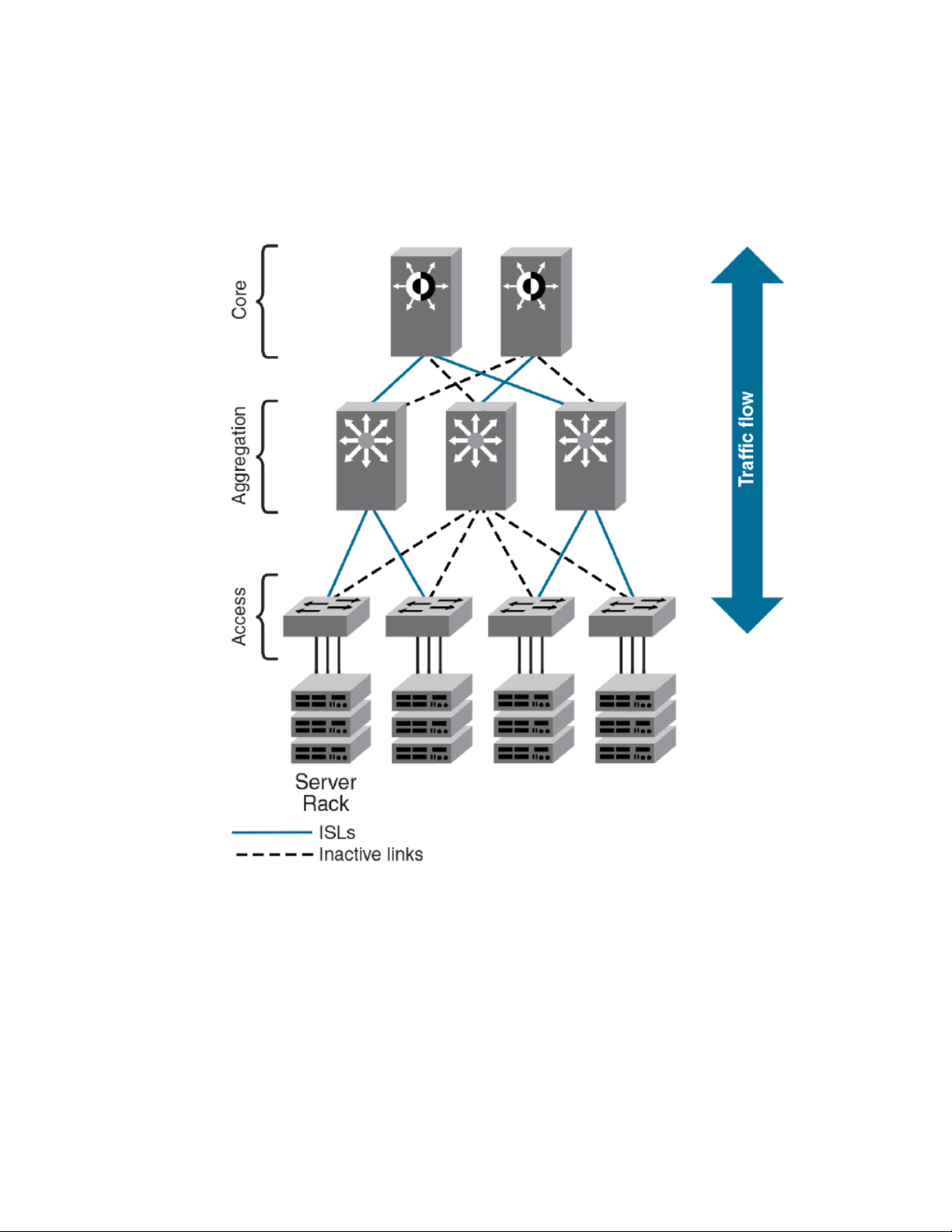
Automation
The following shows an example of a data center with a classic hierarchical Ethernet architecture and
the same data center with a Brocade VCS Fabric architecture. The Brocade VCS Fabric architecture
provides a simpler core-edge topology and is easily scalable as you add more server racks.
FIGURE 1 Comparison of classic Ethernet and Brocade VCS Fabric architectures
Automation
Resilience is a foundational attribute of Brocade Fibre Channel storage networks and resilience is also
a requirement in modern data centers with clustered applications and demanding compute ServiceLevel Agreements (SLAs). In developing its VCS Fabric technology, Brocade naturally carried over this
core characteristic to its Ethernet fabric design.
In traditional Ethernet networks running STP, only 50 percent of the links are active; the rest (shown as
dotted lines in the following figure) act as backups in case the primary connection fails.
When you connect two or more Brocade VCS Fabric mode-enabled switches they form an Ethernet
fabric (provided the two switches have a unique RBridge ID and same VCS ID), as shown below.
Network OS Administrator’s Guide 29
53-1003225-04
Page 30
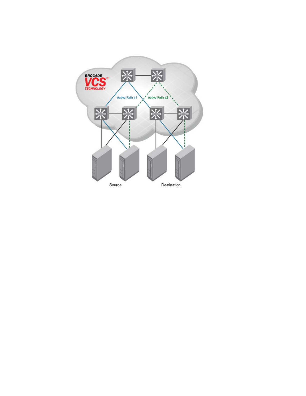
Distributed intelligence
FIGURE 2 Ethernet fabric with multiple paths
The Ethernet fabric has the following characteristics:
• It is a switched network. The Ethernet fabric utilizes an emerging standard called Transparent
Interconnection of Lots of Links (TRILL) as the underlying technology.
• All switches automatically know about each other and all connected physical and logical devices.
• All paths in the fabric are available. Traffic is always distributed across equal-cost paths. As
illustrated above, traffic from the source to the destination can travel across two paths.
• Traffic travels across the shortest path.
• If a single link fails, traffic is automatically rerouted to other available paths. In the topology above, if
one of the links in Active Path #1 goes down, traffic is seamlessly rerouted across Active Path #2.
• Spanning Tree Protocol (STP) is not necessary because the Ethernet fabric appears as a single
logical switch to connected servers, devices, and the rest of the network.
• Traffic can be switched from one Ethernet fabric path to the other Ethernet fabric path.
Distributed intelligence
With Brocade VCS Fabric technology, all relevant information is automatically distributed to each
member switch to provide unified fabric functionality, as illustrated below.
A Brocade VCS fabric is designed to be managed as a single "logical chassis," so that each new
switch inherits the configuration of the fabric, and the new ports become available immediately. The
fabric then appears to the rest of the network as a single switch. This significantly reduces complexity
for the management layer, which in turn improves reliability and reduces troubleshooting.
In addition, VCS fabrics provides a Netconf Application Programming Interfaces (API), as well as
extensions to OpenStack Quantum to orchestrate both physical and logical networking resources as
part of Virtual Machine deployment to support multi-tiered application topologies.
30 Network OS Administrator’s Guide
53-1003225-04
Page 31

FIGURE 3 Distributed intelligence in an Ethernet fabric
Logical chassis
Distributed intelligence has the following characteristics:
• The fabric is self-forming. When two Brocade VCS Fabric mode-enabled switches are connected, the
fabric is automatically created and the switches discover the common fabric configuration.
• The fabric is masterless. No single switch stores configuration information or controls fabric
operations. Any switch can fail or be removed without causing disruptive fabric downtime or delayed
traffic.
• The fabric is aware of all members, devices, and virtual machines (VMs). If the VM moves from one
Brocade VCS Fabric port to another Brocade VCS Fabric port in the same fabric, the port-profile is
automatically moved to the new port, leveraging Brocade’s Automatic Migration of Port Profiles
(AMPP) feature.
Logical chassis
All switches in an Ethernet fabric are managed as if they were a single logical chassis. To the rest of the
network, the fabric looks no different from any other Layer 2 switch. The following illustrates an Ethernet
fabric with two switches. The rest of the network is aware of only the edge ports in the fabric, and is
unaware of the connections within the fabric.
Network OS Administrator’s Guide 31
53-1003225-04
Page 32

Ethernet fabric formation
FIGURE 4 Logical chassis in Ethernet fabric
Each physical switch in the fabric is managed as if it were a blade in a chassis. When a Brocade VCS
Fabric mode-enabled switch is connected to the fabric, it inherits the configuration of the fabric and the
new ports become available immediately.
Ethernet fabric formation
Brocade VCS Fabric protocols are designed to aid the formation of an Ethernet fabric with minimal
user configuration. Refer to Brocade VCS Fabric formation on page 145 for detailed information about
the Ethernet fabric formation process.
All supported switches are shipped with Brocade VCS Fabric mode disabled. Refer to Configuring
Brocade VCS Fabrics on page 145 for information about disabling and enabling Brocade VCS Fabric
mode on your switches.
Automatic neighbor node discovery
When you connect a switch to a Brocade VCS Fabric mode-enabled switch, the Brocade VCS Fabric
mode-enabled switch determines whether the neighbor also has Brocade VCS Fabric mode enabled.
If the switch has Brocade VCS Fabric mode enabled and the VCS IDs match, the switch joins the
Ethernet fabric.
Refer to Configuring Brocade VCS Fabrics on page 145 for information about changing the VCS ID.
32 Network OS Administrator’s Guide
53-1003225-04
Page 33

Automatic ISL formation and hardware-based trunking
Automatic ISL formation and hardware-based trunking
When a switch joins an Ethernet fabric, ISLs automatically form between directly connected switches
within the fabric.
If more than one ISL exists between two switches, then Brocade ISL trunks can form automatically. All
ISLs connected to the same neighboring Brocade switch attempt to form a trunk. The trunks are formed
only when the ports belong to the same port group. No user intervention is necessary to form these
trunks.
Refer to Configuring fabric interfaces on page 150 for information about enabling and disabling ISLs
and trunks.
Principal RBridge election
The RBridge with the lowest WWN in the Ethernet fabric is elected as the principal RBridge.
The role of the principal RBridge is to decide whether a new RBridge joining the fabric conflicts with any
of the RBridge IDs already present in the fabric. If a conflict arises, the principal RBridge keeps the
joining RBridge segmented.
Refer to Configuring a Brocade VCS Fabric on page 148 for information about setting the RBridge ID.
Brocade VCS Fabric technology use cases
This section describes the following use cases for Brocade VCS Fabric technology:
• Classic Ethernet
• Large-scale server virtualization
Classic Ethernet access and aggregation use case
Brocade VCS Fabric can be deployed in the same fashion as existing top-of-rack switches, as shown
below. In the right-most two server racks, a two-switch Ethernet fabric replaces the Ethernet switch at
the top of each rack.
Network OS Administrator’s Guide 33
53-1003225-04
Page 34

Introduction to Network OS and Brocade VCS Fabric Technology
FIGURE 5 Pair of Brocade VDX switches at the top of each server rack
The servers perceive a single top-of-rack switch, allowing for active/active connections running end-toend.
Brocade VCS Fabric technology in this use case provides the following advantages:
• Multiple active-active connections, with increased effective bandwidth
• Preserves existing architecture
• Works with existing core and aggregation networking products
• Co-exists with existing access switches
• Supports 1- and 10-Gbps server connectivity
• Works with server racks or blade servers
34 Network OS Administrator’s Guide
53-1003225-04
Page 35

Large-scale server virtualization use case
Large-scale server virtualization use case
The following shows a logical two-tier architecture with Brocade VCS fabrics at the edge. Each Brocade
VCS fabric appears as a single virtual switch to the switches outside the fabric, which results in
flattening the network.
FIGURE 6 Collapsed, flat Layer 3 networks enabling virtual machine mobility
Brocade VCS Fabric technology in this use case provides the following advantages:
• Optimizes the multipath network (all paths and Layer 3 gateways are active, no single point of failure,
and STP is not necessary)
• Increases sphere of Virtual Machine (VM) mobility
Network OS Administrator’s Guide 35
53-1003225-04
Page 36

Brocade VCS Fabric connectivity with Fibre Channel SAN
Brocade VCS Fabric connectivity with Fibre Channel SAN
In Network OS 2.1.1 and later, Fibre Channel ports on the Brocade VDX 6730 provide support for
connecting a Brocade VCS Fabric to a Fibre Channel SAN. Fibre Channel routers provide the
connectivity, which provides access to Fibre Channel devices while preserving isolation between the
fabrics. Brocade zoning allows you to determine which FCoE devices can access which storage
devices on the Fibre Channel SAN.
Brocade VDX 6730 switches can be deployed into your Brocade VCS Fabric as access-level switches,
aggregation-level switches, or as a means of attachment to Brocade VCS Fabric aggregation-level
switches. Brocade recommends deployment as access-level switches to minimize congestion issues
for storage traffic and isolating FCoE traffic from non-FCoE traffic. The following shows such a
deployment.
FIGURE 7 Brocade VDX 6730 switches deployed as access-level switches
36 Network OS Administrator’s Guide
53-1003225-04
Page 37

Topology and scaling
Up to 24 switches can exist in a Brocade VCS Fabric. Although you can use any network topology to
build a Brocade VCS Fabric, the following topics discuss the scaling, performance, and availability
considerations of topologies more commonly found in data centers:
• Core-edge topology on page 37
• Ring topology on page 38
• Full mesh topology on page 38
Core-edge topology
Core-edge topology, devices connect to edge switches which are connected to each other through core
switches. The example shown below uses three core switches. You could use more or fewer switches
in the core, depending on whether you need higher availably and greater throughput, or a more efficient
use of links and ports.
FIGURE 8 Core-edge topology
Topology and scaling
This topology is reliable, fast, and scales well. It is reliable because it has multiple core switches. If a
core switch or a link to a core switch fails, an alternate path is available. As you increase the number of
core switches, you also increase the number of link or core switch failures your cluster can tolerate.
Network OS Administrator’s Guide 37
53-1003225-04
Page 38

Ring topology
High performance and low latency are ensured because throughput is high and the hop count is low.
Throughput is high because multiple core switches share the load. Two hops get you from any edge
switch to any other edge switch. If you need greater throughput, simply add another core switch.
Scaling the topology also requires additional core switches and links. However, the number of
additional links you need is typically not as great as with, for example, a full mesh topology.
Ring topology
Ring topology connects each node to exactly two other nodes, forming a single continuous pathway.
Data travels from node to node, with each node along the path handling every packet of the data. The
following shows a ring topology.
FIGURE 9 Ring topology
This topology is highly scalable, yet susceptible to failures and traffic congestion. It is highly scalable
because of its efficient use of interswitch links and ports; an additional node requires only two ports to
connect to the ring. It is susceptible to failures because it provides only one path between any two
nodes. Throughput of the fabric is limited by the slowest link or node. Latency can be high because of
the potentially high number of hops it takes to communicates between two given switches. This
topology is useful where economy of port use is critical, but availability and throughput are less critical.
Full mesh topology
Full mesh topology connects each node to all other cluster nodes, as shown below.
38 Network OS Administrator’s Guide
53-1003225-04
Page 39

FIGURE 10 Full mesh topology
Introduction to Network OS and Brocade VCS Fabric Technology
This topology is highly reliable and fast, but it does not scale well. It is reliable because it provides many
paths through the fabric in case of cable or node failure. It is fast with low latency because you can get
to any node in the fabric in just one hop. It does not scale well because each additional node increases
the number of fabric links and switch ports exponentially. This topology is suitable for smaller fabrics
only.
Network OS Administrator’s Guide 39
53-1003225-04
Page 40

Full mesh topology
40 Network OS Administrator’s Guide
53-1003225-04
Page 41

Using the Network OS CLI
● Network OS CLI overview............................................................................................... 41
● Accessing the Network OS CLI through Telnet ..............................................................42
● Saving your configuration changes................................................................................. 42
● Network OS CLI command modes..................................................................................42
● Network OS CLI keyboard shortcuts...............................................................................42
● Using the do command as a shortcut..............................................................................43
● Completing Network OS CLI commands........................................................................ 43
● Displaying Network OS CLI commands and command syntax.......................................44
● Using Network OS CLI command output modifiers.........................................................45
● Considerations for show command output .....................................................................46
Network OS CLI overview
The Brocade Network OS command line interface (CLI) is designed to support the management of Data
Center Bridging (DCB) and Layer 2 Ethernet switching functionality. The Network OS CLI uses an
industry-standard hierarchical shell familiar to Ethernet/IP networking administrators.
The system starts up with the default Network OS configuration and the DCB startup configuration. After
logging in, you are in the Network OS shell. For information on accessing the DCB commands from the
Network OS shell, refer to Network OS CLI command modes on page 42.
Understanding roles
This section discusses the use of roles in Network OS.
RBAC permissions
Role-Based Access Control (RBAC) defines the capabilities that a user account has based on the role
the account has been assigned.
A role is an entity that defines the access privileges of the user accounts on the switch. A user is
associated with one role. Refer to Understanding and managing role-based access control (RBAC) on
page 269 for information about RBAC.
Default roles
Attributes of default roles cannot be modified; however, the default roles can be assigned to non-default
user accounts. The following roles are default roles:
• The admin role has the highest privileges. All CLIs are accessible to the user associated with the
admin role. By default, the admin role has read and write access.
• The user role has limited privileges that are mostly restricted to show commands in privileged EXEC
mode. User accounts associated with the user role cannot access configuration CLIs that are in
global configuration mode. By default, the user role has read-only access.
Network OS Administrator’s Guide
53-1003225-04
41
Page 42

Accessing the Network OS CLI through Telnet
For information on creating a user-defined role, refer to User-defined roles on page 269.
Accessing the Network OS CLI through Telnet
NOTE
While this example uses the admin role to log in to the switch, both roles can be used.
The procedure to access the Network OS CLI is the same through either the console interface or
through a Telnet session; both access methods bring you to the login prompt.
switch login: admin
Password:**********
switch#
Multiple users can open Telnet sessions and issue commands by using privileged EXEC mode.
Network OS 4.0 and later supports up to 32 Telnet sessions with the admin login.
Saving your configuration changes
Any configuration changes made to the switch are written into the running-config file. This is a dynamic
file that is lost when the switch reboots. During the boot sequence, the switch resets all configuration
settings to the values in the startup-config file.
To make your changes permanent, use the copy command to commit the running-config file to the
startup-config file, as shown below.
Here is an example of entering the copy running-config in privileged EXEC mode:
switch# copy running-config startup-config
Network OS CLI command modes
For examples of Network OS CLI command modes, refer to the Network OS Command Reference.
Network OS CLI keyboard shortcuts
The following lists Network OS CLI keyboard shortcuts.
Network OS CLI keyboard shortcuts TABLE 2
Keystroke Description
Ctrl+B (or the left arrow key) Moves the cursor back one character.
Ctrl+F (or the right arrow key) Moves the cursor forward one character.
42 Network OS Administrator’s Guide
53-1003225-04
Page 43

Using the do command as a shortcut
Network OS CLI keyboard shortcuts (Continued)TABLE 2
Keystroke Description
Ctrl+A Moves the cursor to the beginning of the command line.
Ctrl+E Moves the cursor to the end of the command line.
Esc B Moves the cursor back one word.
Esc F Moves the cursor forward one word.
Ctrl+Z Returns to privileged EXEC mode.
Ctrl+P (or the up arrow key) Displays commands in the history buffer with the most recent command
Ctrl+N (or the down arrow key) Displays commands in the history buffer with the most recent command
NOTE
In privileged EXEC mode, use the show history command to list the commands most recently entered.
The switch retains the history of the last 1000 commands entered for the current session.
displayed first.
displayed last.
Using the do command as a shortcut
You can use the do command to save time when you are working in any configuration mode and you
want to run a command in privileged EXEC mode.
For example, if you are configuring LLDP and you want to execute a privileged EXEC mode command,
such as the dir command, you would first have to exit the LLDP configuration mode. By using the do
command with the dir command, you can ignore the need to change configuration modes, as shown in
the following example.
switch(conf-lldp)# do dir
Contents of flash://
-rw-r----- 1276 Wed Feb 4 07:08:49 2009 startup_rmon_config
-rw-r----- 1276 Wed Feb 4 07:10:30 2009 rmon_config
-rw-r----- 1276 Wed Feb 4 07:12:33 2009 rmon_configuration
-rw-r----- 1276 Wed Feb 4 10:48:59 2009 startup-config
Completing Network OS CLI commands
To complete the spelling of commands or keywords automatically, begin typing the command or
keyword and then press Tab. For example, at the CLI command prompt, type te and press Tab:
switch# te
The CLI displays the following command.
switch# terminal
Network OS Administrator’s Guide 43
53-1003225-04
Page 44

Displaying Network OS CLI commands and command syntax
If there is more than one command or keyword associated with the characters typed, the Network OS
CLI displays all choices. For example, at the CLI command prompt, type show l and press Tab.
switch# show l
The CLI displays the following command.
Possible completions:
lacp LACP commands
license Display license keys installed on the switch.
lldp Link Layer Discovery Protocol(LLDP).
logging Show logging
Displaying Network OS CLI commands and command syntax
Enter a question mark (?) in any command mode to display the list of commands available in that
mode.
switch(conf-lldp)# ?
Possible completions:
advertise The Advertise TLV configuration.
description The User description
disable Disable LLDP
do Run an operational-mode command
exit Exit from current mode
hello The Hello Transmit interval.
help Provide help information
iscsi-priority Configure the Ethernet priority to advertise for iSCSI
mode The LLDP mode.
multiplier The Timeout Multiplier
no Negate a command or set its defaults
profile The LLDP Profile table.
pwd Display current mode path
system-description The System Description.
system-name The System Name
top Exit to top level and optionally run command
To display a list of commands that start with the same characters, type the characters followed by the
question mark (? ).
switch# e?
Possible completions:
exit Exit the management session
To display the keywords and arguments associated with a command, enter the keyword followed by
the question mark (?).
switch# terminal ?
Possible completions:
length Sets Terminal Length for this session
monitor Enables terminal monitoring for this session
no Sets Terminal Length for this session to default :24.
timeout Sets the interval that the EXEC command interpreter wait for user input.
If the question mark (?) is typed within an incomplete keyword, and the keyword is the only keyword
starting with those characters, the CLI displays help for that keyword only.
switch# show d?
Possible completions:
debug Debug
diag Show diag related information
dot1x 802.1x configuration
dpod Provides DPOD license information.
If the question mark (?) is typed within an incomplete keyword but the keyword matches several
keywords, the CLI displays help for all the matching keywords.
switch# show i?
interface Interface status and configuration
ip Internet Protocol (IP)
44 Network OS Administrator’s Guide
53-1003225-04
Page 45

Using Network OS CLI command output modifiers
The Network OS CLI accepts abbreviations for commands. This example is the abbreviation for the
show qos interface all command.
switch# sh q i a
If the switch does not recognize a command after Enter is pressed, an error message displays.
switch# hookup
^
syntax error: unknown argument.
If an incomplete command is entered, an error message displays.
switch# show
^
syntax error: unknown argument.
Using Network OS CLI command output modifiers
You can filter the output of the Network OS CLI show commands by using the output modifiers
described below.
Network OS CLI command output modifiers TABLE 3
Output modifier Description
append Appends the output to a file.
redirect Redirects the command output to the specified file.
include Displays the command output that includes the specified expression.
exclude Displays the command output that excludes the specified expression.
begin Displays the command output that begins with the specified expression.
last Displays only the last few lines of the command output.
tee Redirects the command output to the specified file. Notice that this modifier also
until string Ends the output when the output text matches the string.
count Counts the number of lines in the output.
linnum Enumerates the lines in the output.
more Paginates the output.
displays the command output.
nomore Suppresses the pagination of the output.
FLASH Redirects the output to flash memory.
Network OS Administrator’s Guide 45
53-1003225-04
Page 46

Considerations for show command output
Considerations for show command output
Network OS contains many versions of the show command. The output of the show command
changes depending on your configuration and situation. However, in general terms the show
command falls into one of two categories:
• Any show commands that are fabric (global configuration) in nature, such as VLAN, MAC Address
table, AMPP, Zoning, and so on, should display or clear the information for all nodes in a logical
chassis.
• Any show commands that are local to a switch, such as Layer 3 or Layer 2 functionality (for
example, sFlow, SPAN, and so on), should display the local information by default, and display
different switch information specific to an RBridge ID.
46 Network OS Administrator’s Guide
53-1003225-04
Page 47

Basic Switch Management
● Switch management overview........................................................................................ 47
● Ethernet management interfaces.................................................................................... 52
● Stateless IPv6 autoconfiguration.....................................................................................53
● Switch attributes..............................................................................................................54
● Switch types.................................................................................................................... 54
● Operational modes..........................................................................................................55
● Modular platform basics.................................................................................................. 58
● Supported interface modes............................................................................................. 60
● Slot numbering and configuration................................................................................... 61
● Connecting to a switch.................................................................................................... 61
● Using the management VRF...........................................................................................66
● Configuring and managing switches............................................................................... 66
● Configuring policy-based resource management............................................................89
● Brocade support for Openstack...................................................................................... 94
Switch management overview
In addition to connecting to Brocade switches, an understanding of switch types, attributes, and
operational modes is essential to the successful installation and management of networks. This chapter
introduces the operational modes, command modes and submodes, and other switch-related activities
(such as troubleshooting and managing high-availability scenarios), providing an essential reference for
everyday management operations.
Connecting to a switch
You can connect to your switch through a console session on the serial port, or through a Telnet or
Secure Shell (SSH) connection to the management port. You can use any account login present in the
local switch database or on a configured authentication, authorization, and accounting (AAA) server for
authentication. For initial setup procedures, use the preconfigured administrative account that is part of
the default switch configuration.
The switch must be physically connected to the network. If the switch network interface is not
configured or the switch has been disconnected from the network, use a console session on the serial
port.
• Refer to the Brocade VDX Hardware Reference manuals for information on connecting through the
serial port.
• Refer to Configuring Ethernet management interfaces on page 66 for details on configuring the
network interface.
Network OS Administrator’s Guide
53-1003225-04
47
Page 48

Telnet and SSH overview
Telnet and SSH overview
Telnet and Secure Shell (SSH) are mechanisms for allowing secure access to management functions
on a remote networking device. SSH provides a function similar to Telnet, but unlike Telnet, which
offers no security, SSH provides a secure, encrypted connection to the device.
SSH and Telnet support is available in privileged EXEC mode on all Brocade VDX platforms. Both
IPv4 and IPv6 addresses are supported.
Telnet and SSH services are enabled by default on the switch. When the Telnet server or SSH server
is disabled, access to the switch is not allowed for inbound Telnet or SSH connections, thereby
restricting remote access to the switch.
In configuration mode, the CLI can be used to disable Telnet or SSH service on the switch. Doing so
will terminate existing inbound Telnet or SSH connections and block any new inbound Telnet or SSH
connections to the switch. Additional inbound Telnet or SSH connections will not be allowed until the
Telnet server or SSH server is re-enabled. If you have admin privileges, you can re-enable inbound
Telnet or SSH connections from configuration mode.
If you are in logical chassis cluster mode (refer to Operational modes on page 55), the command for
enabling or disabling Telnet or SSH services is not distributed across the cluster. The RBridge ID of
the node should be used to configure the service on individual nodes.
In operational mode, you can use the show command to display whether Telnet or SSH is enabled or
disabled on the switch.
SSH server key exchange and authentication
The Secure Sockets Handling (SSH) protocol allows users to authenticate using public and private key
pairs instead of passwords. In password-based authentication, the user must enter a password for
authentication purposes. In public-key authentication, the user should have a private key in the local
machine and a public key in the remote machine. The user should be logged in to the local machine to
be authenticated. If a passphrase is provided while generating the public and private key pair, it must
be entered to decrypt the private key while getting authenticated.
SSH key-exchange specifies the method used for generating the one-time session keys for encryption
and authentication with the SSH server. A user is allowed to configure the SSH server key-exchange
method to DH Group 14. When the SSH server key-exchange method is configured to DH Group 14,
the SSH connection from a remote SSH client is allowed only if the key-exchange method at the client
is also configured to DH Group 14.
The following steps briefly describe public-key authentication:
1. The user generates a pair of encryption keys in a local machine using the ssh-keygen command,
along with the public and private key (as shown below). Messages encrypted with the private key
can only be decrypted by the public key, and vice-versa.
switch# ssh-keygen -t rsa
generates RSA public and private keypair
switch# ssh-keygen -t dsa
generates DSA public and private keypair
2. The user keeps the private key on the local machine, and uploads the public key to the switch.
3. When attempting to log in to the remote host, the user receives an encrypted message from the
remote host containing the public key. After the message is decrypted in the local host by means of
the private key, the user is authenticated and granted access.
The ssh-keygen command is not distributed across the cluster. The RBridge ID of the node should
be used to configure service on individual nodes.
48 Network OS Administrator’s Guide
53-1003225-04
Page 49

Feature support for Telnet
Feature support for Telnet
The following features are not supported with Telnet:
• Displaying Telnet sessions
• Terminating hung Telnet sessions
Feature support for SSH
SSHv2 is the supported version of SSH, but not all features typically available with SSHv2 are
supported on the Brocade VDX family of switches.
The following encryption algorithms are supported:
• 3des Triple-DES (default)
• aes256-cbc : AES in CBC mode with 256-bit key
• aes192-cbc : AES in CBC mode with 192-bit key
• aes128-cbc : AES in CBC mode with 128-bit key
The following HMAC (Hash-based Message Authentication Code) message authentication algorithms
are supported:
• hmac-md5 : MD5 encryption algorithm with 128-bit key (default).
• hmac-md5-96 : MD5 encryption algorithm with 96-bit key.
• hmac-sha1 : SHA1 encryption algorithm with 160-bit key.
• hmac-sha1-96: SHA1 encryption algorithm with 96-bit key.
SSH user authentication is performed with passwords stored on the device or on an external
authentication, authorization, and accounting (AAA) server.
The following features are not supported with SSH:
• Displaying SSH sessions
• Deleting stale SSH keys
Firmware upgrade and downgrade considerations with Telnet or SSH
Downgrading the firmware on a switch to a Network OS version earlier than 4.0 is not allowed when
either the Telnet server or the SSH server on the switch is disabled. To downgrade to a lower version,
both the Telnet Server and SSH Server must be enabled.
Upgrading to Network OS 4.0 or later is automatically allowed because the Telnet server and SSH
server status are enabled by default.
For more information, refer to Installing and Maintaining Firmware on page 111.
Using DHCP Automatic Deployment (DAD)
DHCP Automatic Deployment (DAD) is a method used to bring up the switch with new firmware or a
preset configuration automatically.
DHCP Automatic Deployment (DAD) is a method used to bring up the switch with new firmware or
preset configuration automatically.
In Network OS 4.1.0 and later, you can automatically bring up a switch with new firmware or a preset
configuration, omitting the need for logging in to the switch console to configure the switch. If you are in
standalone mode or fabric cluster mode, you can apply either the default configuration or a preset
Network OS Administrator’s Guide 49
53-1003225-04
Page 50

Basic Switch Management
configuration. For node replacement in logical chassis cluster mode, the switch is set to the default
configuration.
NOTE
The DAD process is disruptive to traffic.
You must be using DHCP to use DAD. You utilize the DHCP process to retrieve certain parameters
(for example, the firmware path, VCS ID, VCS mode, RBridge ID, and preset configuration file) needed
by the DAD process to perform the firmware and configuration downloads. Currently, only DHCPv4 is
supported.
You must enable DAD from the CLI, after which the switch is rebooted automatically. After the DAD
process is triggered and completed, DAD is automatically disabled. If you attempt to download new
firmware that is already installed on the switch, the DAD process is aborted.
NOTE
If DAD is enabled, you are warned when initiating a firmware download from the CLI that the firmware
download will be unsuccessful.
After a firmware download begins, DAD will report firmware download success or failure status.
DAD depends on DHCP automatic firmware download to load the firmware and configuration onto the
switch. For this to occur, you must first adhere to the following dependencies:
• The management interface of the switch must be set up as DHCP. After setting up the management
• The DHCP server must have the FTP server IP address and configuration file path.
• The configuration file is on the FTP server and it contains the firmware path, new configuration file
DAD supports the following typical use cases:
• Invoking a firmware upgrade (and optional configuration download) on many switches at the same
• Replacing a switch in a cluster by upgrading the firmware and setting up the switch to a preset
Note the following considerations when using DAD:
• The DAD process is disruptive.
• Configuration download is not supported during a firmware downgrade.
• Configurations are not downloaded if the DAD process is aborted due to a sanity check failure, or if
• If an existing firmware download session is either occurring or paused, such as during a firmware
• In-Service Software Upgrade (ISSU) is not supported at this time.
• For dual management module (MM) chassis, the dual MM must be in sync from the chassis bootup
interface on a switch in either standalone or fabric cluster mode, you must use the copy running-
config startup-config for the configuration to take effect.
path, VCS ID, VCS mode, and RBridge ID.
time in standalone and fabric cluster mode.
configuration. (In this instance, DAD must be completed on the new switch hardware (in order to
update the firmware) before the new switch can be incorporated into the cluster.)
you are downloading the same firmware version before the firmware download started.
commit, DAD is not triggered. Instead, the last firmware download session continues. If a firmware
download is in progress and you attempt to enable DAD, you are prompted to try again later.
(not from HA failover). In a chassis system, both MMs are rebooted at the same time.
50 Network OS Administrator’s Guide
53-1003225-04
Page 51

Configuring the DHCP Automatic Deployment process for replacing logical chassis cluster switches
Configuring the DHCP Automatic Deployment process for replacing logical chassis cluster
switches
Provides procedures for configuring DHCP Automatic Deployment (DAD) when replacing switches in
logical chassis cluster mode.
The following procedure configures DHCP Automatic Deployment (DAD) when replacing switches in
logical chassis cluster mode.
1. Disconnect the existing switch from the cluster.
2. Connect the new switch to the cluster. The new switch should be the same model and use the same
cable connection as the old switch.
The new switch should successfully load Network OS 4.1.0. Note, however, that the new switch
cannot join the cluster just yet.
3. From the principal switch, manually run the node replacement with the WWN and RBridge ID.
4. Establish a DAD environment for the new switch. (Make sure DHCP is enabled on the management
interface.)
a) The management interface of the switch must be set up as DHCP. After setting up the
management interface on a switch in either standalone or fabric cluster mode, you must use
the copy running-config startup-config for the configuration to take effect.
b) The DHCP server must have the FTP server IP address and configuration file path.
c) The configuration file is on FTP server and it contains the firmware path, new configuration
file path, VCS ID, VCS mode, and RBridge ID.
d) The DHCP server and FTP server must be up-and-running.
e) DAD must be enabled on the switch using the CLI.
5. Enable DAD by using the dhcp auto-deployment enable command, and enter yes when prompted
to reboot the system.
6. After the new switch is rebooted, DHCP auto-download process downloads the DAD configuration
file to get the VCS mode, VCS ID, and RBridge ID. The RBridge ID should be configured the same
as the previous node in the cluster.
7. The DHCP auto-download process sets the VCS ID and RBridge ID for a switch in logical chassis
cluster mode. No reboot is triggered.
8. The DHCP auto-download process invokes a firmware download if new firmware is detected.
Firmware download completes successfully and the switch comes up with the new firmware and
configuration settings.
NOTE
The DAD process will abort if any error is detected.
9. When the new switch comes up, it will join the cluster with the same configuration as the previous
switch.
10.Use the show dadstatus command to view the current DAD configuration.
Configuring the DAD process for standalone and fabric cluster switches
Provides procedures for configuring DHCP Automatic Deployment (DAD) for switches in standalone
mode or fabric cluster mode.
For the standalone and fabric cluster switches, the DHCP Automatic Deployment (DAD) process is
applicable to both cluster upgrades and node replacement.
The following procedure configures DAD on switches in standalone mode and fabric cluster mode.
Network OS Administrator’s Guide 51
53-1003225-04
Page 52

Telnet and SSH considerations and limitations
1. Establish a DAD environment for the new switch. (Make sure DHCP is enabled on the management
interface.)
a) The management interface of the switch must be set up as DHCP. After setting up the
management interface on a switch in either standalone mode or fabric cluster mode, you
must use the copy running-config startup-config for the configuration to take effect.
b) The DHCP server must have the FTP server IP address and configuration file path.
c) The configuration file is on FTP server and it contains the firmware path, new configuration
file path, VCS ID, VCS mode, and RBridge ID.
d) The DHCP server and FTP server must be up-and-running.
e) DAD must be enabled on the switch using the CLI.
2. Enable DAD by using the dhcp auto-deployment enable command, and enter yes when prompted
to reboot the system.
During system bootup, the DHCP auto-download process downloads the DAD configuration file and
obtains the VCS mode for a standalone switch, and VCS ID and RBridge ID settings for a switch in
fabric cluster mode. The switch configuration is retrieved from the FTP server if one is set up.
NOTE
The DAD process will abort if any error is detected.
3. If node configuration needs to be downloaded, set up the new configuration as the startup
configuration so it will be applied automatically.
The DHCP auto-download process invokes a firmware download if new firmware is detected. After
the firmware download completes successfully, the switch comes up with the new firmware and
configuration settings.
4. Use the show dadstatus command to view the current DAD configuration.
Telnet and SSH considerations and limitations
• Access to the switch is not allowed for both inbound Telnet and SSH connections from both IPv4
and IPv6 addresses when the Telnet or SSH server are disabled.
• Outgoing Telnet or SSH connections from the switch to any remote device is not affected by
disabling or enabling the Telnet or SSH server in the switch.
• No RASLog or auditlog messages are reported when the Telnet or SSH server is disabled or
enabled.
Ethernet management interfaces
The Ethernet network interface provides management access, including direct access to the Network
OS CLI. You must configure at least one IP address using a serial connection to the CLI before you
can manage the system with other management interfaces. You can either configure static IP
addresses, or you can use a Dynamic Host Configuration Protocol (DHCP) client to acquire IP
addresses automatically. For IPv6 addresses, both static IPv6 and stateless IPv6 autoconfiguration
are supported.
ATTENTION
Setting static IP addresses and using DHCP are mutually exclusive. If DHCP is enabled, remove the
DHCP client before you configure a static IP address.
52 Network OS Administrator’s Guide
53-1003225-04
Page 53

Brocade VDX Ethernet interfaces
Brocade VDX Ethernet interfaces
The Brocade VDX compact switches have a single configurable Ethernet interface, Eth0, which can be
configured as a management interface.
The modular chassis, the Brocade VDX 8770-8 and the Brocade VDX 8770-4, have two redundant
management modules, MM1 and MM2. Each management module can communicate with each of the
line cards (interface modules) through an Ethernet connection. Each management module has two
Ethernet interfaces, Eth0 and Eth2.
Eth0 is the management interface and can be configured with an IP address. Eth2 provides connectivity
to the other management module and the line cards in the chassis. The Eth2 IP addressing scheme
uses default IP addresses to communicate between the modules; these addresses are not userconfigurable.
To set a virtual IP address for the chassis, use the chassis virtual-ip command in RBridge ID
configuration mode.
Lights-out management
Lights-out management (LOM) is the ability for a system administrator to monitor and manage servers
by a LOM remote control program.
A complete LOM system consists of a hardware component called the LOM module and a program that
facilitates the continuous monitoring of variables such as microprocessor temperature and utilization.
The program also allows for such remote operations as rebooting, shutdown, troubleshooting, alarm
setting, fan-speed control, and operating system reinstallation.
The modular chassis, the Brocade VDX 8770-8 and the Brocade VDX 8770-4, have two redundant
management modules, MM1 and MM2. Each management module can communicate with each of the
line cards (interface modules) through an Ethernet connection. Each management module has two
Ethernet interfaces, Eth0 and Eth2. These interfaces are also known as Out of Band (OoB)
management interfaces and support LOM programs.
Stateless IPv6 autoconfiguration
IPv6 allows the assignment of multiple IP addresses to each network interface. Each interface is
configured with a link local address in almost all cases, but this address is only accessible from other
hosts on the same network. To provide for wider accessibility, interfaces are typically configured with at
least one additional global scope IPv6 address. IPv6 autoconfiguration allows more IPv6 addresses, the
number of which is dependent on the number of routers serving the local network and the number of
prefixes they advertise.
When IPv6 autoconfiguration is enabled, the platform will engage in stateless IPv6 autoconfiguration.
When IPv6 autoconfiguration is disabled, the platform will relinquish usage of any autoconfigured IPv6
addresses that it may have acquired while IPv6 autoconfiguration was enabled. This same enabled and
disabled state also enables or disables the usage of a link local address for each managed entity
(though a link local address will continue to be generated for each switch) because those link local
addresses are required for router discovery.
The enabled or disabled state of autoconfiguration does not affect any static IPv6 addresses that may
have been configured. Stateless IPv6 autoconfiguration and static IPv6 addresses can coexist.
Network OS Administrator’s Guide 53
53-1003225-04
Page 54

Switch attributes
Switch attributes
A switch can be identified by its IP address, World Wide Name (WWN), switch ID or RBridge ID, or by
its host name and chassis name. You can customize the host name and chassis name with the
switch-attributes command.
• A host name can be from 1 through 30 characters long. It must begin with a letter, and can contain
letters, numbers, and underscore characters. The default host name is "sw0." The host name is
displayed at the system prompt.
• Brocade recommends that you customize the chassis name for each platform. Some system logs
identify the switch by its chassis name; if you assign a meaningful chassis name, logs are more
useful. A chassis name can be from 1 through 30 characters long, must begin with a letter, and can
contain letters, numbers, and underscore characters. The default chassis name is VDX 6710, VDX
6720-24, VDX 6720-60, VDX 6730-32, or VDX 6730-76, VDX 8770-4, or VDX 8770-8 depending on
the switch model.
Switch types
The switchType attribute is a unique device model identifier that is displayed when you issue the show
chassis or the show rbridge-id commands. When you are gathering information for your switch
support provider, you may be asked for the Brocade product name. Use the following to convert the
switchType identifier to a Brocade product name.
Mapping switchType to Brocade product names TABLE 4
switchType Brocade product name Description
95.1 - 95.2 VDX 6720-24 24 1/10-GbE SFP+ ports
96.2 VDX 6730-32 24 1/10-GbE SFP+ ports and 8 8-Gbps FC ports
97.4 VDX 6720-60 60 1/10-GbE SFP+ ports
107.x VDX 6730-76 60 1/10-GbE SFP+ ports and 16 8-Gbps FC ports
112 Management Module Internal component on the switch
113 Switch Fabric Module Internal component on the switch
116.2 VDX 6710-54 48 1-GbE copper and 6 1/10-GbE SFP+ ports
131 VDX 6740 48 10-GbE SFP+ ports and 4 40-GbE QSFP+ ports
137 VDX 6740T 48 10-GbE 10BASE-T ports and 4 40-GbE QSFP+ ports
151 VDX 6740T-1G Same as VDX 6740T, but ships with ports set to 1 GbE
1000.x VDX 8770-4 4 I/O slot chassis supporting 48x1 GbE, 48x10 GbE, 48x10G-T, 12x40
54 Network OS Administrator’s Guide
GbE, 27x40 GbE, or 6x100 GbE line cards
53-1003225-04
Page 55

Mapping switchType to Brocade product names (Continued)TABLE 4
switchType Brocade product name Description
Operational modes
1001.x VDX 8770-8 8 I/O slot chassis supporting 48x1 GbE, 48x10 GbE, 48x10G-T, 12x40
Operational modes
Network OS supports three operational modes for Brocade VDX switches.
The three operational modes are:
• Logical chassis cluster mode — One of two types of "VCS" modes for a switch. This mode requires
Network OS 4.0.0 or later. In this mode, both the data and configuration paths are distributed. The
entire cluster is configured from the principal node. Refer to Logical chassis cluster mode on page
55 for more information.
• Fabric cluster mode — The second of two types of "VCS" modes for a switch. In this mode, the data
path for nodes is distributed, but the configuration path is not distributed. Each node keeps its
configuration database independently. Refer to Fabric cluster mode on page 57 for more
information.
• Standalone mode — Only the Brocade VDX 6710-54, 6720, and 6730 support this mode. Refer to
Standalone mode on page 58 for more information.
When a new switch boots up, the switch enters either standalone mode or fabric cluster mode,
depending on the switch model.
GbE, 27x40 GbE, or 6x100 GbE line cards
ATTENTION
The generic term VCS mode in this manual applies to both fabric cluster mode and logical chassis
cluster mode unless otherwise stated.
Logical chassis cluster mode
Logical chassis cluster mode is defined as a fabric in which both the data and configuration paths are
distributed. The entire cluster must be globally configured from the principal node. Logical chassis
cluster mode requires Network OS 4.0.0 or later.
Logical chassis cluster mode support for platforms
The following platforms support logical chassis cluster mode and is used in any combination:
• Brocade VDX 6710
• Brocade VDX 6720
• Brocade VDX 6730
• Brocade VDX 6740
• Brocade VDX 6740T
• Brocade 6740T-1G
• Brocade VDX 8770-4
• Brocade VDX 8770-8
Network OS Administrator’s Guide 55
53-1003225-04
Page 56

Logical chassis cluster mode characteristics
Logical chassis cluster mode characteristics
The following are the main characteristics of logical chassis cluster mode:
• The maximum number of nodes supported in a logical chassis cluster is 24 for the Brocade VDX
6710, 6720, and 6730; the maximum is 32 for the Brocade VDX 6740, 6740T, 6740T-1G, and 8770.
• Physical connectivity requirements for logical chassis cluster deployment are the same as those for
fabric cluster deployment.
• A single global configuration exists across all nodes, while each node can contain its unique local
configuration. However, each node contains the local configuration information for all other nodes in
the cluster.
• Global and local configurations for the entire logical chassis cluster is performed from one node —
the principal node only.
• Startup configurations are not maintained by the cluster; each node preserves its running
configuration.
• A logical chassis cluster can be transitioned into a fabric cluster while preserving configurations if
you follow the steps provided later in this section
• An existing fabric cluster can be transitioned into a logical chassis cluster while preserving
configurations if you follow the steps provided later in this section
• A node that is a member of a logical chassis cluster can be transitioned to standalone mode.
Platforms that allow standalone mode are the Brocade VDX 6710-54, 6720, and 6730.
• Cluster-wide firmware upgrades can be performed.
• Cluster-wide supportSave can be performed.
Command blocking in logical chassis cluster mode
In logical chassis cluster mode, some commands cannot be run while other commands or events are
processing.
If one of the following CLI command types or events is in progress in the cluster, then any one of the
CLI command types listed below will be rejected until the current command or event has finished.
1. Copy file running-config commands
2. HA failover commands
3. VCS ID/RbridgeID change commands
4. Cluster mode change from logical chassis cluster to fabric cluster
5. Copy default-config startup-config commands
6. Configuration updates by individual commands
7. Cluster formation events, such as initial cluster formation or secondary joining or rejoining of a
cluster
These command and events are considered to be blocked from occurring simultaneously. However, if
the principal node changes during one of these operations or HA failover occurs on principal switch,
the new principal will not retain the information that the commands or events not in progress are in a
blocked state.
In the case of commands being blocked, the following are some of the error messages that could
result:
• Cluster formation is in progress. Please try again later.
• User Configuration update is in progress. Please try again later.
• Configuration file replay is in progress. Please try again later.
• HA failover is in progress in the cluster. Please try again later.
• VCS Config change is in progress in the cluster. Please try again later.
• Copy default-config startup-config is in progress. Please try again later.
56 Network OS Administrator’s Guide
53-1003225-04
Page 57

Logical chassis cluster mode configuration
Logical chassis cluster mode configuration
In logical chassis cluster mode, any operation that results in writing to the configuration database gets
automatically distributed. There are no exceptions.
Each node in the logical chassis cluster maintains an individual copy of the configuration to enable high
availability of the cluster. The following illustrates nodes in a logical chassis cluster. Each node has its
own databases, and the databases kept by each node are identical at all times.
FIGURE 11 Configuration database in a logical chassis cluster
Network OS switches contain both global and local configuration. In a logical chassis cluster, a single
global configuration exists across all cluster members, while each individual member has its own local
configuration. (Conversely, in fabric cluster mode, each cluster member can have its own unique global
configuration.)
Global configuration is required for cluster-wide operations, whereas local configuration is specific to the
operation of an individual node. For more information and examples of each type of configuration, refer
to Examples of global and local configurations on page 81.
Fabric cluster mode
Fabric cluster mode is defined as a fabric in which the data path for nodes is distributed, but the
configuration path is not distributed. Each node keeps its configuration database independently.
By default, the following platforms boot up in fabric cluster mode and will attempt to form Inter-Switch
Links (ISLs):
• Brocade VDX 8770-4
• Brocade VDX 8770-8
Network OS Administrator’s Guide 57
53-1003225-04
Page 58

Standalone mode
• Brocade VDX 6740
• Brocade VDX 6740T
• Brocade VDX 6740T-1G
If the chassis is not connected to another switch, it forms a "single node VCS fabric." This means that
the chassis operates as a standalone system, but the operational mode is always VCS-enabled. You
cannot disable the VCS mode on any of the models listed above.
Standalone mode
All Brocade VDX compact switches (VDX 6710, VDX 6720, and VDX 6730) boot up in standalone
(SA) mode. In this restricted mode, the switch supports only legacy features that were available in
Network OS v2.1.1, with the exception of IP static routes and in-band management. All other Layer 3
features, or any other features introduced in later versions of Network OS are not available in
standalone mode.
NOTE
The Brocade VDX 8770, 6740, 6740T, and 6740T-1G do not support standalone mode.
Modular platform basics
The Brocade VDX 8770 platform features two redundant management modules, three or six switch
fabric modules, and four or eight line cards depending on the switch model. The Brocade VDX 8770-4
supports four line cards and the Brocade VDX 8770-8 supports eight line cards.
The following lists the modules supported on each platform.
Modules supported on the Brocade VDX 8770 platform TABLE 5
Type
MM
SFM 0x71 = 113 S1 - S3 S1 - S6 Switch fabric module (core blade)
LC48X10G 0x72 = 114 L1 - L4 L1 - L8 48-port 10-GbE line card
LC12X40G 0x7F = 127 L1 - L4 L1 - L8 12-port 40-GbE line card
LC48X1G 0x83 = 131 L1 - L4 L1 - L8 48-port 1-GbE line card
LC48X10G-T 0x97 = 151 L1 - L4 L1 - L8 48-port 10 Gbps Base-T line card
Module ID Slot numbers
0x70 = 112 M1, M2 M1, M2 Management module (an 8-core 1.5-GHz Control
VDX 8770-4
Slot numbers
VDX 8770-8
Description
Processor)
LC27X40G 0x96 = 150 L1 - L4 L1 - L8 27-port 40-GbE line card
LC6X100G 0x95 = 149 L1 - L4 L1 - L8 6-port 100-GbE line card
58 Network OS Administrator’s Guide
53-1003225-04
Page 59

Management modules
Management modules
Two management modules (MMs) provide redundancy and act as the main controller on the Brocade
VDX 8770-4 and VDX 8770-8 chassis. The management modules host the distributed Network OS that
provides the overall control plane management for the chassis. You can install a redundant
management module in slot M1 or M2 in any of the Brocade VDX 8770 chassis. By default, the system
considers the module in slot M1 the active management module and the module in slot M2 the
redundant, or standby, management module. If the active module becomes unavailable, the standby
module automatically takes over management of the system.
Each management module maintains its own copy of the configuration database. The startup
configuration is automatically synchronized with the other management module.
Brocade recommends that each management module (primary and secondary partition) should
maintain the same firmware version. For more information on maintaining firmware, refer to Installing
and Maintaining Firmware on page 111.
Each management module has two Ethernet interfaces, Eth0 and Eth2. Eth0 is the management
interface and can be configured with an IP address. For more information on configuring the
management interface, refer to Connecting to a switch on page 47.
HA failover
Warm-recovery HA failover is supported for both fabric cluster mode and logical chassis cluster mode.
Warm recovery includes the following behaviors:
• No data path disruption results for Layer 2 and FCoE traffic.
• All Layer 2 control protocol states are retained.
• The topology state and interface state are retained.
• All running configuration is retained (including the last accepted user configuration just before HA
failover).
• HA Management Module failover may result in data path and control path disruption for the Layer 3
protocol.
• Layer 3 configuration is replayed post-failover.
• During a warm recovery, the principal switch in a logical chassis cluster remains the principal switch.
After warm recovery, the principal switch reestablishes cluster management layer connection with
other switches and reforms the cluster.
• A secondary switch in a logical chassis cluster reestablishes cluster management layer connection
with the principal switch and rejoins the cluster after warm recovery.
• If you run a reload command on an active MM, the principal switch in a logical chassis cluster goes
into cold recovery and comes back up as a secondary switch.
• HA behavior during In-service software upgrades (ISSUs) is the same as for warm-recovery failover.
Support for In-service software upgrades
In-service software upgrades (ISSUs) are supported in Network OS 4.0.0 and later. An ISSU allows a
dual management module system to be upgraded non-disruptively and is invoked by entering the
firmware download command from the active management module.
ISSUs are supported in both fabric cluster mode and logical chassis cluster mode for the following
Network OS upgrade paths:
• 4.0.0 to 4.0.1
• 4.0.0 to 4.1.0
• 4.0.1 to 4.1.0
Network OS Administrator’s Guide 59
53-1003225-04
Page 60

Switch fabric modules
ISSUs are supported in both fabric cluster mode and logical chassis cluster mode for the following
downgrade path: 4.1.0 to 4.0.1
High Availability behavior during ISSUs is the same as that of warm recovery described in HA failover
on page 59. For more information, refer to Upgrading firmware on a modular chassis on page 112.
Switch fabric modules
The switch fabric modules play a dual role in the fabric connectivity between line cards, providing both
the data-plane connectivity and the control-plane connectivity needed for end-to-end credit
management in each of the line cards.
In each chassis model, two slots are designated for supporting the control-plane connectivity. In the
Brocade VDX 8770-4, the slots S1 and S2 are the designated control-plane slots. In the Brocade VDX
8770-8, the slots S3 and S4 are the designated control-plane slots. At least one of the control-plane
slots must be populated to maintain operation. If you remove the switch fabric modules from both the
control-plane slots, all line cards will be faulted and the chassis is no longer operational.
Line cards
The following line cards provide I/O ports for network Ethernet protocols:
• LC48x1G - forty eight 1-GbE/10-GbE SFP+ front ports.
• LC48x10G - forty eight 1-GbE/10-GbE SFP+ front ports.
• LC12x40G - twelve 40-GbE QSFP front ports.
• LC48x10G-T - forty eight 10 Gbps Base-T front ports.
• LC27x40G - twenty seven 40-GbE QSFP front ports.
• LC6x100G - six 100-GbE front ports.
Line card interface ports are named as follows:
• The 10-GbE interfaces are named "TenGigabitEthernet" or "TE".
• The 1-GbE interfaces are named "GigabitEthernet" or "GE".
• The 40-GbE QSFP interfaces are named "FortyGigabitEthernet" or "FO".
Supported interface modes
All interfaces in the Brocade VDX 8770 chassis come online as Fabric Inter-Switch Links ("Fabric
ISLs") by default and will attempt to form a Brocade VCS fabric. If the ISL formation fails, the
interfaces come up as "Edge ports".
NOTE
The Brocade VDX 8770 chassis always comes up in VCS mode. Standalone mode is not supported
on the Brocade VDX 8770 platform.
60 Network OS Administrator’s Guide
53-1003225-04
Page 61

Slot numbering and configuration
The slot number specifies the physical location of a module in a switch or router, and the number of
available slots of each type (interface, management, or switch fabric) depends on the router. Slot
configuration is done on a slot-by-slot basis, and the configurations are stored in a persistent database
on the switch.
Slot numbering
The slot numbering on the Brocade VDX 8770 chassis is based on the module type. The slot numbers
for the line card are numbered L1 through L4 on the Brocade VDX 8770-4, and L1 through L8 on the
Brocade VDX 8770-8. The slots for the management modules are numbered M1 and M2. The slots for
the switch fabric modules are numbered S1 through S3 on the Brocade VDX 8770-4, and S1 through
S6 on the Brocade VDX 8770-8.
Slot configuration
Slot numbering and configuration
Line cards are registered with the system by type, and the slot must be configured with the correct type
before you can install an line card in that slot. When you install a new line card, the system checks
whether or not a previous configuration is associated with the slot. The following rules apply when you
install or replace an line card:
• When you install an line card and boot it up to an online state in a slot that was never occupied or
configured, the module type information is automatically detected and saved to the database. No
special configuration is required.
• If you install an line card in a slot that was previously occupied by an line card of the same type and
the slot is configured for that same type, you can hot-swap the modules without powering off the line
cards. No slot configuration changes are required.
• If the slot was previously configured for a different type of line card, the installation fails and the
module is faulted with a "Type mismatch" error. A RASLog error message is generated. You must
power off the line card and clear the slot configuration with the no linecard command before you can
configure the slot for a new line card.
The slot configuration persists in the database even after the line card is physically removed, powered
off, or faulted since it first came online. All configuration data associated with the slot is automatically
preserved across reboot or hot-swap of the line card with the same type.
Connecting to a switch
You can connect to your switch through a console session on the serial port, or through a Telnet or
Secure Shell (SSH) connection to the management port. You can use any account login present in the
local switch database or on a configured authentication, authorization, and accounting (AAA) server for
authentication. For initial setup procedures, use the preconfigured administrative account that is part of
the default switch configuration.
The switch must be physically connected to the network. If the switch network interface is not
configured or the switch has been disconnected from the network, use a console session on the serial
port.
Network OS Administrator’s Guide 61
53-1003225-04
Page 62

Establishing a physical connection for a Telnet or SSH session
• Refer to the Brocade VDX Hardware Reference manuals for information on connecting through the
serial port.
• Refer to Configuring Ethernet management interfaces on page 66 for details on configuring the
network interface.
Establishing a physical connection for a Telnet or SSH session
1. Connect through a serial port to the switch.
2. Verify that the switch’s network interface is configured and that it is connected to the IP network
through the RJ-45 Ethernet port.
3. Log off the switch’s serial port.
4. From a management station, open a Telnet or SSH connection using the management IP address
of the switch to which you want to connect.
For more information on setting the management IP address, refer to Connecting to a switch on
page 47.
5. Enter the password.
Brocade recommends that you change the default account password when you log in for the first
time. For more information on changing the default password, refer to the Brocade VDX Hardware
Reference manuals.
6. Verify that the login was successful.
The prompt displays the host name followed by a pound sign (#).
switch# login as: admin
admin@10.20.49.112's password:******
---------------------------------------------------WARNING: The default password of 'admin' and 'user' accounts have not been
changed.
Welcome to the Brocade Network Operating System Software
admin connected from 10.110.100.92 using ssh on VDX 6720-24
Telnet services
You can use the Telnet service to connect to a switch.
Establishing a Telnet connection
A Telnet session allows you to access a switch remotely using port 23. However, it is not secure. If
you need a secure connection, use SSH.
1. To establish a Telnet session connection, enter telnet followed by the switch IP address.
switch# telnet 10.17.37.157
If the switch is active and the Telnet service is enabled on it, a display similar to the following will
appear.
Trying 10.17.37.157...
Connected to 10.17.37.157.
Escape character is '^]'.
Network OS (sw0)
switch login:
2. Once you have established the Telnet connection, you can log in normally.
62 Network OS Administrator’s Guide
53-1003225-04
Page 63

Shutting down the Telnet service
NOTE
You can override the default port by using the telnet ip_address command with the optional port
operand (range 0-65535). However, the device must be listening on that port for the connection to
succeed.
The following example overrides the default port.
switch# telnet 10.17.37.157 87
Trying 10.17.37.157...
Connected to 10.17.37.157.
Escape character is '^]'.
Network OS (sw0)
switch# login:
Shutting down the Telnet service
Shutting down the Telnet service will forcibly disconnect all Telnet sessions running on a switch.
You must be in global configuration mode to shut down the Telnet service on a switch.
To shut down the Telnet service on a switch, enter telnet server shutdown.
switch(config)# telnet server shutdown
switch(config)#
All Telnet sessions are immediately terminated, and cannot be re-established until the service is reenabled.
NOTE
If you are in VCS mode, you must enter RBridge ID configuration mode before
issuing the command, as shown in the example below.
switch(config)# rbridge-id 3
switch(config-rbridge-id-3)# telnet server shutdown
Re-enabling the Telnet service
Re-enabling the Telnet service permits Telnet access to a switch.
You must be in global configuration mode to shut down the Telnet service on a switch.
To re-enable the Telnet service on a switch enter no telnet server shutdown.
switch(config)# no telnet server shutdown
NOTE
If you are in VCS mode, you must enter RBridge ID configuration mode before
issuing the command, as shown in the example below.
switch(config)# rbridge-id 3
switch(config-rbridge-id-3)# no telnet server shutdown
Network OS Administrator’s Guide 63
53-1003225-04
Page 64

Connecting with SSH
Connecting with SSH
Connecting to a switch using the SSH (Secure Socket Handling) protocol permits a secure (encrypted)
connection.
For a listing and description of all configuration modes discussed here, refer to Operational modes on
page 55.
Establishing a SSH connection
A SSH (Secure Socket Handling) connection allows you to securely access a switch remotely.
You must be in privileged EXEC mode to make a SSH connection to a switch.
1. To establish an SSH connection with default parameters, enter ssh -l followed by the username you
want to use and the ip_address of the switch.
switch# ssh -l admin 10.20.51.68
2. Enter yes if prompted.
The authenticity of host '10.20.51.68 (10.20.51.68)' can't be established.
RSA key fingerprint is ea:32:38:f7:76:b7:7d:23:dd:a7:25:99:e7:50:87:d0.
Are you sure you want to continue connecting (yes/no)? yes
Warning: Permanently added '10.20.51.68' (RSA) to the list of known hosts.
admin@10.20.51.68's password: ********
WARNING: The default password of 'admin' and 'user' accounts have not been
changed.
Welcome to the Brocade Network Operating System Software
admin connected from 10.20.51.66 using ssh on C60_68F
NOTE
You can use the -m and -c options to override the default encryption and hash
algorithms.
switch# ssh -l admin -m hmac-md5 -c aes128-cbc 10.20.51.68
Importing an SSH public key
Importing an SSH public key allows you to establish an authenticated login for a switch.
You must be in privileged EXEC mode to import an SSH public key to a switch.
1.
NOTE
The following example allows you to import the SSH public key for the user "admin" from a remote
host using the credentials shown.
To import an SSH public key, enter certutil import sshkey, followed by user Username host
IP_Address directory File_Path file Key_filename login Login_ID.
switch# certutil import sshkey user admin host 10.70.4.106 directory /users/
home40/bmeenaks/.ssh file id_rsa.pub login fvt
2. Enter the password for the user.
Password: ***********
switch# 2012/11/14-10:28:58, [SEC-3050], 75,, INFO, VDX6720-60, Event: sshutil,
Status: success, Info: Imported SSH public key from 10.70.4.106 for user 'admin'.
64 Network OS Administrator’s Guide
53-1003225-04
Page 65

Deleting an SSH public key
NOTE
If you are in VCS mode, you must enter RBridge ID configuration mode before
issuing the command, as shown in the example below.
switch# certutil import sshkey user admin host 10.70.4.106 directory /users/home40/
bmeenaks/.ssh file id_rsa.pub login fvt rbridge-id 3
Deleting an SSH public key
Deleting an SSH public key from a switch prevents it from being used for an authenticated login.
You must be in privileged EXEC mode to delete an SSH public key from a switch.
To delete an SSH public key, enter no certutil sshkey user Username followed by either rbridge-id
rbridge-id or rbridge-id all.
switch# no certutil sshkey user admin rbridge-id all
Specifying a specific RBridge ID removes the key from that RBridge ID; specifying all removes it from
all RBridge IDs on the switch.
Shutting down the SSH service
Shutting down the SSH (Secure Socket Handling) service will forcibly disconnect all SSH sessions
running on a switch.
You must be in global configuration mode to shut down the SSH service on a switch.
To shut down the SSH service on a switch, enter ssh server shutdown.
switch(config)# ssh server shutdown
switch(config)#
All SSH sessions are immediately terminated, and cannot be re-established until the service is reenabled.
NOTE
If you are in VCS mode, you must enter RBridge ID configuration mode before
issuing the command, as shown in the example below.
switch(config)# rbridge-id 3
switch(config-rbridge-id-3)# ssh server shutdown
switch(config-rbridge-id-3)#
Network OS Administrator’s Guide 65
53-1003225-04
Page 66

Re-enabling the SSH service
Re-enabling the SSH service
Re-enabling the SSH (Secure Socket Handling) service permits SSH access to a switch.
You must be in global configuration mode to shut down the SSH service on a switch.
To re-enable the SSH service on a switch enter no ssh server shutdown.
switch(config)# no ssh server shutdown
switch(config)#
NOTE
If you are in VCS mode, you must enter RBridge ID configuration mode before
issuing the command, as shown in the example below.
switch(config)# rbridge-id 3
switch(config-rbridge-id-3)# no ssh server shutdown
Using the management VRF
VRF (Virtual Routing and Forwarding) is a technology that controls information flow within a network,
isolating the traffic by partitioning the network into different logical VRF domains. Prior to Network OS
release 5.0.0, routers were managed through the "default" VRF; any port that was part of the default
VRF could be used for router management.
ATTENTION
Beginning with Network OS release 5.0.0, the default VRF and other user-configured (nondefault)
VRFs can no longer be used for router management. Inband management over ports that are part of
the default VRF or another user-configured nondefault VRF are no longer supported. Support is now
provided for the "management" VRF; this is a dedicated, secure VRF instance that allows users to
manage the router inband on switched virtual interfaces (SVIs) and physical interfaces. and that is
allowed only on management VRF ports. For details, as well examples of configuring the management
VRF and the use of a variety of show commands, see Understanding and using the management
VRF.
Configuring and managing switches
The following sections describe how to configure and manage Brocade switches.
Configuring Ethernet management interfaces
The Ethernet network interface provides management access, including direct access to the Network
OS CLI. You must configure at least one IP address using a serial connection to the CLI before you
can manage the system with other management interfaces. You can either configure static IP
addresses, or you can use a Dynamic Host Configuration Protocol (DHCP) client to acquire IP
addresses automatically. For IPv6 addresses, both static IPv6 and stateless IPv6 autoconfiguration
are supported.
66 Network OS Administrator’s Guide
53-1003225-04
Page 67

Configuring static IP addresses
ATTENTION
Setting static IP addresses and using DHCP are mutually exclusive. If DHCP is enabled, remove the
DHCP client before you configure a static IP address.
NOTE
You must connect through the serial port to set the IP address if the network interface is not configured
already. Refer to the Brocade VDX Hardware Reference manual for your specific product for
information on connecting through the serial port.
Configuring static IP addresses
Use static Ethernet network interface addresses in environments where the DHCP service is not
available. To configure a static IPv4 or IPv6 address, you must first disable DHCP. Refer to Configuring
an IPv4 address with DHCP on page 68 for more information.
Configuring a static IPv4 Ethernet address
1. Connect to the switch through the serial console.
2. In privileged EXEC mode, issue the configure terminal command to enter global configuration
mode.
3. Enter the interface management rbridge-id/port command to configure the management port.
This command enters a management interface configuration mode where you can choose
configuration parameters for IPv4 and IPv6 addresses.
• A compact switch has a single management port, and the port number for the management port is
always 0.
• On a modular switch with two redundant management modules, you can configure two
management ports. The port numbers are 1 and 2.
4. Enter the no ip address dhcp command to disable DHCP.
5. Enter the ip address IPv4_address/prefix_length command.
6. Use the ip route 0.0.0.0/0 gw-ip command to configure the gateway address.
NOTE
The ip gateway-address command is not available on the Brocade VDX series if the L3 or
Advanced license is installed. In that case, use the following command sequence:
switch(config)# rbridge-id 1
switch(config-rbridge-id-1)# ip route 0.0.0.0/0 default_gateway_address
7. Verify the configuration with the do show running-config interface management command.
NOTE
Specifying an IPv4 address with a subnet mask is not supported. Instead, enter a prefix number in
Classless Inter-Domain Routing (CIDR) notation. To enter a prefix number for a network mask, type a
forward slash (/) and the number of bits in the mask immediately after the IP address. For example,
Network OS Administrator’s Guide 67
53-1003225-04
Page 68

Configuring a static IPv6 Ethernet address
enter, "209.157.22.99/24" for an IP address that has a network mask with 24 leading 1s in the
network mask, representing 255.255.255.0.
switch(config-Management-1/0)# do show running-config interface management
interface Management 1/0
no ip address dhcp
ip address 10.24.85.81/20
r-bridge-id1
ip route 0.0.0.0/0 10.24.80.1
no ipv6 address autoconfig
8. Apart from the two IP addresses on the management modules, modular switches also supports a
chassis virtual IP address. Using this virtual IP address, you can login to the switch. The VCS virtual
IP address binds to the active MM automatically.
switch(config)# rbridge-id 1
switch(config-rbridge-id-1)# chassis virtual-ip 10.24.85.90/20
NOTE
In DHCP mode, the chassis IP address is obtained by means of DHCP.
Configuring a static IPv6 Ethernet address
1. In privileged EXEC mode, enter the configure terminal command to enter global configuration
mode.
2. Enter the interface management rbridge-id/port command.
This command enters a management interface configuration mode where you can choose
configuration parameters for IPv4 and IPv6 addresses.
• A compact switch has a single management port, and the port number for the management port
is always 0.
• On a modular switches with two redundant management modules, you can configure two
management ports. The port numbers are 1 and 2.
3. Enter the ipv6 address IPv6_addresss/prefix_length command.
switch# configure terminal
Entering configuration mode terminal
switch(config)# interface management 1/0
switch(config-Management-1/0)# ipv6 address fd00:60:69bc:832:e61f:
13ff:fe67:4b94/64
4. Apart from the two IP addresses on the management modules, modular switches also support a
chassis virtual IP address. Using this virtual IP address, you can log in to the switch. The VCS
virtual IP address binds to the active MM automatically.
switch(config)# rbridge-id 1
switch(config-rbridge-id-1)# chassis virtual-ipv6 2001:db8:8086:6502/64
Configuring an IPv4 address with DHCP
NOTE
DHCP is not supported for IPv6 addresses.
By default, DHCP is disabled. You must explicitly enable the service. Use the ip address dhcp
command to enable DHCP for IPv4 addresses, and the ipv6 address dhcp command to enable
DHCP for IPv6 addresses. The Network OS DHCP clients support the following parameters:
• External Ethernet port IP addresses and prefix length
• Default gateway IP address
68 Network OS Administrator’s Guide
53-1003225-04
Page 69

Configuring IPv6 autoconfiguration
NOTE
When you connect the DHCP-enabled switch to the network and power on the switch, the switch
automatically obtains the Ethernet IP address, prefix length, and default gateway address from the
DHCP server. The DHCP client can only connect to a DHCP server on the same subnet as the switch.
Do not enable DHCP if the DHCP server is not on the same subnet as the switch.
The following example enables DHCP for IPv4 addresses.
switch(config)# interface management 1/1
switch(config-Management-1/1)# ip address dhcp
The following example enables DHCP for IPv6 addresses.
switch(config)# interface management 1/1
switch(config-Management-1/1)# ipv6 address dhcp
The show running-config interface management command indicates whether DHCP is enabled. The
following example shows a switch with DHCP enabled for IPv4 addresses.
switch# show running-config interface management
interface Management 2/0
ip address dhcp
ip route 0.0.0.0/0 10.24.80.1
ip address 10.24.73.170/20
no ipv6 address autoconfig
NOTE
Enabling DHCP removes all configured static IP addresses.
Configuring IPv6 autoconfiguration
Refer also to Stateless IPv6 autoconfiguration on page 53.
1. In privileged EXEC mode, issue the configure terminal command to enter global configuration
mode.
2. Take the appropriate action based on whether you want to enable or disable IPv6 autoconfiguration.
• Enter the ipv6 address autoconfig command to enable IPv6 autoconfiguration for all managed
entities on the target platform.
• Enter the no ipv6 address autoconfig command to disable IPv6 autoconfiguration for all
managed entities on the target platform.
NOTE
On the Brocade VDX 8770, the autoconfig command can be issued only on the interface rbridgeid /1. However, this operation enables auto-configuration for the entire chassis.
Displaying the network interface
If an IP address has not been assigned to the network interface, you must connect to the Network OS
CLI using a console session on the serial port. Otherwise, connect to the switch through Telnet or SSH.
Enter the show interface management command to display the management interface.
The following example shows the management interface on a Brocade VDX compact switch.
switch# show interface management
interface Management 9/0
ip address 10.24.81.65/20
ip route 0.0.0.0/0 10.24.80.1
Network OS Administrator’s Guide 69
53-1003225-04
Page 70

Configuring the management interface speed
ipv6 ipv6-address [ ]
ipv6 ipv6-gateways [ fe80::21b:edff:fe0f:bc00 fe80::21b:edff:fe0c:c200 ]
line-speed actual "1000baseT, Duplex: Full"
line-speed configured Auto
The following example shows the management interfaces on a Brocade VDX 8770-4. IPv6
autoconfiguration is enabled for the entire chassis, and, as a result, a stateless IPv6 address is
assigned to both management interfaces.
switch# show interface management
interface Management 110/1
ip address 10.20.238.108/21
ip route 0.0.0.0/0 10.24.80.1
ipv6 ipv6-address [ "stateless fd00:60:69bc:85:205:33ff:fe78:7d88/64 preferred" ]
ipv6 ipv6-gateways [ fe80::21b:edff:fe0b:7800 fe80::21b:edff:fe0b:2400 ]
line-speed actual "1000baseT, Duplex: Full"
line-speed configured Auto
interface Management 110/2
ip address 10.20.238.109/21
ip route 0.0.0.0/0 10.24.80.1
ipv6 ipv6-address [ "stateless fd00:60:69bc:85:205:33ff:fe78:be14/64 preferred" ]
ipv6 ipv6-gateways [ fe80::21b:edff:fe0b:7800 fe80::21b:edff:fe0b:2400 ]
line-speed actual "1000baseT, Duplex: Full"
line-speed configured Auto
Configuring the management interface speed
By default, the speed of the interface is set to autoconfiguration, which means the interface speed is
optimized dynamically depending on load and other factors. You can override the default with a fixed
speed value of 10 Mbps full duplex or 100 Mbps full duplex.
1. In privileged EXEC mode, issue the configure terminal command to enter global configuration
mode.
switch# configure terminal
Entering configuration mode terminal
2. Enter the interface management command followed by rbridge-id/0 .
This command places you in the management interface subconfiguration mode.
switch(config)# interface management 1/0
switch(config-Management-1/0)#
3. Enter the speed command with the selected speed parameter. The valid values are 10, 100, and
auto.
switch(config-Management-1/0)# speed auto
4. Enter the do show interface management command followed by rbridge-id/0 to display the new
settings.
switch(config-Management-1/0)# do show interface management 1/0
interface Management 1/0
ip address 10.24.81.65/20
ip route 0.0.0.0/0 10.24.80.1
ipv6 ipv6-address [ ]
ipv6 ipv6-gateways [fe80::21b:edff:fe0f:bc00 fe80::21b:edff:fe0c:c200]
line-speed actual "1000baseT, Duplex: Full"
line-speed configured Auto
5. Save the configuration changes by using the copy running-config startup-config command.
switch(config-Management-1/0)# do copy running-config startup-config
Configuring a switch banner
A banner is a text message that displays on the switch console. It can contain information about the
switch that an administrator may want users to know when accessing the switch.
The banner can be up to 2048 characters long. To create a multi-line banner, enter the banner login
command followed by the Esc-m keys. Enter Ctrl-D to terminate the input.
If you are in logical chassis cluster mode, the configuration is applied to all nodes in the cluster.
70 Network OS Administrator’s Guide
53-1003225-04
Page 71

Configuring switch attributes
Do the following to set and display a banner.
1. In privileged EXEC mode, issue the configure terminal command to enter global configuration
mode.
2. Enter the banner login command and a text message enclosed in double quotation marks (" ").
3. Enter the do show running-config banner command to display the configured banner.
switch# configure terminal
Entering configuration mode terminal
switch(config)# banner login "Please do not disturb the setup on this switch"
switch(config)# do show running-config banner
banner login "Please do not disturb the setup on this switch"
Use the no banner login command to remove the banner.
Configuring switch attributes
Refer also to:
• Switch attributes on page 54.
• Switch types on page 54.
Setting and displaying the host name
1. In privileged EXEC mode, issue the configure terminal command to enter global configuration
mode.
2. If Telnet is not activated on the switch, enter the no telnet server disable command to activate
Telnet.
3. Enter the switch-attributes command, followed by a question mark (?) to determine the local
RBridge ID.
4. Enter the switch-attributes command, followed by the RBridge ID.
5. Enter the host-name operand, followed by the host name.
6. Save the configuration changes by using the do copy running-config startup-config command.
NOTE
This step is used for switches in standalone mode or fabric cluster mode only. If you are using logical
chassis cluster mode, startup configurations are not maintained by the cluster; each node preserves
its running configuration. For more information about logical chassis cluster mode, refer to Logical
chassis cluster mode on page 55.
7. Verify the configuration with the do show running-config switch-attributes rbridge-id command.
switch# configure terminal
Entering configuration mode terminal
switch(config)# no telnet server disable
switch(config)# switch-attributes ?
Possible completions: <NUMBER:1-239> Specify the rbridge-id 1
switch(config)# switch-attributes 1
switch(config-switch-attributes-1)# host-name lab1_vdx0023
switch(config-switch-attributes-1)# exit
switch(config)# do copy running-config startup-config
switch(config)# do show running-config switch-attributes 1
switch-attributes 1
chassis-name VDX 6720-24
host-name lab1_vdx0023
Network OS Administrator’s Guide 71
53-1003225-04
Page 72

Setting and displaying the chassis name
Setting and displaying the chassis name
1. In privileged EXEC mode, issue the configure terminal command to enter global configuration
mode.
2. Enter the switch-attributes command, followed by a question mark (?) to determine the local
RBridge ID.
3. Enter the switch-attributes command, followed by the RBridge ID.
4. Enter the chassis-name operand, followed by the chassis name.
5. Save the configuration changes using the do copy running-config startup-config command.
NOTE
This step is used for switches in standalone mode or fabric cluster mode only. If you are using
logical chassis cluster mode, startup configurations are not maintained by the cluster; each node
preserves its running configuration. For more information about logical chassis cluster mode, refer
to Logical chassis cluster mode on page 55.
switch# configure terminal
Entering configuration mode terminal
switch(config)# switch-attributes ?
Possible completions: <NUMBER:1-239> Specify the rbridge-id 1
switch(config)# switch-attributes 1
switch(config-switch-attributes-1# chassis-name lab1_vdx0023
switch(config)# do copy running-config startup-config
switch(config)# do show running-config switch-attributes 1
switch-attributes 1
chassis-name lab1_vdx0023
host-name lab1_vdx0023
Viewing switch types
The switchType attribute is a unique device model identifier that allows you to identify the model of a
switch from the command line.
In this example, the number 1000 is the value of the switchType attribute. An optional number (.x)
indicates the revision of the motherboard.
Refer also to Switch types on page 54.
Enter show chassis.
switch# show chassis
Chassis Family: VDX 87xx
Chassis Backplane Revision: 1
switchType: 1000 <== Use table to convert this parameter
(output truncated)
Configuring a switch in logical chassis cluster mode
Refer to Logical chassis cluster mode on page 55.
Creating a logical chassis cluster
This section covers the basic steps to create a logical chassis cluster, with the assumption that all
physical connectivity requirements have been met. The following is a representation of a five-node
logical chassis cluster.
72 Network OS Administrator’s Guide
53-1003225-04
Page 73

Basic Switch Management
FIGURE 12 Five-node logical chassis cluster
To create a logical chassis cluster, follow the steps in the example below:
1. Log into one switch that will be a member of the logical chassis cluster you are creating:
2. In privileged EXEC mode, enter the vcs command with options to set the VCD ID, the RBridge ID
and enable logical chassis mode for the switch. The VCS ID and RBridge IDs shown below are
chosen for the purposes of this example.
switch# vcs vcsid 22 rbridge-id 15 logical-chassis enable
3. The switch reboots after you run the vcs command. You are asked if you want to apply the default
configuration; answer yes.
4. Repeat the above steps for each node in the cluster, changing only the RBridge ID each time. You
must, however, set the VCS ID to the same value on each node that belongs to the cluster.
5. When you have enabled the logical chassis mode on each node in the cluster, run the show vcs
command to determine which node has been assigned as the cluster principal node. The arrow (>)
switch# show vcs
Config Mode : Distributed
VCS Mode : Logical Chassis
VCS ID : 44
VCS GUID : bcab366e-6431-42fe-9af1-c69eb67eaa28
Total Number of Nodes : 3
Rbridge-Id WWN Management IP VCS Status Fabric Status
HostName
--------------------------------------------------------------------------------------------------------
-----144 10:00:00:27:F8:1E:3C:8C 10.18.245.143 Offline Unknown
sw0
152 >10:00:00:05:33:E5:D1:93* 10.18.245.152 Online Online
cz41-h06-m-r2
158 10:00:00:27:F8:F9:63:41 10.18.245.158 Offline Unknown
sw0
denotes the principal node. The asterisk (*) denotes the current logged-in node.
The RBridge ID with the arrow pointing to the WWN is the cluster principal. In this example, RBridge
ID 154 is the principal.
6. Set the clock and time zone for the principal node. Time should be consistent across all the nodes.
Refer to Network Time Protocol overview on page 97.
7. Log in to the principal cluster and make any desired global and local configuration changes. These
changes then are distributed automatically to all nodes in the logical chassis cluster.
NOTE
You can enter the RBridge ID configuration mode for any RBridge in the cluster from the cluster
principal node. You can change the principal node by using the logical-chassis principal priority
and logical chassis principal switchover commands. For more information about cluster principal
nodes, refer to Selecting a principal node for the cluster on page 77.
Network OS Administrator’s Guide 73
53-1003225-04
Page 74

Taking precautions for mode transitions
Taking precautions for mode transitions
Ensure that all nodes to be transitioned are running the same version of Network OS. Logical chassis
cluster mode is supported starting with Network OS release 4.0.0
If you are merging multiple global configuration files to create one new global configuration file, be
sure that the same entity name does not exist in the merged file. For example, if mac access-list
extended test1 contains the entries shown in the "Node 1 global configuration" and "Node 2 global
configuration" below, when you merge the files you can rename mac access-list extended test1 from
Node 2 to mac access-list extended test2 , as shown in the "Combined global configuration."
Node 1 global configuration
mac access-list extended test1
seq 10 permit any 1111.2222.333a ffff.ffff.ffff
seq 20 deny any 1111.2222.333b ffff.ffff.ffff
seq 30 deny any 1111.2222.333c ffff.ffff.ffff
seq 40 permit any any
Node 2 global configuration
mac access-list extended test1
seq 10 permit any 4444.5555.666d ffff.ffff.ffff
seq 20 deny any 4444.5555.666e ffff.ffff.ffff
seq 30 permit any any
Combined global configuration
mac access-list extended test1
seq 10 permit any 1111.2222.333a ffff.ffff.ffff
seq 20 deny any 1111.2222.333b ffff.ffff.ffff
seq 30 deny any 1111.2222.333c ffff.ffff.ffff
seq 40 permit any any
!
mac access-list extended test2
seq 10 permit any 4444.5555.666d ffff.ffff.ffff
seq 20 deny any 4444.5555.666e ffff.ffff.ffff
seq 30 permit any any
The local configuration for Node 2 also needs to be changed accordingly. In this example, one of the
local configuration changes would be the interface TenGigabitEthernet. Instead of referencing test1,
the local configuration file for Node 2 needs to reference test2 because of the change that was made
to the global configuration file. This is shown in the "Node 2 local configuration..." sections below.
Node 2 local configuration before matching the combined global configuration
interface TenGigabitEthernet 4/0/3
fabric isl enable
fabric trunk enable
switchport
switchport mode access
switchport access vlan 1
spanning-tree shutdown
mac access-group test1 in
no shutdown
Node 2 local configuration after matching the combined global configuration
interface TenGigabitEthernet 4/0/3
fabric isl enable
fabric trunk enable
switchport
switchport mode access
switchport access vlan 1
74 Network OS Administrator’s Guide
53-1003225-04
Page 75

Converting a fabric cluster to a logical chassis cluster
spanning-tree shutdown
mac access-group test2 in
no shutdown
ATTENTION
Be sure to take the following precautions.
• Note that the copy default-config to startup-config command in logical chassis cluster mode
causes a cluster-wide reboot and returns the entire logical chassis cluster to the default
configuration. Therefore, use this command only if you want to purge all existing configuration in the
logical chassis cluster.
• Make sure that the backup files for global and local configurations are available in a proper SCP or
FTP location that can be easily retrieved in logical chassis cluster mode during restore. Do not save
the files in the local flash, because they may not be available on the principal node for replay of local
configurations.
Converting a fabric cluster to a logical chassis cluster
You can convert an existing fabric cluster to a logical chassis cluster using the default configuration file.
1. Be sure all nodes are running the same firmware version. Logical chassis cluster functionality is
supported in Network OS 4.0.0 and later.
2. Be sure all the nodes that you intend to transition from a fabric cluster to a logical chassis cluster are
online. Run either the show vcs or show vcs detail command to check the status of the nodes.
3. Log into one switch that you are converting from fabric cluster mode to logical chassis cluster mode.
4. In Privileged EXEC mode, enter the vcs logical-chassis enable command with desired options; for
example you can convert all RBridges with one command:
switch# vcs logical-chassis enable rbridge-id all default-config
NOTE
To convert a specific RBridge from fabric cluster mode to logical chassis mode, use the RBridge ID
value in place of the "all" option. You can also specify a range, such as "1,3,4-6". Refer to the
Network OS Command Reference for details.
The nodes automatically reboot in logical chassis cluster mode. Allow for some down time during the
mode transition.
5. Run either the show vcs or the show vcs detail command to check that all nodes are online and
now in logical chassis cluster (listed as "Distributed" in the command output) mode.
6. The show vcs command output can also be used to determine which node has been assigned as
the cluster principal node.
switch# show vcs
R-Bridge WWN Switch-MAC Status
___________________________________________________________________
1 > 11:22:33:44:55:66:77:81 AA:BB:CC::DD:EE:F1 Online
2 11:22:33:44:55:66:77:82 AA:BB:CC::DD:EE:F2 Online
3 11:22:33:44:55:66:77:83* AA:BB:CC::DD:EE:F3 Online
The RBridge ID with the arrow pointing to the WWN is the cluster principal. In this example, RBridge
ID 1 is the principal.
7. Log in to the principal cluster and make any desired global and local configuration changes. These
changes then are distributed automatically to all nodes in the logical chassis cluster.
Network OS Administrator’s Guide 75
53-1003225-04
Page 76

Converting a fabric cluster while preserving configuration
NOTE
You can enter the RBridge ID configuration mode for any RBridge in the cluster from the cluster
principal node.
NOTE
You can change the principal node by using the logical-chassis principal priority and logical
chassis principal switchover commands. For more information about cluster principal nodes,
refer to Selecting a principal node for the cluster on page 77.
Converting a fabric cluster while preserving configuration
There is no specific command that can convert a fabric cluster to a logical chassis cluster while
preserving current configurations, but you can accomplish this task as follows:
1. Be sure that all nodes are running the same firmware version. Logical chassis cluster functionality is
supported in Network OS 4.0 and later.
2. Make sure all the nodes that you intend to transition from a fabric cluster to a logical chassis cluster
are online. Run either the show vcs or show vcs detail command to check the status of the nodes.
3. Determine which node contains the global configuration you want to use on the logical chassis
cluster, and make a backup of this configuration by running the copy global-running-config
command and saving the configuration to a file on a remote ftp, scp, sftp or usb location:
NOTE
If you need to combine the global configurations of two or more nodes, manually combine the
required files into a single file which will be replayed after the transition to logical chassis cluster
mode by using the copy global-running-config location_config_filename command. Refer to the
section Taking precautions for mode transitions on page 74
4. Back up the local configurations of all individual nodes in the cluster, by running the copy local-
running-config command on each node and saving the configuration to a file on a remote ftp, scp,
sftp, or usb location:
copy local-running-config location_config_filename
5. Perform the mode transition from fabric cluster to logical chassis cluster by running the vcs logicalchassis enable rbridge-id all default-config command, as shown in Converting a fabric cluster to
a logical chassis cluster on page 75.
The nodes automatically reboot in logical chassis cluster mode. Allow for some down time during
the mode transition.
6. Run either the show vcs or the show vcs detail command to check that all nodes are online and
now in logical chassis cluster (listed as "Distributed" in the command output) mode.
7. The show vcs command output can also be used to determine which node has been assigned as
the cluster principal node.
switch# show vcs
R-Bridge WWN Switch-MAC Status
___________________________________________________________________
1 > 11:22:33:44:55:66:77:81 AA:BB:CC::DD:EE:F1 Online
2 11:22:33:44:55:66:77:82 AA:BB:CC::DD:EE:F2 Online
3 11:22:33:44:55:66:77:83* AA:BB:CC::DD:EE:F3 Online
The RBridge ID with the arrow pointing to the WWN is the cluster principal. In this example, RBridge
ID 1 is the principal.
8. While logged on to the principal node in the logical chassis cluster, copy the saved global
configuration file from the remote location to the principal node as follows:
copy location_config_filename running-config
76 Network OS Administrator’s Guide
53-1003225-04
Page 77

Selecting a principal node for the cluster
9. Verify that the global configuration is available by running the show global-running-config
command.
10.While logged on to the principal node in the logical chassis cluster, copy each saved local
configuration file from the remote location to the principal node as follows:
copy location_config_filename running-config
NOTE
You must run this command for each local configuration file you saved (one for each node).
The configuration file is automatically distributed to all nodes in the logical chassis cluster. Each node
will contain the same global configuration after the above steps are performed. Each node will also
contain the local configuration information of all the other nodes.
11.Verify that the local configurations are available by running the show local-running-config
command.
12.Log in to the principal cluster and make any desired global and local configuration changes. These
changes then are distributed automatically to all nodes in the logical chassis cluster.
NOTE
You can enter the RBridge ID configuration mode for any RBridge in the cluster from the cluster
principal node. You can change the principal node by using the logical-chassis principal priority
and logical chassis principal switchover commands. For more information about cluster principal
nodes, refer to Selecting a principal node for the cluster on page 77.
Selecting a principal node for the cluster
Logical chassis cluster principal node behavior includes:
• All configuration for the logical chassis cluster must be performed on the principal node.
• By default, the node with the lowest WWN number becomes the principal node.
• You can run the show vcs command to determine which node is the principal node. An arrow in the
display from this command points to the WWN of the principal node.
• You can select any node in the logical chassis cluster to become the principal by running the logical
chassis principal priority command, followed by the logical-chassis principal switchover
command, as shown in the following example (in this example, RBridge ID 5 is being assigned with
the highest priority):
switch# configure
switch(config)# rbridge-id 5
switch(config-rbridge-id-5)# logical-chassis principal-priority 1
switch(config-rbridge-id-5)# end
switch# logical-chassis principal-switchover
A lower number means a higher priority. Values range from 1 to 128.
Until you run the logical-chassis principal switchover command, the election of the new principal
node does not take effect.
Converting a logical chassis cluster to a fabric cluster
To transition all nodes in a logical chassis cluster to a fabric cluster, using default configurations,
perform these steps:
1. Make sure all the nodes that you intend to transition from a logical chassis cluster to a fabric cluster
are online. Run either the show vcs or show vcs detail command to check the status of the nodes.
2. Log in to the principal node on the logical chassis cluster.
Network OS Administrator’s Guide 77
53-1003225-04
Page 78

Converting to a fabric cluster while preserving configuration
3. Run the following command to convert all RBridge IDs: no vcs logical-chassis enable rbridge-id
all default-config.
NOTE
To convert just one RBridge ID, specify the ID as shown in the following example: no vcs logicalchassis enable rbridge-id rbridge-id default-config.
The nodes automatically reboot in fabric cluster mode. Plan for some down time for this transition.
4. Run either the show vcs or show vcs detail command to check that all nodes are online and now
in fabric cluster (listed as "Local-only" in the command output) mode.
Converting to a fabric cluster while preserving configuration
There is no specific command that can convert a logical chassis cluster to a fabric cluster while
preserving current configurations, but you can accomplish this task as follows:
1. Make sure all the nodes that you intend to transition from a logical chassis cluster to a fabric cluster
are online. Run either the show vcs or show vcs detail command to check the status of the nodes.
2. Back up the configurations of all nodes in the cluster by running the copy rbridge-running-config
rbridge-id command on each node and saving the configuration to a file on a remote ftp, scp, sftp,
or usb location:
copy rbridge-running-config rbridge-id rbridge-id location_configfilename
This command copies both the global and local configurations for the specified RBridge ID.
3. From the principal node of the logical chassis cluster, transition the entire cluster to fabric cluster
mode (using the default configuration) by running the following command:
no vcs logical-chassis enable rbridge-id all default-config
The nodes automatically reboot in fabric cluster mode. Plan for some down time for this transition.
4. Run either the show vcs or show vcs detail command to check that all nodes are online and now
in fabric cluster (listed as "Local-only" in the command output) mode.
5. Restore the global and local configurations on each individual node for which you backed up these
configurations by running the following command on each node:
copy location_configfilename running-config
6. To cause this downloaded configuration to be persistent for a node, run the copy running-config
startup-config command.
Adding a node to a logical chassis cluster
Nodes can be dynamically added to an existing logical chassis cluster. If the proper physical
connections exist between the existing logical chassis cluster and the new node, the process is
automatic.
Log into the new node and run the vcs logical-chassis enable command with the desired options.
You must assign the new node the VCS ID of the existing cluster.
You can run the show vcs command to verify that the status of the added node is "online."
Removing a node from a logical chassis cluster
If the no vcs enable command is executed on a switch that is currently in logical chassis cluster
mode, the switch boots in standalone mode. (Only the Brocade VDS 6710-54, 6720, and 6730 support
78 Network OS Administrator’s Guide
53-1003225-04
Page 79

Rejoining a node to the cluster
standalone mode.) If the no vcs logical-chassis enable command is executed on a switch that is
currently in logical chassis cluster mode, the switch boots in fabric cluster mode.
Once the node is removed, all configurations corresponding to that node are removed from the cluster
configuration database. Similarly, the removed node does not retain any configurations corresponding
to the other nodes in the cluster.
The following shows the cluster after node N5 has been removed. Nodes N1 through N4 remain in the
cluster, and N5 is an island. There is no data path or management path connectivity between the two
islands.
FIGURE 13 Removal of Node N5 from the logical chassis cluster
Rejoining a node to the cluster
Nodes that are temporarily isolated from a logical chassis cluster can re-join the cluster as long as no
configuration or cluster membership changes have taken place on either the deleted node or the
cluster. Run the vcs logical-chassis enable command with the desired options to rejoin the node to
the cluster.
However, if configuration changes have occurred on either the node or cluster since the node was
removed, you must reboot the node with its default configuration by issuing copy default-config
startup-config on the segmented node.
Replacing a node in a logical chassis cluster
If a node in a logical chassis cluster becomes damaged and no longer be used, a similar node with
identical capabilities can be used in its place.
The new node must use the same RBridge ID of the node that is being replaced. When the new node is
detected, it joins the cluster as a previously known node instead of being considered a new node.
To replace a node that has an RBridge ID of 3 and then enter the WWN of the new node, follow the
steps shown in the following example:
1. Run the following command on the principal switch:
switch# vcs replace rbridge-id 3
Enter the WWN of the new replacement switch: 11:22:33:44:55:66:77:81
2. Assign the RBridge ID of 3 to the new node by running the following command on the new node,
assuming the new node is already VCS enabled:
switch# vcs rbridge-id 3
Network OS Administrator’s Guide 79
53-1003225-04
Page 80

Merging two logical chassis clusters
NOTE
If the new node is not yet VCS enabled, you can do so at the same time you assign the RBridge ID.
Refer to the vcs command options in the Network OS Command Reference.
Merging two logical chassis clusters
You can merge two logical chassis clusters that have the same VCS ID. Follow these steps:
1. Make all required physical connections between the two independent clusters.
2. Decide which cluster should retain the configuration after the merge. Only one configuration can be
retained.
3. On the cluster whose configuration will not be retained, issue the copy default-config startup-
config command so that the nodes in this cluster will reboot with the default configuration.
4. Reboot all nodes in each cluster. The logical chassis cluster whose configuration is being retained
recognizes the nodes from the other cluster as new nodes and adds them accordingly.
5. Re-apply the configuration to the cluster whose configuration was not retained.
Changing an RBridge ID on a switch within a fabric
It may become necessary to change the RBridge ID number on a switch that rebooted and has
become orphaned from the cluster.
1. Backup the global configuration before changing the RBridge ID, because the local configuration
will be reset to default values. Refer to Backing up configurations on page 104.
2. On the rebooted switch, execute the chassis disable command.
switch# chassis disable
3. From the fabric principal switch, execute the no vcs enable rbridge-id rbridge-id command, where
rbridge-id is the switch that was orphaned.
switch# no vcs enable rbridge-id 3
4. On the rebooted switch, execute the vcs rbridge-id rbridge-id command, where rbridge-id is the
RBridge you want to use.
5. The VCSID should already be set, if it's not set it with the vcs rbridge-id rbridge-id.
6. Reboot the orphaned switch.
The following behavior will take effect after the switch reboots:
• All interfaces will be in shutdown state. You must perform a no shutdown command on ISL
interfaces before the switch will rejoin the cluster.
• The original configuration will be lost and the switch will have a default configuration when it
rejoins the cluster with the new RBridge ID.
7. Use the show vcs detail command to verify that the switch is in the fabric.
switch# show vcs detail
Config Mode : Local-Only
VCS ID : 1
Total Number of Nodes : 6
Node :1
Serial Number : BKN2501G00R
Condition : Good
Status : Connected to Cluster
VCS Id : 1
Rbridge-Id : 38
Co-ordinator : NO
WWN : 10:00:00:05:33:52:2A:82
Switch MAC : 00:05:33:52:2A:82
FCF MAC : 0B:20:B0:64:10:27
Switch Type : BR-VDX6720-24-C-24
Internal IP : 127.1.0.38
Management IP : 10.17.10.38
Node :2
Serial Number : BZA0330G00P
80 Network OS Administrator’s Guide
53-1003225-04
Page 81

Examples of global and local configurations
Examples of global and local configurations
The table below provides examples of global and local configuration commands that are available under
the respective configuration modes. These settings can be viewed respectively by means of the show
global-running-config command and the show local-running-config command.
Global and local configuration commandsTABLE 6
Global Local
Interface vlan switch-attributes
interface port-channel interface management
port-profile interface ve
mac access-list diag post
ip access-list dpod
sflow switch-attributes
snmp-server fabric route mcast
protocol lldp rbridge-id
zoning ip route
cee-map linecard
username router ospf
router bgp
protocol vrrp
vrrp-group
interface management
interface gigabitethernet
interface tengigabitethernet
interface fortygigabitethernet
interface fcoe
Use the copy snapshot commands if you need to upload or download configuration snapshot files to
and from an ftp or scp server. You may need to use these commands if you took a snapshot of a
configuration on a node that was disconnected from the cluster.
Refer to the Network OS Command Reference for detailed information about these and other logical
chassis server commands.
Network OS Administrator’s Guide 81
53-1003225-04
Page 82

Configuring a switch in fabric cluster mode
Configuring a switch in fabric cluster mode
Refer also to Fabric cluster mode on page 57. When you issue the show vcs command to display the
VCS configuration for the chassis, the command output shows a single-node VCS with a VCS ID of 1
and an RBridge ID of 1. Use the vcs command to change the default values.
switch0# show vcs
Config Mode : Local-Only
VCS ID : 1
Total Number of Nodes : 1
Rbridge-Id WWN Management IP VCS Status Fabric Status HostName
------------------------------------------------------------------------------------
1 >10:00:00:05:33:51:63:42* 10.17.37.154 Online Online switch0
2607:f0d0:1002:ff51:ffff:ffff:ffff:fff5
Configuring a switch in standalone mode
When you display the VCS configuration for a compact switch in default mode, it shows that VCS
mode is disabled. Always confirm the status of a switch before making configuration changes.
switch# show vcs
state: Disabled
Refer also to Standalone mode on page 58.
Displaying switch interfaces
Interfaces on the VDX 8770 platform are identified by the RBridge ID, slot number, and port number,
separated by forward slashes (/). For example, the notation 9/2/8 indicates port 8 located in slot 2 on a
chassis with the RBridge ID of 9.
Enter the show running-config interface interface_type command to display the interfaces and their
status.
switch# show running-config interface tengigabitethernet
interface tengigabitethernet 1/1/1
fabric isl enable
fabric trunk enable
no shutdown
!
interface tengigabitethernet 1/1/2
fabric isl enable
fabric trunk enable
no shutdown
!
interface tengigabitethernet 1/1/3
fabric isl enable
fabric trunk enable
no shutdown
!
interface tengigabitethernet 1/1/4
fabric isl enable
fabric trunk enable
no shutdown
!
interface tengigabitethernet 1/1/5
fabric isl enable
fabric trunk enable
no shutdown
!
interface tengigabitethernet 1/1/6
fabric isl enable
fabric trunk enable
no shutdown
82 Network OS Administrator’s Guide
53-1003225-04
Page 83

Displaying slots and module status information
Enter the show interface interface_type rbridge_id/slot/port command to display the configuration
details for the specified interface.
switch# show interface tengigabitethernet 1/1/9
tengigabitethernet 1/1/9 is up, line protocol is up (connected)
Hardware is Ethernet, address is 0005.3315.df5a
Current address is 0005.3315.df5a
Pluggable media present
Interface index (ifindex) is 4702109825
MTU 9216 bytes
LineSpeed Actual : 10000 Mbit
LineSpeed Configured : Auto, Duplex: Full
Flowcontrol rx: off, tx: off
Priority Tag disable
Last clearing of show interface counters: 04:12:03
Queueing strategy: fifo
Receive Statistics:
1580 packets, 140248 bytes
Unicasts: 0, Multicasts: 1580, Broadcasts: 0
64-byte pkts: 0, Over 64-byte pkts: 1561, Over 127-byte pkts: 17
Over 255-byte pkts: 2, Over 511-byte pkts: 0, Over 1023-byte pkts: 0
Over 1518-byte pkts(Jumbo): 0
Runts: 0, Jabbers: 0, CRC: 0, Overruns: 0
Errors: 0, Discards: 0, TrillportCtrlFrames: 1564
Transmit Statistics:
1583 packets, 140120 bytes
Unicasts: 0, Multicasts: 1583, Broadcasts: 0
Underruns: 0
Errors: 0, Discards: 0, TrillportCtrlFrames: 1583
Rate info (interval 299 seconds):
Input 0.000000 Mbits/sec, 0 packets/sec, 0.00% of line-rate
Output 0.000000 Mbits/sec, 0 packets/sec, 0.00% of line-rate
Time since last interface status change: 00:15:53
Refer also to Slot numbering and configuration on page 61.
Displaying slots and module status information
Use the show slots command to display information for all slots in the chassis. The following example
shows slot information for the Brocade VDX 8770-8.
switch# show slots
Slot Type Description ID Status
--------------------------------------------------------------------------M1 MM Management Module 112 ENABLED
M2 MM Management Module 112 ENABLED
S1 SFM Switch Fabric Module 113 ENABLED
S2 VACANT@
S3 SFM Switch Fabric Module 113 ENABLED#
S4 SFM Switch Fabric Module 113 ENABLED#
S5 SFM Switch Fabric Module 113 ENABLED
S6 SFM Switch Fabric Module 113 ENABLED
L1 VACANT
L2 VACANT
L3 LC48X10G 48-port 10GE card 114 DIAG RUNNING POST1
L4 LC48X10G 48-port 10GE card 114 ENABLED
L5 VACANT
L6 VACANT
L7 LC48X1G 48-port 1GE card 114 ENABLED
L7 VACANT
L8 VACANT
# = At least one enabled SFM in these slots is required.
@ = The SFM Optical Switch is open.
Alternatively, you can use the following commands to display slots per module type:
• Use the show mm command to display information for the management modules.
• Use the show sfm command to display information for the switch fabric modules.
• Use the show linecard command to display information for the line cards.
To make the slot configuration persistent across a chassis reboot (which involves reloading the
management modules), you must save the configuration persistently by issuing the copy running-
Network OS Administrator’s Guide 83
53-1003225-04
Page 84

Replacing a line card
config startup-config command after the line card reaches the online state and before the system
reboots.
Replacing a line card
You can remove a line card without powering it off. However, doing so will not remove the
configuration. When you replace a card with a different type, you must first remove the configuration
and then reconfigure the slot for the new line card type.
Install a new line card only if it is supported by the firmware running in the chassis. Inserting a line card
into a chassis running firmware that does not support the line card may result in unexpected behavior.
Do the following to replace a line card.
CAUTION
Removing the configuration requires the card to be powered off.
1. Power off the line card by issuing the power-off linecard command followed by the slot number.
2. Enter the configure terminal command to enter global configuration mode.
3. Enter the rbridge-id rbridge-id command to enter RBridge ID configuration mode.
4. Enter the no linecard slot_number command to clear the slot configuration.
5. Remove the line card.
6. Enter the linecard slot_number command followed by a question mark (?) to display the line card
menu.
7. Select a line card type and enter the linecard slot_number linecard_type command.
8. Enter the exit command twice to return to privileged EXEC mode.
9. Insert the new line card into the configured slot.
10.Enter the power-on linecard command to power on the line card.
11.Save the configuration persistently by issuing the copy running-config startup-config command
after the line card reaches the online state.
12.Verify the configuration with the show running-config linecard linecard command.
switch# power-off linecard 4
switch# configure terminal
Entering configuration mode terminal
switch(config)# rbridge-id 1
switch(config-rbridge-id-1)# no linecard 4
switch(config-rbridge-id-1)# linecard 4 ?
Possible completions:
LC12x40G 12X40G linecard
LC48x1G 48X1G linecard
LC48x10G 48X10G linecard
LC72x1G 72X1G linecard
LC48x10GT 48X10G Base-T linecard
LC27X40G 27X40G linecard
LC6X100G 6X100G linecard
switch(config-rbridge-id-1)# linecard 4 LC48x10G
Creating new linecard configuration was successful.
switch(config-rbridge-id-1)# exit
switch(config)# exit
switch# copy running-config startup-config
switch# show running-config rbridge-id 4 linecard
rbridge-id 1
linecard 1 LC48x10G
linecard 4 LC48x10G
84 Network OS Administrator’s Guide
53-1003225-04
Page 85

Configuring high availability
Configuring high availability
The following sections provide you with information on configuring High Availability (HA) support on
Brocade switches.
Using HA commands
A variety of high-availability (HA) commands are available on the switch in privileged EXEC mode.
• show ha displays the management module status.
switch# show ha
Local (M2): Active, Cold Recovered
Remote (M1): Standby, Healthy
HA enabled, Heartbeat Up, HA State synchronized
• ha failover forces the active management module to fail over. The standby management module will
take over as the active management module.
• reload system reboots the entire chassis. This command is supported only on the active
management module. This command is not supported on the standby management module. Both
management modules must be in sync for the HA reboot operation to succeed. In logical chassis
cluster mode, this command can be issued from the principal node to reset one remote node or all of
the remote nodes by specifying either the individual rbridge-id or "all".
• ha sync start enables HA state synchronization after an ha sync stop command has been invoked.
• show ha all-partitions displays details for all line cards and the MM HA state.
NOTE
For additional HA commands and related commands, refer to the Network OS Command Reference
Understanding expected behaviors for reload and failover
The following tables identify expected behaviors that result from controlled and uncontrolled reload and
failover conditions.
Expected behaviors for controlled reload and failoverTABLE 7
Command syntax Behavior in fabric cluster and logical chassis cluster
reload Cold failover to standby management module (MM).
NOTE
When MMs are out of sync, the reload command does not work. Use the reload system
command to reboot the switch in this case.
reload standby Reboot the standby MM.
reload system Reboot both MMs. MMs will retain the HA roles.
ha failover Warm failover to standby MM.
Network OS Administrator’s Guide 85
53-1003225-04
Page 86

Disabling and enabling a chassis
Command syntax Behavior in fabric cluster and logical chassis cluster
Panic Warm failover to standby MM.
MM removal Warm failover to standby MM.
Power cycle MMs will retain the HA roles upon booting up.
Disabling and enabling a chassis
The chassis is enabled after power is turned on, and diagnostics and switch initialization routines have
finished. All interfaces are online. You can disable and re-enable the chassis as necessary.
• Use the chassis disable command if you want to take all interfaces offline. If the switch was part of
an Ethernet fabric, the fabric reconfigures.
• Use the chassis enable command to bring the interfaces back online. All interfaces that were
enabled before the chassis was disabled are expected to come back online. If the switch was part
of an Ethernet fabric, it rejoins the fabric.
Expected behaviors for uncontrolled failoverTABLE 8
NOTE
Disabling the chassis is a disruptive operation. Use the shutdown command to disable or enable a
few selected interfaces only. Refer to the Network OS Command Reference for more information on
this command.
Rebooting a switch
Network OS provides several commands to reboot your system: reload, fastboot, reload system,
and ha chassisreboot.
CAUTION
All reboot operations are disruptive, and the commands prompt for confirmation before
executing. When you reboot a switch connected to a fabric, all traffic to and from that switch
stops. All ports on that switch remain inactive until the switch comes back online.
Rebooting a compact switch
• The reload command performs a "cold reboot" (power off and restart) of the control processor (CP).
If the power-on self-test (POST) is enabled, POST is executed when the system comes back up.
• The fastboot command performs a "cold reboot" (power off and restart) of the control processor
(CP), bypassing POST when the system comes back up. Bypassing POST can reduce boot time
significantly.
CAUTION
Do not perform a reload command between a chassis disable command and a chassis enable
command. Your ports will be closed.
86 Network OS Administrator’s Guide
53-1003225-04
Page 87

Rebooting a modular chassis
Rebooting a modular chassis
A chassis reboot brings up the system in sequential phases. First, software services are launched on
the management modules and brought up to the active state. Then, the line cards are powered on and
initialized. Software services are launched on the line cards and brought up to the active state. When
the line card initialization reaches the final state, the chassis is ready to accept user commands from the
CLI interface.
During the boot process system initialization, configuration data (default or user-defined) are applied to
the switch through configuration replay. For more information, refer to Managing configurations across
redundant management modules on page 107.
• On a modular chassis, the reboot and the fastboot commands only reboot the management module
on which the command is executed. If you log in to the switch IP address and execute one of these
commands, only the active management module reboots and POST is bypassed.
• The ha chassisreboot command performs a "cold reboot" (power off and restart) of the entire
chassis. If the power-on self-test (POST) is enabled, POST is executed when the system comes
back up.
Troubleshooting switches
This section presents an overview of a variety of techniques for capturing data and system messages,
which can be helpful in interactions with technical support.
Capturing and managing supportSave data
If you are troubleshooting a production system, you will have to capture data for further analysis or send
the data to your switch service provider. The copy support command provides a mechanism for
capturing critical system data and uploading the data to an external host or saving the data to an
attached USB device.
Uploading supportSave data to an external host
To upload supportSave data interactively, enter the copy support-interactive command and provide
input as prompted. Specifying an IPv6 address for the server requires Network OS v3.0.0 or later. For a
non-interactive version of the command, refer to the Network OS Command Reference.
switch# copy support-interactive
Server Name or IP Address: 10.38.33.131
Protocol (ftp, scp): ftp
User: admin
Password: ********
Directory: /home/admin/support
VCS support [y/n]? (y): n
Module timeout multiplier [Range: 1 to 5. Default: 1]: 1
copy support start
Saving support information for chassis:sw0, module:RAS...(output truncated)
Saving supportSave data to an attached USB device
You can use a Brocade-branded USB device to save the support data. The Brocade-branded USB
device comes with factory-configured default directories and interacts with the Network OS CLI.
Network OS Administrator’s Guide 87
53-1003225-04
Page 88

Displaying the status of a supportSave operation
1. Enter the usb on command to enable the USB device.
2. Enter the usb dir command to display the default directories.
3. Enter the copy support usbdirectory command.
switch# usb on
USB storage enabled
switch# usb dir
firmwarekey\ 0B 2010 Aug 15 15:13
support\ 106MB 2010 Aug 24 05:36
support1034\ 105MB 2010 Aug 23 06:11
config\ 0B 2010 Aug 15 15:13
firmware\ 380MB 2010 Aug 15 15:13
Available space on usbstorage 74%
switch# copy support usb directory support
If you are in logical chassis cluster mode, you can use the rbridge-id all option to invoke
supportSave on all nodes at the same time. The copy support rbridge-id all command is a
blocking command. The Telnet session from which the command is issued will be blocked until
supportSave is completed on all nodes in the cluster; however, users can again Telnet into the
same node or any other nodes in the cluster. When the command is in progress, output messages
from all nodes are shown that include the respective node RBridge IDs. The copy support
command, when executed with USB as the protocol option, will collect support files to the USB
device that is connected to the respective nodes. All USB devices connected to each of the nodes
should be enabled before the copy support usb command is executed.
The following example shows the copy support command with the rbridge-id all option.
switch# copy support ftp host 10.1.2.30 user fvt password pray4green directory /support rbridge-id all
switch 100: copy support start
switch 117: Saving support information for chassis:sw0, module:RAS...
switch 100: Saving support information for chassis:sw, module:RAS...
switch 117: Saving support information for chassis:sw0, module:CTRACE_OLD...
......
switch 100: copy support completed
switch 117: copy support completed
2011/04/07-18:03:07, [SS-1000], 2752,, INFO, VDX6720-24, copy support has uploaded support information
to the host with IP address 10.70.4.101.
Displaying the status of a supportSave operation
Enter the show copy-support status command.
switch# show copy-support status
Slot Name SS type Completion Percentage
# # # # # # # # # # # # # # # # # # # # # # # # # # #
M1 NORMAL [100%]
L1/0 NORMAL [100%]
L1/1 NORMAL [100%]
L2/0 NORMAL [100%]
L2/1 NORMAL [100%]
L4/0 NORMAL [100%]
L4/1 NORMAL [100%]
Configuring automatic uploading of supportSave data
You can configure a switch to upload first-fault data capture (FFDC) and trace data files automatically
to a remote server that is specifically set up for collecting information that results from the
supportSave command. To enable this feature, you must configure a dedicated server, then invoke
the autoupload-param command to set the parameters, followed by the support autoupload enable
command to enable the configurations.
switch(config)# support autoupload-param hostip 10.31.2.27 username supportadmin
directory /users/support/ffdc_autoupload protocol ftp password (<string>): ******
88 Network OS Administrator’s Guide
53-1003225-04
Page 89

Displaying the autoupload configuration
Displaying the autoupload configuration
Enter the show running-config support autoupload-param command to display the autoupload
configuration on the local switch.
switch(config)# do show running-config support autoupload-param
support autoupload-param hostip 10.31.2.27 username supportadmin directory /users/
support/ffdc_autoupload protocol ftp password "3iTYxJWEUHp9axZQt2tbvw==\n"
Using additional supportSave commands
Use the following commands to configure additional supportSave data collection parameters:
• Use the show support command to display a list of core files on the switch.
• Use the clear support command to erase support data on the switch.
Refer to the Network OS Command Reference for more information on these commands.
Logging error messages
Network OS provides several mechanisms for logging error messages including syslog, RASLog, and
audit log. The types of message logging available and the setup procedures are documented in the
"Introduction to Brocade Error Message Logging" chapter of the Network OS Message Reference
Manual.
Configuring policy-based resource management
The policy-based resource management feature allows users to make better use of hardware
resources. In particular, profiles are provided that optimize ASIC resources for route profiles and ternary
content-addressable memory (TCAM) profiles. The profiles are enabled by keywords available under
the hardware-profile command in RBridge ID configuration mode. Optimization is global within a
chassis but is local to an RBridge within a VCS Fabric.
ATTENTION
This is a disruptive command. You must reload (reboot) the switch before the most recent profile takes
effect.
Once a profile is activated, it persists across chassis reboots. However, once as switch profile is
changed, a reboot is required.
The following describes the available command options (keywords) to optimize route profiles, available
under the route-table keyword. Refer also to the hardware-profile command in the Network OS
Command Reference.
Options for optimizing route profilesTABLE 9
Keyword Optimizes resources for . . .
default IPv4/IPv6 dual-stack operations
ipv4-max-route Maximum number of IPv4 routes
ipv4-max-arp Maximum number of IPv4 ARP entries for IPv4
Network OS Administrator’s Guide 89
53-1003225-04
Page 90

Configuring hardware profiles
Keyword Optimizes resources for . . .
ipv4-min-v6 IPv4 routes in dual-stack configurations
ipv6-max-route Maximum number of IPv6 routes
ipv6-max-nd Maximum number of IPv6 Neighbor Discovery entries
The following describes the available command options (keywords) to optimize TCAM profiles,
available under the tcam keyword.
Keyword Optimizes resources for . . .
default Basic support for all applications
l2-ipv4-acl Layer 2 and IPv4 ACLs
ipv4-v6-pbr IPv4 and IPv6 ACLs and policy-based routing tables
ipv4-v6-qos IPv4 and IPv6 ACLs and QoS
ipv6-v6-mcast Multicast
l2-acl-qos Layer 2 ACLs and QoS
Options for optimizing route profiles (Continued)TABLE 9
Options for optimizing TCAM profilesTABLE 10
Note the following conditions for TCAM profiles:
• TCAM profiles only affect ACLs, policy-based routing (PBR), QoS, and multicast entries, without
affecting other features, protocols, or hardware resources.
• The TCAM profile options (listed above) are not customizable or configurable, and they may not be
appropriate to all network designs.
• The following QoS features are optimized by TCAM profiles:
‐ Flow-based QoS and flow-based policing for Layer2/Layer 3 ingress and egress
‐ System Qos (VLAN-based) for Layer2/Layer 3 ingress and egress
‐ Auto NAS
‐ Storm control
‐ Flow-based SPAN and RSPAN, including VXLAN based
‐ Flow-based Sflow, including VXLAN based
• The following QoS features are not affected by TCAM profiles:
‐ All port-based QoS features (RED; PFC and legacy flow control; CoS mutation, DSCP
CoS, DSCP traffic class, DSCP mutation; scheduling, shaping, and port-based policing)
‐ Port-based SPAN and RSPAN
‐ Port-based Sflow
Configuring hardware profiles
The following examples illustrate the application of the hardware-profile command, which is executed
in RBridge ID configuration mode. The options for the route-table and tcam keywords are as listed in
the tables in the previous section.
90 Network OS Administrator’s Guide
53-1003225-04
Page 91

Guidelines for changing hardware profiles
ATTENTION
The hardware-profile command is disruptive. To apply the most recent profile, you must reboot
(reload) the switch.
The following example selects a route table profile to optimize resources for the
maximum number of IPv6 Neighbor Discovery entries:
switch(config)# rbridge-id 10
switch(config-rbridge-id-10)# hardware-profile route-table ipv6-max-nd
NOTE
When you use the hardware-profile route-table ? command to see the
available options, the currently applied option is at the top of the list and is
enclosed by square brackets ([ ]).
The following example selects a TCAM profile to optimize resources for the
maximum number of IPv4/IPv6 multicast entries:
switch(config)# rbridge-id 10
switch(config-rbridge-id-10)# hardware-profile tcam ipv4-ipv6-mcast
NOTE
When you use the hardware-profile tcam ? command to see the available
options, the currently applied option is at the top of the list and is enclosed by
square brackets ([ ]).
Guidelines for changing hardware profiles
Note the following guidelines for changing hardware profiles:
• In fabric cluster and logical chassis cluster mode, you must reload the switch after changing a profile
for the new profile to take effect.
‐ In logical chassis mode, when a secondary switch rejoins the cluster with a default
configuration while the profile configuration for the secondary switch is "nondefault" on the
principle switch, you must reload the secondary switch again after it has rejoined the cluster
for the nondefault profile to take effect.
‐ In fabric cluster mode, you must use the copy running-config startup-config command
first, before reloading the switch.
• If you use Netinstall, the default profiles are automatically set for both TCAM and route tables in the
running configuration. This is also true after the copy running-config startup-config command is
executed.
• There is no "no" option for the hardware-profile command, because hardware profiles always exist,
with either the default or nondefault configurations.
• When you change a hardware profile, the supported scale numbers remain the same with respect to
the configuration even if hardware may not be able to fulfill them. This ensures that the same
protocol and interface information remain valid with all hardware profile settings.
Network OS Administrator’s Guide 91
53-1003225-04
Page 92

Using hardware profile show commands
Using hardware profile show commands
You can view route table and TCAM profiles in the running configuration, and also see the current
active profile information and subtype details for each profile type and RBridge ID, as in the following
examples. Refer also to the show hardware-profile command in the Network OS Command
Reference.
Displaying hardware profile configuration on the local switch
The following shows the use of the show running-config rbridge-id
hardware-profile command, without the specification of an RBridge ID, to
display the results of the configuration on the local switch.
switch# show running-config rbridge-id hardware-profile
rbridge-id 11
hardware-profile tcam ipv4-v6-mcast
hardware-profile route-table ipv6-max-nd
!
rbridge-id 12
hardware-profile tcam l2-ipv4-acl
hardware-profile route-table ipv4-max-arp
92 Network OS Administrator’s Guide
53-1003225-04
Page 93

Basic Switch Management
Displaying the hardware profile configuration default profile in fabric
cluster mode
The following shows the use of the show hardware-profile command in fabric
cluster mode, with the current keyword to show the results of a default profile on
a Brocade VDX 6740.
switch# show hardware-profile current
rbridge-id: 1 switch type: BR-VDX6740
current route-table profile: DEFAULT
_________________________________________________
IPV4 Max Routes 4096
Max Next-hops 1024
IPV6 Max Routes
1024
IPV4 Max Neighbor cache (ARPs) 16384
IPV6 Max Neighbor cache (ND) 4096
IPV4 Max Multicast Routes 1024
IPV6 Max Multicast Routes 100
IGMP Snooping Entries 1024
MLD Snooping Entries 1024
PIM IPV4 Register Encap Entries 1024
PIM IPV4 Register Decap Entries 1024
PIM IPV6 Register Encap Entries 1024
PIM IPV6 Register Decap Entries 1024
FCoE Domain Routes and SAN routing 2048
current TCAM profile: DEFAULT
________________________________________________
LDEV_L2PSEL_SYS 512
LDEV_L2PSEL_FCOE 512
LDEV_L2PSEL_QOS 512
LDEV_L2PSEL_FWD 512
LDEV_L2PSEL_ACL 512
LDEV_IPV4PSEL_QOS 512
LDEV_IPV4PSEL_MCAST 3072
LDEV_IPV4PSEL_PBR 512
LDEV_IPV4PSEL_ACL 512
LDEV_L3PSEL_FCOE 512
LDEV_L3FWD_IPV4 4096
LDEV_L3FWD_FCOE 2048
LDEV_L3FWD_IPV6 1024
LDEV_L2EACL 128
LDEV_L2EACL_SPAN 256
LDEV_IPV4EACL 512
LDEV_FCOEEACL 128
LDEV_IPV4_MCUID_OVFLW 2048
LDEV_L2_MAC_CLASS_VID 256
LDEV_ING_VPN_CLASS 4096
LDEV_L3CTRL_CLASS 128
LDEV_TYPE_VLAN_CLASS 256
Displaying the hardware profile in fabric cluster mode
In fabric cluster mode, the keywords for the show hardware-profile route-table
and the show hardware-profile tcam commands are identical to those listed in
the tables in Configuring policy-based resource management on page 89.
Displaying the hardware profile in logical chassis cluster mode
In logical chassis cluster mode, the keywords for the show hardware-profile
route-table and the show hardware-profile tcam commands are identical to
those listed in the tables in Configuring policy-based resource management on
page 89. In addition, in this mode you can view the profile details on any online
switches in the cluster by specifying the RBridge ID. If the rbridge-id keyword is
not used, results are returned for the local switch only.
Network OS Administrator’s Guide 93
53-1003225-04
Page 94

Brocade support for Openstack
Brocade support for Openstack
Openstack is an open source infrastructure as a service (IaaS) initiative for creating and managing
large groups of virtual private servers in a cloud computing environment. Brocade Neutron Plugin for
VDX/VCS provides a means to interface Openstack's Networking to orchestrate Brocade's physical
switches.
In cloud environments where Virtual Machines (VM) are hosted by physical servers, the VMs see a
new virtual access layer provided by the host machine. This new access layer can be created using
many mechanisms, such as Linux Bridges or Virtual Switches. The policies of the virtual access layer
(virtual network), must be coordinated with the policies set in the hardware switches. Brocade's
Neutron Plugin helps in coordinating this behavior automatically without any intervention from the
administrator.
FIGURE 14 Virtual and Physical Network Orchestration
Brocade Neutron Plugin implements the Neutron v2.0 API. Brocade Network OS switches running
version 5.0 or later are supported. The Brocade Neutron Plugin uses NETCONF on the backend to
configure the Brocade switch. The plugin orchestrates virtual network and physical networks at
appropriate times in the life cycle of a 'Neutron network' and virtual machines.
The Brocade Neutron plugin has been tested to work on Redhat and Ubuntu.
If you have downloaded the Brocade Neutron Plugin from the repository at http://www.github.com/
brocade/brocade, then your Openstack directory structure should be defined as:
/opt/stack/nova/
/opt/stack/horizon/
/opt/stack/neutron/neutron/plugins/
This repository represents code that is placed into the Brocade directory as:
/opt/stack/neutron/neutron/plugins/brocade
Configuring Openstack to access Network OS
You must configure the Neutron and Brocade configuration before activating DevStack for Openstack
access.
You must have the ncclient v0.3.1 - Python library for NETCONF clients installed. The library is
available at http://github.com/brocade/ncclient. Use the git clone command to install the library.
% git clone https://www.github.com/brocade/ncclient
% cd ncclient; sudo python ./setup.py install
1. If you have downloaded the Brocade Neutron Plugin from the repository at http://www.github.com/
brocade/brocade, then your Openstack directory structure should be defined as:
/opt/stack/nova/
/opt/stack/horizon/
/opt/stack/neutron/neutron/plugins/
This repository represents code that is placed into the Brocade directory as /opt/stack/neutron/
neutron/plugins/brocade.
2. Specify to Neutron that you are using the Brocade Plugin by setting the parameter core plugin in
Neutron.
core_plugin = neutron.plugins.brocade.NeutronPlugin.BrocadePluginV2
94 Network OS Administrator’s Guide
53-1003225-04
Page 95

Basic Switch Management
3. The physical switch configuration parameters and the Brocade-specific database configuration is
specified in the brocade.ini configuration file.
% cat /etc/neutron/plugins/brocade/brocade.ini
[SWITCH]
username = admin
password = password
address = <switch mgmt ip address>
ostype = NOS
[DATABASE]
sql_connection = mysql://root:pass@localhost/brcd_Neutron?charset=utf8
4. Run setup.py with the appropriate permissions to copy the default configuration file to /etc/Neutron/
plugins/brocade/brocade.ini. This file must be edited to suit your setup and environment.
% cd /opt/stack/neutron/neutron/plugins/brocade
% python setup.py
5. DevStack is normally run by a non-root user stack. It is advisable to create a user id called stack on
your Linux machine.
% cd /home/stack
% git clone https://www.github.com/brocade/devstack
% cd devstack
6. Add the following lines to the localrc file. If the localrc file does not exist you must create one.
ENABLED_SERVICES=g-api,g-reg,key,n-api,n-crt,n-obj,n-cpu,n-net,n-cond,cinder,csch,c-api,c-vol,n-sch,n-novnc,n-xvnc,
n-cauth,horizon,rabbit,neutron,q-svc,q-agt
Q_PLUGIN=brocade
7. Copy the brocade.ini and neutron.conf files to their final destination. All configuration changes must
be complete before copying the files.
/opt/stack/neutron/etc/neutron.conf -> /etc/neutron/neutron.conf
/opt/stack/neutron/etc/neutron/plugins/brocade/brocade.ini -> /etc/neutron/plugins/
brocade/brocade.ini
8. Activate DevStack with the devstack command.
% cd /home/stack/devstack; ./stack.sh
Network OS Administrator’s Guide 95
53-1003225-04
Page 96

Configuring Openstack to access Network OS
96 Network OS Administrator’s Guide
53-1003225-04
Page 97

Using Network Time Protocol
● Network Time Protocol overview.....................................................................................97
● Configuring NTP..............................................................................................................98
Network Time Protocol overview
Network Time Protocol (NTP) maintains uniform time across all switches in a network. The NTP
commands support the configuration of an external time server to maintain synchronization between all
local clocks in a network.
To keep the time in your network current, it is recommended that each switch have its time
synchronized with at least one external NTP server. External NTP servers should be synchronized
among themselves in order to maintain fabric-wide time synchronization.
All switches in the fabric maintain the current clock server value in nonvolatile memory. By default, this
value is the local clock server of the switch.
Date and time settings
Brocade switches maintain the current date and time inside a battery-backed real-time clock (RTC)
circuit. Date and time are used for logging events. Switch operation does not depend on the date and
time; a switch with incorrect date and time settings can function correctly. However, because the date
and time are used for logging, error detection, and troubleshooting, you should set them correctly.
Time zone settings
You can set the time zone by specifying a geographic region and city by name. You can choose one of
the following the regions: Africa, America, Pacific, Europe, Antarctica, Arctic, Asia, Australia, Atlantic,
and Indian.
The time zone setting has the following characteristics:
• The setting automatically adjusts for Daylight Savings Time.
• Changing the time zone on a switch updates the local time zone setup and is reflected in local time
calculations.
• By default, all switches are in the Greenwich Mean Time (GMT) time zone (0,0). If all switches in a
fabric are in one time zone, it is possible for you to keep the time zone setup at the default setting.
• System services that have already started will reflect the time zone changes only after the next
reboot.
• Time zone settings persist across failover for high availability.
• Time zone settings are not affected by NTP server synchronization.
Network OS Administrator’s Guide
53-1003225-04
97
Page 98

Configuring NTP
Configuring NTP
The following sections discuss how to correctly configure the Network Time Protocol for Brocade
switches.
Configuration considerations for NTP
If you are in Standalone mode, Network Time Protocol (NTP) commands must be configured on each
individual switch. Network time synchronization is guaranteed only when a common external time
server is used by all switches. If you are in VCS mode, when an ntp server command is invoked on
one switch in a cluster, the configuration is applied to all switches in the cluster.
The ntp server command accepts up to five server addresses in IPv4 or IPv6 format. When you
configure multiple NTP server addresses, the ntp server command sets the first obtainable address
as the active NTP server. If there are no reachable time servers, then the local switch time is the
default time until a new active time server is configured.
Setting the date and time
The clock set command sets the local clock date and time. Valid date and time values must be in the
range between January 1, 1970 and January 19, 2038. If a time zone is not configured, the time zone
defaults to Greenwich Mean Time (GMT). If an active NTP server is configured for the switch, it
overrides the local time settings.
Enter the clock set CCYY-MM-DDTHH:MM:SS command.
The variables represent the following values:
• CCYY specifies the year; the valid range is 1970 through 2038.
• MM specifies the month; the valid range is 01 through 12.
• DD specifies the day; the valid range is 01 through 31.
• HH specifies the hour; the valid range is 00 through 23.
• MM specifies the minutes; the valid range is 00 through 59.
• SS specifies the seconds; the valid range is 00 through 59.
If you are in VCS mode, setting the time and date is done using the RBridge ID of the node.
Here is an example of setting and displaying the date and time in standalone mode:
switch# clock set 2013-06-06T12:15:00
switch# show clock
rbridge-id 1: 2013-06-06 12:15:05 Etc/GMT+0
Here is an example of setting and displaying the date and time in VCS mode:
switch# clock set 2013-06-06T12:15:00 rbridge-id all
switch# show clock
rbridge-id all: 2013-06-06 12:15:05 Etc/GMT+0
Setting the time zone
Use the clock timezone command to set the time zone for a switch. You must use the command for
all switches for which a time zone must be set. However, you only need to set the time zone once on
each switch, because the value is written to nonvolatile memory.
If you are in VCS mode, setting the time and date is done by using the RBridge ID of the node.
98 Network OS Administrator’s Guide
53-1003225-04
Page 99

Displaying the current local clock and time zone
Refer to refer to Using Network Time Protocol on page 97 for a complete list of configurable regions and
cities.
Enter the clock timezone region/city command.
Example of setting and displaying the date and time in standalone mode:
switch# clock timezone America/Los_Angeles
Example of setting and displaying the date and time in VCS mode:
switch# clock timezone America/Los_Angeles rbridge-id all
NOTE
After upgrading your switch firmware, you might need to reconfigure the time zone information.
Displaying the current local clock and time zone
The show clock command returns the local time, date, and time zone.
NOTE
This command is currently supported on the local switch.
This example shows the local switch clock time:
switch# show clock
rbridge-id 1: 2012-05-04 16:01:51 America/Los Angeles
This example shows the clock time for all switches in the cluster (logical chassis cluster mode only):
switch# show clock rbridge-id all
2012-05-04 17:31:41 America/Los Angeles
This example shows the clock time for the switch with rbridge-id 16:
switch# show clock rbridge-id 16
rbridge-id 16: 2012-05-04 18:18:51 America/Los Angeles
Removing the time zone setting
Use the no clock timezone command to remove the time zone setting for the local clock. This
operation returns the local time zone to the default value (GMT). When using the no operand, you do
not need to reference a timezone setting.
Enter the no clock timezone command.
This example removes the time zone setting in standalone mode:
switch# no clock timezone
This example removes the time zone setting in VCS mode:
switch# no clock timezone rbridge-id 5
Synchronizing the local time with an external source
Use the ntp server command to synchronize the local switch time with an NTP server. You can
configure up to five IP address. At least one IP address in the list must be a reachable, configured NTP
server or the request will fail.
The following example synchronizes the time on the local switch with the ntp server at 192.168.10.1.
Network OS Administrator’s Guide 99
53-1003225-04
Page 100

Displaying the active NTP server
Enter the ntp server ip_address command.
switch(config)# ntp server 192.168.10.1
Displaying the active NTP server
Use the show ntp status command to display the current active NTP server IP address. If an NTP
server is not configured or the server is unreachable, the output displays LOCL (for local switch time.
Otherwise, the command displays the NTP server IP address. The command displays the local NTP
server configuration only.
If the RBridge ID parameter is not provided, status results default to the local switch (LOCL). If
rbridge-id all is specified, the command displays the status for all switches in the cluster.
This example shows the local switch NTP status when an NTP server is not configured:
switch# show ntp status
rbridge-id 1: active ntp server is LOCL
This example shows the configured NTP server:
switch# show ntp status
active ntp server is 10.31.2.81
This example shows NTP status for all switches in a cluster.
switch# show ntp status rbridge-id all
rbridge-id 7: active ntp server is LOCL
Removing an NTP server IP address
To remove an NTP server IP address from the list of server IP addresses on a switch, enter no ntp
server followed by the server IP address.
The following example removes the NTP server at 192.168.10.1 from the local server IP address
database.
switch(config)# no ntp server 192.168.10.1
switch# show ntp status
rbridge-id 1: active ntp server is LOCL
At least one IP address in the remaining list must be for a reachable and configured NTP server; if
there is not one the remove request will fail.
100 Network OS Administrator’s Guide
53-1003225-04
 Loading...