

Page 1

53-1003159-01
®
11 July 2014
Brocade Network Advisor
SMI Agent
Developer’s Guide
Supporting Network Advisor SMI Agent 12.3.0
Page 2

© 2014, Brocade Communications Systems, Inc. All Rights Reserved.
Brocade, the B-wing symbol, Brocade Assurance, ADX, AnyIO, DCX, Fabric OS, FastIron, HyperEdge, ICX, MLX, MyBrocade, NetIron,
OpenScript, VCS, VDX, and Vyatta are registered trademarks, and The Effortless Network and the On-Demand Data Center are
trademarks of Brocade Communications Systems, Inc., in the United States and in other countries. Other brands and product
names mentioned may be trademarks of others.
Notice: This document is for informational purposes only and does not set forth any warranty, expressed or implied, concerning
any equipment, equipment feature, or service offered or to be offered by Brocade. Brocade reserves the right to make changes to
this document at any time, without notice, and assumes no responsibility for its use. This informational document describes
features that may not be currently available. Contact a Brocade sales office for information on feature and product availability.
Export of technical data contained in this document may require an export license from the United States government.
The authors and Brocade Communications Systems, Inc. assume no liability or responsibility to any person or entity with respect
to the accuracy of this document or any loss, cost, liability, or damages arising from the information contained herein or the
computer programs that accompany it.
The product described by this document may contain open source software covered by the GNU General Public License or other
open source license agreements. To find out which open source software is included in Brocade products, view the licensing
terms applicable to the open source software, and obtain a copy of the programming source code, please visit http://
www.brocade.com/support/oscd.
Brocade Communications Systems, Incorporated
Corporate and Latin American Headquarters
Brocade Communications Systems, Inc.
130 Holger Way
San Jose, CA 95134
Tel: 1-408-333-8000
Fax: 1-408-333-8101
E-mail: info@brocade.com
European Headquarters
Brocade Communications Switzerland Sàrl
Centre Swissair
Tour B - 4ème étage
29, Route de l'Aéroport
Case Postale 105
CH-1215 Genève 15
Switzerland
Tel: +41 22 799 5640
Fax: +41 22 799 5641
E-mail: emea-info@brocade.com
Asia-Pacific Headquarters
Brocade Communications Systems China HK, Ltd.
No. 1 Guanghua Road
Chao Yang District
Units 2718 and 2818
Beijing 100020, China
Tel: +8610 6588 8888
Fax: +8610 6588 9999
E-mail: china-info@brocade.com
Asia-Pacific Headquarters
Brocade Communications Systems Co., Ltd. (Shenzhen WFOE)
Citic Plaza
No. 233 Tian He Road North
Unit 1308 – 13th Floor
Guangzhou, China
Tel: +8620 3891 2000
Fax: +8620 3891 2111
E-mail: china-info@brocade.com
Document History
Title Publication number Summary of changes Date
DCFM SMI Agent Developer’s Guide 53-1001361-01 New document March 2010
Brocade Network Advisor SMI Agent
Developer’s Guide
Brocade Network Advisor SMI Agent
Developer’s Guide
Brocade Network Advisor SMI Agent
Developer’s Guide
53-1002169-01 Updated to support DCX and DCX-4S
switches. Updated profiles and
subprofiles to conform to SMI-S 1.5.
53-1002534-01 Updated to support Brocade 6505
switch, FC8-32E port blade, and FC848E port blade. Updated AG class
diagram and Physical Package, Access
Points, Software, Blades, and Location
subprofiles data model.
53-1001701-01 Updated to support Brocade 5430,
and Brocade 6520. Updated the Fabric
profile. Included enhancements for
SAN_Element.Name and AG class
diagram, included AG Physical
package support, and VF support for
Brocade 7800.
May 2011
March 2012
December 2012
Page 3

Title Publication number Summary of changes Date
Brocade Network Advisor SMI Agent
Developer’s Guide
Brocade Network Advisor SMI Agent
Developer’s Guide
Brocade Network Advisor SMI Agent
Developer’s Guide
53-1002996-01 Updated to support Release 12.1.0. July 2013
53-1003061-01 Updated to support Release 12.2.0. February 2014
53-1003159-01 Updated to support Release 12.3.0 July 2014
Page 4

Page 5

Contents
About This Document
How this document is organized . . . . . . . . . . . . . . . . . . . . . . . . . . . . . ix
Supported hardware . . . . . . . . . . . . . . . . . . . . . . . . . . . . . . . . . . . . . . . x
What’s new in this document. . . . . . . . . . . . . . . . . . . . . . . . . . . . . . . . xi
Document conventions. . . . . . . . . . . . . . . . . . . . . . . . . . . . . . . . . . . . xii
Text formatting . . . . . . . . . . . . . . . . . . . . . . . . . . . . . . . . . . . . . . . xii
Notes, cautions, and warnings . . . . . . . . . . . . . . . . . . . . . . . . . . xii
Key terms . . . . . . . . . . . . . . . . . . . . . . . . . . . . . . . . . . . . . . . . . . . xii
Notice to the reader . . . . . . . . . . . . . . . . . . . . . . . . . . . . . . . . . . . . . . xiii
Additional information. . . . . . . . . . . . . . . . . . . . . . . . . . . . . . . . . . . . . xiii
Brocade resources. . . . . . . . . . . . . . . . . . . . . . . . . . . . . . . . . . . . xiii
Other industry resources. . . . . . . . . . . . . . . . . . . . . . . . . . . . . . . xiii
Getting technical help. . . . . . . . . . . . . . . . . . . . . . . . . . . . . . . . . . . . . xiv
Brocade Network Advisor SMI Agent support . . . . . . . . . . . . . . . . . . xiv
Document feedback . . . . . . . . . . . . . . . . . . . . . . . . . . . . . . . . . . . . . . xv
Chapter 1 Connecting to the Fabric
Role-Based Access Control. . . . . . . . . . . . . . . . . . . . . . . . . . . . . . . . . . 1
Admin Domains and Brocade Network Advisor SMI Agent . . . . . . . . 2
Connecting to the Brocade Network Advisor SMI Agent. . . . . . . . . . . 2
Connecting the Brocade Network Advisor SMI Agent
when security is enabled. . . . . . . . . . . . . . . . . . . . . . . . . . . . . . . . 2
Connecting the Brocade Network Advisor SMI Agent
when security is not enabled . . . . . . . . . . . . . . . . . . . . . . . . . . . . 2
Discovering a fabric and a host . . . . . . . . . . . . . . . . . . . . . . . . . . . . . . 3
Fabric discovery using SMIA extrinsic method. . . . . . . . . . . . . . . 3
Host discovery using SMIA extrinsic method . . . . . . . . . . . . . . . . 4
Discovery using SMIA Configuration Tool . . . . . . . . . . . . . . . . . . . 5
Chapter 2 Managed Object Format Files
Brocade Managed Object Format files . . . . . . . . . . . . . . . . . . . . . . . . 9
Additional MOF description specifications . . . . . . . . . . . . . . . . . . . .10
Creating and deleting instances . . . . . . . . . . . . . . . . . . . . . . . . .10
Deprecation qualifier . . . . . . . . . . . . . . . . . . . . . . . . . . . . . . . . . .11
Brocade Network Advisor SMI Agent Developer’s Guide v
53-1003159-01
Page 6

Chapter 3 Profiles and Subprofiles
UML diagram conventions . . . . . . . . . . . . . . . . . . . . . . . . . . . . . . . . .13
SMI profiles and subprofiles. . . . . . . . . . . . . . . . . . . . . . . . . . . . . . . . 14
Other features supported by
Brocade Network Advisor SMI Agent . . . . . . . . . . . . . . . . . . . . .15
Server profile . . . . . . . . . . . . . . . . . . . . . . . . . . . . . . . . . . . . . . . . . . . .15
Indications subprofile . . . . . . . . . . . . . . . . . . . . . . . . . . . . . . . . . 16
Object manager adapter subprofile . . . . . . . . . . . . . . . . . . . . . .17
Fabric profile . . . . . . . . . . . . . . . . . . . . . . . . . . . . . . . . . . . . . . . . . . . . 17
Rules governing Brocade_SAN.Name. . . . . . . . . . . . . . . . . . . . . 17
Registration . . . . . . . . . . . . . . . . . . . . . . . . . . . . . . . . . . . . . . . . .18
Data model. . . . . . . . . . . . . . . . . . . . . . . . . . . . . . . . . . . . . . . . . .19
Zone control and enhanced zone control subprofiles. . . . . . . .22
Job control profile for SessionControlWithJob and
ActivateZoneSetWithJob . . . . . . . . . . . . . . . . . . . . . . . . . . . . . . .25
Data model. . . . . . . . . . . . . . . . . . . . . . . . . . . . . . . . . . . . . . . . . .26
Zoning behavior details . . . . . . . . . . . . . . . . . . . . . . . . . . . . . . . .26
SAN zoning . . . . . . . . . . . . . . . . . . . . . . . . . . . . . . . . . . . . . . . . . .27
Fabric virtual fabrics subprofile . . . . . . . . . . . . . . . . . . . . . . . . .33
Sample discovery configuration . . . . . . . . . . . . . . . . . . . . . . . . .34
Blades subprofile support . . . . . . . . . . . . . . . . . . . . . . . . . . . . . .36
Topology view . . . . . . . . . . . . . . . . . . . . . . . . . . . . . . . . . . . . . . . . 37
FDMI subprofile . . . . . . . . . . . . . . . . . . . . . . . . . . . . . . . . . . . . . .38
Trunking . . . . . . . . . . . . . . . . . . . . . . . . . . . . . . . . . . . . . . . . . . . . 41
Switch profile. . . . . . . . . . . . . . . . . . . . . . . . . . . . . . . . . . . . . . . . . . . .43
Registration . . . . . . . . . . . . . . . . . . . . . . . . . . . . . . . . . . . . . . . . .43
Data model. . . . . . . . . . . . . . . . . . . . . . . . . . . . . . . . . . . . . . . . . .44
Physical package, access points, software, blades, and
location subprofiles . . . . . . . . . . . . . . . . . . . . . . . . . . . . . . . . . . .45
CP blades (Brocade extension) . . . . . . . . . . . . . . . . . . . . . . . . . . . . . 48
Data model. . . . . . . . . . . . . . . . . . . . . . . . . . . . . . . . . . . . . . . . . .48
Supported classes and associations . . . . . . . . . . . . . . . . . . . . .50
FC HBA profile . . . . . . . . . . . . . . . . . . . . . . . . . . . . . . . . . . . . . . . . . . .50
Prerequisites . . . . . . . . . . . . . . . . . . . . . . . . . . . . . . . . . . . . . . . .50
Data model. . . . . . . . . . . . . . . . . . . . . . . . . . . . . . . . . . . . . . . . . .50
Launch In Context profile . . . . . . . . . . . . . . . . . . . . . . . . . . . . . . . . . .52
LIC names. . . . . . . . . . . . . . . . . . . . . . . . . . . . . . . . . . . . . . . . . . .52
Registration and data model. . . . . . . . . . . . . . . . . . . . . . . . . . . .54
vi Brocade Network Advisor SMI Agent Developer’s Guide
53-1003159-01
Page 7

CEE switch support . . . . . . . . . . . . . . . . . . . . . . . . . . . . . . . . . . . . . . .56
Registration . . . . . . . . . . . . . . . . . . . . . . . . . . . . . . . . . . . . . . . . .56
Data model. . . . . . . . . . . . . . . . . . . . . . . . . . . . . . . . . . . . . . . . . .56
Topology supported . . . . . . . . . . . . . . . . . . . . . . . . . . . . . . . . . . .59
Zoning support . . . . . . . . . . . . . . . . . . . . . . . . . . . . . . . . . . . . . . . 61
Configuration . . . . . . . . . . . . . . . . . . . . . . . . . . . . . . . . . . . . . . . . 61
LAGs . . . . . . . . . . . . . . . . . . . . . . . . . . . . . . . . . . . . . . . . . . . . . . .63
VLANs . . . . . . . . . . . . . . . . . . . . . . . . . . . . . . . . . . . . . . . . . . . . . .66
CEE ACLs. . . . . . . . . . . . . . . . . . . . . . . . . . . . . . . . . . . . . . . . . . . .69
CEE maps . . . . . . . . . . . . . . . . . . . . . . . . . . . . . . . . . . . . . . . . . . .72
Brocade 8470 FCoE embedded switch support . . . . . . . . . . . . 74
Support for Layer 3 features . . . . . . . . . . . . . . . . . . . . . . . . . . . .75
Brocade 8428 FCoE embedded switch support . . . . . . . . . . . .77
Fabric switch partitioning subprofile . . . . . . . . . . . . . . . . . . . . . . . . .77
Data model. . . . . . . . . . . . . . . . . . . . . . . . . . . . . . . . . . . . . . . . . . 77
Registration . . . . . . . . . . . . . . . . . . . . . . . . . . . . . . . . . . . . . . . . .77
FC routing. . . . . . . . . . . . . . . . . . . . . . . . . . . . . . . . . . . . . . . . . . . . . . .78
Data model. . . . . . . . . . . . . . . . . . . . . . . . . . . . . . . . . . . . . . . . . .78
Registration . . . . . . . . . . . . . . . . . . . . . . . . . . . . . . . . . . . . . . . . .80
Edge-to-edge device sharing (no FCIP configured
in backbone). . . . . . . . . . . . . . . . . . . . . . . . . . . . . . . . . . . . . . . . . 81
Backbone-to-edge device sharing (no FCIP configured
in backbone). . . . . . . . . . . . . . . . . . . . . . . . . . . . . . . . . . . . . . . . .83
Backbone-to-edge device sharing
(using VEX_Port over FCIP) . . . . . . . . . . . . . . . . . . . . . . . . . . . . .85
Brocade Access Gateway and NPIV . . . . . . . . . . . . . . . . . . . . . . . . . .89
Registration . . . . . . . . . . . . . . . . . . . . . . . . . . . . . . . . . . . . . . . . .89
Data model. . . . . . . . . . . . . . . . . . . . . . . . . . . . . . . . . . . . . . . . . .90
Access Gateway Physical Package . . . . . . . . . . . . . . . . . . . . . . .92
Access Gateway . . . . . . . . . . . . . . . . . . . . . . . . . . . . . . . . . . . . . .93
FRU profiles . . . . . . . . . . . . . . . . . . . . . . . . . . . . . . . . . . . . . . . . . . . .101
Registration . . . . . . . . . . . . . . . . . . . . . . . . . . . . . . . . . . . . . . . .101
Data model. . . . . . . . . . . . . . . . . . . . . . . . . . . . . . . . . . . . . . . . .101
Limitations . . . . . . . . . . . . . . . . . . . . . . . . . . . . . . . . . . . . . . . . .102
Names . . . . . . . . . . . . . . . . . . . . . . . . . . . . . . . . . . . . . . . . . . . . . . . .103
Data model. . . . . . . . . . . . . . . . . . . . . . . . . . . . . . . . . . . . . . . . .103
Chapter 4 Indications
Introduction . . . . . . . . . . . . . . . . . . . . . . . . . . . . . . . . . . . . . . . . . . . .105
Alert indications . . . . . . . . . . . . . . . . . . . . . . . . . . . . . . . . . . . . . . . .105
Life-cycle indications. . . . . . . . . . . . . . . . . . . . . . . . . . . . . . . . . . . . .150
Appendix A Brocade Network Advisor SMI Agent Error Codes
Brocade Network Advisor SMI Agent Developer’s Guide vii
53-1003159-01
Page 8

viii Brocade Network Advisor SMI Agent Developer’s Guide
53-1003159-01
Page 9

About This Document
In this chapter
•How this document is organized . . . . . . . . . . . . . . . . . . . . . . . . . . . . . . . . . . . ix
•Supported hardware . . . . . . . . . . . . . . . . . . . . . . . . . . . . . . . . . . . . . . . . . . . . . x
•What’s new in this document . . . . . . . . . . . . . . . . . . . . . . . . . . . . . . . . . . . . . . xi
•Document conventions . . . . . . . . . . . . . . . . . . . . . . . . . . . . . . . . . . . . . . . . . . xii
•Notice to the reader . . . . . . . . . . . . . . . . . . . . . . . . . . . . . . . . . . . . . . . . . . . . xiii
•Additional information. . . . . . . . . . . . . . . . . . . . . . . . . . . . . . . . . . . . . . . . . . . xiii
•Getting technical help . . . . . . . . . . . . . . . . . . . . . . . . . . . . . . . . . . . . . . . . . . . xiv
•Brocade Network Advisor SMI Agent support . . . . . . . . . . . . . . . . . . . . . . . . xiv
•Document feedback . . . . . . . . . . . . . . . . . . . . . . . . . . . . . . . . . . . . . . . . . . . . xv
How this document is organized
This document is organized to help you find the information that you want as quickly and easily as
possible.
The document contains the following components:
• Chapter 1, “Connecting to the Fabric” provides information about getting the fabric connected.
• Chapter 2, “Managed Object Format Files” provides information about the format files.
• Chapter 3, “Profiles and Subprofiles” provides information about the profiles and subprofiles
supported by the Integrated Storage Management Initiative (SMI).
• Chapter 4, “Indications” provides the alert and life-cycle indications of all profiles.
• Appendix A, “Brocade Network Advisor SMI Agent Error Codes” explains the error codes in
Brocade Network Advisor SMI Agent.
The procedures or parts of procedures documented here apply to some switches but not to others;
this guide identifies exactly which switches are supported and which are not.
Although many different software and hardware configurations are tested and supported by
Brocade Communications Systems, Inc. for Brocade Network Advisor SMI Agent 12.3.0,
documenting all possible configurations and scenarios is beyond the scope of this document.
Brocade Network Advisor SMI Agent Developer’s Guide ix
53-1003159-01
Page 10

Supported hardware
The following switches are supported by Brocade Network Advisor SMI Agent 12.3.0:
• Brocade 200E
• Brocade 300
• Brocade 4012
• Brocade 4016
• Brocade 4018
• Brocade 4020
• Brocade 4024
• Brocade 4100
• Brocade 4900
• Brocade 5000
• Brocade 5100
• Brocade 5300
• Brocade 5410
• Brocade M5424
• Brocade 5450
• Brocade 5460
• Brocade 5470
• Brocade 5480
• Brocade NX-220
• Brocade 6505
• Brocade M6505
• Brocade 6510
• Brocade 6520
• Brocade 6547
• Brocade 6548
• Brocade 7500
• Brocade 7500E
• Brocade AP7600
• Brocade 7800
• Brocade 8000
• Brocade 8470 FCoE
• Brocade VA-40 FC 3
• Brocade 7800 Extension Switch
• Brocade 7840 Extension Switch
• Brocade 8000 FCoE Switch
• Brocade Encryption Switch
x Brocade Network Advisor SMI Agent Developer’s Guide
53-1003159-01
Page 11

• Brocade DCX
• Brocade DCX-4S
• Brocade DCX 8510-8 Backbone (8-slot)
• Brocade DCX 8510-4 Backbone (4-slot)
The following blades are supported on the Brocade DCX and DCX-4S switches:
• FR4-18i Blade
• FX8-24 Blade
• FC10-6 Blade
• FC8-16 port blade
• FC8-32 port blade
• FC8-48 port blade
• FC8-64 port blade
• FC16-64 port blade
• FCOE10-24 DCX Blade
• FS8-18 Encryption Blade
• FX8-24 DCX Extension Blade
The following blades are supported on the Brocade DCX 8510-8 Backbone (8-slot) and Brocade
DCX 8510-4 Backbone (4-slot) switches:
• FC8-32E port blade
• FC8-48E port blade
What’s new in this document
The following changes have been made since this document was last released:
• Information that is changed:
- Connecting to the Fabric
Connecting the Brocade Network Advisor SMI Agent when security is enabled
- Profiles and Subprofiles
Data model
For further information about new features and documentation updates for this release, refer to
the release notes.
Brocade Network Advisor SMI Agent Developer’s Guide xi
53-1003159-01
Page 12

Document conventions
NOTE
ATTENTION
This section describes text formatting conventions and important notice formats used in this
document.
Text formatting
The narrative-text formatting conventions that are used in this document are as follows:
bold text Identifies command names
italic text Provides emphasis
code text Identifies CLI output
For readability, command names in the narrative portions of this guide are presented in mixed
lettercase: for example, switchShow. In actual examples, command lettercase is all lowercase.
Identifies the names of user-manipulated GUI elements
Identifies keyword
Identifies text to enter at the GUI or CLI
Identifies variables
Identifies paths and Internet addresses
Identifies document titles
Identifies command syntax examples
Notes, cautions, and warnings
The following notices and statements are used in this manual. They are listed below in order of
increasing severity of potential hazards.
A note provides a tip, guidance, or advice, emphasizes important information, or provides a
reference to related information.
An Attention statement indicates potential damage to hardware or data.
Key terms
For definitions specific to Brocade and Fibre Channel, see the technical glossaries on MyBrocade.
See “Brocade resources” on page xiii for instructions on accessing MyBrocade.
For definitions of SAN-specific terms, visit the Storage Networking Industry Association online
dictionary at:
http://www.snia.org/education/dictionary
xii Brocade Network Advisor SMI Agent Developer’s Guide
53-1003159-01
Page 13

Notice to the reader
This document may contain references to the trademarks of the following corporations. These
trademarks are the properties of their respective companies and corporations.
These references are made for informational purpose only.
Corporation Referenced trademarks and products
Microsoft Corporation Windows, Windows NT, Internet Explorer
Red Hat, Inc. Red Hat, Red Hat Network, Maximum RPM, Linux Undercover
Additional information
This section lists additional Brocade and industry-specific documentation that you might find
helpful.
Brocade resources
To get up-to-the-minute information, go to http://my.brocade.com to register at no cost for a user ID
and password.
White papers, online demonstrations, and data sheets are available through the Brocade website
at:
http://www.brocade.com/products-solutions/products/index.page
For additional Brocade documentation, visit the Brocade website:
http://www.brocade.com
Release notes are available on the MyBrocade website.
Other industry resources
For additional resource information, visit the Technical Committee T11 website. This website
provides interface standards for high-performance and mass storage applications for Fibre
Channel, storage management, and other applications:
http://www.t11.org
For information about the Fibre Channel industry, visit the Fibre Channel Industry Association
website:
http://www.fibrechannel.org
Brocade Network Advisor SMI Agent Developer’s Guide xiii
53-1003159-01
Page 14

Getting technical help
'"!&'
FT00X0054E9
Contact your switch support supplier for hardware, firmware, and software support, including
product repairs and part ordering. To expedite your call, have the following information available:
1. General Information
• Switch model
• Switch operating system version
• Software name and software version, if applicable
• Error numbers and messages received
• supportSave command output
• Detailed description of the problem, including the switch or fabric behavior immediately
following the problem, and specific questions
• Description of any troubleshooting steps already performed and the results
• Serial console and Telnet session logs
• syslog message logs
2. Switch Serial Number
• The switch serial number and corresponding bar code are provided on the serial number
label, as illustrated below.
3. World Wide Name (WWN)
• Use the licenseIdShow command to display the WWN of the chassis.
• If you cannot use the licenseIdShow command because the switch is inoperable, you can
get the WWN from the same place as the serial number, except for the Brocade DCX. For
the Brocade DCX, access the numbers on the WWN cards by removing the Brocade logo
plate at the top of the non-port side of the chassis.
Brocade Network Advisor SMI Agent support
Report any problems or issues in using the Brocade Network Advisor SMI Agent to the following
e-mail address:
support@brocade.com
When contacting support at Brocade, provide the following:
• Brocade Network Advisor supportSave. Refer to the Brocade Network Advisor User Manual for
the steps involved in running the supportSave command.
• Steps followed to produce the problem
• Error messages received
• Sample code exhibiting problem (if possible)
xiv Brocade Network Advisor SMI Agent Developer’s Guide
53-1003159-01
Page 15

Document feedback
Quality is our first concern at Brocade and we have made every effort to ensure the accuracy and
completeness of this document. However, if you find an error or an omission, or you think that a
topic needs further development, we want to hear from you. Forward your feedback to:
documentation@brocade.com
Provide the title and version number of the document and as much detail as possible about your
comment, including the topic heading and page number and your suggestions for improvement.
Brocade Network Advisor SMI Agent Developer’s Guide xv
53-1003159-01
Page 16

xvi Brocade Network Advisor SMI Agent Developer’s Guide
53-1003159-01
Page 17

Chapterc
Connecting to the Fabric
In this chapter
•Role-Based Access Control . . . . . . . . . . . . . . . . . . . . . . . . . . . . . . . . . . . . . . . . 1
•Admin Domains and Brocade Network Advisor SMI Agent. . . . . . . . . . . . . . . 2
•Connecting to the Brocade Network Advisor SMI Agent . . . . . . . . . . . . . . . . . 2
•Discovering a fabric and a host . . . . . . . . . . . . . . . . . . . . . . . . . . . . . . . . . . . . 3
Role-Based Access Control
Role-Based Access Control (RBAC) defines the capabilities that a user account has based on the
role the account has been assigned. For each role, there is a set of pre-defined permissions on the
jobs and tasks that can be performed on a fabric and its associated fabric elements.
The RBAC check is performed based on the value of the Storage Management Initiative (SMI) Agent
Operations privilege for Common Information Model Object Manager (CIMOM) client requests. The
following responses are received for the different values of the SMI Agent Operations privilege:
1
• No Access - If you query the CIMOM without the SMI Agent Operations privilege, the following
WBEM Exception is returned.
CIM_ERR_ACCESS_DENIED: The specified principal does not have access to perform this
operation.
• Read Only Access - If you have the Read Only Access privilege and try to perform any write
operation on any of the profiles, the following WBEM Exception is returned.
CIM_ERR_ACCESS_DENIED: The specified principal does not have access to perform this
operation.
The user is not restricted to perform the WBEM queries.
• Read/Write Access - No restriction is imposed on any user who has Read/Write Access for the
SMI Agent Operations privilege.
• All the Resource Grouping (fabrics and hosts) performed through the user management dialog
boxes is honored by the CIMOM. The resource grouping is not be applicable for filtering out
indications. The indications from all the fabrics managed by Brocade Network Advisor is
delivered irrespective of the resource grouped by the user.
• If you select the Authentication mode as No Authentication, then all the previously specified
RBAC checks are performed on the credentials provided by you in the Authentication tab of the
Configuration Tool and the previously described behavior is observed.
• If a user A changes the password of a user B who has logged in to CIMOM, the user B can
continue querying the CIMOM until Brocade Network Advisor expires the user B session.
You can retrieve all the information from the interop namespace and can perform the getclass
operations even if there is no access for the SMI Agent Operations privilege.
Refer to the Brocade Network Advisor User Manual for more information about RBAC.
Brocade Network Advisor SMI Agent Developer’s Guide 1
53-1003159-01
Page 18

Admin Domains and Brocade Network Advisor SMI Agent
NOTE
1
Admin Domains and Brocade Network Advisor SMI Agent
The Brocade Network Advisor SMI Agent does not support Admin Domains though they are
supported in Brocade Network Advisor. It is recommended to exclude fabrics containing Admin
Domains using the Resource Grouping option in the user dialog box that can be launched from the
Configuration Tool.
Connecting to the Brocade Network Advisor SMI Agent
This section describes how to connect to the Brocade Network Advisor SMI Agent when security is
enabled and when security is not enabled.
Connecting the Brocade Network Advisor SMI Agent when security is enabled
Connect with the Brocade Network Advisor SMI Agent as shown in the following sample Java code.
The code samples use the Java Web Start (JWS) client library. Other client libraries might differ
slightly in syntax.
On Windows and Linux:
String strCIMOMIP = "https://localhost";
String strNameSpace = "root/brocade1";
String strUser = "BNA UserName";
String strPasswd = "BNA Password";
String nsStr = protocolType + "://" + hostname + ":" + portNum + "/" +
strNameSpace;
CIMNameSpace objCIMNameSpace = new CIMNameSpace(strCIMOMIP, strNameSpace);
UserPrincipal objUserPrincipal = new UserPrincipal(strUser);
PasswordCredential objPasswordCredential = new PasswordCredential(strPasswd);
CIMClient m_objClient = new CIMClient(objCIMNameSpace, objUserPrincipal,
objPasswordCredential);
CIMNameSpace objCIMNameSpace = new CIMNameSpace (nsStr);
The existing mutual authentication certificate is retained while migrating to Network Advisor 12.3.0
from any previous versions. The user has to manually generate and import the mutual
authentication certificate using SMIA configuration tool, in case the default certificate is used.
Connecting the Brocade Network Advisor SMI Agent when security is not enabled
You can connect to the SMI Agent using any UserPrincipal and PasswordCredential, as these are
not validated by the SMI Agent when security is not enabled.
For more information on authentication, refer to the authentication section in the Brocade Network
Advisor User Manual.
2 Brocade Network Advisor SMI Agent Developer’s Guide
53-1003159-01
Page 19

Discovering a fabric and a host
You can discover, edit, and delete a fabric or a host in two ways:
• Using the SMIA extrinsic method
• Using the SMIA Configuration Tool
Fabric discovery using SMIA extrinsic method
The CIMOM fabric discovery process enables the user to discover and delete fabrics through an
extrinsic method implemented in the Brocade_DiscoveryService. It allows the user to edit the user
credentials and the Simple Network Management Protocol (SNMP) configurations so that a fabric
containing switches with different credentials and SNMP configurations can be managed
effectively.
Features supported
The following features are supported by the CIMOM fabric discovery:
• Option to discover all types of Storage Area Network (SAN) fabrics supported by the Brocade
Network Advisor.
• Option to edit the switch credentials and the SNMP configurations used to discover the fabric
after the fabric is discovered.
• Option to delete a fabric based on the fabric CIM Object Path (COP).
• If the discovery of one of the Virtual Fabric (VF) fails, the return parameter is set to
PARTIALLY_DISCOVERED and the out parameter contains the Fabric Identifier (FID) and the
error code of the fabric that failed to get discovered.
Discovering a fabric and a host
1
Limitations
The following are the limitations of the CIMOM fabric discovery:
• All the contexts are discovered by default in the VF. The user cannot select the contexts to be
discovered, but can delete the unwanted contexts through the DeleteFabric extrinsic method.
• No support for Monitor and un-monitor operations.
• No provision to change the Seed switch.
• No support to discover M model switches.
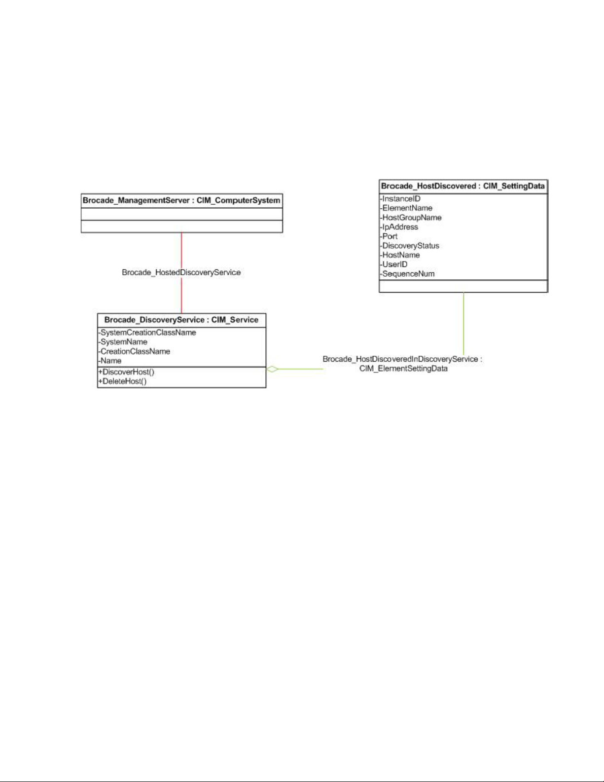
Data model
• The Brocade_Fabric has two new additional properties, SeedSwitchWWN and SeedSwitchIP.
• The connection setting of each switch is associated to the discovery service.
• Every switch in the discovered fabric is represented with an instance of
Brocade_SwitchConnectionSettings. This instance gives the data to be provided in the discover
Fabric dialog box of the Brocade Network Advisor client, such as switch status, user ID, and so
on.
• The discovery service is hosted on the management server.
Figure 1 shows the data model of the fabric discovery through the SMIA extrinsic method.
Brocade Network Advisor SMI Agent Developer’s Guide 3
53-1003159-01
Page 20

Discovering a fabric and a host
1
FIGURE 1 Fabric discovery data model
Host discovery using SMIA extrinsic method
The CIMOM host discovery process enables the user to discover and delete hosts through an
extrinsic method implemented in the Brocade_DiscoveryService.
Features supported
The following features are supported by the CIMOM host discovery process:
• Option to discover all types of hosts supported by Brocade Network Advisor.
• Option to delete a host based on the HostDiscovered COP provided.
• Option to receive the status of the host discovery information maintained in the
Brocade_HostDiscovered class.
• Option to receive the status of discovery or deletion requests on execution of the DiscoverHost
and DeleteHost methods.
Limitations
The following are the limitations of the CIMOM host discovery process:
• Supports only direct discovering of the host either through its IP address or its name, but does
not support for discovery from fabric or Virtual Machine (VM) Manager.
• Editing the host discovery information through the CIMOM is not supported.
• The history of the deleted host is not maintained in the CIMOM.
4 Brocade Network Advisor SMI Agent Developer’s Guide
53-1003159-01
Page 21
Discovering a fabric and a host
1
Data model
• The Brocade_HostDiscovered class gives the discovery information of each host associated to
the Discovery service.
• The discovery service is hosted on the management server.
Figure 2 shows the data model of the host discovery through the SMIA extrinsic method.
FIGURE 2 Host discovery data model
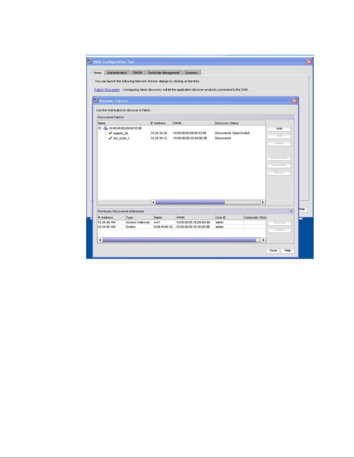
Discovery using SMIA Configuration Tool
The fabric and host can be discovered, edited, and deleted using the SMIA Configuration Tool. The
Home tab includes the Fabric Discovery and Host Discovery links to discover the fabric and host
respectively.
Figure 3 shows the fabric discovery through the SMIA Configuration Tool.
Brocade Network Advisor SMI Agent Developer’s Guide 5
53-1003159-01
Page 22
Discovering a fabric and a host
1
FIGURE 3 Fabric discovery using SMIA Configuration Tool
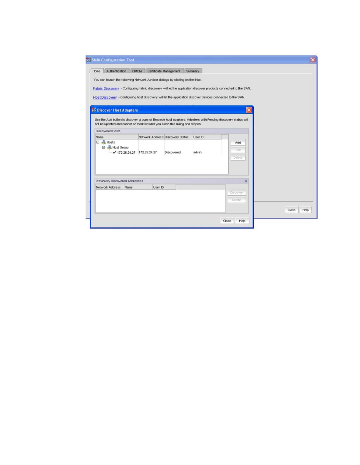
Figure 4 shows the host discovery through the SMIA Configuration Tool.
6 Brocade Network Advisor SMI Agent Developer’s Guide
53-1003159-01
Page 23
Discovering a fabric and a host
F
1
FIGURE 4 Host discovery using SMIA Configuration Tool
For more information related to fabric and host discovery, refer to the Brocade Network Advisor
User Manual.
Brocade Network Advisor SMI Agent Developer’s Guide 7
53-1003159-01
Page 24

Discovering a fabric and a host
1
8 Brocade Network Advisor SMI Agent Developer’s Guide
53-1003159-01
Page 25

Chapter
Managed Object Format Files
In this chapter
•Brocade Managed Object Format files. . . . . . . . . . . . . . . . . . . . . . . . . . . . . . . 9
•Additional MOF description specifications. . . . . . . . . . . . . . . . . . . . . . . . . . . 10
Brocade Managed Object Format files
Brocade supplies Managed Object Format (MOF) files for managing Brocade objects.
The following top-level files load MOF files into specific namespaces:
• BrocadeNamespace.mof links MOF files loaded in the root/brocade1 namespace.
• InteropNamespace.mof links MOF files loaded in the interop namespace.
Tab le 1 lists the files that contain Brocade MOF definitions.
TABLE 1 Brocade Managed Object Format files
MOF filename Description
2
BrocadeAccessGateway.mof Access Gateway
BrocadeAccessPoint.mof Access Point subprofile
BrocadeAgent.mof CIMOM Agent
BrocadeAGStatistics.mof AGFCPort statistics
BrocadeBlade.mof Blade subprofile
BrocadeCEEACL.mof CEE ACL discovery and configuration
BrocadeCEEMap.mof CEE Map discovery and configuration
BrocadeEthernet.mof Ethernet switch discovery
BrocadeExtender.mof FCIP-capable switch modeling
BrocadeFabric.mof Fabric profile
BrocadeFabricDiscovery.mof Fabric Discovery
BrocadeFCHBA.mof FC HBA profile
BrocadeFCSwitch.mof FC Switch profile
BrocadeFDMI.mof FDMI subprofile
BrocadeFRU.mof Fan, Power Supply, Sensors profiles
BrocadeIndications.mof Indications
BrocadeJobControl.mof JobControl subprofile
BrocadeLAG.mof LAG discovery and configuration
Brocade Network Advisor SMI Agent Developer’s Guide 9
53-1003159-01
Page 26

Additional MOF description specifications
NOTE
2
TABLE 1 Brocade Managed Object Format files (Continued)
MOF filename Description
BrocadeLaunchInContext.mof Launch In Context profile
BrocadePartitioning.mof FabricVirtualFabrics subprofile
BrocadePhysicalPackage.mof Location subprofile
BrocadeProfile.mof Profile Registration
BrocadeSoftware.mof Software subprofile
BrocadeSwitchStatistics.mof SwitchFCPort statistics
BrocadeTopologyView.mof Topology view
BrocadeVLAN.mof VLAN discovery and configuration
BrocadeZoning.mof Zone Control and SAN zoning subprofile
The Brocade subclasses do not automatically override all of the properties in the superclass. The
properties that are not overridden have a null value unless the superclass has a default value that
is defined in the MOF.
When the property in the MOF is defined to be of type sint16, then the equivalent Java type is
java.lang.Short.
FCR subprofile
Physical Package subprofile
Additional MOF description specifications
The Brocade MOF files contain additional specification-related information in the Description
qualifier. The following situations are described:
• If a given instance of a class can be created or deleted by the Brocade Network Advisor SMI
Agent
• If a given class or property applies only to specific switch firmware versions
Creating and deleting instances
If instances of a class can be intrinsically created and deleted, the following line is included in the
Description qualifier:
Instances of this class can be created and deleted by a client
If instances of a class can only be created, the following line is included in the Description qualifier:
Instances of this class can be created by a client
If instances of a class can only be deleted, the following line is included in the Description qualifier:
Instances of this class can be deleted by a client
10 Brocade Network Advisor SMI Agent Developer’s Guide
53-1003159-01
Page 27

Additional MOF description specifications
For example:
[Provider("java:com.brocade.api.cim.provider.zoning.Brocade_ZoneSetProvider"),
Description (
"Brocade_ZoneSet is a container of zones.\n\n"
"Instances of this class can be deleted by a client.")]
class Brocade_ZoneSet: CIM_ZoneSet {
2
Deprecation qualifier
Instance classes, association classes, properties, or extrinsic methods that have the Common
Information Model (CIM) qualifier deprecated in the MOF definition will continue to be implemented
in the Brocade Network Advisor SMI Agent. If a new implementation is documented, you should use
the new implementation as soon as possible to minimize backward-compatibility issues.
Brocade Network Advisor SMI Agent Developer’s Guide 11
53-1003159-01
Page 28

Additional MOF description specifications
2
12 Brocade Network Advisor SMI Agent Developer’s Guide
53-1003159-01
Page 29
Chapter
Profiles and Subprofiles
In this chapter
•UML diagram conventions . . . . . . . . . . . . . . . . . . . . . . . . . . . . . . . . . . . . . . . 13
•SMI profiles and subprofiles. . . . . . . . . . . . . . . . . . . . . . . . . . . . . . . . . . . . . . 14
•Server profile . . . . . . . . . . . . . . . . . . . . . . . . . . . . . . . . . . . . . . . . . . . . . . . . . . 15
•Fabric profile . . . . . . . . . . . . . . . . . . . . . . . . . . . . . . . . . . . . . . . . . . . . . . . . . . 17
•Switch profile . . . . . . . . . . . . . . . . . . . . . . . . . . . . . . . . . . . . . . . . . . . . . . . . . . 43
•CP blades (Brocade extension). . . . . . . . . . . . . . . . . . . . . . . . . . . . . . . . . . . . 48
•FC HBA profile . . . . . . . . . . . . . . . . . . . . . . . . . . . . . . . . . . . . . . . . . . . . . . . . . 50
•Launch In Context profile . . . . . . . . . . . . . . . . . . . . . . . . . . . . . . . . . . . . . . . . 52
•CEE switch support . . . . . . . . . . . . . . . . . . . . . . . . . . . . . . . . . . . . . . . . . . . . . 56
•Fabric switch partitioning subprofile . . . . . . . . . . . . . . . . . . . . . . . . . . . . . . . 77
•FC routing. . . . . . . . . . . . . . . . . . . . . . . . . . . . . . . . . . . . . . . . . . . . . . . . . . . . . 78
•Brocade Access Gateway and NPIV . . . . . . . . . . . . . . . . . . . . . . . . . . . . . . . . 89
•FRU profiles . . . . . . . . . . . . . . . . . . . . . . . . . . . . . . . . . . . . . . . . . . . . . . . . . . 101
•Names . . . . . . . . . . . . . . . . . . . . . . . . . . . . . . . . . . . . . . . . . . . . . . . . . . . . . . 103
3
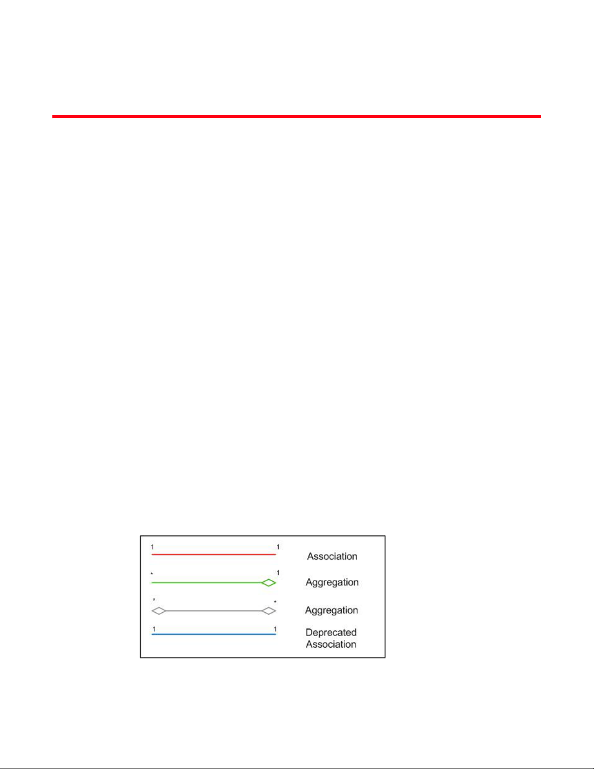
UML diagram conventions
This chapter provides Unified Modeling Language (UML) diagrams depicting the Brocade additions
to the Brocade Network Advisor SMI Agent. Each UML diagram corresponds to the Brocade
Managed Object Format (MOF) file of the same name.
Figure 5 illustrates the conventions used in the UML diagrams.
FIGURE 5 UML diagram convention
Brocade Network Advisor SMI Agent Developer’s Guide 13
53-1003159-01
Page 30

SMI profiles and subprofiles
3
SMI profiles and subprofiles
Tab le 2 lists the features supported by the Brocade Network Advisor SMI Agent. All SMI-S profiles
and subprofiles conforms to SMI-S 1.4. Other profiles and subprofiles are vendor extensions.
TABLE 2 SMI profiles and subprofiles
Profile Subprofile SMI-S version
Server Indications 1.4
Profile Registration 1.0.0
Object Manager Adapter 1.4
Fabric Fabric Profile 1.4
Zone Control 1.4
Enhanced Zoning and Enhanced Zoning Control 1.4
FDMI 1.2
FabricVirtualFabrics 1.2
FabricView 1.5
Switch Switch Profile 1.3
Blades 1.4
Physical Package 1.3
Software 1.4
Access Points 1.3
Location 1.4
FabricSwitchPartitioning 1.2
Host FC HBA Profile 1.3
FC Initiator Ports Subprofile 1.3
Fan, Power Supply, and
Sensor
Security Role-Based Authorization (CEE ACL only) 1.0.0
FC Router Inter-Fabric Routing Profile 1.5
Launch In Context Launch In Context Profile 1.5
Access Gateway (AG) and
Node Port Initialized
Virtualization (NPIV)
Fan Profile 1.0.0
Sensors Profile 1.0.0
Power Supply Profile 1.0.0
N_Port Virtualizer Profile 1.5
Physical Package 1.5
14 Brocade Network Advisor SMI Agent Developer’s Guide
53-1003159-01
Page 31

Other features supported by
NOTE
Brocade Network Advisor SMI Agent
The following are the additional features supported by Brocade Network Advisor SMI Agent:
• Support for Fibre Channel Router (FCR), modeled through the FabricSwitchPartitioning
• Names
• Support for the Converged Enhanced Ethernet (CEE) switch
• Support for Zoning Session operations through Job Control
• Support for selected indications
• SAN zoning
• Support for fabric discovery and host discovery
Server profile
The Server profile is supported by the Web-Based Enterprise Management (WBEM) Solutions J
WBEM Server CIMOM. The Brocade Network Advisor SMI Agent is a combination of two products,
the CIMOM and the provider product. Each product supports its software as shown in Figure 6.
subprofile
Server profile
3
The Brocade Network Advisor SMI Agent's J WBEM Server has been upgraded from version 3.4.3 to
version 3.9.0. The 64 bit Network Advisor will contain a 64 bit JServer with it and the 32 bit Network
Advisor will contain a 32 bit JServer.
Brocade Network Advisor SMI Agent Developer’s Guide 15
53-1003159-01
Page 32

3
Server profile
FIGURE 6 Server profile
Indications subprofile
The Indications subprofile is supported by the WBEM Solutions J WBEM Server CIMOM as shown in
Figure 7.
16 Brocade Network Advisor SMI Agent Developer’s Guide
53-1003159-01
Page 33

Fabric profile
FIGURE 7 Indications profile
Object manager adapter subprofile
The object manager adapter subprofile is supported by the WBEM Solutions J WBEM Server
CIMOM.
3
Fabric profile
The Brocade Network Advisor SMI Agent supports the Storage Networking Industry Association
(SNIA) Fabric profile, which defines the model and functions of a storage network for topology and
zoning control.
• A Brocade_SAN (CIM_AdminDomain) instance represents a SAN containing one or more
• A Brocade_SAN instance in CIM is keyed by the property name with an associated optional
• A fabric or SAN instance both inheriting CIM_AdminDomain are differentiated using the
From a SMI perspective, all fabrics which are physically connected are considered to be contained
in the same SAN.
Brocade_Fabric (CIM_AdminDomain) instances that are physically interconnected. A SAN and
a fabric are considered to be a group of components that operate together as a single system
and should be managed as such. The containment of Brocade_Fabric instances to
Brocade_SAN instances is through the associated Brocade_FabricInSAN
(CIM_ContainedDomain).
property, NameFormat. Name is opaque and NameFormat identifies how the property name is
generated. In the case of Brocade_SAN, the property NameFormat is set to WWN. Simple
fabric - Brocade_SAN.Name is the principal WWN of the fabric.
OtherIdentifyingInfo property.
• For Brocade_SAN, OtherIdentifyingInfo = SAN
• For Brocade_Fabric, OtherIdentifyingInfo = FABRIC
• For both Brocade_SAN and Brocade_Fabric, IdentifyingDescriptions = SNIA:DetailedType
Rules governing Brocade_SAN.Name
The following are the rules that govern the naming of SANs:
• In virtual fabrics with dedicated ISL between the base switches where all virtual fabrics have
been discovered, Brocade_SAN.Name is the principal WWN of the base fabric.
Brocade Network Advisor SMI Agent Developer’s Guide 17
53-1003159-01
Page 34

3
Fabric profile
• In virtual fabrics with dedicated ISL between the base switches where some of virtual fabrics
have been discovered but there is no base fabric.
- If the base fabric is discovered, Brocade_SAN.Name is the principal WWN of the base
fabric.
- If the base fabric is not discovered, the virtual fabrics will be disjointed and in each fabric
one SAN instance will be generated.
• In Virtual fabrics with no dedicated ISL between the base switches but with a dedicated ISL
between one of the discovered virtual fabrics.
- In the absence of a dedicated ISL between the base switches, no actual logical fabrics
exist except for those which have a dedicated ISL. The virtual fabrics will be disjointed and
in each fabric one SAN instance will be generated.
• A FCR setup where the backbone fabric and edge fabrics have been discovered,
Brocade_SAN.Name is the principal WWN of the backbone fabric.
• A FCR setup where only one or more edge fabrics have been discovered.
- In the absence of the backbone, each edge fabric is associated to its own SAN instance
and the Brocade_SAN.Name is the principal WWN of that edge fabric.
• When a single edge fabric is connected to more than one separate backbone fabric, all the
fabrics will be discovered as a single SAN. The Brocade_SAN.Name is the principal WWN of
one of the backbone fabric.
• A fabric containing a CEE switch, Brocade_SAN.Name is the principal WWN of the Fibre
Channel fabric with the switch.
• In a simple Fibre Channel fabric, Brocade_SAN.Name is the principal WWN of the fabric.
Registration
Figure 8 shows the SNIA profile registration profile model to advertise the Fabric profile and its
subprofiles.
18 Brocade Network Advisor SMI Agent Developer’s Guide
53-1003159-01
Page 35

Fabric profile
3
FIGURE 8 Fabric profile registration
Data model
Figure 9 shows the Fabric profile data model with the classes and properties that are supported to
conform to the Fabric profile. Only those properties that are mandatory are considered.
Brocade Network Advisor SMI Agent Developer’s Guide 19
53-1003159-01
Page 36

3
Fabric profile
FIGURE 9 Fabric profile
20 Brocade Network Advisor SMI Agent Developer’s Guide
53-1003159-01
Page 37

Fabric profile
NOTE
NOTE
NOTE
The following properties are mapped with the value specified to differentiate between
Brocade_Fabric and Brocade_SAN instances.
Brocade_Fabric instance:
OtherIdentifyingInfo[] = {"Fabric"}
IdentifyingDescriptions[] = {"SNIA:DetailedType"}
Brocade_SAN instance:
OtherIdentifyingInfo[] = {"SAN"}
IdentifyingDescriptions[] = {"SNIA:DetailedType"}
The SwitchId property will be populated only for switches running FOS 7.1.0 onwards.
3
Brocade_SAN.ElementName properties
The following are the properties of Brocade_SAN.ElementName:
• Brocade_SAN.ElementName is a descriptive name to identify the SAN.
• The default value for ElementName is the Brocade_SAN.Name property value.
• Supports the set operation that is used to set the user-friendly name to SAN. The name can be
up to 15 characters.
• The Brocade_SAN.ElementName will not get reset unless all the fabrics in the SAN have been
deleted from Brocade Network Advisor.
• If the principal switch of the fabric changes then the associated SAN name for the SAN will be
retained.
• For SAN consisting of multiple fabrics SAN name would be retained until all the fabrics in the
SAN get deleted.
• For multiple fabrics managed by BNA merge, the name of the SAN whose SAN key is retained
becomes the new SAN ElementName.
• For SAN that splits into multiple fabrics, the SAN which has the same name as the original SAN
would retain its name.
The default value for Brocade_SAN.ElementName is the Brocade_SAN.Name property value.
For more information about Brocade_SAN.ElementName default values, refer to “Rules governing
Brocade_SAN.Name” on page 17.
Limitations
The following are the limitations of the Brocade_SAN.ElementName:
• The ElementName is changed whenever the SAN WWN is changed.
• The SAN user-friendly name is deleted when the fabric is deleted. For example, assume a
fabric with switch1 as principal switch and you configure a SAN Element Name.
- If the firmware is upgraded in the switch1 and it goes down momentarily, then switch2
becomes the principal switch in that fabric and the Element Name is changed to default.
- When the switch1 comes active and becomes the principal switch, then the configured
SAN ElementName is reset to the configured name.
Brocade Network Advisor SMI Agent Developer’s Guide 21
53-1003159-01
Page 38

3
Fabric profile
• The SAN element name is reset to the default value when the principal switch WWN is changed
during fabric merge or segmentation.
- For example, assume there are two switch fabrics where switch1 is the seed switch and
switch2 is the principal switch, and SAN Element name is configured. If a switch3 joins the
fabric as a principal switch, then the element name changes to switch3 WWN and the
configured name is lost.
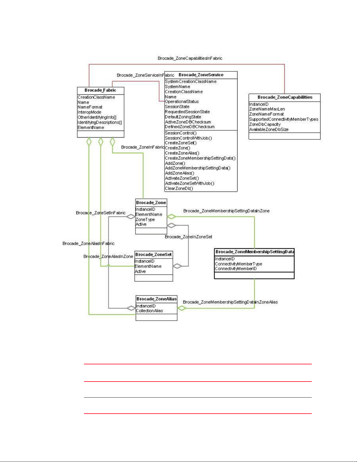
Zone control and enhanced zone control subprofiles
The zone control subprofiles enable discovery of a fabric's zone database and provisioning of
zoning operations.
Registration
Refer to “Registration” on page 18.
Data model
Figure 10 shows the data model with the classes and properties that are supported to conform to
these subprofiles. Only those properties that are mandatory are considered.
22 Brocade Network Advisor SMI Agent Developer’s Guide
53-1003159-01
Page 39
Fabric profile
3
FIGURE 10 Zone control and enhanced zone control subprofiles data model
Tab le 3 outlines the required CIM elements for the zone control subprofile.
TABLE 3 CIM elements for zone control subprofile
ElementName Description Currently
supported Y/N?
CIM_HostedService Associates the ZoneService to the Admin Domain
representing the fabric.
CIM_ZoneService The service that allows for all of the zoning
configuration changes.
Brocade Network Advisor SMI Agent Developer’s Guide 23
53-1003159-01
Yes
Yes
Page 40

3
Fabric profile
Extrinsic methods
The Brocade_ZoneService class contains the following extrinsic methods of the zone control
subprofiles:
• CreateZoneSet
• CreateZone
• CreateZoneAlias
• CreateZoneMembershipSettingData
• AddZone
• AddZoneAlias
• AddZoneMembershipSettingData
• ActivateZoneSet
• SessionControl
• ActivateZoneSetWithJob
• SessionControlWithJob
The following method is Brocade extension:
• ClearZoneDB
Zoning operation behavior
The Brocade Network Advisor SMI Agent depends on Brocade Network Advisor to support zoning.
The Brocade Network Advisor SMI Agent supports pure Fabric Operating System (FOS), mixed
fabrics, as well as pure Enterprise Operating System (EOS) fabrics.
The following are the zoning operation behaviors:
• All the operations as shown in Figure 10 are supported.
• Starting a zoning transaction is done by invoking the SessionControl method. Only one CIM
client is allowed to do zoning on a particular fabric at a time from the same Brocade Network
Advisor SMI Agent. However, with the Brocade Network Advisor SMI Agent, the transaction lock
is only local and it is not open on the switch. The operation returns Success without actually
doing anything on the switch. The same applies to the abort operation.
• Even though SMI zoning operations appear atomic in nature, the changes are delivered to the
fabric as a whole. The changes made by a CIM client are not visible to any other client, not even
on Telnet until the transaction is committed successfully.
• The operations Activate (including with job), Deactivate (including with job), and ClearZoneDB
are supported only outside the scope of a zoning transaction. If a transaction is open, then the
changes must be done before activating, deactivating, or clearing the database.
• A user is identified by Brocade Network Advisor user name only, and so a zoning transaction
opened by user1 on host1 can be used by the same user1 on some other host if it is still open.
The IP address of the host does not configure as part of the user name.
• A commit operation is successful once the zoning changes are accepted by the seed switch.
The successful completion of a commit operation does not mean that all the changes have
been propagated to the entire fabric.
24 Brocade Network Advisor SMI Agent Developer’s Guide
53-1003159-01
Page 41

Fabric profile
3
• If a Brocade Network Advisor client first starts zoning on a fabric (opens a zoning dialog box for
that fabric) and then an SMI client starts a transaction on the same fabric, a notification is sent
to the Brocade Network Advisor client that another user is starting zoning operations. This is a
broadcast notification to all the Brocade Network Advisor clients that currently have the zoning
dialog box open to do zoning configuration on the same fabric. This behavior is the same as
between two Brocade Network Advisor clients.
• If an SMI client starts a transaction on a fabric and a Brocade Network Advisor client opens a
zoning dialog box, a notification is issued, which need not be considered. The SMI client could
be in the middle of the session changes.
• If the SMI client commits first, the Brocade Network Advisor client is notified that the zone
database has been changed. The Brocade Network Advisor client has the option of ignoring or
refreshing the zone database copy. This is a warning message and there is nothing preventing
the Brocade Network Advisor client from ignoring the warning. This behavior is the same as
between two Brocade Network Advisor clients.
• If a Brocade Network Advisor client commits the changes first, the SMI client's zone
transaction is aborted and an indication is sent.
• If the time for which an open transaction is idle or greater than Brocade_ZoneService.Timeout
(value in seconds), the SMI client's zone transaction is aborted and an indication is sent.
• Error code 32770 is mapped to Transaction_Not_Started, which is different from the host
agent where it is No_Transaction.
• Error code 32772 is mapped to Transaction_Already_Started, which is different from the host
agent where it is Tra nsact ion_ Alrea dy_On .
• Error code 32781 is a new error code mapping to Transaction_Not_Available. This will be
returned to a CIMClient on SessionControl in the event that the zoning transaction on that
fabric is already opened by some other CIMClient.
• Error code 32775 mapped to Too Many Members no longer exists.
• Indication is not delivered when the client intentionally aborts a transaction.
• The fabric assist zoning feature is not supported and therefore the H{<WWN>} notation for a
fabric member is not supported in the SMI Agent.
Job control profile for SessionControlWithJob and ActivateZoneSetWithJob
During a commit or activate operation, it is possible that the operation takes time to complete.
Internally, the ZoningServer posts the operation to the switch through Hypertext Transfer Protocol
(HTTP), which then keeps polling the result until it receives a success or failure. The time lag
between the post and poll result depends on the zone database size on a Fabric OS.
To prevent blocking of the CIMClient, two asynchronous methods have been provided in the
Brocade_ZoneService, namely SessionControlWithJob and ActivateZoneSetWithJob. The execution
of these methods returns a Brocade_ConcreteJob instance when the CIM client commit SAN Zone
changes through SANSessionControl extrinsic call. The Brocade_ConcreteJob and
Brocade_SANZoneService are associated by Brocade_SANZoneControlOwningJobElement and
Brocade_SANZoneControlAffectedElement classes.
Even though this subprofile is used, the Brocade Network Advisor SMI Agent will not be 100
percent compliant. For example, the extrinsic method GetError() is not supported. Therefore, this
subprofile is not advertised.
Brocade Network Advisor SMI Agent Developer’s Guide 25
53-1003159-01
Page 42

3
Fabric profile
Data model
Figure 11 shows the classes and properties of the Job control subprofile.
FIGURE 11 Job control subprofile for zoning
Zoning behavior details
• Only SessionControlWithJob on a commit operation returns a Brocade_ConcreteJob instance.
Start and abort operations are not asynchronous.
• For SessionControlWithJob and ActivateZoneSetWithJob, the affected ManagedElement is the
Brocade_ZoneService whose SessionState and checksums are affected.
• Once a job is started and is in progress, its PercentComplete property always indicate 50
percent till job complete, at which time it will indicate 100 percent.
• The DeleteOnCompletion property is always set to false, indicating that all jobs, failed or
completed must be deleted explicitly by the CIMClient using the deleteInstance intrinsic
method. Otherwise, they will continue to exist in the Completed state.
• Because there is no automatic deletion of completed jobs by the Brocade Network Advisor SMI
Agent, the TimeBeforeRemoval property is not applicable and is always set to zero.
• If a completed job is not deleted and a new job for the same operation on the same target is
started, the new job replaces the old job. The old job is permanently deleted.
26 Brocade Network Advisor SMI Agent Developer’s Guide
53-1003159-01
Page 43

Fabric profile
3
• A second job for the same operation and same target cannot be started if a job is already in
progress and in the running state.
• A failed job shows an OperationalStatus of {"6", "17"}, while a successful job shows {"2", "17"}.
• Although the GetError() method is mandatory, this operation is not supported.
• Upon Brocade Network Advisor server restart, all existing Brocade_ConcreteJob instances are
deleted because they are not persisted in the Brocade Network Advisor database.
Supported indications
Tab le 4 shows all the supported mandatory indications.
TABLE 4 Supported indications
Indication Description
SELECT * FROM CIM_InstModification WHERE
SourceInstance ISA CIM_ConcreteJob AND
SourceInstance.CIM_ConcreteJob::PercentComplet
e <> PreviousInstance.CIM_ConcreteJob::Percent
Complete
SELECT * FROM CIM_InstModification WHERE
SourceInstance ISA CIM_ConcreteJob AND ANY
SourceInstance.CIM_ConcreteJob::Operation
alStatus[*] = 17 AND ANY
SourceInstance.CIM_ConcreteJob::Operation
alStatus[*] = 2
SELECT * FROM CIM_InstModification WHERE
SourceInstance ISA CIM_ConcreteJob AND ANY
SourceInstance.CIM_ConcreteJob::Operation
alStatus[*] = 17 AND ANY
SourceInstance.CIM_ConcreteJob::Operation
alStatus[*] = 6
SELECT * FROM CIM_InstModification WHERE
SourceInstance ISA CIM_ConcreteJob AND
SourceInstance.CIM_ConcreteJob::JobState <>
PreviousInstance.CIM_ConcreteJob::JobState
SELECT * FROM CIM_InstCreation WHERE
SourceInstance ISA CIM_ConcreteJob
SAN zoning
Modification of PercentComplete for a concrete job.
Modification of OperationalStatus for a
concrete job to Complete and OK.
Modification of OperationalStatus for a
concrete job to Complete and Error.
Modification of JobState for a concrete job.
Creation of a concrete job.
Storage Area Network (SAN) zoning is a method of arranging Fibre Channel devices into logical
groups over the physical configuration of the fabric. Brocade Network Advisor SMI Agent provides
SAN zoning configuration support such as CreateSANZone, AddSANZoneMemembers,
RemoveSANZoneMembers, and DeleteSANZone through extrinsic methods.
A Logical Storage Area Network (LSAN) consist of zones in two or more edge fabrics or backbone
fabrics that contain the same devices.The LSANs provide selective device connectivity between
fabrics without forcing you to merge those fabrics.
Brocade Network Advisor SMI Agent Developer’s Guide 27
53-1003159-01
Page 44

3
Fabric profile
LSAN zoning configuration guidelines
The following are the guidelines for configuring LSAN zones:
• The LSAN zone name starts with the prefix “LSAN_”.
• The LSAN zone name is case-sensitive.
• The members must be identified by their port WWN because the port IDs are not unique across
fabrics.
• The names and membership of the same LSAN zone in various fabrics need to be the same
while the order of membership is not necessary.
LSAN zoning in Brocade Network Advisor
The following are the behaviors of Brocade Network Advisor client for LSAN zoning:
• The LSAN zoning device sharing operations are done only through backbone fabrics. This
option is disabled for other edge fabrics.
• The LSAN zone can be added to any managed edge fabrics and backbones during the zone
activation.
• The SMI Agent behavior is same as the client.
Registration
There is no profile registration for this model.
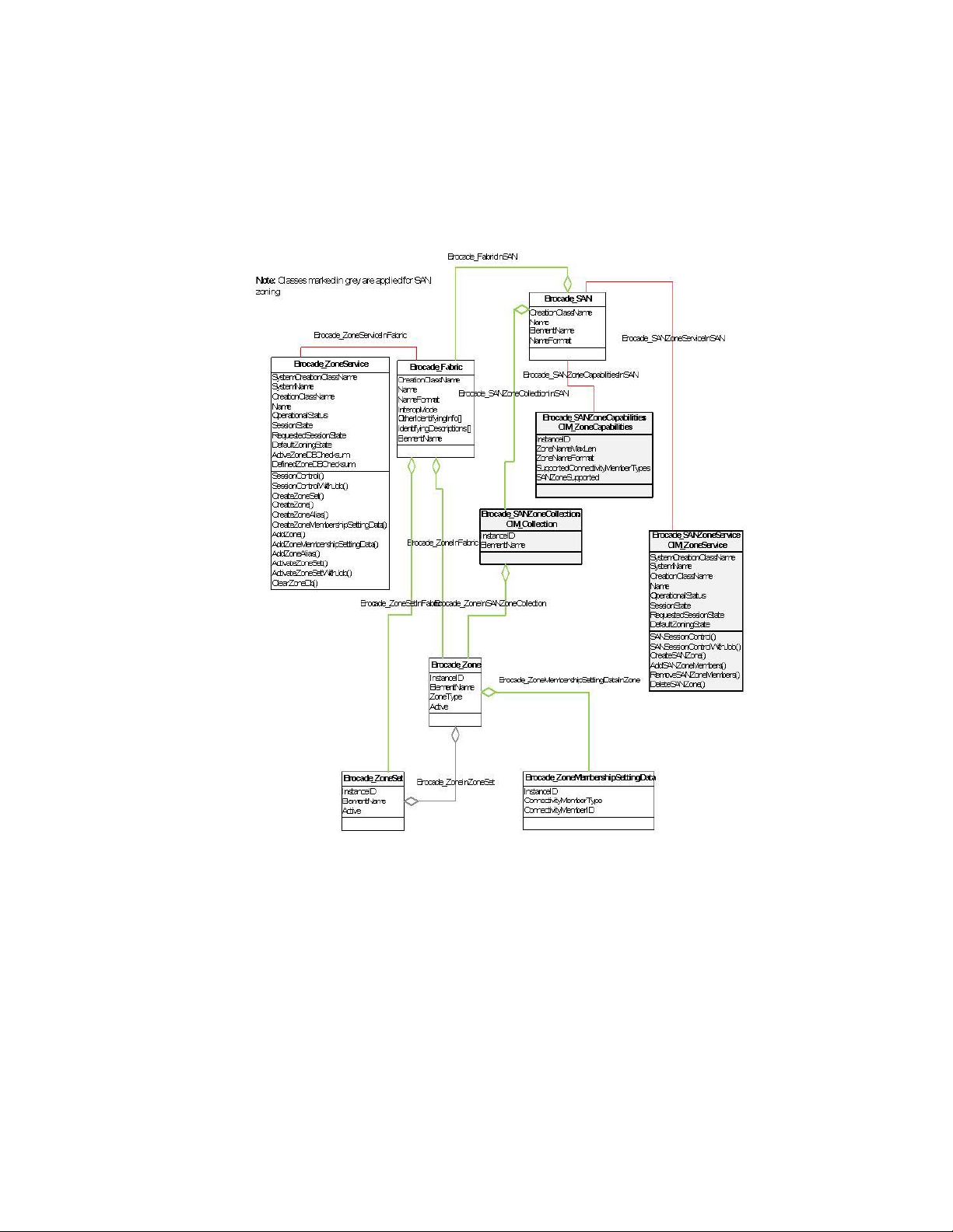
Data model
Figure 12 shows the data model of SAN zoning.
28 Brocade Network Advisor SMI Agent Developer’s Guide
53-1003159-01
Page 45
Fabric profile
3
FIGURE 12 SAN zoning data model
SAN zoning operation behavior
The following are the operation behaviors of SAN zoning:
• SAN zoning is available only for SAN with backbone fabrics.
• Brocade_SANZoneService, Brocade_SANZoneCapabilities, and Brocade_SANZoneCollection
are associated to Brocade_SAN.
• The Brocade_SANZoneCapabilities supports only the mandatory properties such as
InstanceID, ZoneNameMaxLen, ZoneNameFormat, and SupportedConnectivityMemberTypes.
Brocade Network Advisor SMI Agent Developer’s Guide 29
53-1003159-01
Page 46

3
Fabric profile
• The SANZoneSupported property is added in the Brocade_SANZoneCapabilities to indicate the
SAN zone support.
• The Brocade_SANZoneService supports the following extrinsic methods:
- SANSessionControl
- SANSessionControlWithJob
- CreateSANZone
- AddSANZoneMembers
- RemoveSANZoneMembers
- DeleteSANZone
• The CIM_ZoneService such as CreateZoneSet, CreateZone, and CreateZoneAlias are not
supported in Brocade_SANZoneService.
• Use SANSessionControl method with RequestedSessionState=2 to start a session before
configuring SAN zones through CreateSANZone, AddSANZoneMembers,
RemoveSANZoneMembers, and DeleteSANZone extrinsic methods.
• The SAN zones are activated while the session is closed using SANSessionControl method with
RequestedSessionState=3.
• You cannot open a session for SAN level zoning and Fabric level zoning simultaneously for a
particular backbone fabric. If you start with a session for SAN level zone, it must be closed
before starting the session for fabric level zone and vice versa.
• The CreateSANZone() in Brocade_SANZoneService will get the SAN zone name, list of member
WWNs, and SANZoneType as inputs. A zone with multiple members is created and activated in
the backbone or edge fabrics based on the members.
• The AddSANZoneMembers() in Brocade_SANZoneService will get the SAN zone name and
member WWNs as input. Add the zone members to LSAN zone and reactivate the LSAN zone.
• The RemoveSANZoneMembers() in Brocade_SANZoneService will get the SAN zone name and
member WWNs as input. Remove those zone members from LSAN zone and reactivate the
LSAN zone.
• The DeleteSANZone() in Brocade_SANZoneService will get the zone name as input and deletes
the same zone from the fabrics.
• Only WWN zone member type is supported, and Domain:PortIndex zone member type is not
supported in SAN level zoning.
• CreateSANZone, AddSANZoneMembers, and RemoveSANZoneMembers calls return an error
code 5 (CIM_ERR_INVALID_PARAMETER), if the zone members are not WWN member type.
• The AddSANZoneMembers extrinsic call will not return an error, when duplicate members are
already present in zone.
• The RemoveSANZoneMembers extrinsic call will not return errors, when the requested
member is not present in the zone.
• The Brocade_SANZoneCollection represents the SAN zones in SAN.
• The Brocade_ZoneInSANZoneCollection represents the association between
Brocade_SANZoneCollection (SAN Zone) and Brocade_Zone (active zones in backbone or edge
fabrics).
• The SAN zone is added under an existing active zone configurations during SAN zone
activation. If there is no active configuration in the edge fabric or backbone fabric, a zone set
with the name of “LSAN_CFG_<date/time>” is created and the respective SAN zone is added
under this zone set.
30 Brocade Network Advisor SMI Agent Developer’s Guide
53-1003159-01
Page 47
Fabric profile
NOTE
E
Host
Target 1
Target 3
Target 2
Fabric 1
Fabric 2
Fabric 4
Fabric 3
FC router 1
FC router 2
Backbone fabric
FC router 3 FC router 4
EX
EX
EX
EX
EX
EX
EX
EE
E
E
E
E
3
The name of SAN zone must start with “LSAN_”. Otherwise, the extrinsic call returns an error code:
5 (CIM_ERR_INVALID_PARAMETER). Invalid SANZone name: <SAN Zone name>.
Alert indication support
The following is the alert indication support for SAN zoning:
• Alert indication with message ID BRCD102 is delivered to CIM client, if there is a failure in SAN
zone activation through CIM client. It is not delivered if there is a failure in SAN zone activation
through Brocade Network Advisor client.
• Alert indication with message ID FC2 is delivered for successful activation because zoning
activation is performed at fabric level.
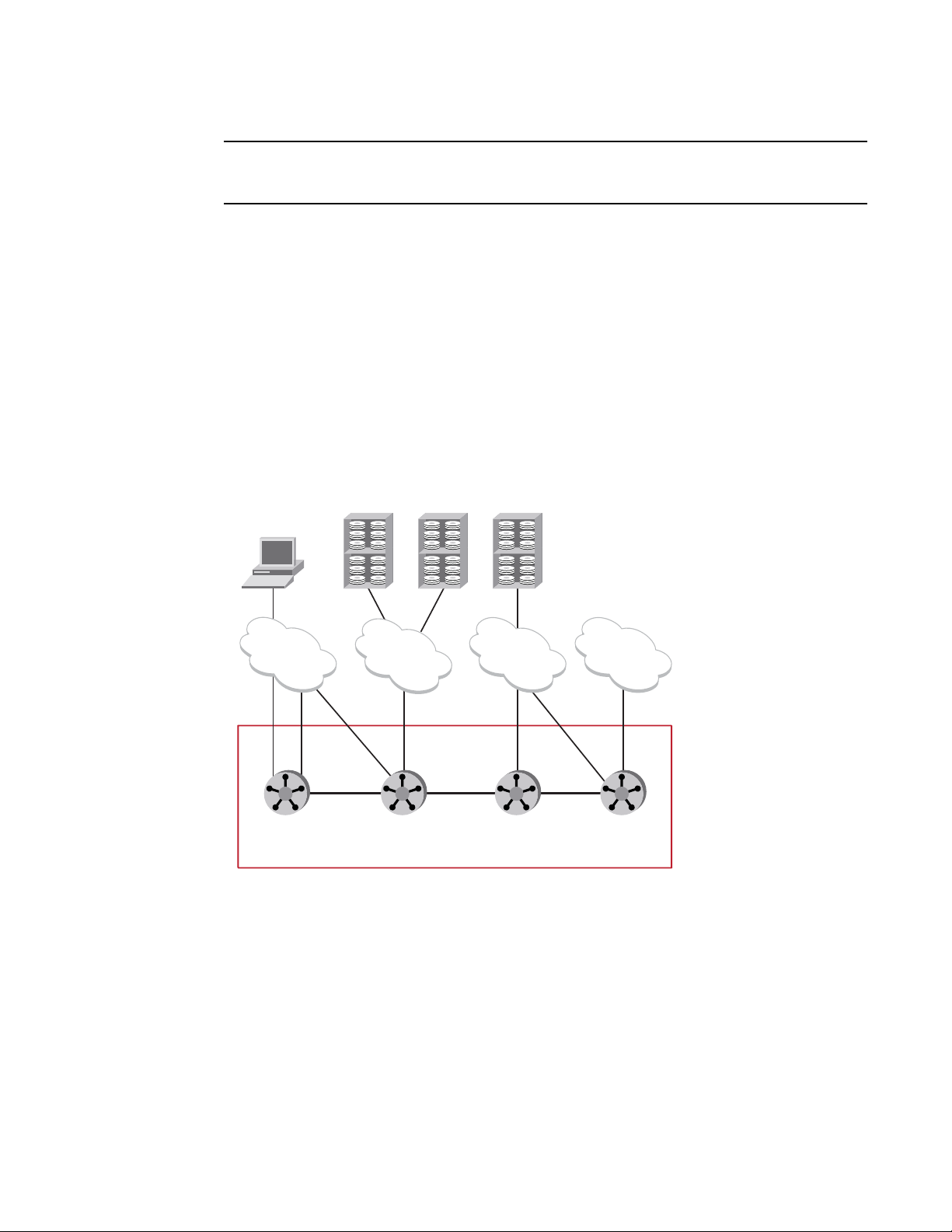
Use cases
Figure 13 explains a sample SAN configuration.
FIGURE 13 Sample SAN configuration
• Create a LSAN_Zone1, add WWN of Host, Target3 and activate the same zone. As the
LSAN_Zone1 has end devices from fabric1 and fabric3, it is activated to both the fabrics. The
following extrinsic calls are used for this operation:
- Activate the SAN zoning session with SANSessionControl (RequestedSessionState=2).
- Create an LSAN zone with CreateSANZone (SANZoneName=LSAN_Zone1,
SANZoneType=LSAN, ZoneMembers={“Host WWN”, “Target 3 WWN”}).
- Commit the SAN zoning session with SANSessionControl (RequestedSessionState=3).
Brocade Network Advisor SMI Agent Developer’s Guide 31
53-1003159-01
Page 48

3
Fabric profile
• Create a LSAN_Zone2, add WWN of Host, Target1, Target3, and activate the same zone. As the
LSAN_Zone2 has devices from fabric1, fabric2, and fabric3, the LSAN_Zone2 is activated to all
the three fabrics.
• Create LSAN_Zone3 with offline zone members. As the LSAN_Zone3 has only offline members,
the operation is failed with error code 4 (FAILED).
• Create LSAN_Zone4, add host, and offline members and activate the same zone. It is activated
in fabric1 as the host belongs to fabric1.
• Adding a zone member:
- Add member operation is invoked with the input: WWN Target1 on LSAN_Zone1.
- The member is added to the zone in the fabric1 and fabric3. A copy of the zone is added to
the active zoneset of the fabric2.
- The following are the extrinsic calls used for this operation:
Activate the SAN zoning session with SANSessionControl (RequestedSessionState=2).
Add zone members with AddSANZoneMembers (SANZoneName=LSAN_Zone1,
ZoneMembers={“Target 1 WWN”}).
Commit the SAN zoning session with SANSessionControl (RequestedSessionState=3).
• Removing a zone member:
- Remove member operation is invoked with the input: WWN Target1.
- The member is removed from the zone in fabric1 and fabric3 and the copy of zone is
removed from the fabric2.
- The following extrinsic calls are used for this operation:
Activate the SAN zoning session with SANSessionControl (RequestedSessionState=2).
Remove zone members with RemoveSANZoneMembers
(SANZoneName=LSAN_Zone1, ZoneMembers={“Target 1 WWN”}).
Commit the SAN zoning session with SANSessionControl (RequestedSessionState=3).
• Delete a zone with input of zone name (LSAN_Zone1). It will be removed from all the edge
fabrics and backbone fabric.
- The following extrinsic calls are used for this operation:
Activate the SAN zoning session with SANSessionControl (RequestedSessionState=2).
Delete a zone with DeleteSANZone (SANZoneName=LSAN_Zone1).
Commit the SAN zoning session with SANSessionControl (RequestedSessionState=3).
• Delete a zone with input of zone name (LSAN_Zone7), which is not present in any of the
fabrics. The following error code is returned
- 4 (Failed).<LSAN_Zone7>: SAN Zone name is not found in zone DB.
• Subscribe BRCD102 indications and create SAN zone with online members. An indication with
message ID BRCD102 is delivered for activation failures.
• Create SAN zone with the prefix “XSAN_”, add some zones member WWNs, and activate the
zone. As there are invalid zone names, the failure error code 5
(CIM_ERR_INVALID_PARAMETER) is returned.
• Add some Domain:PortIndex zone members in the SAN zone. Due to invalid zone members,
the error code 5 (CIM_ERR_INVALID_PARAMETER) is returned.
32 Brocade Network Advisor SMI Agent Developer’s Guide
53-1003159-01
Page 49

Fabric profile
3
Fabric virtual fabrics subprofile
The fabric virtual fabrics subprofile models the partitioning of a physical fabric into one or more
logical fabrics. The physical fabric consists of one or more switches that can be partitioned. The
switch in the physical fabric that can be partitioned is called the partitioning system. The resulting
virtual fabric will consist of one or more switches formed from the partitioning systems. The
resulting virtual switch in the virtual fabric is called the partitioned system. The virtual fabric
topology, along with its virtual switches, is modeled as per the Fabric profile. The underlying
physical fabric topology, along with its partitioning systems, is modeled by the fabric virtual fabrics
subprofile. By using the Fabric profile with the fabric virtual fabrics subprofile, a logically separated
physical fabric can be discovered.
Fabric virtual fabrics form a single physical fabric. This scenario encompasses the following cases:
• All virtual fabrics are discovered with dedicated ISLs between the base switches.
- Brocade_SAN.Name is the principal WWN of the base fabric where all virtual fabrics have
been discovered.
- In the absence of a dedicated ISL between the base switches, no actual logical fabrics
exist except for those that have a dedicated ISL. The virtual fabrics are disjointed.
• All virtual fabrics are discovered with no dedicated ISLs between the base switches but
dedicated ISLs between logical switches.
• Only some virtual fabrics are discovered exclusive of base fabric.
Registration
Each virtual fabric represented by an instance of Brocade_Fabric, is associated to an instance of
Brocade_RegisteredProfile(Fabric). By SMI definition, all virtual fabrics that are physically
interconnected belong to the same SAN. The Brocade_SAN instance containing the virtual fabrics
associates itself to an instance of Brocade_RegisteredSubprofile (FabricVirtualFabrics) only if the
base switch is discovered. Refer to “Registration” on page 18.
Data model
Figure 14 models the required classes. The classes relevant in the Fabric profile are also included:
• Each physical switch is represented by an instance of Brocade_PhysicalComputerSystem.
• Each physical port is represented by an instance of Brocade_PCSNetworkPort.
• Each virtual fabric is represented by an instance of Brocade_Fabric.
• Each virtual switch is represented by an instance of Brocade_Switch.
• Each port within a virtual switch is represented by an instance of Brocade_SwitchFCPort.
• All virtual fabrics associate to a single Brocade_SAN instance.
• All virtual switches carved out from a single switch associate to a single
Brocade_PhysicalComputerSystem instance.
• All Brocade_PhysicalComputerSystem instances associate to a single Brocade_SAN instance.
Brocade Network Advisor SMI Agent Developer’s Guide 33
53-1003159-01
Page 50

3
Fabric profile
FIGURE 14 Fabric virtual fabrics subprofile data model
Sample discovery configuration
Figure 15 shows a sample Virtual Fabrics configuration. In this configuration, there are five physical
chassis. Chassis 1, Chassis 2, and Chassis 3 are physical chassis that are enabled for Virtual
Fabrics and divided into logical switches. Switch A and Switch B are single-switch chassis and are
not enabled for Virtual Fabrics.
34 Brocade Network Advisor SMI Agent Developer’s Guide
53-1003159-01
Page 51

Fabric profile
3
FIGURE 15 Sample Virtual Fabrics configuration, connecting the SMI Agent to a single chassis
For this example, assume that the SMI Agent is connected to the Chassis 2 IP address. The SMI
Agent can discover the following:
• 1 SAN
• 3 fabrics (Fabric ID 1, Fabric ID 2, and Fabric ID 3)
• 4 physical chassis
- Chassis 1
- Chassis 2
- Chassis 3
- The chassis for Switch B
• 9 switches
- 2 logical switches in Chassis 1
- 3 logical switches in Chassis 2
- 3 logical switches in Chassis 3
- Switch B
Logical switch 18 in Chassis 3 and Switch A, which is connected to this logical switch, are not
discovered.
• The physical and logical ports corresponding to the discovered switches
Brocade Network Advisor SMI Agent Developer’s Guide 35
53-1003159-01
Page 52

3
Fabric profile
• 7 SANActiveConnections corresponding to the discovered switches
- 2 XISLs
- 1 ISL
- 4 LISLs
• Zone databases (size = 1 MB for each fabric) corresponding to the three fabrics.
• All of the classes corresponding to the three discovered fabrics as defined in the Fabric and
other profiles.
To discover the fabric formed by Switch A and logical switch 18 in Chassis 3, the provider must be
configured to connect to either Chassis 3 or Switch A, because the Fabric OS will not provide the
information for these switches if the SMI Agent is connected only to Chassis 2.
The devices connected to ports in a logical switch are discovered in the fabrics to which these
switch ports belong. For example, a device connected to a port belonging to a logical switch with
Fabric ID 1 is discovered only if you have access to Fabric ID 1. Device discovery follows the existing
model in the Fabric profile.
Blades subprofile support
The following model supports the blade subprofile in Virtual Fabrics setup as the blade subprofile
in Virtual Fabrics scenario on a director switch is not specified in SMI-S 1.4:
• There is one instance of Brocade_Blade for each physical blade in the director switch.
• For each Brocade_Blade, there can be multiple Brocade_PortModule instances, depending on
the number of existing logical switches and how the ports are allocated throughout the
chassis.
• The association Brocade_PortModuleRealizes cannot be one-to-one in a Virtual Fabrics
scenario, but one-to-many.
Figure 16 shows a basic instance diagram for a director switch containing two logical switches,
where both the logical switches contain a port from the blade in slot 1.
FIGURE 16 Director switch instance diagram
36 Brocade Network Advisor SMI Agent Developer’s Guide
53-1003159-01
Page 53

Fabric profile
3
Topology view
The Topology View class was introduced in SMI-S 1.3 to increase the performance and reduce the
number of traversals required to discover topology.
The Network Advisor SMI Agent cannot provide a complete topology and its related information
including instances of classes like Brocade_TopologyView, Brocade_SanActiveConnection if one of
the switches involved goes unreachable or unmanageable.
Objectives
The objective is to deliver a class that can be enumerated, gives better performance than
enumerating Brocade_SANActiveConnection(CIM_ActiveConnection), and traverse to each
endpoint to gather data about the link between switch ports or between N_Ports and switchports.
Performance considerations
Performance should be significantly better than the combined performance of enumeration of
Brocade_SANActiveConnection (CIM_ActiveConnection) and traversals to endpoint instances
through CIMClient.associators call.
Registration
Figure 17 shows the registration model of Topology view.
FIGURE 17 Topology view registration model
Brocade Network Advisor SMI Agent Developer’s Guide 37
53-1003159-01
Page 54

3
Fabric profile
Data model
Figure 18 shows the data model of Topology view.
FIGURE 18 Topology view data model
FDMI subprofile
The Fabric-Device Management Interface (FDMI) enables the management of devices such as Host
Bus Adapters (HBAs) through the fabric. This subprofile models the discovery of HBA type devices
without having the SMI Agent reside on the host containing the HBA. It shows how an HBA is hosted
on the system (host) along with the nodes contained in it and ports controlled by it. It allows HBAs
to expose product information such as firmware version, vendor, serial number, and so on. This
model supports all HBA configurations such as single-node single-port HBA, single-node dual-port
HBA, and dual-node dual-port HBA.
38 Brocade Network Advisor SMI Agent Developer’s Guide
53-1003159-01
Page 55

Fabric profile
NOTE
3
Prerequisites
Only the HBAs that register a FDMI host name in the Name Server (NS) on the switch or fabric
support the Brocade_Platform model. Currently, the EOS switches do not support FDMI. Therefore,
HBAs connected to EOS switches do not support the Brocade_Platform model, including the
instance classes and association classes.
The switch connected to an FDMI-enabled HBA runs on Fabric OS v7.0.0 or later. Also, the seed
switch runs on Fabric OS v7.0.0 or later to support this profile.
Registration
Refer to “Registration” on page 18.
Data model
Figure 19 shows the class diagram of the classes and properties supported in the FDMI subprofile.
The instances for the CIM classes Brocade_SoftwareIdentity, Brocade_HBAProduct,
Brocade_PhysicalHBA, and Brocade_PortController are available as part of the FDMI subprofile
provided the switches are running Fabric OS v7.0.0 or later.
For a single-node single-port HBA, there is a single Brocade_Node instance hosted on a
Brocade_Platform and a single Brocade_PortController representing the logical aspects of the
Brocade_PhysicalHBA controlling a single Brocade_NodeFCPort.
For a single-node dual-port HBA, there is a single Brocade_Node hosted on a Brocade_Platform
and a single Brocade_PortController representing the logical aspects of the Brocade_PhysicalHBA
controlling both Brocade_NodeFCPort instances.
For a dual-node dual-port HBA, there are two Brocade_Node instances hosted on the same
Brocade_Platform and a single Brocade_PortController representing the logical aspects of the
Brocade_PhysicalHBA controlling both Brocade_NodeFCPort instances.
Brocade Network Advisor SMI Agent Developer’s Guide 39
53-1003159-01
Page 56

3
Fabric profile
FIGURE 19 FDMI data model
40 Brocade Network Advisor SMI Agent Developer’s Guide
53-1003159-01
Page 57

Fabric profile
NOTE
3
Trunking
This section defines the model for the trunking feature in Brocade Network Advisor SMI Agent. The
trunking model is supported only for FOS switches.
The m-EOS switches open trunking feature is not supported in Brocade Network Advisor SMI Agent
and there will not be any modeling m-EOS open trunking.
Both ISL trunking and F_Port trunking are supported for FOS switches.
Data model
Figure 20 shows the trunking class diagram.
FIGURE 20 Trunking class diagram
Refer to the corresponding class diagrams and profiles for Brocade_Switch,
Brocade_SwitchFCPort, and Brocade_AGFCPort properties.
Brocade Network Advisor SMI Agent Developer’s Guide 41
53-1003159-01
Page 58

3
Fabric profile
Related API and classes
Tab le 5 represents the group of switch ports forming a trunk.
TABLE 5 Brocade_Trunk: CIM_RedundancySet
Property name Type Description
InstanceID [Key] string InstanceID opaquely and uniquely identifies an instance of this
class.
The format of this key is as follows.
SOURCESWITCHWWN=<value>;
SOURCESWITCHTYPE=<value>:
DESTINATIONWWN=<value>;
SOURCESWITCHPORTWWN=<value>;
DESTPORTWWN=<value>;
CLASSNAME=Brocade_Trunk;
DESTINATIONTYPE=<value>;
SOURCE_WWN is the master switch WWN of one end.
SOURCE_PORT_WWN is the master port WWN of the trunk
members in a trunk group.
DEST_WWN is the WWN of the other end, which is a switch in case
of an ISL trunk and AG in case of an trunk.
DEST_PORT_WWN is the port WWN of the other end.
SOURCE_TYPE is the type of the source (Switch=0, Device=1)
DEST_TYPE is the type of the other end (Switch=0, Device=1)
TypeOfSet[] uint16 TypeOfSet provides information on the type of redundancy.
ElementName string A user-friendly name for the object.
RedundancyStatus uint16 RedundancyStatus provides information on the state of the
RedundancySet.
LoadBalanceAlgorithm uint16 The current load balance algorithm.
OtherTypeOfSet[] string When the corresponding array entry in TypeOfSet[] is “Other”, this
entry provides a string describing the type of set.
OtherLoadBalanceAlgorithm String When LoadBalanceAlgorithm is “Other”, this property describes
the algorithm.
Tab le 6 explains the properties of Brocade_TrunkInSwitch: CIM_HostedCollection class.
TABLE 6 Brocade_TrunkInSwitch: CIM_HostedCollection
Property name Type Description
Antecedent Brocade_Switch REF Represents the switch objects that
has the trunk.
Dependent Brocade_Trunk REF Represents the trunk object.
Tab le 7 explains the properties of Brocade_SwitchFCPortInTrunk: CIM_MemberOfCollection class.
TABLE 7 Brocade_SwitchFCPortInTrunk: CIM_MemberOfCollection
Property name Type Description
Collection Brocade_Trunk REF Represents the trunk object.
Member Brocade_SwitchFCPort REF Represents the member of the
trunk.
42 Brocade Network Advisor SMI Agent Developer’s Guide
53-1003159-01
Page 59

Tab le 8 explains the properties of Brocade_AGFCPortInTrunk: CIM_ MemberOfCollection class.
TABLE 8 Brocade_AGFCPortInTrunk: CIM_ MemberOfCollection
Property name Type Description
Collection Brocade_Trunk REF Represents the trunk object.
Member Brocade_AGFCPort REF Represents the member of the
Switch profile
The Storage Networking Industry Association (SNIA) switch profile defines the model and functions
of a fibre channel switch including state, status, and control of the device and its connections.
Registration
The SNIA Profile Registration Profile model is followed to advertise Switch profile and its
subprofiles.
trunk.
Switch profile
3
Figure 21 shows the instance diagram with the objects and properties for Switch profile
registration. Only for blades, the actual blade instances that conform to the Blades subprofile will
be associated. For the other subprofiles, such as Software, Access Points, and so on, the
association to the actual instances are not supported.
FIGURE 21 Switch profile registration
Brocade Network Advisor SMI Agent Developer’s Guide 43
53-1003159-01
Page 60

3
NOTE
Switch profile
Data model
Figure 22 shows the Switch profile data model.
FIGURE 22 Switch profile data model
The value of the Dedicated property of Brocade_Switch is Switch (5) and FC Switch (37).
The set operation for the Brocade_SwitchFCPortSettings.RequestedType is supported from Fabric
OS v6.3 and later.
44 Brocade Network Advisor SMI Agent Developer’s Guide
53-1003159-01
Page 61

Switch profile
NOTE
3
Switch un-monitoring is not supported from SMI perspective and if the switch is un monitored, then
the SMI Agent would return stale information.
Differentiation between switches and domains
The following properties are used in CIM_CompterSystem to differentiate a simple switch, a switch
created through VF, a switch created through Inter-Fabric Routing Profile (IFR), differentiating Front
Domain from the Translate Domain, and the physical system that is partitioned.
IdentifyingDescriptions = {"DomainID", "SNIA:DetailedType"};
OtherIdentifyingInfo = {"1", "Front Domain"}; where "1" is DomainID and type is Front Domain.
OtherIdentifyingInfo has the value of DomainID and switch detailed type (Front Domain, Translate
Domain, Virtual Switch or None).
In case of VF setup, OtherIdentifyingInfo additionally has the values of the VF_ID, and
IdentifyingDescriptions properties additionally has the value SNIA:VF_ID as the detailed type.
PortDiscriminator in CIM_FCPort differentiates among ports that support IFR (FCR), internal and
external ports, Virtual Fabrics (VF), Fibre Channel over IP (FCIP) and Fibre Channel over Ethernet
(FCoE). This property is applicable for only logical ports. The possible values are given in Table 9.
TABLE 9 PortDiscriminator values
No Port PortDiscriminator value
1 FC ports on the FCIP Ethernet port FCIP
2 Virtual FCoE ports inside the Brocade 8000 internal + FCoE
3 Virtualized node ports in NPIV and Access Gateway NPIV
4 Front and xlate phantom FC ports (except the FF port from
the backbone)
5 Front phantom FC port from the backbone connected to the
edge switch
6 ICL ports Chassis
7 Dynamically created FC ports for logical connections in
virtual fabrics
8 All other FC ports (like physical ports) Not Applicable
9 CU ports of Blade Switches Internal
IFR virtual
IFR
VF
Physical package, access points, software, blades, and location subprofiles
The Physical Package, Access Points, Software, Blades, and Location subprofiles model the
product information of a switch, the URL to launch the element manager of a switch, the blades
within the chassis, and the details such as primary system owner name, contact, and location for a
Brocade_Chassis.
Tab le 10 explains the subprofiles and their functions.
Brocade Network Advisor SMI Agent Developer’s Guide 45
53-1003159-01
Page 62

3
Switch profile
TABLE 10 Switch subprofiles
Subprofiles Description
Physical Package Models information about a storage system's physical
package and optionally about internal sub packages.
Access Points Provides remote access points for management tools.
Software Provides information on the installed controller software.
Blades Models the physical aspect of a blade in a director switch.
Location Models the location of a SAN Element.
Registration
Refer to “Registration” on page 43.
Data model
Figure 23 shows the data model with the classes and properties that are supported to conform to
the switch subprofiles.
46 Brocade Network Advisor SMI Agent Developer’s Guide
53-1003159-01
Page 63

Switch profile
3
FIGURE 23 Physical Package, Access Points, Software, Blades, and Location subprofiles data model
Brocade Network Advisor SMI Agent Developer’s Guide 47
53-1003159-01
Page 64

CP blades (Brocade extension)
NOTE
3
he Brocade_Chassis.ElementName property is set correctly in the corresponding instance only if the
seed switch is running on a Fabric OS v6.3.x or higher and if the chassisName in the switches of the
fabric are set after the seed switch firmware has been upgraded.
CP blades (Brocade extension)
This section details the modelling of the Core Processor (CP) blade and its associated properties (IP
address, state, and so on) on the director class Brocade switches.
Data model
Figure 24 shows the instance diagram of the CP blades.
48 Brocade Network Advisor SMI Agent Developer’s Guide
53-1003159-01
Page 65

CP blades (Brocade extension)
3
FIGURE 24 CP blades instances diagram
• Brocade_CPModule instances representing CP blades are not associated to
Brocade_RegisteredSubProfile through Brocade_ElementConformsToSubProfile.
• Each Brocade_Blade instance representing the CP blade is logically realized as
Brocade_CPModule:CIMLogicalModule. A different class for this logical module is used instead
of PortModule. The PortModule contains NumPorts property, which is not applicable here. The
association between the Brocade_Blade and the Brocade_CPModule is Brocade_CPRealizes.
• The Brocade_CPModule.OperationalStatus property shows the status of the CP whether active,
standby, or failed.
Brocade Network Advisor SMI Agent Developer’s Guide 49
53-1003159-01
Page 66

FC HBA profile
3
• The Brocade_CPModule.ModuleNumber shows the slot number of the CP blade.
• The Brocade_CPModule is associated to the Brocade_PhysicalComputerSystem using
• Each Brocade_CPModule is associated to a Brocade_CPMgmtAccessPoint, which shows the IP
• Each Brocade_CPModule is associated to a Brocade_CPSoftwareIdentity instance, which
• The Brocade_CPModule instances is aggregated to the Brocade_PhysicalComputerSystem,
Supported classes and associations
The supported classes and associations are shown in Figure 24.
FC HBA profile
Brocade_CPInPCS:CIM_SystemDevice. This association shows the containment relationship on
the logical side.
address of the CP.
shows the firmware running on the CP.
which is the parent system.
The Fibre Channel Host Bus Adapter (FC HBA) profile is similar to the FDMI subprofile. As with
FDMI, this model also supports all HBA configurations such as single node-single port HBA,
single-node dual-port HBA, and dual-node dual-port HBA.
Prerequisites
Only the HBAs discovered in Brocade Network Advisor are exposed through the FC HBA profile.
Data model
Figure 25 shows the data model of the FC HBA profile.
50 Brocade Network Advisor SMI Agent Developer’s Guide
53-1003159-01
Page 67

FC HBA profile
3
FIGURE 25 FC HBA profile data model
Brocade Network Advisor SMI Agent Developer’s Guide 51
53-1003159-01
Page 68

Launch In Context profile
NOTE
3
The HBA is represented by the PortController class and the serial number is the key.
Launch In Context profile
Brocade Network Advisor supports a number of services for network management, such as
Configure Names, Historical Performance Report, Fabric Ports Report, and so on. These services
are published through the Launch In Context (LIC) profile.
LIC names
Tab le 11 shows the list of LIC names and their descriptions.
TABLE 11 Description of LIC names
LIC name Description
About Displays the product and version information.
CEE_CEE_Configuration Configures CEE parameters for QoS (ETS, PFC),
CEE_QoS_Configuration Configures QoS parameters on CEE switches.
Discovery Allows discovering the fabrics and hosts.
Discovery_Host_Adapters Discovers groups of Brocade host adapters.
Fabric_TopNTalkers_Report Displays the historical performance report for the
Fabric_Switch_Ports_Report Displays the port details report for all the
Fabric_Switch_Configuration_Backup Backs up the switch configuration from one or
Fabric_Switch_Configuration_Restore Restores the switch configuration for one or more
Fabric_Switch_Software_Update Downloads firmware to one or more switches.
Fabric_Switch_SupportSave Captures supportSave information from one or
Fabric_Switch_Threshold_Policies Configures threshold policies on E_Ports and
Fabric_Device_Connectivity_Diagnostics Identifies the problems preventing communication
LAG groups, LLDP, DCBX, ACL, STP, 802.1X
authentication.
top talkers that are using the most bandwidth on
the selected fabric.
discovered ports in the given fabric. The port detail
includes switch information, connected device
information, and so on.
more switches.
switches.
more selected switches and hosts. Also, ability to
schedule later to capture the supportSave
information from one or more switches.
F_Ports or FL_Ports for the Tx and Rx percentage
utilization measures. Sends an appropriate alert to
notify when the threshold is exceeded.
between the two selected device ports from the
same fabric or from two different fabrics.
52 Brocade Network Advisor SMI Agent Developer’s Guide
53-1003159-01
Page 69

Launch In Context profile
TABLE 11 Description of LIC names (Continued)
LIC name Description
Fabric_Device_TraceRoute Obtains the detailed path information for any two
selected device ports.
Fabric_Device_Sharing_Diagnostics Verifies whether two or more fabrics are configured
to share the same devices between them.
Fabric_Zoning_Configuration Configures and activates zoning for FC, LSAN, and
so on.
Fabric_Realtime_Graph Monitor a device's performance through real-time
performance graphs that displays a variety of
user-selected performance measures.
Fabric_Historical_Graph Monitors a device's performance through historical
performance graphs for predefined performance
measures.
Fabric_Audit_Log Displays all application events raised by the
application modules and all audit syslog messages
from the switches.
Fabric_Binding_Configuration Configures whether switches can merge with a
selected fabric.
Fabric_Bottlenecks_Configuration Configures the bottleneck detection parameters on
the switches to receive alerts.
Fabric_Create_View Creates a custom view that shows a selected list of
switches and hosts.
Fabric_Email_Event_Configuration Configures the e-mail server for event notification.
Fabric_Encryption_Configuration Configures the encryption switch, targetted LUNs
and hosts, HA clusters, master key, and smart
cards.
Fabric_End_To_End_Monitors Provision of end-to-end monitors of selected target
and initiator pairs. These monitors are persisted in
the database and are enabled on one of the
F_Ports on the connected device. Use these
monitors to view both real-time and historical
performance data.
Fabric_Event_Log Displays all product event type events from all
discovered switches.
Fabric_FCIP_Configuration Configures an FCIP extension connection; you can
create FCIP tunnels and FCIP circuits between two
extension switches.
Fabric_Ficon_Log Displays all the LIR and RLIR type events, for
example, link incident type events.
Fabric_Logical_Switches_Configuration Configures the virtual fabrics. Creates base and
logical switches, assigning ports to a logical switch
and configuring fabric-wide parameters.
Fabric_Port_Fencing Port fencing allows users to set policies that will
block switch ports if certain conditions are met.
Configure port fencing to set threshold limits for
the number of specific port events permitted
during a given time period on the selected object.
3
Brocade Network Advisor SMI Agent Developer’s Guide 53
53-1003159-01
Page 70

Launch In Context profile
3
TABLE 11 Description of LIC names (Continued)
LIC name Description
Fabric_ProductStatus_Log Displays events which indicate a change in switch
status for all discovered switches.
Fabric_Router_Configuration Configures FC routing to connect devices in
different fabrics without merging the fabrics.
Enables you to connect edge fabrics to a backbone
fabric.
Fabric_Security_Log Displays all security events for the discovered
switches.
Fabric_Syslog Displays syslog messages from switches.
Fabric_Syslog_Forwarding Configures forwarding syslog events of this server
to a destination on a different host.
FCoE_Configuration Creates, edits, and deletes the FCoE login groups
and view the connected devices for FCoE ports.
Names Configures a user-defined name to the fabric,
switch, port, or device.
Server_Info Displays all parameters associated with the server.
User_Management Configures the users and their roles in the
management application.
User_Preferences Configures the options available in the
management application.
VLAN_Configuration Configures VLAN on switches.
Registration and data model
Figure 26 shows the class diagram of the LIC profile.
The Brocade_LICServiceAccessPoint of Configuration Tool and Brocade Network Advisor client are
associated to Brocade_ManagementServer through
Brocade_LICMgmtServerHostedServiceAccessPoint. Other than the Configuration Tool and
Brocade Network Advisor client, the service access points are associated to Brocade_SAN through
Brocade_LICSANHostedServiceAccessPoint.
Each Brocade Network Advisor's service launch point is represented by an instance of
Brocade_LICServiceAccessPoint. The access point is hosted on the Brocade_SAN.
The value of Brocade_LICServiceAccessPoint.AccessInfo property is of the following format:
http://<IP Address: port number>/webstart/<JNLP file name>?module=<Network Advisor module
name>&<SSO parameters if any from Network Advisor client>&${parameterName}
Where ${parameterName} specifies the LIC parameters supported for the specific Network Advisor
dialog box URL.
The Brocade_LICServiceAccessPoint.ParameterName is an array holding the LIC parameters
specified in the URL of AccessInfo property value. The Brocade_LICServiceAccessPoint.Parameter
Description is holding the description of the parameters in the ParameterName array.
In the AcessInfo URL, replace the ${parameterName} with name and value of the ParameterName
array in the format mentioned in the description.
54 Brocade Network Advisor SMI Agent Developer’s Guide
53-1003159-01
Page 71
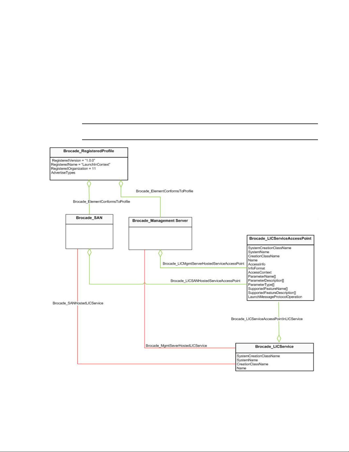
Launch In Context profile
NOTE
For example,
http:// <IP Address: port number>/webstart/<JNLP file name>?module=<module name>&<SSO
parameters if any>&${<parameter name like “WWN”>}
The corresponding entries in Brocade_LICServiceAccessPoint.ParameterName is of the following
format.
{<OrgName>:<SpecName>:<SpecVersion>:WWN}.
You have to replace the ${WWN} part of URL. Here, orgName is Brocade; specName and
specVersion are empty. Therefore, the ParameterName is Brocade:::<WWN>
Extrinsic methods of launch service are not supported.
3
FIGURE 26 Launch In Context registration and data model
Brocade Network Advisor SMI Agent Developer’s Guide 55
53-1003159-01
Page 72

CEE switch support
3
CEE switch support
The Brocade CEE switch behaves as both an FC switch and an Ethernet switch. The FC capabilities
are captured through the Switch profile. This is now enhanced to model the switch's Ethernet
capabilities.
The CEE switch is partitioned into an Ethernet Admin Domain and a Fibre Channel fabric, where the
Ethernet Admin Domain does not have any contained domain association. Only the Fibre Channel
fabric is associated to the SAN instance. Brocade_SAN.name is the principle WWN of the Fibre
Channel fabric.
Registration
Refer to “Registration” on page 43. The Brocade_Switch instance representing the CEE switch is
associated to the Brocade_RegisteredProfile instance for switch. There is no profile conformance
for the Ethernet portion of the model due to evolving standards.
Data model
Figure 27 shows the FC and Ethernet topologies along with their connections to the physical
elements. This is a general model that covers device and switch connections to the CEE switch:
• Two CIM_ComputerSystem instances (Brocade_Switch and Brocade_EthernetSwitch) is shown
to represent the FC and Ethernet sides of the switch. These instances are associated to the
physical counterpart, which is the Brocade_PhysicalComputerSystem.
• Brocade_EthernetSwitch is a component of Brocade_EthernetAdminDomain on the Ethernet
topology side. Similarly, the Brocade_Switch is a component of Brocade_Fabric on the FC
topology side.
• The value of the dedicated property of Brocade_EthernetSwitch is “Ethernet switch” (38).
• The Ethernet ports is shown as Brocade_EthernetPort instances associated to the physical
counterpart, which is the Brocade_PCSNetworkPort.
• The virtual FCoE port is represented as the Brocade_SwitchFCPort instance with the PortType
as G, or F, or E and is not be associated to a Brocade_PCSNetworkPort. It is an internal port
and there is no physical representation for that port. Even though the virtual FCoE ports are
internal to the switch, they will be modeled as visible switch ports in order to show the devices
physically (directly or indirectly) connected to one of the Ethernet interfaces. However, these
internal ports exist in the ASIC and the Brocade_SwitchFCPort.PortDescriminator property has
the value "8" representing that this is an internal port.
• The presence of an active FCoE session is registered as a name server node and port entry.
This is depicted in the host topology as the node and node ports.
• The Brocade_EthernetPort of the host is associated to the Brocade_NodeFCPort(s)
(HostedDependency). The Brocade_EthernetPort on the host will not have all properties
populated. All key properties are populated. Among the non-key properties, the
OperationalStatus is 2 (OK) and EnabledState is 2 (Enabled).
• All LANEndPoints are part of the EthernetLogicalNetwork in the
Brocade_EthernetAdminDomain.
56 Brocade Network Advisor SMI Agent Developer’s Guide
53-1003159-01
Page 73

CEE switch support
3
• Configuration of the virtual FCoE port is supported. It is a normal switch port instance. Each
Brocade_SwitchFCPort instance representing a virtual FCoE port is associated to
Brocade_SwitchFCPortSettings and Brocade_SwitchFCPortCapabilities instances (not shown
in Figure 27 to avoid clutter; refer to Figure 22 on page 44).
• Brocade_SwitchFCPortStats and Brocade_SwitchFCPortRateStats is not shown for virtual FCoE
ports. There is no statistics for the Ethernet interfaces due to the lack of an SMI model.
Brocade Network Advisor SMI Agent Developer’s Guide 57
53-1003159-01
Page 74

CEE switch support
3
FIGURE 27 FCoE topology diagram
58 Brocade Network Advisor SMI Agent Developer’s Guide
53-1003159-01
Page 75

CEE switch support
3
Topology supported
The Brocade Network Advisor SMI Agent supports the following use cases.
Device
• A device connected to one of the eight FC ports - The Switch profile is used to model the
Brocade CEE switch and its eight FC ports. For the devices connected to these eight FC ports,
refer to “Data model” on page 19 and “Data model” on page 46. The FC topology portion in
Figure 27 shows the classes and their associations for this use case.
• A device directly connected to one of the Ethernet ports on the CEE switch (one or multiple
FCoE login sessions open) with the device port and device node WWN for each session
registered in the NS database. Figure 27 shows elements in both the FC and Ethernet side. If
the host is registered with a FDMI host name, then the node and node port is hosted on the
platform.
• A device indirectly connected to the CEE switch (one or multiple FCoE login sessions open) with
the device port and device node WWN for each session registered in the NS database.
Figure 27 shows elements in both the FC and Ethernet side. The elements in orange cannot be
discovered. This means there is no representation of the Ethernet cloud.
Switch
• Two CEE switches connected by their FC ports.
• Two CEE switches connected by their Ethernet ports in pure Layer 2 - Both the switches must
be individually managed. The Ethernet portion in Figure 28 depicts the elements and their
connections. There will be one Brocade_EthernetAdminDomain and one
Brocade_EthernetLogicalNetwork per subnet.
Brocade Network Advisor SMI Agent Developer’s Guide 59
53-1003159-01
Page 76
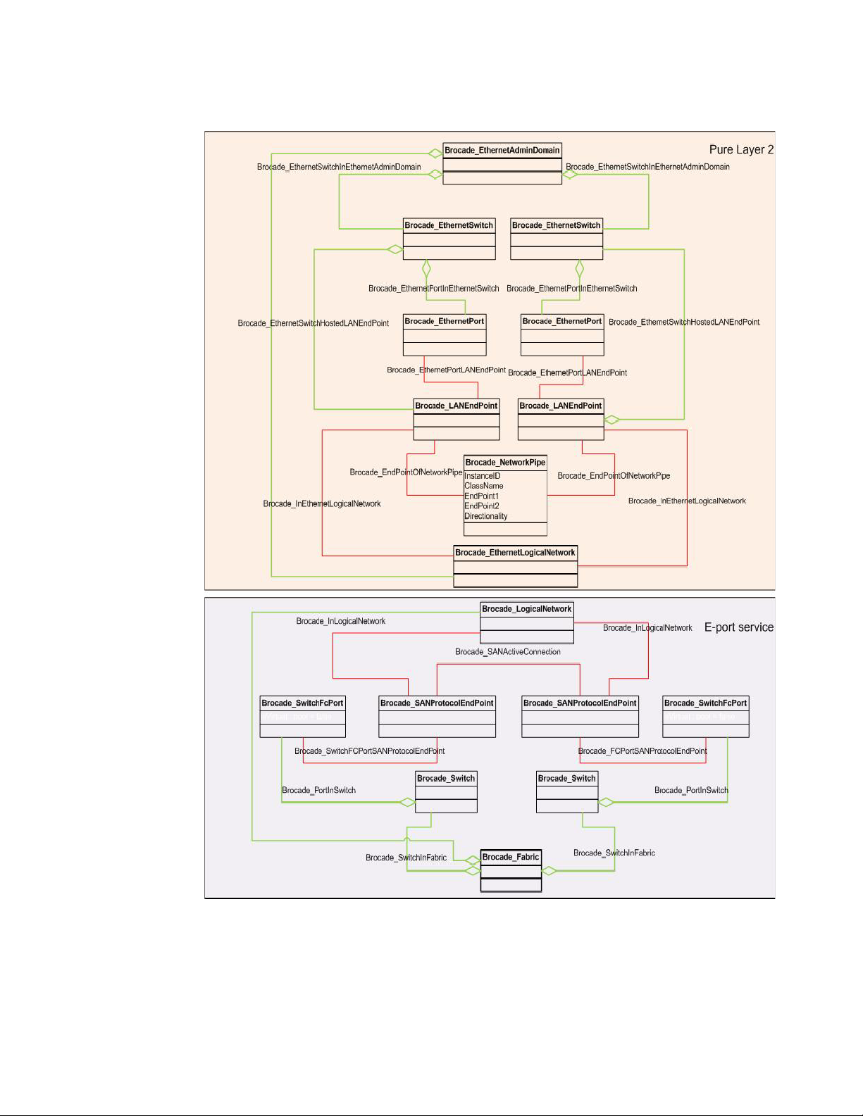
CEE switch support
3
FIGURE 28 CEE instance diagram
60 Brocade Network Advisor SMI Agent Developer’s Guide
53-1003159-01
Page 77

CEE switch support
3
Zoning support
Zoning is supported only on the front-end FC ports. The Brocade Network Advisor SMI Agent has
the same limitations as Brocade Network Advisor.
Configuration
The Brocade Network Advisor SMI Agent relies on Brocade Network Advisor support to provide CEE
configuration functionality.
All CEE configuration features are supported on Fabric OS v6.3.0 and later.
Requirements
• Enable or disable CEE port
• Set interface mode of CEE port to Layer 2 or none
• Set Layer 2 mode of CEE port to access, trunk, or converged
• Discovery of LAGs
- Create LAG
- Delete LAG
- Add members to LAG
- Remove members from LAG
• Discovery of VLANs
- Create VLAN
- Delete VLAN
- Add members to VLAN
- Remove members from VLAN
• Discovery of CEE ACL policies
- Create ACL policy
- Delete ACL policy
- Modify ACL policy
- Assign ACLs
• Discover CEE maps
- Create CEE map
- Delete CEE map
- Modify CEE map
- Assign CEE Map
• Enable global LLDP
• Disable global LLDP
• Indications
Brocade Network Advisor SMI Agent Developer’s Guide 61
53-1003159-01
Page 78

CEE switch support
3
Enabling or disabling CEE port
The CEE port is represented by Brocade_EthernetPort. The class Brocade_EthernetPort in
BrocadePartitioning.mof is updated with the following content:
• A new extrinsic method RequestStateChange is inherited from the standard CIM class
CIM_EnabledLogicalElement. This method should be used to disable or enable the CEE port.
• A new property RequestedState is inherited from the standard CIM class
CIM_EnabledLogicalElement. Knowledge of the last RequestedState is not supported for the
CEE port, thus the property will always have the value 12 (Not Applicable).
Setting interface mode of CEE port
Setting the interface mode of a CEE port is done by setting the Interface Mode property of the
Brocade_LANEndpoint associated to the CEE port. The class Brocade_LANEndPoint in
BrocadeEthernet.mof is updated with a new property InterfaceMode, which is a proprietary
property that indicates whether the CEE port is in Layer 2, Layer 3, or none mode. The property is
writable and can be set using the setInstance intrinsic operation. Layer 3 mode is not supported.
Setting Layer 2 mode of CEE port
Setting the Layer 2 mode of a CEE port is done by setting the OperationalEndpointMode property of
the Brocade_LANEndpoint associated to the CEE port. The class Brocade_LANEndpoint in
BrocadeEthernet.mof is updated with a new property OperationalEndpointMode, which is a
proprietary property that indicates whether the CEE port is in access, trunk or converged Layer 2
mode of operation. The property is writable and can be set using the setInstance intrinsic
operation.
BrocadeEthernet.mof is updated to include support for this new property.
Enabling or disabling LLDP-DCBX on Ethernet switch and CEE port
With Layer 2 networks expanding dramatically, it is difficult for a network administrator to statically
monitor and configure each device in the network. Using Link Layer Discovery Protocol (LLDP), the
network devices such as routers and switches advertise information about themselves to other
network devices and store the information they discover.
Data Center Bridging Exchange (DCBX) is used to exchange CEE-related parameters with neighbors
to achieve more efficient scheduling and a priority-based flow control for link traffic. DCBX is built
on the LLDP infrastructure and uses LLDP to exchange parameters between two link peers. DCBX
is on by default.
Brocade Network Advisor SMI Agent supports enabling or disabling the default LLDP-DCBX at the
switch and port levels. Users can enable or disable the global configuration at the switch level. User
can also enable or disable the specific LLDP configuration currently applied at the port level.
There is no support for defining any new LLDP profiles through Brocade Network Advisor SMI Agent.
Saving the running configuration to the startup configuration on the CEE switch
This feature allows you to save all the CEE configuration changes made after startup so that they
are persisted across reboots. The class Brocade_EthernetSwitch in BrocadeEthernet.mof is
updated with a new extrinsic method ConfigSaveRunningToStartup. This method saves the CEE
changes to startup configuration on the switch. The changes are visible even after a reboot.
62 Brocade Network Advisor SMI Agent Developer’s Guide
53-1003159-01
Page 79

CEE switch support
NOTE
3
Limitations
The value of LLDP-DCBX for port and switch is not persisted in Brocade Network Advisor. In order to
retrieve the value of this property, a call needs to be executed. As a result, populating this property
for port and switch during an enumerateInstances operation is costly and will lead to a degradation
in discovery timings. The Brocade Network Advisor SMI Agent will populate this property as
Unknown in both Brocade_EthernetSwitch and Brocade_EthernetPort, if the instance is retrieved
through enumerateInstances. Users can get the correct value of this property on demand through
the getInstance() intrinsic operation only.
The value of Brocade_VLANEndPoint is not persisted in Brocade Network Advisor. Brocade Network
Advisor SMI Agent will populate this property as Unknown.
LAGs
Link aggregation allows you to bundle multiple physical Ethernet links to form a single logical trunk
providing enhanced performance and redundancy. The aggregated trunk is referred to as a Link
Aggregation Group (LAG). The LAG is viewed as a single link by connected devices, the Spanning
Tree Protocol (STP), Virtual Local Area Network (VLANs), and so on. When one physical link in the
LAG fails, the other links stay up and there is no disruption to traffic.
Brocade Network Advisor SMI Agent supports discovery of these LAGs. In addition, support will be
provided to create, delete, and modify existing LAGs.
To configure links to form a LAG, the physical links must be in the same speed and all links must go
to the same neighboring device.
Data model
There is no SNIA model for LAGs. Some aspects of the Distributed Management Task Force (DMTF)
model are considered while others are completely proprietary. The following detailed notes
describe the class diagram as shown in Figure 29.
• The LAG is a protocol endpoint defined at the scope of the switch and is represented by an
instance of Brocade_LAG associated to the scoping system, which is the
Brocade_EthernetSwitch through Brocade_LAGInEthernetSwitch.
• The property Brocade_LAG.InterfaceMode indicates whether or not the LAG is in Layer 2 mode
and is writable.
• The property Brocade_LAG.OperationalEndPointMode indicates whether the LAG is in access,
trunk mode and is writable.
• Each LAG can contain zero or more members. Each LAG member is represented by an instance
of Brocade_LAGPort. The composition is through Brocade_LAGPortInLAG.
• The member is also defined at the scope of the switch associated to the scoping system, which
is the Brocade_EthernetSwitch through Brocade_EthernetSwitchHostedLAGPort.
• Each Brocade_LAGPort instance represents a concrete Brocade_LANEndPoint of a
Brocade_EthernetPort that has been added to the BrocadeLAG. This relationship between the
Brocade_LAGPort and the Brocade_LANEndPoint is represented as
Brocade_LAGPortOfLANEndPoint.
• There is one Brocade_LAGService instance per Brocade_EthernetSwitch. This hosting is
represented by Brocade_LAGServiceInEthernetSwitch.
Brocade Network Advisor SMI Agent Developer’s Guide 63
53-1003159-01
Page 80

CEE switch support
3
• The capabilities of the service are represented by an instance of
Brocade_LAGServiceCapabilities associated to the service through
Brocade_LAGServiceElementCapabilities. The maximum number of lags that can be created
on the switch and the methods supported by the service will be reported in this capabilities
instance.
• Brocade_LAGService provides extrinsic methods to create and delete LAGs, and add and
remove members from an existing LAG.
• Brocade_LAG can be created using the Brocade_LAGService.CreateLAG() extrinsic method.
Refer to BrocadeLAG.mof for details on the parameters. The path of the newly created
Brocade_LAG instance is returned in the output parameter Lag. The Brocade_LAG is
associated to the appropriate Brocade_EthernetSwitch instance on which it is defined.
• Members may be added to an existing Brocade_LAG instance using the
Brocade_LAGService.AddMembers() extrinsic method. Refer to BrocadeLAG.mof for details on
the parameters.
• Members may be removed from an existing Brocade_LAG instance using the
Brocade_LAGService.RemoveMembers() extrinsic method. Refer to BrocadeLAG.mof for details
on the parameters.
• An existing Brocade_LAG instance may be deleted using the Brocade_LAGService.DeleteLAG()
extrinsic method. This method will delete the instance and its members.
64 Brocade Network Advisor SMI Agent Developer’s Guide
53-1003159-01
Page 81
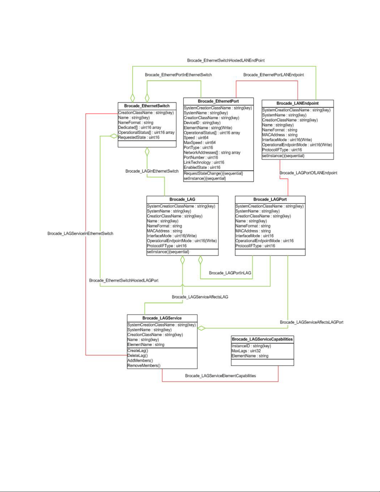
CEE switch support
3
FIGURE 29 CEE LAG class diagram
Registration
There is no conformance to any profile, and thus no registration.
Brocade Network Advisor SMI Agent Developer’s Guide 65
53-1003159-01
Page 82

CEE switch support
3
VLANs
Virtual Local Area Network (VLANs) provide the capability to overlay the physical network with
multiple virtual networks. VLANs allow you to isolate the network traffic between virtual networks
and reduce the size of administrative and broadcast domains. A VLAN contains end stations that
have a common set of requirements that are independent of physical location. You can group end
stations in a VLAN even if they are not physically located in the same LAN segment. VLANs are
typically associated with IP subnetworks and all the end stations in a particular IP subnet belong to
the same VLAN. VLAN membership is configurable on a per-interface basis.
Data model
There is no SNIA model for VLANs. Some aspects of the Distributed Management Task
Force (DMTF) model have been considered while others are completely proprietary. The following
detailed notes describe the class diagram as shown in Figure 30.
• The VLAN is a collection of protocol endpoints defined at the scope of the switch and is
represented by an instance of Brocade_VLAN associated to the scoping system, which is the
Brocade_EthernetSwitch through Brocade_VLANInEthernetSwitch.
• The property Brocade_VLAN.ElementName gives the VLAN's user-friendly name.
• Each VLAN may contain zero or more members. Each VLAN member is represented by an
instance of Brocade_VLANEndPoint. The composition is through
Brocade_VLANEndPointInVLAN.
• The member is also defined at the scope of the switch associated to the scoping system, which
is the Brocade_EthernetSwitch through Brocade_EthernetSwitchHostedVLANEndPoint.
• Each Brocade_VLANEndPoint instance represents a concrete Brocade_LAG or
Brocade_LANEndPoint of a Brocade_EthernetPort that has been added to the Brocade_VLAN.
This relationship between the Brocade_VLANEndPoint and the Brocade_LANEndPoint is
represented as Brocade_VLANEndPointOfLANEndPoint. And the relationship between the
Brocade_VLANEndPoint and the Brocade_LAG is represented as
Brocade_VLANEndPointOfLAG.
• There is one Brocade_VLANService instance per Brocade_EthernetSwitch. This hosting is
represented by Brocade_VLANServiceInEthernetSwitch.
• The capabilities of the service are represented by an instance of
Brocade_VLANServiceCapabilities associated to the service through
Brocade_VLANServiceElementCapabilities. The maximum number of VLANs that can be
created on the switch and the methods supported by the service are reported in this
capabilities instance.
• Brocade_VLANService provides extrinsic methods to create and delete VLANs, and add and
remove members from an existing VLAN.
• Brocade_VLAN can be created using the Brocade_VLANService.CreateVLAN() extrinsic method.
Refer to mof content for details on the parameters.
• The path of the newly created Brocade_VLAN instance is returned in the output parameter
VLAN. The Brocade_VLAN will be associated to the appropriate Brocade_EthernetSwitch
instance on which it is defined.
• Members may be added to an existing Brocade_VLAN instance using the
Brocade_VLANService.AddMembers() extrinsic method. Refer to BrocadeLAG.mof for details
on the parameters.
66 Brocade Network Advisor SMI Agent Developer’s Guide
53-1003159-01
Page 83

CEE switch support
• Members can be removed from an existing Brocade_VLAN instance using the
Brocade_VLANService.RemoveMembers() extrinsic method. Refer to BrocadeLAG.mof for
details on the parameters.
• An existing Brocade_VLAN instance may be deleted using the
Brocade_VLANService.DeleteVLAN() extrinsic method. This method will delete the instance
and its members.
3
Brocade Network Advisor SMI Agent Developer’s Guide 67
53-1003159-01
Page 84

CEE switch support
3
FIGURE 30 CEE VLAN class diagram
68 Brocade Network Advisor SMI Agent Developer’s Guide
53-1003159-01
Page 85

CEE switch support
Registration
There is no conformance to any profile, and thus no registration.
Limitations
The following are the limitations of VLAN profile:
• The properties are provided through the capabilities on the endpoint.
• There is no support for Generic VLAN Registration Protocol (GVRP) and so the
Brocade_VLANEndPointCapabilities.Dot1QTagging is false. Therefore,
Brocade_VLANEndPoint.GVRPStatus is not applicable.
• Brocade_VLANEndPointCapabilities.Dot1QAcceptableVLANFramesTypes is same as
Brocade_VLANEndPoint.FrameType.
• Valid values for Brocade_VLANEndPointCapabilities.Dot1QAcceptableVLANFramesTypes is
populated on Enumerate Instance Names and Enumerate Instances only. The value is
Unknown on GetInstance due to performance issue.
• Ingress and egress filtering is always enabled.
CEE ACLs
3
Access Control List (ACL) is used to filter Ethernet traffic of the Ethernet switch. It permits or denies
incoming packets from passing through interfaces that has the ACL policies applied to them. The
primary function is to control the movement of packets through or to the system and also to track
the packet movement.
ACLs are not effective until they are applied to an interface. One can apply ACLs on VLANs and on
the Ethernet switch 10-Gigabit Ethernet Layer 2 interfaces (Physical interfaces, Logical interfaces,
and LAGs). Each ACL is a unique collection of permit and deny statements (rules) that apply to the
packets. When a packet is received on an interface, the switch compares the fields in the packet
against any ACLs applied to the interface to verify that the packet has the required permissions to
be forwarded. The switch compares the packet sequentially against each rule in the ACL and either
forwards the packet or drops the packet.
The Brocade Network Advisor SMI Agent supports the discovery of these ACLs, both standard and
extended. In addition, support is provided to create, delete, and modify existing ACLs.
Resequencing of an ACL is not supported. Displaying and clearing of the ACL statistics counter is
not supported. However, users can enable or disable the tracking of traffic by specifying the count
parameter within the rule of an ACL policy.
There are two types of Layer 2 Media Access Control (MAC) address ACLs, standard and extended.
• Layer 2 standard ACLs-permit and deny traffic according to the source MAC address in the
incoming frame. Use standard MAC ACLs if you only need to filter traffic based on source MAC
addresses.
• Layer 2 extended ACLs-permit and deny traffic according to the source and destination MAC
addresses in the incoming frame, as well as other information in the MAC header, such as
EtherType.
• The ACL name must be unique across both the standard and extended types.
• The ACL name can be a maximum of 64 characters.
• Special characters can be used in an ACL name.
Brocade Network Advisor SMI Agent Developer’s Guide 69
53-1003159-01
Page 86

CEE switch support
3
• Even though ACLs can be Layer 2-specific (MAC) or Layer 3-specific (IP), they can only be
applied on the same type of interface. Because an interface can only be set to Layer 2 mode,
Layer 2 ACLs and only ACLs with MAC source and destination addresses are supported.
Data model
There is no SNIA model for CEE ACLs. The DMTF DSP1039 version 1.0.0 for the Role-Based
Authorization Profile to model these ACLs will be followed. All mandatory classes and properties as
stated in this profile will be supported. The following detailed notes describe the class diagram as
shown in Figure 31.
• The CEE ACL policy is defined at the scope of the switch. This policy represented by an instance
of Brocade_CEEACLPolicy is associated to the scoping system, which is the
Brocade_EthernetSwitch through Brocade_CEEACLPolicyInEthernetSwitch.
• Each CEE ACL policy may contain zero or more rules. All the rules within a policy are
represented by a single instance of Brocade_CEEACLRules. The composition is through
Brocade_CEEACLRulesInPolicy. There is one instance of Brocade_CEEACLRules for every
Brocade_CEEACLPolicy on the Brocade_EthernetSwitch.
• The Brocade_CEEACLRules.ActivityQualifiers array contains an array of strings, each string
represents one rule within the policy. Each string contains the details of the sequence number,
source, destination, count, Ether Type and privilege of the rule in a specific format.
• The Brocade_CEEACLRules.QualifierFormats array contains an array of strings, each string
represents the format for the rule in the Brocade_CEEACLRules.ActivityQualifiers array at the
same index.
• All the possible values for the Brocade_CEEACLRules.QualifierFormats array are published in
the Brocade_CEEACLServiceCapabilities.QualifierFormatsSupported as an array of strings. The
value in the Brocade_CEEACLRules.QualifierFormats property is a subset of these formats.
• A policy may be empty. In such a case, the Brocade_CEEACLPolicy is associated to a
Brocade_CEEACLRules instance in which the Brocade_CEEACLRules.ActivityQualifiers and
Brocade_CEEACLRules.QualifierFormats properties are empty.
• If a CEE ACL policy has been applied to a port, LAG or VLAN, this information can be discovered
by traversing the Brocade_CEEACLPolicyOnEthernetPort, Brocade_CEEACLPolicyOnLAG, or
Brocade_CEEACLPolicyOnVLAN respectively to the appropriate ManagedElement.
• For every Brocade_EthernetSwitch instance, there is an instance of Brocade_CEEACLService.
This service provides the ability to create, delete, modify, and assign CEE ACL policies.
• The capabilities of the service are published by a single instance of
Brocade_CEEACLServiceCapabilities associated to the service through
Brocade_CEEACLServiceElementCapabilities.
• Brocade_CEEACLPolicy can be created using the Brocade_CEEACLService.CreateRole()
extrinsic method. Only the input parameters RoleTemplate and Privileges are supported. The
successful execution of this method results in the creation of an instance of
Brocade_CEEACLPolicy being associated to an instance of Brocade_CEEACLRules. The path of
the newly created Brocade_CEEACLPolicy instance is returned in the output parameter Role.
The Brocade_CEEACLPolicy is associated to the appropriate Brocade_EthernetSwitch instance
on which it is defined. The Brocade_CEEACLPolicy instance is not associated to a port, LAG or
VLAN. This is done as a separate operation.
70 Brocade Network Advisor SMI Agent Developer’s Guide
53-1003159-01
Page 87

CEE switch support
• An existing Brocade_CEEACLPolicy instance may be modified using the
Brocade_CEEACLService.ModifyRole() extrinsic method. The input parameters Role and
Privileges are required. Refer to MOF content for details on the parameters. The call replaces
the existing Brocade_CEEACLRules instance for the Brocade_CEEACLPolicy specified in the
input parameter Role with the instance of Brocade_CEEACLRules specified in the input
parameter Privileges. Assigning to targets is not supported during modification. This can be
done separately through the AssignRoles operation.
• An existing Brocade_CEEACLPolicy instance may be deleted using the
Brocade_CEEACLService.DeleteRole() extrinsic method. This method deletes the instance and
its associated rules.
• A Brocade_CEEACLPolicy may be applied to an Ethernet port, LAG, or VLAN using the
Brocade_CEEACLService.AssignRoles() extrinsic method. Only one policy can be applied at a
time on a Managed Element.
3
FIGURE 31 CEE ACL class diagram
Brocade Network Advisor SMI Agent Developer’s Guide 71
53-1003159-01
Page 88

CEE switch support
3
Registration
Because the DMTF DSP 1039 version 1.0.0 for Role-Based Authorization Profile to model these
ACLs is being followed, conformance will be advertised to that profile. Figure 32 shows the profile
registration diagram.
FIGURE 32 CEE ACL profile registration
CEE maps
Data model
There is no SNIA model for CEE maps. The following notes present details on the class diagram in
Figure 33.
• The CEE map is defined at the scope of the switch. This map is represented by an instance of
Brocade_CEEMap associated to the scoping system, which is the Brocade_EthernetSwitch
through Brocade_CEEMapInEthernetSwitch.
• Each CEE map can contain zero or more priority groups. All the priority groups within a map are
represented by a single instance of Brocade_PriorityGroups. The composition is through
Brocade_ PriorityGroupsInCEEMap. There will be one instance of Brocade_PriorityGroups for
every Brocade_CEEmap on the Brocade_EthernetSwitch.
• The Brocade_PriorityGroups.ActivityQualifiers array will contain an array of strings, each string
representing one priority group within the map with the exception of the last entry. The last
entry will contain the priorities for the mapping of the priority groups to the incoming
Converged OS (COS). Each string representing a priority group will contain the details of the
bandwidth and Priority Flow Control (PFC) in a specific format. The last string representing the
priority table will contain the priority group ID for incoming CoS in a specific format.
• The Brocade_PriorityGroups.QualifierFormats array will contain an array of strings, each string
representing the format for the priority group or the priority table in the
Brocade_PriorityGroups.ActivityQualifiers array at the same index.
• All the possible values for the Brocade_PriorityGroups.QualifierFormats array are published in
the Brocade_CEEMapServiceCapabilities.QualifierFormatsSupported as an array of strings.
The value in the Brocade_PriorityGroups.QualifierFormats property is a subset of these
formats.
• A CEE map can be empty. In such a case, the Brocade_CEEMap will be associated to a
Brocade_PriorityGroups instance in which the Brocade_PriorityGroups.ActivityQualifiers and
the Brocade_PriorityGroups.QualifierFormats properties will be empty.
72 Brocade Network Advisor SMI Agent Developer’s Guide
53-1003159-01
Page 89

CEE switch support
3
• If a CEE map has been applied to a port, this information can be discovered by traversing the
Brocade_CEEMapOnEthernetPort to the Brocade_EthernetPort instance.
• For every Brocade_EthernetSwitch instance, there will be an instance of
Brocade_CEEMapService. This service will provide the ability to create, delete, modify, and
assign CEE maps.
• The capabilities of the service are published by a single instance of
Brocade_CEEMapServiceCapabilities associated to the service through
Brocade_CEEMapServiceElementCapabilities.
• Brocade_CEEMap can be created using the Brocade_CEEMapService.CreateRole() extrinsic
method. Only the input parameters RoleTemplate and Privileges are supported. The successful
execution of this method results in the creation of an instance of Brocade_CEEMap being
associated to an instance of Brocade_PriorityGroups. The path of the newly created
Brocade_CEEMap instance is returned in the output parameter Role. The Brocade_CEEMap
will be owned by the Brocade_EthernetSwitch instance on which it is defined. The
Brocade_CEEMap instance will not be associated to any port. That assignment must be done
as a separate operation. Refer to BrocadeCEEMaps.mof description for more details.
• An existing Brocade_CEEMap instance may be modified using the
Brocade_CEEMapService.ModifyRole() extrinsic method. The input parameters Role and
Privileges are required. The call will replace the existing Brocade_PriorityGroups instance for
the Brocade_CEEMap specified in the input parameter Role with the instance of
Brocade_PriorityGroups specified in the input parameter Privileges. Assigning to targets is not
supported during modification. This can be done separately through the AssignRoles
operation.
• An existing Brocade_CEEMap instance can be deleted using the
Brocade_CEEMapService.DeleteRole() extrinsic method. This method deletes the instance and
its associated priority groups.
• A Brocade_CEEMap may be applied to an Ethernet port using the
Brocade_CEEMapService.AssignRoles() extrinsic method. Only one map can be applied at a
time on the port.
Brocade Network Advisor SMI Agent Developer’s Guide 73
53-1003159-01
Page 90

CEE switch support
3
FIGURE 33 CEE map class diagram
Registration
There is no conformance to any profile, and thus no registration.
Brocade 8470 FCoE embedded switch support
Brocade 8470 is the Brocade CEE high speed switching module. CEE discovery and configuration
support is similar to that of the Brocade 8000 and FCOE10-24 as detailed in the previous sections.
There are some distinct differences in Brocade 8470. The following sections provide more details.
Differences from Brocade 8000 and FCoE 10-24
• The CEE ports are categorized into two types, internal ports and external ports.
• There are eight external CEE ports with the default name starting with "ExT <slot>/<port>".
• There are 14 or 12 internal CEE ports (BCH or BCH T chassis) with the default name starting
with "InT <slot>/<port>".
74 Brocade Network Advisor SMI Agent Developer’s Guide
53-1003159-01
Page 91

CEE switch support
NOTE
3
• Brocade 8470 supports Layer 3 mode of operation. The external ports and LAGs can be in
None, Layer 2 and Layer 3 Interface mode. However, the internal ports can only be in the Layer
2 Interface mode.
• SetInstance of the interface mode on external ports to None and Layer 2 is supported.
Support for setting of Layer 3 mode is not needed because adding of an IP address to an
ethernet port automatically puts the port in Layer 3 mode.
• SetInstance of an interface mode on LAGs to None and Layer 2 is supported.
• SetInstance of an OperationalEndPoint mode on external ports to access, trunk, and
converged mode is supported.
• SetInstance of an interface mode on internal ports is not supported. They are default to Layer
2 mode.
• Support for setting of Layer 3 mode is not required because adding of an IP address to a lag
automatically puts the lag in Layer 3 mode.
• Setting on the OperationalEndPoint mode on internal ports is not supported. They are
defaulted to a converged mode.
• The external ports are associated to PCSNetworkPort similar to those on the Brocade 8000
and FCOE10-24. However, the internal ports are not associated to PCSNetworkPort.
• The LANendpoints of external ports can be part of a LAG similar to those on the Brocade 8000
and FCOE10-24. However, the lanendpoints of internal ports cannot be part of a LAG.
• A management VLAN by default with VLANID = 4095 exists Brocade 8470.
• Creation and deletion of VLAN is not supported for Brocade 8470.
• The internal ports are part of this 4095 VLAN by default and this cannot be changed.
• The external ports cannot be added to this 4095 VLAN.
• The LANendpoints of external ports can be part of any other VLAN similar to those on the
Brocade 8000 and FCOE10-24. However, the LANendpoints of internal ports cannot be a part
of any other VLAN.
• The external and internal ports can be assigned a CEEACLPolicy.
• The external and internal ports can be assigned a CEEMap.
Support for Layer 3 features
The Brocade 8470 platform supports some of the basic Internet Protocol version 4 (IPv4) features.
Brocade Network Advisor SMI Agent supports a subset of these as stated in this section.
Brocade Network Advisor SMI Agent supports the configuration of IP addresses on Physical
interfaces such as CEE port and LAG. One can assign a single primary IP address and up to 255
secondary IP addresses on a single interface. When an IP address is assigned to an interface, it
becomes a Layer 3 interface.
Data model
The following data model is supported. Figure 34 shows the classes and associations for discovery
and configuration of IPv4 addresses on CEE ports and LAGs.
Brocade Network Advisor SMI Agent Developer’s Guide 75
53-1003159-01
Page 92
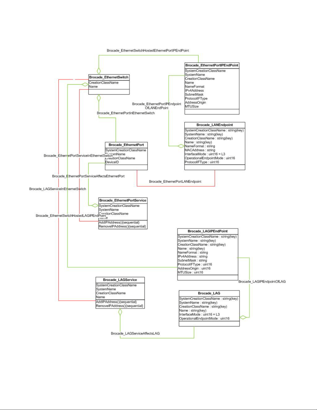
CEE switch support
3
FIGURE 34 CEE Brocade 8470 support data model
76 Brocade Network Advisor SMI Agent Developer’s Guide
53-1003159-01
Page 93

Brocade 8428 FCoE embedded switch support
Brocade 8428 is the Brocade CEE high speed switching module. CEE discovery and configuration
support is similar to that of the Brocade 8000 and FCOE10-24 as detailed in the previous sections.
There are some distinct differences in Brocade 8428. For more information about the differences,
refer to “Differences from Brocade 8000 and FCoE 10-24” on page 74, “Support for Layer 3
features” on page 75, and “Data model” on page 75.
Fabric switch partitioning subprofile
This subprofile models all Brocade switches. Every Brocade switch is partitioned into a logical
Brocade_Switch and a physical Brocade_PhysicalComputerSystem instance associated through
HostedDependency. In addition, every port is partitioned into a logical Brocade_SwitchFCPort and
physical Brocade_PCSNetworkPort instance associated through CIM_HostedDependency.
Data model
Figure 35 shows the fabric switch partitioning subprofile data model.
Fabric switch partitioning subprofile
3
FIGURE 35 Fabric switch partitioning subprofile data model
Registration
Only instances of Brocade_PhysicalComputerSystem that are Virtual Fabrics-enabled are
associated to the Brocade_RegisteredSubProfile instance for fabric switch partitioning. Figure 36
shows the registration for fabric switch partitioning subprofile.
Brocade Network Advisor SMI Agent Developer’s Guide 77
53-1003159-01
Page 94

FC routing
3
FC routing
FIGURE 36 Fabric switch partitioning profile registration
A Fibre Channel Router (FCR) is a specific case of switch partitioning. The FC-FC routing service
provides connectivity to devices in different fabrics without merging the fabrics. A switch running
the FC-FC routing service is called a Fibre Channel Router.
Data model
Figure 37 shows the FCR data model.
78 Brocade Network Advisor SMI Agent Developer’s Guide
53-1003159-01
Page 95

FC routing
3
FIGURE 37 Fibre Channel Router data model
• FCR devices of Brocade act as normal switches and routers. Therefore, the switch which is
router capable and functioning in multi-domain mode, has both physical and logical
representation in SMIS. The FCR is represented by two instances of CIM_ComputerSystem, a
Brocade_Switch and a Brocade_PhysicalComputerSystem associated by
CIM_HostedDependency(Brocade_SwitchInPCS).
• The Brocade_PhysicalComputerSystem, in addition to being associated to the BackBone
Brocade_Switch instance, will also be associated to Brocade_Switch instances of front and
xlate phantoms.
• Both the xlate phantom and front phantom switches are represented as Brocade_Switch
instances. The front phantom domain and xlate phantom domain switches are associated by
the Brocade_SANActiveConnection. These phantom switches can be differentiated by
Brocade_Switch.OtherIdentifyingInfo property value (which would have the values as Transla te
Domain, Front Domain, and None for translate phantom domain, front phantom domain, and
ordinary switches respectively).
• The InteropMode property of front phantom domain and xlate phantom domain switches are
not populated.
Brocade Network Advisor SMI Agent Developer’s Guide 79
53-1003159-01
Page 96

3
FC routing
• Brocade_PCSServiceCapabilities has a Boolean property called FCRCapable. If the property is
true, then the switch is FCR capable and is enabled. If false, the switch is capable and not
enabled. If null, the switch is not FCRcapable. In the case of VF setup, this property is null if the
base switch is not discovered.
• Each phantom switch is associated with Brocade_FCSwitchSettings and
Brocade_FCSwitchCapabilities. The FCSwitchSettings has the property called
PreferredDomainID, which is a settable property. A user can set the PreferredDomainID for the
phantom switches in the FCSwitchSettings instance. If the DomainIDConfigurable is true then
it would indicate that the DomainID settings can be modified. Modifying this property is a
fabric-disruptive operation due to intrinsically disabling of all EX_Ports connected to the
respective edge fabric, modifying the domain ID of the phantom switch, and then enabling all
the EX_Ports as required by the firmware. This applies to both the front and translate phantom
domains. In addition, by modifying the translate domain ID, and the need to disable or enable
the EX_Ports, the WWN of the translate domain is changed.
• A port on FCR configured as an EX_Port is filtered out during port discovery on the backbone
for edge to edge device sharing.
• An association called Brocade_SwitchFCPortOfPCSNetworkPort associates the front phantom
SwitchFCPort instance representing the FCR EX_Port in the edge fabric with the
PCSNetworkPort instance representing the FCR EX_Port on the FCR logical switch.
• There is one instance of NodeFCPort for every entry in the name server. The SystemName
property reflects the Fabric WWN of the fabric where the port exists. In case of FCR setup,
where the devices are imported or exported, there may be multiple instances of NodeFCPort
where DeviceID is the same, but SystemName differentiates each instance based on fabric
membership.
• The physical ports are represented as Brocade_PCSNetworkPort instances. In the backbone
view for every physical port, there is a CIM_NetworkPortCapabilities, identifying the
configuration capabilities of the port; and a CIM_NetworkPortSettings, identifying the
configuration details of that port. This class can be used to enable configuration of an FCR port
as an EX_Port by writing to the NetworkIDs property of the port's settings. Modifying this
property is a fabric-disruptive operation due to intrinsically disabling the EX_Port, modifying the
value, and then enabling the EX_Port as required by the firmware.
• The property NetworkIDsConfigurable will indicate whether or not a port in the fabric is capable
of being configured.
• From an SMI perspective, all fabrics which are physically connected are considered to be
contained in the same SAN.
• If FCR setup where the backbone fabric and edge fabrics have been discovered -
Brocade_SAN.Name is the principal WWN of the backbone fabric.
• If FCR setup where only one or more edge fabrics have been discovered - In the absence of the
backbone, there is no knowledge that the edge fabrics belong to one FCR backbone fabric, so
each edge fabric will be associated to its own SAN instance Brocade_SAN.Name which is the
principal WWN of that edge fabric.
Registration
Brocade_RegisteredProfile is mapped to Brocade_Switch using
Brocade_ElementConformsToProfile association class if edge switch is discovered along with its
backbone.
Figure 38 shows the SNIA Profile Registration model to advertise Inter-Fabric Routing profile.
80 Brocade Network Advisor SMI Agent Developer’s Guide
53-1003159-01
Page 97

FC routing
.
3
FIGURE 38 Fibre Channel Router registration model
Edge-to-edge device sharing (no FCIP configured in backbone)
Figure 39 shows the instance diagram which depicts fabric discovery of the backbone and edge
fabric with edge to edge device sharing.
A port on FCR configured as an EX_Port is filtered out during port discovery on the backbone for
edge-to-edge device sharing.
If only the backbone fabric is being managed through Brocade Network Advisor, then only
instances in the BackBone Fabric view are discovered. For edge fabric managed through Brocade
Network Advisor, refer to the “Limitations” section. If both the backbone and the edge fabrics are
managed through Brocade Network Advisor, then all instances and associations are discoverable.
Brocade Network Advisor SMI Agent Developer’s Guide 81
53-1003159-01
Page 98

3
FC routing
FIGURE 39 Data model for edge-to-edge device sharing
82 Brocade Network Advisor SMI Agent Developer’s Guide
53-1003159-01
Page 99

FC routing
3
Backbone-to-edge device sharing (no FCIP configured in backbone)
• Figure 40 shows the data model for backbone-to-edge device sharing. If only the backbone
fabric is being managed through Brocade Network Advisor, then only instances in the
BackBone fabric view are discovered. If only the edge fabric is being managed through
Brocade Network Advisor, refer to the “Limitations” section. If both the backbone and the edge
fabrics are being managed through Brocade Network Advisor, then all instances and
associations are discoverable.
• In the case of backbone edge device sharing, there is only one front phantom domain and two
xlate phantom domain switches. On the Edge fabric side, there is one front domain and one
xlate domain switch instance created. On the BackBone fabric side, there is only an xlate
domain switch created and no front phantom domain. Because the xlate phantom domain
switch is always behind the front phantom domain switch, the backbone switch itself
represents the front phantom domain. In addition to the logical port instance on the front
phantom in the edge fabric, FOS creates another instance of the logical port on the backbone
logical switch. This is the logical port instance that is connected to another logical port
instance on the xlate phantom through a SANActiveConnection.
Brocade Network Advisor SMI Agent Developer’s Guide 83
53-1003159-01
Page 100

3
FC routing
FIGURE 40 Data model for backbone-to-edge device sharing
84 Brocade Network Advisor SMI Agent Developer’s Guide
53-1003159-01
 Loading...