

Page 1

53-1003093-03
15 April 2014
FastIron Ethernet Switch
Traffic Management Guide
Supporting FastIron Software Release 08.0.10b
Page 2

Page 3

Contents
Preface.....................................................................................................................................5
Document conventions......................................................................................5
Text formatting conventions.................................................................. 5
Command syntax conventions.............................................................. 5
Notes, cautions, and warnings.............................................................. 6
Brocade resources............................................................................................ 7
Getting technical help........................................................................................7
Document feedback.......................................................................................... 7
About This Document................................................................................................................ 9
About This Document........................................................................................9
What’s new in this document.......................................................................... 10
How command information is presented in this guide.....................................10
Quality of Service.................................................................................................................... 11
Supported Quality of Service features............................................................ 11
QoS overview..................................................................................................12
Processing of classified traffic.............................................................12
QoS for Brocade stackable devices................................................................ 19
QoS profile restrictions in a traditional stack....................................... 19
QoS behavior for trusting Layer 2 (802.1p) in a traditional stack........ 19
QoS behavior for trusting Layer 3 (DSCP) in a traditional stack ........ 19
QoS behavior on port priority and VLAN priority in a traditional
stack.............................................................................................. 19
QoS behavior for 802.1p marking in a traditional stack...................... 20
QoS queues.................................................................................................... 20
Queues for the SX-FI48GPP interface module................................... 20
Queues for the SX-FI-8XG interface module...................................... 21
Queues for the ICX 6430 switch......................................................... 22
User-configurable scheduler profile.................................................... 23
QoS priorities-to-traffic assignment.................................................................27
Changing a port priority.......................................................................27
Assigning static MAC entries to priority queues..................................28
Buffer allocation and threshold for QoS queues................................. 28
802.1p priority override................................................................................... 28
Configuration notes and feature limitations ........................................29
Enabling 802.1p priority override........................................................ 29
Marking........................................................................................................... 29
DSCP and CoS global remarking....................................................................29
Configuration considerations and limitations.......................................30
Enabling DSCP marking..................................................................... 30
Example: DSCP marking.................................................................... 30
Enabling CoS marking........................................................................ 31
Example: CoS marking....................................................................... 31
DSCP-based QoS configuration..................................................................... 31
Application notes for DSCP-based QoS............................................. 31
Using ACLs to honor DSCP-based QoS.............................................32
FastIron Ethernet Switch Traffic Management Guide
53-1003093-03
1
Page 4

Trust DSCP for the SX-FI48GPP, SX-FI-24GPP, SX-FI-24HF,
SX-FI-2XG, and SX-FI8XG modules...........................................32
Configuring QoS mapping configuration....................................................... 33
Default DSCP to internal forwarding priority mappings.....................33
Changing the DSCP to internal forwarding priority mappings...........34
Changing the VLAN priority 802.1p to hardwareforwarding
queue mappings..........................................................................35
Default scheduling configuration for the SX-FI48GPP module......... 36
Default scheduling configuration for the ICX 6430............................36
Scheduling QoS information......................................................................... 37
Scheduling for the SX-FI48GPP module.......................................... 37
QoS queuing methods...................................................................... 37
Selecting the QoS queuing method.................................................. 39
Configuring the QoS queues.............................................................39
Viewing QoS settings....................................................................................41
Viewing DSCP-based QoS settings..............................................................42
Rate Limiting and Rate Shaping on FastIron X Series and FCX and ICX Series Switches...........45
Supported Rate Limiting and Rate Shaping features on FastIron X
Series and FCX and ICX Series Switches...............................................45
Rate limiting overview................................................................................... 45
Rate limiting in hardware...............................................................................46
How Fixed rate limiting works........................................................... 46
Configuration notes for rate limiting.................................................. 47
Configuring a port-based rate limiting policy.....................................48
Configuring an ACL-based rate limiting policy.................................. 48
Displaying the fixed rate limiting configuration..................................48
Rate shaping overview..................................................................................50
Configuration notes for rate shaping.................................................50
Configuring outbound rate shaping for a port................................... 51
Configuring outbound rate shaping for a specific priority..................51
Configuring outbound rate shaping for a LAG port........................... 52
Displaying rate shaping configurations............................................. 52
Limiting Broadcast, Multicast, and Unknown Unicast Traffic.................................................. 53
Supported Limiting Broadcast, Multicast, and Unknown Unicast Traffic
Features.................................................................................................. 53
Configuration notes and feature limitations...................................................53
Command syntax for packet-based limiting ................................................. 54
On FastIron X-Series devices........................................................... 54
On Brocade FCX Series, ICX 6430 , and ICX 6650 devices............ 55
On Brocade ICX 6610 and ICX 6450 devices...................................55
Command syntax for byte-based limiting......................................................56
Viewing broadcast, multicast, and unknown unicast limits........................... 57
Traffic Policies...................................................................................................................... 61
Supported Traffic Policies............................................................................. 61
Traffic policies overview................................................................................61
Configuration notes and feature limitations for traffic policies...........62
Maximum number of traffic policies supported on a device.......................... 63
Setting the maximum number of traffic policies supported on a
Layer 3 device............................................................................. 64
ACL-based rate limiting using traffic policies................................................ 64
Support for fixed rate limiting and adaptive rate limiting................... 65
Configuring ACL-based fixed rate limiting.........................................65
2
FastIron Ethernet Switch Traffic Management Guide
53-1003093-03
Page 5

ACL-based adaptive rate limiting configuration...................................66
Specifying the action to be taken for packets that are over the limit... 69
ACL statistics and rate limit counting.............................................................. 70
Enabling ACL statistics....................................................................... 70
Enabling ACL statistics with rate limiting traffic policies......................71
Viewing ACL and rate limit counters................................................... 71
Clearing ACL and rate limit counters.................................................. 73
Viewing traffic policies.....................................................................................73
CPU rate-limiting............................................................................................. 75
ICX 7750 Flow control and buffer management....................................................................... 77
Priority flow control .........................................................................................77
Configuring priority flow control.......................................................................78
Packet buffer management............................................................................. 78
Traffic Management Commands..............................................................................................81
egress-buffer-profile........................................................................................ 81
ip dscp-remark ............................................................................................... 82
ip pcp-remark ................................................................................................. 82
priority-flow-control..........................................................................................83
priority-flow-control enable.............................................................................. 84
qos egress-buffer-profile................................................................................. 84
qos priority-to-pg............................................................................................. 86
qos scheduler-profile.......................................................................................87
scheduler-profile..............................................................................................90
show priority-flow-control................................................................................ 91
show qos egress-buffer-profile........................................................................91
show qos priority-to-pg....................................................................................92
show qos scheduler........................................................................................ 93
store-and-forward............................................................................................94
symmetrical-flow-control enable .....................................................................95
Index...................................................................................................................................... 97
FastIron Ethernet Switch Traffic Management Guide
53-1003093-03
3
Page 6

4 FastIron Ethernet Switch Traffic Management Guide
53-1003093-03
Page 7

Preface
● Document conventions......................................................................................................5
● Brocade resources............................................................................................................ 7
● Getting technical help........................................................................................................7
● Document feedback.......................................................................................................... 7
Document conventions
The document conventions describe text formatting conventions, command syntax conventions, and
important notice formats used in Brocade technical documentation.
Text formatting conventions
Text formatting conventions such as boldface, italic, or Courier font may be used in the flow of the text
to highlight specific words or phrases.
Format
bold text
italic text
Courier font
Description
Identifies command names
Identifies keywords and operands
Identifies the names of user-manipulated GUI elements
Identifies text to enter at the GUI
Identifies emphasis
Identifies variables and modifiers
Identifies paths and Internet addresses
Identifies document titles
Identifies CLI output
Identifies command syntax examples
Command syntax conventions
Bold and italic text identify command syntax components. Delimiters and operators define groupings of
parameters and their logical relationships.
Convention
bold text Identifies command names, keywords, and command options.
italic text Identifies a variable.
Description
FastIron Ethernet Switch Traffic Management Guide 5
53-1003093-03
Page 8
Notes, cautions, and warnings
Convention Description
value In Fibre Channel products, a fixed value provided as input to a command
option is printed in plain text, for example, --show WWN.
[ ]
{ x | y | z }
x | y
< >
...
\
Syntax components displayed within square brackets are optional.
Default responses to system prompts are enclosed in square brackets.
A choice of required parameters is enclosed in curly brackets separated by
vertical bars. You must select one of the options.
In Fibre Channel products, square brackets may be used instead for this
purpose.
A vertical bar separates mutually exclusive elements.
Nonprinting characters, for example, passwords, are enclosed in angle
brackets.
Repeat the previous element, for example, member[member...].
Indicates a “soft” line break in command examples. If a backslash separates
two lines of a command input, enter the entire command at the prompt without
the backslash.
Notes, cautions, and warnings
Notes, cautions, and warning statements may be used in this document. They are listed in the order of
increasing severity of potential hazards.
NOTE
A Note provides a tip, guidance, or advice, emphasizes important information, or provides a reference
to related information.
ATTENTION
An Attention statement indicates a stronger note, for example, to alert you when traffic might be
interrupted or the device might reboot.
CAUTION
A Caution statement alerts you to situations that can be potentially hazardous to you or cause
damage to hardware, firmware, software, or data.
DANGER
A Danger statement indicates conditions or situations that can be potentially lethal or
extremely hazardous to you. Safety labels are also attached directly to products to warn of
these conditions or situations.
6 FastIron Ethernet Switch Traffic Management Guide
53-1003093-03
Page 9

Brocade resources
Visit the Brocade website to locate related documentation for your product and additional Brocade
resources.
You can download additional publications supporting your product at www.brocade.com. Select the
Brocade Products tab to locate your product, then click the Brocade product name or image to open the
individual product page. The user manuals are available in the resources module at the bottom of the
page under the Documentation category.
To get up-to-the-minute information on Brocade products and resources, go to MyBrocade. You can
register at no cost to obtain a user ID and password.
Release notes are available on MyBrocade under Product Downloads.
White papers, online demonstrations, and data sheets are available through the Brocade website.
Getting technical help
Brocade resources
You can contact Brocade Support 24x7 online, by telephone, or by e-mail.
For product support information and the latest information on contacting the Technical Assistance
Center, go to http://www.brocade.com/services-support/index.html.
Use one of the following methods to contact the Brocade Technical Assistance Center.
Online Telephone E-mail
Preferred method of contact for nonurgent issues:
• My Cases through MyBrocade
• Software downloads and
licensing tools
• Knowledge Base
Document feedback
Required for Sev 1-Critical and Sev
2-High issues:
• Continental US:
1-800-752-8061
• Europe, Middle East, Africa,
and Asia Pacific: +800-AT
FIBREE (+800 28 34 27 33)
• For areas unable to access toll
free number: +1-408-333-6061
• Toll-free numbers are available
in many countries.
support@brocade.com
Please include:
• Problem summary
• Serial number
• Installation details
• Environment description
To send feedback and report errors in the documentation you can use the feedback form posted with
the document or you can e-mail the documentation team.
Quality is our first concern at Brocade and we have made every effort to ensure the accuracy and
completeness of this document. However, if you find an error or an omission, or you think that a topic
needs further development, we want to hear from you. You can provide feedback in two ways:
FastIron Ethernet Switch Traffic Management Guide 7
53-1003093-03
Page 10

Preface
• Through the online feedback form in the HTML documents posted on www.brocade.com.
• By sending your feedback to documentation@brocade.com.
Provide the publication title, part number, and as much detail as possible, including the topic heading
and page number if applicable, as well as your suggestions for improvement.
8 FastIron Ethernet Switch Traffic Management Guide
53-1003093-03
Page 11

About This Document
● About This Document........................................................................................................9
● What’s new in this document.......................................................................................... 10
● How command information is presented in this guide.....................................................10
About This Document
Introduction
This guide includes procedures for configuring the software. The software procedures show how to
perform tasks using the CLI. This guide also describes how to monitor Brocade products using statistics
and summary screens.
Supported Hardware
This guide supports the following product families from Brocade:
• FastIron X Series devices (chassis models):
‐ FastIron SX 800
‐ FastIron SX 1600
• Brocade FCX Series (FCX) Stackable Switch
• Brocade ICX™ 6610 (ICX 6610) Stackable Switch
• Brocade ICX 6430 Series (ICX 6430)
• Brocade ICX 6450 Series (ICX 6450)
• Brocade ICX 6650 Series (ICX 6650)
• Brocade TurboIron 24X Series
• Brocade ICX 7750 Series (ICX 7750)
For information about the specific models and modules supported in a product family, refer to the
hardware installation guide for that product family.
NOTE
The Brocade ICX 6430-C switch supports the same feature set as the Brocade ICX 6430 switch unless
otherwise noted.
NOTE
The Brocade ICX 6450-C12-PD switch supports the same feature set as the Brocade ICX 6450 switch
unless otherwise noted.
FastIron Ethernet Switch Traffic Management Guide
53-1003093-03
9
Page 12

What’s new in this document
What’s new in this document
This document includes the information from FastIron software release 08.0.10b.
Summary of Enhancements in FastIron release 08.0.10bTABLE 1
Feature Description Location
A new command has been added:
store-and-forward.
Support for Outbound rate
shaping.
The store-and-forward command
changes the switch mode to store-andforward.
Outbound rate shaping is supported
on ICX 7750 devices.
See store-and-forward on page
94.
See Configuring outbound rate
shaping for a LAG port on page 52
and Configuration notes for rate
shaping on page 50.
How command information is presented in this guide
For all new content, command syntax and parameters are documented in a separate command
reference section at the end of the publication.
In an effort to provide consistent command line interface (CLI) documentation for all products, Brocade
is in the process of preparing standalone Command References for the IP platforms. This process
involves separating command syntax and parameter descriptions from configuration tasks. Until this
process is completed, command information is presented in two ways:
• For all new content included in this guide, the CLI is documented in separate command pages.
The new command pages follow a standard format to present syntax, parameters, usage
guidelines, examples, and command history. Command pages are compiled in alphabetical order
in a separate command reference chapter at the end of the publication.
• Legacy content continues to include command syntax and parameter descriptions in the chapters
where the features are documented.
If you do not find command syntax information embedded in a configuration task, refer to the
command reference section at the end of this publication for information on CLI syntax and usage.
10 FastIron Ethernet Switch Traffic Management Guide
53-1003093-03
Page 13

Quality of Service
● Supported Quality of Service features............................................................................ 11
● QoS overview..................................................................................................................12
● QoS for Brocade stackable devices................................................................................ 19
● QoS queues.................................................................................................................... 20
● QoS priorities-to-traffic assignment.................................................................................27
● 802.1p priority override................................................................................................... 28
● Marking........................................................................................................................... 29
● DSCP and CoS global remarking....................................................................................29
● DSCP-based QoS configuration..................................................................................... 31
● Configuring QoS mapping configuration......................................................................... 33
● Scheduling QoS information........................................................................................... 37
● Viewing QoS settings...................................................................................................... 41
● Viewing DSCP-based QoS settings................................................................................ 42
Supported Quality of Service features
Lists the the individual BrocadeFastIron switches and the Quality of Service (QoS) features they
support.
The following table lists the individual BrocadeFastIron switches and the Quality of Service (QoS)
features they support. These features are supported in the Layer 2 and Layer 3 software images,
except where explicitly noted.
Feature ICX 6430 ICX 6450 FCX ICX 6610 ICX 6650 FSX 800
FSX 1600
802.1p Quality of Service (QoS): Strict
Priority (SP), Weighted Round Robin
(WRR), Combined SP and WRR, 8
priority queues
802.1p priority override 08.0.01 08.0.01 08.0.01 08.0.01 08.0.01 08.0.01
802.1p marking 08.0.01 08.0.01 08.0.01 08.0.01 08.0.01 08.0.01
DiffServ support 08.0.01 08.0.01 08.0.01 08.0.01 08.0.01 08.0.01
DSCP-based QoS 08.0.01 08.0.01 08.0.01 08.0.01 08.0.01 08.0.01
DSCP and PCP global remarking 08.0.01 08.0.01 08.0.01 08.0.01 08.0.01 08.0.01
QoS mappings 08.0.01 08.0.01 08.0.01 08.0.01 08.0.01 08.0.01
08.0.01 08.0.01 08.0.01 08.0.01 08.0.01 08.0.01
1
ICX 7750
08.0.10
08.0.10
08.0.10
08.0.10
08.0.10
08.0.10
08.0.10
1
3rd generation modules only.
FastIron Ethernet Switch Traffic Management Guide 11
53-1003093-03
Page 14

QoS overview
Feature ICX 6430 ICX 6450 FCX ICX 6610 ICX 6650 FSX 800
FSX 1600
User-configurable scheduler profiles 08.0.01 08.0.01 08.0.01 08.0.01 08.0.01 No
QoS overview
Quality of Service (QoS) features are used to prioritize the use of bandwidth in a switch. When QoS
features are enabled, traffic is classified as it arrives at the switch, and processed through on the basis
of configured priorities. Traffic can be dropped, prioritized for guaranteed delivery, or subject to limited
delivery options as configured by a number of different mechanisms.
This chapter describes how QoS is implemented and configured in FastIron devices.
Classification is the process of selecting packets on which to perform QoS, reading the QoS
information, and assigning a priority to the packets. The classification process assigns a priority to
packets as they enter the switch. These priorities can be determined on the basis of information
contained within the packet or assigned to the packet as it arrives at the switch. Once a packet or
traffic flow is classified, it is mapped to a forwarding priority queue.
Packets on Brocade devices are classified in up to eight traffic classes with values from 0 to 7.
Packets with higher priority classifications are given a precedence for forwarding.
ICX 7750
08.0.10
Processing of classified traffic
The trust level in effect on an interface determines the type of QoS information the device uses for
performing QoS. The Brocade device establishes the trust level based on the configuration of various
features and whether the traffic is switched or routed. The trust level can be one of the following:
• Ingress port default priority.
• Static MAC address.
• Layer 2 Class of Service (CoS) value - This is the 802.1p priority value in the Ethernet frame. It
can be a value from 0 through 7. The 802.1p priority is also called the Class of Service .
• Layer 3 Differentiated Services Code Point (DSCP) - This is the value in the six most significant
bits of the IP packet header 8-bit DSCP field. It can be a value from 0 through 63. These values
are described in RFCs 2472 and 2475. The DSCP value is sometimes called the DiffServ value .
The device automatically maps the DSCP value of a packet to a hardware forwarding queue.
Refer to Viewing QoS settings on page 41.
• ACL keyword - An ACL can also prioritize traffic and mark it before sending it along to the next
hop. This is described under "QoS options for IP ACLs" section in the FastIron Ethernet Switch
Security Configuration Guide .
Given the variety of different criteria, there are many possibilities for traffic classification within a
stream of network traffic. For this reason, the priority of packets must be resolved based on which
criteria takes precedence. Precedence follows the schemes illustrated in the Determining a packet
trust level - FSX devices through Determining a packet trust level - FCX, and ICX devices figures.
Determining the trust level of a packet
Packet trust level is determined differently on FSX devices than on FCX, and ICX series devices.
The following figure illustrates how FSX devices determine the trust level of a packet.
12 FastIron Ethernet Switch Traffic Management Guide
53-1003093-03
Page 15
Quality of Service
NOTE
The Determining a packet trust level - FSX devices figure is not applicable to the third generation FSX
interface modules. To determine the trust level of a packet for the SX-FI48GPP, SX-FI-24GPP, SXFI-24HF, SX-FI-2XG, and SX-FI-8XG modules, refer to the Determining a packet trust level - SX-
FI48GPP, SX-FI-24GPP, SX-FI-24HF, SX-FI-2XG, and SX-FI-8XG modules figure.
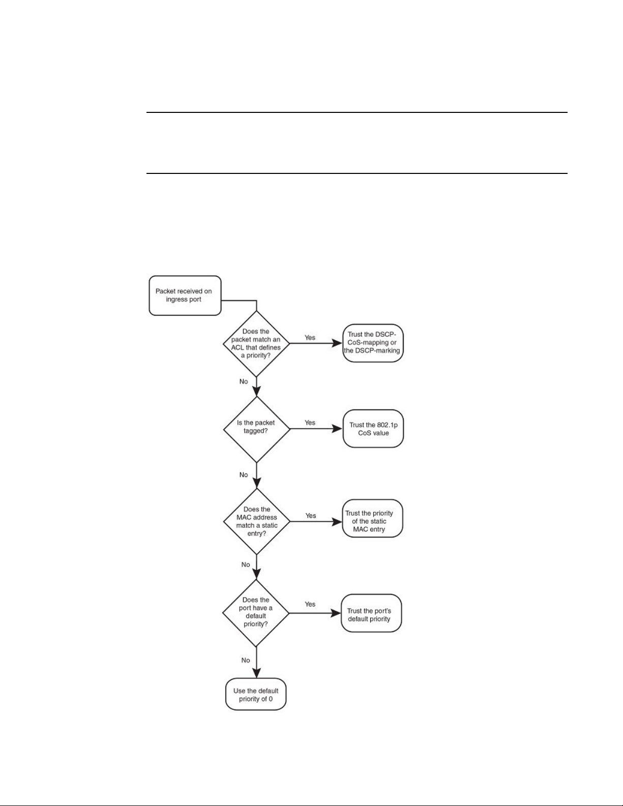
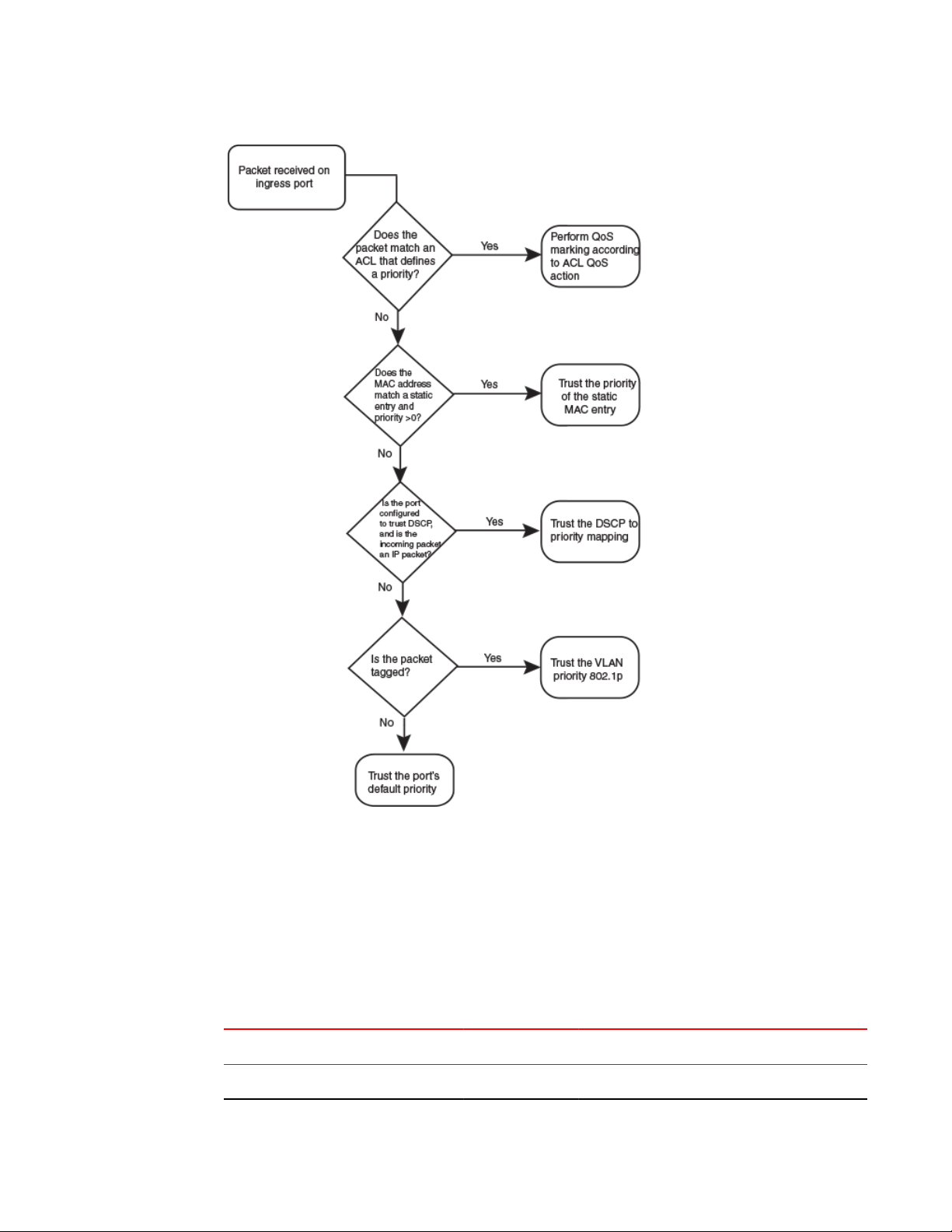
As shown in the flowchart, the first criteria considered is whether the packet matches on an ACL that
defines a priority. Next, it checks if trust DSCP is enabled on the port. If this is not the case, the packet
is next classified based on the static MAC address. If this is not true and the packet is tagged, the
packet is classified with the 802.1p CoS value. If none of these is true, the packet is next classified
based on the ingress port default priority or the default priority of zero (0).
FIGURE 1 Determining a packet trust level - FSX devices
FastIron Ethernet Switch Traffic Management Guide 13
53-1003093-03
Page 16

Quality of Service
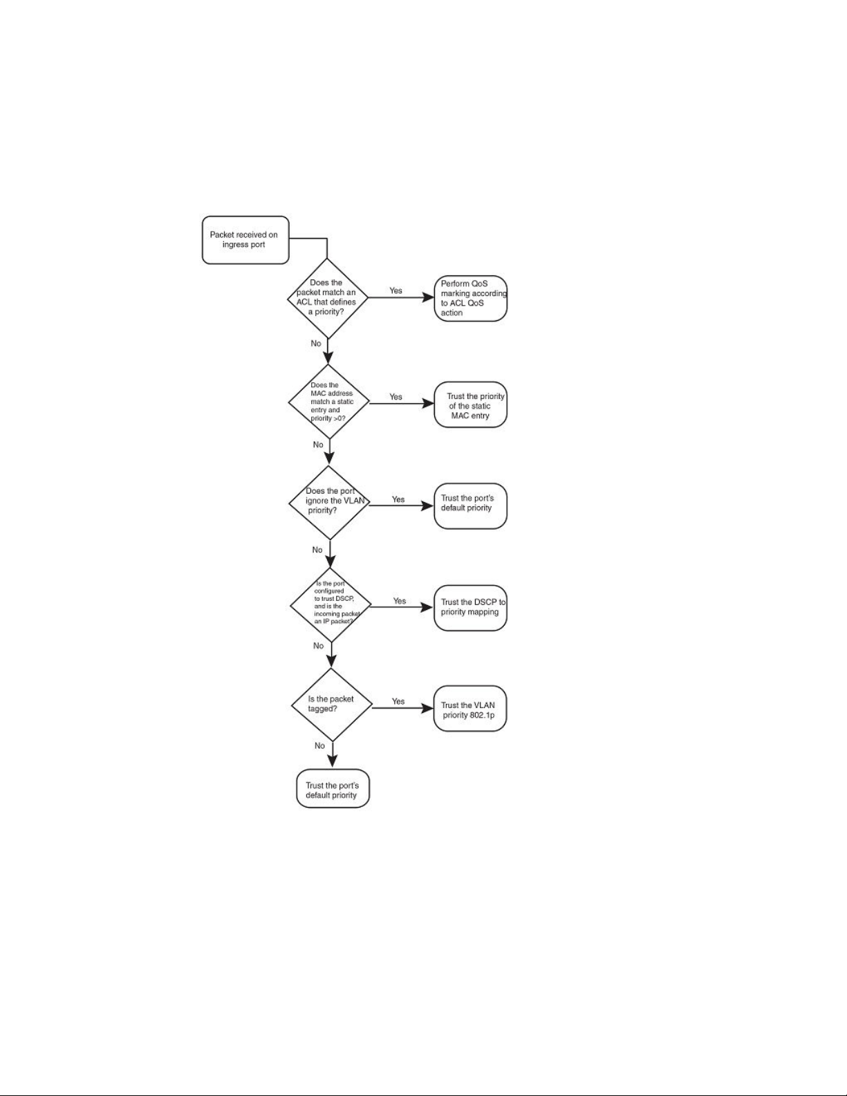
The Determining a packet trust level - SX-FI48GPP, SX-FI-24GPP, SX-FI-24HF, SX-FI-2XG, and SXFI-8XG modules figure illustrates how the SX-FI48GPP, SX-FI-24GPP, SX-FI-24HF, SX-FI-2XG, and
SX-FI-8XG modules determine the trust level of a packet. The marking process for these modules is
similar to the marking process for other FastIron SX modules. However, there are major differences
between these modules and other FastIron SX modules.
• For the SX-FI48GPP, SX-FI-24GPP, SX-FI-24HF, SX-FI-2XG, and SX-FI-8XG modules, static
MAC priority takes higher precedence than VLAN priority. For other FastIron SX modules, VLAN
priority takes higher precedence over static MAC priority.
• For other FastIron SX modules, the priority of the dynamically learned MAC address is inherited
from the default port priority. For the SX-FI48GPP, SX-FI-24GPP, SX-FI-24HF, SX-FI-2XG, and
SX-FI-8XG modules, the priority of the dynamically learned MAC address is not inherited from the
default port priority because it is not desirable to allow the port priority to take precedence over
the VLAN priority. All dynamically learned MAC addresses are assigned a priority of 0 in the SX-
14 FastIron Ethernet Switch Traffic Management Guide
53-1003093-03
Page 17
Quality of Service
FI48GPP, SX-FI-24GPP, SX-FI-24HF, SX-FI-2XG, and SX-FI-8XG modules. Therefore, configuring
a static MAC with a priority of 0 has no effect on QoS marking.
FIGURE 2 Determining a packet trust level - SX-FI48GPP , SX-FI-24GPP, SX-FI-24HF, SX-FI-2XG,
and SX-FI-8XG modules
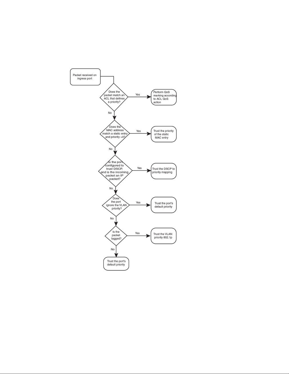
The following figure illustrates how FCX, and ICX series devices determine the trust level of a packet.
As shown in the flowchart, the first criteria considered is whether the packet matches on an ACL that
defines a priority. If this is not the case and the MAC address of the packet matches a static entry, the
packet is classified with the priority of the static MAC entry. If neither of these is true, the packet is next
FastIron Ethernet Switch Traffic Management Guide 15
53-1003093-03
Page 18
Quality of Service
classified with the ingress port default priority. then DSCP/ToS value, then 802.1p CoS value, and
finally the default priority of zero (0).
FIGURE 3 Determining a packet trust level - FCX, and ICX devices
FIGURE 4 Determining the trust level of a packet - ICX 7750 devices
16 FastIron Ethernet Switch Traffic Management Guide
53-1003093-03
Page 19
Quality of Service
Once a packet is classified, it is mapped to a forwarding queue. For all products except the SXF148GPP interface module and ICX 6430 switch, there are eight queues designated from 0 through 7.
The internal forwarding priority maps to one of these eight queues. For the SX-Fl48GPP interface
module and ICX 6430 switch, internal forwarding priority maps to four forwarding queues. The mapping
between the internal priority and the forwarding queue cannot be changed.
The following tables show the default QoS mappings for FCX platforms that are used if the trust level for
CoS or DSCP is enabled. For information on the SX-Fl48GPP interface module, refer to Queues for the
SX-FI48GPP interface module on page 20. For information on default QoS mappings for the ICX 6430
switch, refer to Queues for the ICX 6430 switch on page 22.
TABLE 2
DSCP value 0 1 2 3 4 5 6 7 8 9 10 11 12 12 14 15
802.1p (CoS) value 0 0 0 0 0 0 0 0 1 1 1 1 1 1 1 1
FastIron Ethernet Switch Traffic Management Guide 17
53-1003093-03
Default QoS mappings for FCX platforms, columns 0 to 15
Page 20

Quality of Service
Default QoS mappings for FCX platforms, columns 0 to 15 (Continued)TABLE 2
DSCP value 0 1 2 3 4 5 6 7 8 9 10 11 12 12 14 15
DSCP value 0 1 2 3 4 5 6 7 8 9 10 11 12 12 14 15
Internal forwarding priority 0 0 0 0 0 0 0 0 1 1 1 1 1 1 1 1
Forwarding queue 0 0 0 0 0 0 0 0 1 1 1 1 1 1 1 1
Default QoS mappings for FCX platforms, columns 16 to 31 TABLE 3
DSCP value 16 17 18 19 20 21 22 23 24 25 26 27 28 29 30 31
802.1p (CoS) value 2 2 2 2 2 2 2 2 3 3 3 3 3 3 3 3
DSCP value 16 17 18 19 20 21 22 23 24 25 26 27 28 29 30 31
Internal forwarding priority 2 2 2 2 2 2 2 2 3 3 3 3 3 3 3 3
Forwarding queue 2 2 2 2 2 2 2 2 3 3 3 3 3 3 3 3
Default QoS mappings for FCX platforms, columns 32 to 47 TABLE 4
DSCP value 32 33 34 35 36 37 38 39 40 41 42 43 44 45 46 47
802.1p (CoS) value 4 4 4 4 4 4 4 4 5 5 5 5 5 5 5 5
DSCP value 32 33 34 35 36 37 38 39 40 41 42 43 44 45 46 47
Internal forwarding priority 4 4 4 4 4 4 4 4 5 5 5 5 5 5 5 5
Forwarding queue 4 4 4 4 4 4 4 4 5 5 5 5 5 5 5 5
Default QoS mappings for FCX platforms, columns 48 to 63 TABLE 5
DSCP value 48 49 50 51 52 53 54 55 56 57 58 59 60 61 62 63
802.1p (CoS) value 6 6 6 6 6 6 6 6 7 7 7 7 7 7 7 7
DSCP value 48 49 50 51 52 53 54 55 56 57 58 59 60 61 62 63
Internal forwarding priority 6 6 6 6 6 6 6 6 7 7 7 7 7 7 7 7
Forwarding queue 6 6 6 6 6 6 6 6 7 7 7 7 7 7 7 7
Mapping between the DSCP value and forwarding queue cannot be changed. However, mapping
between DSCP values and other properties can be changed as follows:
• DSCP to internal forwarding priority mapping - You can change the mapping between the
DSCP value and the internal forwarding priority value from the default values shown in the above
tables. This mapping is used for CoS marking and determining the internal priority when the trust
18 FastIron Ethernet Switch Traffic Management Guide
53-1003093-03
Page 21

level is DSCP. Refer to Changing the DSCP to internal forwarding priority mappings on page 34.
• VLAN priority (802.1p) to hardware forwarding queue - You can change the mapping between the
802.1p value and hardware forwarding queue from the default value. Refer to Changing the VLAN
priority 802.1p to hardwareforwarding queue mappings on page 35.
QoS for Brocade stackable devices
Brocade FastIron units in a traditional stack support QoS. Units in a stack communicate the stack
topology information and other proprietary control information through the stacking links. For more
information about stacking links and traditional stack technology, refer to the FastIron Ethernet Switch
Stacking Configuration Guide .
In addition to control information, the stacking links also carry user network data packets. In a traditional
stack topology, the priority of stacking-specific control packets is elevated above that of data path
packets, preventing loss of control packets, and timed retries that affect performance. This prioritization
also prevents stack topology changes that may occur if enough stack topology information packets are
lost.
Traditional stack technology reserves one QoS profile to provide a higher priority for stack topology and
control traffic.
QoS for Brocade stackable devices
QoS profile restrictions in a traditional stack
In a stacking topology, because CoS level 7 is reserved for stacking, quality profiles for qosp7 cannot
be configured. If an attempt is made to configure a profile for qosp7, the system ignores the
configuration.
NOTE
This applies only when the device is operating in stacking mode. It does not apply to stand-alone
devices.
QoS behavior for trusting Layer 2 (802.1p) in a traditional stack
By default, Layer 2 trust is enabled. Because priority 7 is reserved for stacking control packets, any
ingress data traffic with priority 7 is mapped to internal hardware queue 6. All other priorities are
mapped to their corresponding queues.
QoS behavior for trusting Layer 3 (DSCP) in a traditional stack
When the trust dscp mode is enabled, packets arriving with DSCP values 56 to 63 are mapped to
internal hardware queue 6. All other DSCP values are mapped to their corresponding internal hardware
queues.
QoS behavior on port priority and VLAN priority in a traditional stack
Port priority has a higher precedence than the 802.1p priority examination. If port priority is set to 7, all
incoming traffic is mapped to internal hardware queue 6.
FastIron Ethernet Switch Traffic Management Guide 19
53-1003093-03
Page 22

QoS behavior for 802.1p marking in a traditional stack
When stacking is not enabled on a device, all priorities are mapped to their corresponding queues
without restrictions.
QoS behavior for 802.1p marking in a traditional stack
By default, 802.1p marking is not enabled in a traditional stack. Outgoing tagged traffic will not be
marked based on the hardware queue into which ingress traffic was classified. 802.1p marking can be
achieved using ACL. For configuration syntax, rules, and examples of QoS marking, refer to the "QoS
options for IP ACLs" section in the FastIron Ethernet Switch Security Configuration Guide .
QoS queues
Brocade devices support the eight QoS queues (qosp0 through qosp7) listed in the following table.
QoS queues TABLE 6
QoS priority level QoS queue
0 qosp0 (lowest priority queue)
1 qosp1
2 qosp2
3 qosp3
4 qosp4
5 qosp5
6 qosp6
7 qosp7 (highest priority queue)
The queue names listed in the table are the default names. If desired, you can rename the queues as
shown in Renaming the queues on page 39.
Packets are classified and assigned to specific queues based on the criteria shown in the figures
described in the Determining the trust level of a packet section.
For FCX and ICX devices, ingress packets are classified into the eight priorities, which map to eight
hardware queues or traffic classes (TCs) based on the priority. Exceptions to this model are the SXFI48GPP and SX-FI-8XG interface modules and the ICX 6430 switch as explained in the following
sections.
Queues for the SX-FI48GPP interface module
The SX-FI48GPP interface module consists of two separate hardware Network Processors (NPs). The
front-end NP supports four hardware queues, and the back-end NP supports eight hardware queues.
Ingress packets are classified into eight priorities mapped into four hardware queues. In the egress,
traffic is destined to two adjacent network ports (for example, ports 1/1 and 1/2), and aggregated into
20 FastIron Ethernet Switch Traffic Management Guide
53-1003093-03
Page 23

Queues for the SX-FI-8XG interface module
one 1-GbE port in the back-end NP. The two network ports share the same hardware queues, and
therefore they have the same buffer and descriptor limits and scheduling algorithm for transmission.
Ingress packets are classified into eight QoS priority levels at the front-end NP of the SX-FI48GPP
module. The eight priorities are mapped into four hardware queues based on the priority queue
configuration in the following table. QoS priority 7 is the highest priority, and QoS 0 is the lowest priority.
Priority queues for the SX-F148GPP TABLE 7
QoS priority level Hardware queues
(traffic classes)
0 0
1 0
2 1
3 1
4 2
5 2
6 3
7 3
QoS classification occurs in two iterations; initially in the front-end NP, followed by the back-end NP.
The back-end NP has the same classification and marking capabilities of existing FastIron SX interface
modules, but the front-end NP does not support ACL and static MAC priority. The front-end NP supports
basic QoS features, such as port priority, QoS-ToS mapping, 802.1p to priority mapping, 802.1p
override, and trust DSCP mode.
The default scheduling configuration for Weighted Round Robin (WRR), Hybrid WRR and Strict Priority
(SP), and SP mode for the eight QoS priority queues mapped to the four hardware queues is described
under Default scheduling configuration for the SX-FI48GPP module on page 36.
Queues for the SX-FI-8XG interface module
The SX-FI-8XG interface module consists of two separate hardware Network Processors (NP). The
front-end NP supports 8 hardware queues, and the back-end NP supports eight hardware queues. In
the egress, traffic is destined to four adjacent ports (for example, ports 1/1 to 1/4), and aggregated into
one 10GbE port in the back-end NP. The four network ports share the same hardware queues;
therefore, they have the same buffer and descriptor limits and scheduling algorithm for transmission.
QoS classification occurs in two iterations; initially in the front-end NP, followed by the back-end NP.
The back-end NP has the same classification and marking capabilities of existing FSX interface
modules, however, the front -end NP does not support ACL and static MAC priority. The front-end NP
supports basic QoS features, such as port priority, qos-tos mapping, 802.1p to priority mapping, 802.1p
override, and trust-dscp mode.
FastIron Ethernet Switch Traffic Management Guide 21
53-1003093-03
Page 24

Queues for the ICX 6430 switch
Queues for the ICX 6430 switch
For the ICX 6430 switch, ingress packets are classified into eight QoS priority levels. These are
mapped internally to four hardware forwarding queues or traffic classes as shown in the following
table. QoS priority 7 is the highest priority, and QoS 0 is the lowest QoS priority (qosp) level.
QoS priority level Hardware queues
0 0
1 0
2 1
3 1
4 1
Priority queues for the ICX 6430 TABLE 8
(Traffic classes)
5 2
6 2
7 3
For the ICX 6430 switch, internal forwarding priority maps to hardware forwarding queues 0 through 3.
The mapping between the internal priority and hardware forwarding queue cannot be changed. The
following tables show the default QoS mappings that are used if the trust level for CoS or DSCP is
enabled. Mappings are the same for stand-alone and stacking systems.
Default QoS mappings for ICX 6430, columns 0 to 15 TABLE 9
DSCP value 0 1 2 3 4 5 6 7 8 9 10 11 12 12 14 15
802.1p (CoS) value 0 0 0 0 0 0 0 0 1 1 1 1 1 1 1 1
DSCP value 0 1 2 3 4 5 6 7 8 9 10 11 12 12 14 15
Internal forwarding priority 0 0 0 0 0 0 0 0 1 1 1 1 1 1 1 1
Forwarding queue 0 0 0 0 0 0 0 0 0 0 0 0 0 0 0 0
Default QoS mappings for ICX 6430, columns 16 to 31 TABLE 10
DSCP value 16 17 18 19 20 21 22 23 24 25 26 27 28 29 30 31
802.1p (CoS) value 2 2 2 2 2 2 2 2 3 3 3 3 3 3 3 3
DSCP value 16 17 18 19 20 21 22 23 24 25 26 27 28 29 30 31
Internal forwarding priority 2 2 2 2 2 2 2 2 3 3 3 3 3 3 3 3
22 FastIron Ethernet Switch Traffic Management Guide
53-1003093-03
Page 25

User-configurable scheduler profile
Default QoS mappings for ICX 6430, columns 16 to 31 (Continued)TABLE 10
DSCP value 16 17 18 19 20 21 22 23 24 25 26 27 28 29 30 31
Forwarding queue 1 1 1 1 1 1 1 1 1 1 1 1 1 1 1 1
Default QoS mappings for ICX 6430, columns 32 to 47 TABLE 11
DSCP value 32 33 34 35 36 37 38 39 40 41 42 43 44 45 46 47
802.1p (CoS) value 4 4 4 4 4 4 4 4 5 5 5 5 5 5 5 5
DSCP value 32 33 34 35 36 37 38 39 40 41 42 43 44 45 46 47
Internal forwarding priority 4 4 4 4 4 4 4 4 5 5 5 5 5 5 5 5
Forwarding queue 1 1 1 1 1 1 1 1 2 2 2 2 2 2 2 2
Default QoS mappings for ICX 6430, columns 48 to 63 TABLE 12
DSCP value 48 49 50 51 52 53 54 55 56 57 58 59 60 61 62 63
802.1p (CoS) value 6 6 6 6 6 6 6 6 7 7 7 7 7 7 7 7
DSCP value 48 49 50 51 52 53 54 55 56 57 58 59 60 61 62 63
Internal forwarding priority 6 6 6 6 6 6 6 6 7 7 7 7 7 7 7 7
Forwarding queue 2 2 2 2 2 2 2 2 3 3 3 3 3 3 3 3
Mapping between DSCP value and forwarding queue cannot be changed. However, mapping between
DSCP values and other properties can be changed as follows:
• DSCP to internal forwarding priority mapping - You can change the mapping between the
DSCP value and the internal forwarding priority value from the default values shown in the above
tables. This mapping is used for CoS marking and determining the internal priority when the trust
level is DSCP. Refer to Changing the DSCP to internal forwarding priority mappings on page 34.
• VLAN priority (802.1p) to hardware forwarding queue - You can change the mapping between the
802.1p value and hardware forwarding queue from the default value. Refer to Changing the VLAN
priority 802.1p to hardwareforwarding queue mappings on page 35
User-configurable scheduler profile
The user-configurable scheduler profile is a template that defines either the scheduling mechanism or
scheduling profile (weights assigned to the queues) or both for the egress queues. A configured userconfigurable scheduler profile for egress queues can be applied to any hardware device. The default
QoS is applicable to the entire system. If the scheduler profile is configured using the qos mech strict
command, all devices in the system will be configured with the strict priority. The user-configurable
scheduler profile is applicable only to the specific devices, leaving the remaining devices running default
QoS. On any device, the user-configurable scheduler profile has high priority over the default QoS. On
any device, user-configurable scheduler profile has high priority over the default QoS. The userconfigurable scheduler profile should be in line with default QoS commands in both stacking and standalone systems.
FastIron Ethernet Switch Traffic Management Guide 23
53-1003093-03
Page 26

User-configurable scheduler profile configuration
On Brocade ICX 7750 devices, scheduler profiles are applied at the port, rather than at the device
(port region), level. See the description of the scheduler-profile command for more information.
User-configurable scheduler profile configuration
Configuring a user-configurable scheduler profile involves, selecting a proper mechanism and
appropriate weights for the traffic classes (TCs) corresponding to that mechanism. It is highly
recommended that you let the system use the default scheduling mechanism unless user knows what
parameters you intend to modify and for what reasons.
There are two ways of creating a user-configurable scheduler profile. The scheduler-profile can be
created either by specifying a mechanism (WRR, Strict, or Mixed) or by specifying weights.
The user-configurable scheduler profile can be created by specifying a mechanism. There are three
available mechanisms:
• Strict Priority (SP)
• Weighted Round Robin (WRR)
• Mixed (combination of SP and WRR)
Following is the command format for creating a profile while specifying a mechanism.
Syntax: qos scheduler-profile user_profile_namemechanism scheduling_mechanism
The user_profile_name variable is the name of the profile you are creating.
The scheduling_mechanism variable is SP, WRR or Mixed.
The user-configurable scheduler profile can be created by specifying weights from qosp0 through
qosp7 as shown in the following command format.
Syntax: qos scheduler-profile user_profile_name qosp0 w0 qosp1 w1 qosp2 w2 qosp3 w3 qosp4
w4 qosp5 w5 qosp6 w6 qosp7 w7
The user_profile_name variable is the name of the profile you are creating.
Profile qosp0 through qosp7 are the default queue names.
The w0 through w7 variables are the assigned weights.
If you create a profile specifying only the weights (qosp0 through qosp7) without specifying the
mechanism, the default mechanism is used. The default mechanism for stacking systems is Mixed ,
and WRR for stand-alone systems.
If you change the profile mechanism, the weights also get changed according to the mechanism. The
weights can be modified according to the following requirements:
• If the mechanism is changed to WRR , the default system weights get assigned
• If the mechanism is changed to Mixed , the default mix weights get assigned
• If the mechanism is changed to Strict , the weights are ignored and remain untouched.
Scheduler-profile modifications take effect dynamically on an active profile. The operational defaults
for all scheduling types for stacking and stand-alone systems are listed in the Default values for
scheduling type for stacking and stand-alone systems (for FCX and ICX 6450 platforms) table.
Displaying the user-configurable scheduler profile configuration
To display the specified user-configurable scheduler profile configuration, use the show scheduler profileuser_profile_name command.
The user_profile_name variable is the name of the profile you are creating.
24 FastIron Ethernet Switch Traffic Management Guide
53-1003093-03
Page 27

Quality of Service
To display all the scheduler profiles configured in the runtime configuration for the system, use the
show scheduler-profileall command.
FCX and ICX 6450 platforms
The following tables show the default values for the scheduling type for stacking and stand-alone FCX
and ICX 6450 platforms.
Default values for scheduling type for stacking systems (for FCX and ICX 6450 platforms). TABLE 13
Traffic Class SP SP Jumbo WRR WRR Jumbo Mixed Mixed Jumbo
TC0 SP SP 3 8 15 15
TC1 SP SP 3 8 15 15
TC2 SP SP 3 8 15 15
TC3 SP SP 3 8 15 15
TC4 SP SP 3 8 15 15
TC5 SP SP 10 16 25 25
TC6 SP SP 75 44 SP SP
TC7 SP SP SP SP SP SP
TABLE 14
Default values for scheduling type for stand-alone systems (for FCX and ICX 6450
platforms).
SP SP Jumbo WRR WRR Jumbo Mixed Mixed Jumbo
TC0 SP SP 3 8 15 15
TC1 SP SP 3 8 15 15
TC2 SP SP 3 8 15 15
TC3 SP SP 3 8 15 15
TC4 SP SP 3 8 15 15
TC5 SP SP 3 8 25 25
TC6 SP SP 7 8 SP SP
TC7 SP SP 75 44 SP SP
FastIron Ethernet Switch Traffic Management Guide 25
53-1003093-03
Page 28

Quality of Service
ICX 6650 platforms
The following tables show the default values for the scheduling type for ICX 6650 platforms.
Default values for scheduling type for ICX 6650 platformsTABLE 15
SP SP Jumbo WRR WRR Jumbo Mixed Mixed Jumbo
TC0 SP SP 3 8 15 15
TC1 SP SP 3 8 15 15
TC2 SP SP 3 8 15 15
TC3 SP SP 3 8 15 15
TC4 SP SP 3 8 15 15
TC5 SP SP 3 8 25 25
TC6 SP SP 7 8 SP SP
TC7 SP SP 75 44 SP SP
ICX 6430 platforms
The following table shows the default values for scheduling type for stacking and stand-alone ICX
6430 platforms. The lowest weighted priority is for qosp0, while the highest is for qosp7.
Note that values are provided for QoS priority (QSP) levels. The weights applied to the traffic class
(TC) are the sum of the weights of the QSP levels that map to that TC. For example, QSP0 and QSP1
map to TC0. If the weight for QSP0 is 6 and the weight for QSP1 is 6, then the weight for TC0 is 12.
Refer to the Priority queues for the ICX 6430 table for QoS priority to traffic class mapping.
Default values for scheduling type for stacking systems (for ICX 6430 platforms)TABLE 16
QSP Level SP SP Jumbo WRR WRR Jumbo Mixed Mixed Jumbo
QSP0 SP SP 3 8 15 15
QSP1 SP SP 3 8 15 15
QSP2 SP SP 3 8 15 15
QSP3 SP SP 3 8 15 15
QSP4 SP SP 3 8 40 40
QSP5 SP SP 10 16 SP SP
QSP6 SP SP 75 44 SP SP
26 FastIron Ethernet Switch Traffic Management Guide
53-1003093-03
Page 29

QoS priorities-to-traffic assignment
TABLE 16
QSP Level SP SP Jumbo WRR WRR Jumbo Mixed Mixed Jumbo
QSP7 SP SP SP SP SP SP
QSP0 SP SP 3 8 15 15
QSP1 SP SP 3 8 15 15
QSP2 SP SP 3 8 15 15
QSP3 SP SP 3 8 15 15
QSP4 SP SP 3 8 40 40
QSP5 SP SP 3 8 SP SP
QSP6 SP SP 7 8 SP SP
Default values for scheduling type for stacking systems (for ICX 6430 platforms)
(Continued)
Default values for scheduling type for stand-alone systems (for ICX 6430 platforms)TABLE 17
SP SP Jumbo WRR WRR Jumbo Mixed Mixed Jumbo
QSP7 SP SP 75 44 SP SP
QoS priorities-to-traffic assignment
By default, all traffic is in the best-effort queue (qosp0) and is honored on tagged ports on all FastIron
switches. You can assign traffic to a higher queue based on the following:
• Incoming port (sometimes called the ingress port )
• Static MAC entry
When you change the priority, you specify a number from 0 through 7. The priority number specifies the
IEEE 802.1 equivalent to one of the eight QoS queues on Brocade devices. The numbers correspond to
the queues as shown in the QoS queues table.
Although it is possible for a packet to qualify for an adjusted QoS priority based on more than one of the
criteria, the system always gives a packet the highest priority for which it qualifies. Thus, if a packet is
entitled to the premium queue because of its IP source and destination addresses, but is entitled only to
the high queue because of its incoming port, the system places the packet in the premium queue on the
outgoing port.
Changing a port priority
To change the QoS priority of port 1/1 to the premium queue (qosp7), enter the following commands.
device(config)# interface ethernet 1/1
device(config-if-e1000-1/1)#priority 7
FastIron Ethernet Switch Traffic Management Guide 27
53-1003093-03
Page 30

Assigning static MAC entries to priority queues
The device assigns priority 7 to untagged switched traffic received on port 1/1.
Use the following command to assign priority levels.
Syntax: [no] priority num
The num variable can be from 0 through 7 and specifies the IEEE 802.1 equivalent to one of the eight
QoS queues listed in the QoS queues table.
Assigning static MAC entries to priority queues
By default, all MAC entries are in the best-effort queue. When you configure a static MAC entry, you
can assign the entry to a higher QoS level.
To configure a static MAC entry and assign the entry to the premium queue, enter commands such as
the following.
device(config)#vlan 9
device(config-vlan-9)#static-mac-address 0000.0063.67FF ethernet 1/1 priority 7
device(config-vlan-9)#write memory
Use the following command to configure a MAC entry and assign the entry to a priority queue.
Syntax: [no] static-mac-address mac-addr ethernet port [ priority num ]
The mac-addr is the MAC address.
The prioritynum variable can be from 0 through 7 and specifies the IEEE 802.1 equivalent to one of
the eight QoS queues.
Buffer allocation and threshold for QoS queues
By default, Brocade IronWare software allocates a certain number of buffers to the outbound transport
queue for each port based on QoS priority. The buffers control the total number of packets permitted in
the outbound queue for the port. If desired, you can increase or decrease the maximum number of
outbound transmit buffers allocated to all QoS queues, or to specific QoS queues on a port or group of
ports. For more information, refer to the FastIron Ethernet Switch Platform and Layer 2 Switching
Configuration Guide.
NOTE
On ICX 6650 devices, you cannot increase or decrease the maximum number of outbound transmit
buffers allocated to all QoS queues, or to specific QoS queues on a port or group of ports.
802.1p priority override
You can configure a port to ignore the 802.1p priority for traffic classification for an incoming packet.
When this feature is enabled, packets will be classified as follows:
• If the packet matches an ACL that defines the priority, then ACL priority will be used.
• If the packet source or destination MAC address matches a configured static MAC address with
priority, then static MAC priority will be used.
• If the ingress port has a configured priority, then port priority will be used.
• If the other situations do not apply, the configured or default port priority (0) will be used.
28 FastIron Ethernet Switch Traffic Management Guide
53-1003093-03
Page 31

Configuration notes and feature limitations
Note that the original 802.1p priority in the packet will be retained. This feature does not re-mark the
802.1p value.
Configuration notes and feature limitations
• 802.1p priority override is supported on physical ports and trunk ports. When applied to the primary
port of a trunk group, the configuration applies to all members of the trunk group.
• This feature is not supported together with trust dscp .
Enabling 802.1p priority override
To enable 802.1p priority override, enter the following command at the interface level of the CLI.
device(config-if-e1000-2)#priority ignore-8021p
Syntax: [no] priority ignore-8021p
Use the following command to show whether 802.1p priority override is enabled on a port.
device# show run interface ethernet 1
interface ethernet 1
priority ignore-8021p
Syntax: show run interface ethernet port
Marking
Marking is the process of changing the packet QoS information (the 802.1p and DSCP information in a
packet) for the next hop. For example, for traffic coming from a device that does not support
Differentiated Services (DiffServ), you can change the packet IP precedence value into a DSCP value
before forwarding the packet.
You can mark a packet’s Layer 2 CoS value, its Layer 3 DSCP value, or both values. The Layer 2 CoS
or DSCP value the device marks in the packet is the same value that results from mapping the packet
QoS value into a Layer 2 CoS or DSCP value.
Marking is optional and is disabled by default. In releases prior to IronWare 8.0, marking is performed
only using ACLs. For configuration syntax, rules, and examples of QoS marking, refer to "QoS options
for IP ACLs" section in the FastIron Ethernet Switch Security Configuration Guide .
DSCP and CoS global remarking
NOTE
DSCP and CoS global marking is not supported on ICX 6650.
When marking is not used, the device performs the mappings listed for scheduling the packet, but
leaves the packet QoS values unchanged when the device forwards the packet. For more information,
refer to the QoS overview on page 12. When marking is not enabled using ACLs, a rogue host that
wants preferential treatment for all its traffic can mark the DSCP field as per its requirements and send
the traffic to the device.
FastIron Ethernet Switch Traffic Management Guide 29
53-1003093-03
Page 32

Configuration considerations and limitations
Prior to 08.0.00, the only way to prevent such threats was to mark all packets using ACLs. Beginning
with 08.0.00, the internal forwarding priority can be set using an ACL only for flows that require
preferential QoS treatment. For all other flows, you can remark DSCP and CoS fields globally. Traffic
marked by the ACL method always has a higher priority than the global marking.
When DSCP marking is configured on a given port, the DSCP field of any IPv4 packet received on the
port is remarked to the configured value.
When CoS marking is configured, the PCP bit value in the VLAN header is remarked to the desired
value for all tagged packets. CoS marking can be configured on a port. When configured on a port, the
PCP bit in the VLAN header for all packets that egress the port is remarked to the configured value.
Both DSCP and CoS global marking can be configured on the ports of the modules that are configured
but not physically present. When the modules are hot-swapped, the marking is automatically applied
or removed.
The DSCP and CoS remarking can be configured through the command-line interface (CLI) at the
global level and the interface level. The global DSCP and CoS marking can coexist with other security
features configured on the same port. The coexistence rules are the same as those for IPv4 ACLs.
Configuration considerations and limitations
• When an ACL is configured on a port without remarking and global DSCP remarking is enabled,
the global DSCP remarking is enabled for the permitted traffic.
• DSCP and CoS global remarking are supported on the same interface together.
• DSCP and CoS global remarking cannot coexist with MAC filters and MAC-based VLANs.
The following table summarizes the behavior when the remarking is set.
DSCP and PCP remarkingTABLE 18
DSCP Remarking set Remarking set Not set
CoS Remarking set Not set Remarking set
DSCP action Remark DSCP at the ingress Remark DSCP at the ingress N/A
PCP action Remark PCP at the egress N/A Remark PCP at the egress
Traffic class Apply the TC equivalent to DSCP Apply the TC equivalent to
DSCP
Apply the TC equivalent to
PCP
Enabling DSCP marking
To enable DSCP remarking globally, use the ip dscp-remark command in global configuration mode.
To enable DSCP remarking on a port, use the ip dscp-remark command in interface configuration
mode.
Example: DSCP marking
The following example shows how to set the DSCP value to 3 for all IP packets:
device(config)# ip dscp-remark 3
30 FastIron Ethernet Switch Traffic Management Guide
53-1003093-03
Page 33

Enabling CoS marking
The following example shows how to set the DSCP value to 4 of all IP packets on a specific port:
device(config)# interface ethernet1/1/1
device(config-if-e1000-1/1/1)# ip dscp-remark 4
Enabling CoS marking
To enable CoS marking globally, use the ip pcp-remark command in global configuration mode.
To enable CoS marking on a port, use the ip pcp-remark command in interface configuration mode.
Example: CoS marking
The following example shows how to set the PCP value to 3 for all VLAN tagged packets:
device(config)# ip pcp-remark 3
The following example shows how to set the PCP value to 4 of all IP packets on a specific port:
device(config)# interface ethernet1/1/1
device(config-if-e1000-1/1/1)# ip pcp-remark 4
DSCP-based QoS configuration
Brocade IronWare releases support basic DSCP-based QoS (also called Type of Service (ToS)-based
QoS) as described in this chapter. However, the FastIron family of switches does not support other
advanced DSCP-based QoS features.
Brocade IronWare releases also support marking of the DSCP value. The software can read Layer 3
Quality of Service (QoS) information in an IP packet and select a forwarding queue for the packet based
on the information. The software interprets the value in the six most significant bits of the IP packet
header 8-bit ToS field as a DSCP value, and maps that value to an internal forwarding priority.
NOTE
MAC filter and DSCP marking cannot be configured on the same port.
The internal forwarding priorities are mapped to one of the eight forwarding queues (qosp0 through
qosp7) on the Brocade device. During a forwarding cycle, the device gives more preference to the
higher-numbered queues, so that more packets are forwarded from these queues. For example, queue
qosp7 receives the highest preference, while queue qosp0, the best-effort queue, receives the lowest
preference.
Application notes for DSCP-based QoS
• DSCP-based QoS is not automatically honored for routed and switched traffic. The default is
802.1p to CoS mapping. To honor DSCP-based QoS, you must either use an ACL or enable trust
DSCP. Refer to Using ACLs to honor DSCP-based QoS on page 32.
• When DSCP marking is enabled, the device changes the contents of the inbound packet ToS field
to match the DSCP-based QoS value.
FastIron Ethernet Switch Traffic Management Guide 31
53-1003093-03
Page 34

Using ACLs to honor DSCP-based QoS
Using ACLs to honor DSCP-based QoS
This section shows how to configure Brocade devices to honor DSCP-based QoS for routed and
switched traffic.
FCX and ICX devices
Brocade FCX, ICX 6430, ICX 6450, ICX 6610, and ICX 6650 devices support DSCP-based QoS on a
per-port basis. DSCP-based QoS is not automatically honored for switched traffic. The default is
802.1p to CoS mapping. To honor DSCP-based QoS, enter the following command at the interface
level of the CLI.
[no] trust dscp
To disable the configuration, use the no form of the command.
When trust dscp is enabled, the interface honors the Layer 3 DSCP value. By default, the interface
honors the Layer 2 CoS value.
NOTE
The trust dscp command is not supported with 802.1p priority override.
FSX Series devices
FSX devices require the use of an ACL to honor DSCP-based QoS for routed traffic in the Layer 3
image, or for switched traffic in the Layer 2 image. To enable DSCP-based QoS on these devices,
apply an ACL entry such as the following.
device(config)#access-list 101 permit ip any any dscp-cos-mapping
NOTE
Use the bridged-routed keyword in the ACL to honor DSCP for switched traffic in the Layer 3 image.
Refer to "Enabling ACL support for switched traffic in the router image" section in the FastIron Ethernet
Switch Security Configuration Guide .
NOTE
The access-list 101 permit ip any any dscp-cos-mapping command is supported on the SXFI48GPP interface module. For more information on QoS queues for the SX-FI48GPP interface
module, refer to Queues for the SX-FI48GPP interface module on page 20.
Trust DSCP for the SX-FI48GPP, SX-FI-24GPP, SX-FI-24HF, SX-FI-2XG, and SX-FI8XG modules
On the following modules, trust DSCP can be enabled on a per-port basis:
• SX-FI48GPP
• SX-FI-24GPP
• SX-FI-24HF
• SX-FI-2XG
• SX-FI-8XG
32 FastIron Ethernet Switch Traffic Management Guide
53-1003093-03
Page 35

Each port on the supported modules corresponds to a front-end panel port. By default, trust VLAN
priority is enabled.
NOTE
For all ports in the other FastIron SX modules, ACL should be used to implement the trust DSCP mode.
For example, to enable trust DSCP on interface ethernet 1/48 on the SX-FI48GPP module, enter the
following command.
Syntax: [no] trust dscp
To disable the configuration, use the no form of the command.
Configuring QoS mapping configuration
You can optionally change the following QoS mappings:
• DSCP to internal forwarding priority
• VLAN priority (802.1p) to hardware forwarding queue
The mappings are globally configurable and apply to all interfaces.
Configuring QoS mapping configuration
Default DSCP to internal forwarding priority mappings
The DSCP values are described in RFCs 2474 and 2475. The following table lists the default mappings
of DSCP values to internal forwarding priority values.
Default DSCP to internal forwarding priority mappings TABLE 19
Internal forwarding priority DSCP value
0 (lowest priority queue) 0 - 7
1 8 - 15
2 16 - 23
3 24 - 31
4 32 - 39
5 40 - 47
6 48 - 55
7 (highest priority queue) 56 - 63
Notice that DSCP values range from 0 through 63, whereas the internal forwarding priority values range
from 0 through 7. Any DSCP value within a given range is mapped to the same internal forwarding
priority value. For example, any DSCP value from 8 through 15 maps to priority 1.
After performing this mapping, the device maps the internal forwarding priority value to one of the
hardware forwarding queues.
FastIron Ethernet Switch Traffic Management Guide 33
53-1003093-03
Page 36

Changing the DSCP to internal forwarding priority mappings
On FCX and ICX devices, you can use QoS queue 1 for priority traffic, even when sFlow is enabled on
the port. This differs from the FastIron X Series devices, which support seven priorities for user data
instead of eight when sFlow is enabled. QoS queue 1 is reserved for sFlow and not used by other
packets. Any non-sFlow packets assigned to QoS queue 1 will be directed to QoS queue 0. Note that
the ICX 6430 does not support sFlow.
The following table lists the default mappings of internal forwarding priority values to the hardware
forwarding queues for the ICX 6430.
Default mappings of internal forwarding priority values for the ICX 6430 TABLE 20
Internal forwarding priority Forwarding queues
0 (lowest priority queue) qosp0
1 qosp0
2 qosp1
3 qosp1
4 qosp1
5 qosp2
6 qosp2
7 (highest priority queue) qosp3
You can change the DSCP to internal forwarding mappings. You also can change the internal
forwarding priority to hardware forwarding queue mappings.
Changing the DSCP to internal forwarding priority mappings
To change the DSCP to internal forwarding priority mappings for all the DSCP ranges, enter
commands such as the following at the global CONFIG level of the CLI.
device(config)#qos-tos map dscp-priority 0 2 3 4 to 1
device(config)#qos-tos map dscp-priority 8 to 5
device(config)#qos-tos map dscp-priority 16 to 4
device(config)#qos-tos map dscp-priority 24 to 2
device(config)#qos-tos map dscp-priority 32 to 0
device(config)#qos-tos map dscp-priority 40 to 7
device(config)#qos-tos map dscp-priority 48 to 3
device(config)#qos-tos map dscp-priority 56 to 6
device(config)#qos-tos map dscp-priority 56 t
Use the following command to map priority levels to DSCP values.
Syntax: [no] qos-tos map dscp-priority dscp-value1 dscp-value2 dscp-value3 dscp-value4 dscpvalue5 dscp-value6 dscp-value7 dscp-value8 to priority
The dscp-value [dscp-value ...] variable specifies the DSCP value ranges you are remapping.
You can specify up to eight DSCP values in the same command, to map to the same forwarding
priority.
The priority variable specifies the internal forwarding priority.
34 FastIron Ethernet Switch Traffic Management Guide
53-1003093-03
Page 37

Changing the VLAN priority 802.1p to hardwareforwarding queue mappings
Following is an example of using this command.
qos-tos map dscp-priority 1 2 3 4 5 6 7 8 to 6
Following is output displayed from using the show qos-tos command as a result of issuing the
preceding command.
device#show qos-tos
Portions of table omitted for simplicity.
DSCP-Priority map: (dscp = d1d2)
d2| 0 1 2 3 4 5 6 7 8 9
d1 |
-----+----------------------------------------
0 | 1
0 1 1 1
0 0 0 5
1
1 | 6 1 1 1 1 1 4
2 2 2
2 | 2 2 2 2 2
3 3 3 3 3
3 | 3 3 0
4 4 4 4 4 4 4
4 | 7
5 5 5 5 5 5 5 3
6
5 | 6 6 6 6 6 6 6
7 7 7
6 | 7 7 7 7
This output displays mappings in the DSCP to forwarding priority portion of the QoS information display.
To read this part of the display, select the first part of the DSCP value from the d1 column and select
the second part of the DSCP value from the d2 row. For example, to read the DSCP to forwarding
priority mapping for DSCP value 24, select 2 from the d1 column and select 4 from the d2 row. The
mappings that are changed by the example qos-tos map dscp-priority command are shown in bold
type.
Changing the VLAN priority 802.1p to hardwareforwarding queue
mappings
To map a VLAN priority to a different hardware forwarding queue, enter commands such as the
following at the global CONFIG level of the CLI.
Syntax: [no] qos tagged-priority num queue
The num variable can be from 0 through 7 and specifies the VLAN priority.
The queue variable specifies the hardware forwarding queue to which you are reassigning the priority.
The default queue names are as follows:
• qosp7
• qosp6
• qosp5
• qosp4
• qosp3
• qosp2
• qosp1
• qosp0
Following is an example of using this command.
device(config)#qos tagged-priority 2 qosp0
FastIron Ethernet Switch Traffic Management Guide 35
53-1003093-03
Page 38

Default scheduling configuration for the SX-FI48GPP module
Default scheduling configuration for the SX-FI48GPP module
The default scheduling configuration for Weighted Round Robin (WRR), Strict Priority (SP), and mixed
WRR and SP mode for the eight QoS priority (qosp) queues mapped to the four hardware queues is
described in the following table.
Default configuration for 8 to 4 queues for the SX-FI48GPP module TABLE 21
Hardware Queue Weighted Round Robin (WRR) mode Mixed WRR and SP Strict Priority (SP) mode
3 Weight 82% Strict Priority Strict Priority
2 Weight 6% Weight 40% Strict Priority
1 Weight 6% Weight 30% Strict Priority
0 Weight 6% Weight 30% Strict Priority
Note that the above table includes values for default, non-jumbo mode WRR. The hardware queues
are calculated using default qosp values from the Default values for scheduling type for stacking and
stand-alone systems (for FCX and ICX 6450 platforms) table as follows:
• Front end queue 3= 75% (qosp7) + 7% (qosp6) = 82%
• Front end queue 2 = 3% (qosp4) + 3% (qosp5) = 6%
• Front end queue 1 = 3% (qosp2) + 3% (qosp3) = 6%
• Front end queue 0 = 3% (qosp0) + 3% (qosp1) = 6%
The hardware queues for mixed WRR and SP mode are calculated as follows:
• Front end queue 3 is Strict Priority as default values for qosp7 and qosp6 are SP
• Front end queue 2 = 25% (qosp4) + 15% (qosp5) = 40%
• Front end queue 1 = 15% (qosp2) + 15% (qosp3) = 30%
• Front end queue 0 = 15% (qosp0) + 15% (qosp1) = 30%
Default scheduling configuration for the ICX 6430
The default scheduling configuration for Weighted Round Robin (WRR), Strict Priority (SP), and mixed
WRR and SP mode for the eight QoS priority (qosp) queues mapped to the four hardware queues for
an ICX 6430 is described in the following table.
Default configuration for 8 to 4 queues (stand-alone system)TABLE 22
Hardware queue Weighted Round Robin (WRR) mode Mixed WRR and SP Strict Priority (SP) mode
3 Weight 75% Strict Priority Strict Priority
2 Weight 10% Strict Priority Strict Priority
1 Weight 9% Weight 70% Strict Priority
0 Weight 6% Weight 30% Strict Priority
36 FastIron Ethernet Switch Traffic Management Guide
53-1003093-03
Page 39

Scheduling QoS information
The above table includes values for default, non-jumbo mode WRR for a stand-alone system. The
hardware queues are calculated using default qosp values from the Default values for scheduling type
for stacking and stand-alone systems (for ICX 6430 platforms) table as follows:
• Queue 3 = 75% (qosp7)
• Queue 2 = 3% (qosp5) + 7% (qosp6) = 10%
• Queue 1 = 3% (qosp2) + 3% (qosp3) + 3% (qosp4) = 9%
• Queue 0 = 3% (qosp0) + 3% (qosp1) = 6%
The hardware queues for mixed WRR and SP mode are calculated as follows:
• Queue 3 is Strict Priority as the default value for qosp7 is SP
• Queue 2 is Strict Priority as default values for qosp5 and qosp6 are SP
• Queue 1 = 15% (qosp2) + 15% (qosp3) + 40% (qosp4) = 70%
• Queue 0 = 15% (qosp0) + 15% (qosp1) = 30%
NOTE
If any qosp value is SP, then the weight of the hardware queue is SP.
Scheduling QoS information
Scheduling is the process of mapping a packet to an internal forwarding queue based on its QoS
information, and servicing the queues according to a mechanism.
Scheduling for the SX-FI48GPP module
The SX-FI48GPP module supports scheduling at the front-end and back-end NP. If egress congestion
occurs at the front-end NP of the SX-FI48GPP module, scheduling is based on four queues instead of
eight. For more information on default configuration for 8 to 4 queue mapping, refer to the Priority
queues for the SX-F148GPP table. If egress congestion occurs at the back-end of the SX-FI48GPP
module, then scheduling is based on eight queues. When SX- FI48GPP ports are running at a reduced
speed (100 Mbps or 10 Mbps), egress congestion usually occurs at the front-end NP.
QoS queuing methods
The following QoS queuing methods are supported in all IronWare releases for the FastIron devices:
• Weighted Round Robin (WRR) - WRR ensures that all queues are serviced during each cycle. A
WRR algorithm is used to rotate service among the eight queues on the FastIron devices. The
rotation is based on the weights you assign to each queue. This method rotates service among the
queues, forwarding a specific number of packets in one queue before moving on to the next one.
NOTE
In stacking mode, the qosp7 queue is reserved as Strict Priority (SP) under weighted queuing. Attempts
to change the qosp7 setting will be ignored.
WRR is the default queuing method and uses a default set of queue weights.
The number of packets serviced during each visit to a queue depends on the percentages you configure
for the queues. The software automatically converts the percentages you specify into weights for the
queues.
FastIron Ethernet Switch Traffic Management Guide 37
53-1003093-03
Page 40

Quality of Service
NOTE
Queue cycles on the Brocade FastIron devices (except on ICX 6650) are based on bytes. These
devices service a given number of bytes (based on weight) in each queue cycle. The QoS WRR on
ICX 6650 is configured to operate in packet count mode.
• Strict Priority (SP) - SP ensures service for high-priority traffic. The software assigns the maximum
weights to each queue, to cause the queuing mechanism to serve as many packets in one queue
as possible before moving to a lower queue. This method biases the queuing mechanism to favor
the higher queues over the lower queues.
For example, strict queuing processes as many packets as possible in qosp3 before processing any
packets in qosp2, then processes as many packets as possible in qosp2 before processing any
packets in qosp1, and so on.
• Hybrid WRR and SP - This configurable queueing mechanism combines both the SP and WRR
mechanisms. The combined method enables the Brocade device to give strict priority to delaysensitive traffic such as VoIP traffic, and weighted round robin priority to other traffic types.
By default, when you select the combined SP and WRR queueing method, the Brocade device
assigns strict priority to traffic in qosp7 and qosp6, and weighted round robin priority to traffic in qosp0
through qosp5. Thus, the Brocade device schedules traffic in queue 7 and queue 6 first, based on the
strict priority queueing method. When there is no traffic in queue 7 and queue 6, the device schedules
the other queues in round-robin fashion from the highest priority queue to the lowest priority queue.
NOTE
Brocade stackable devices that are operating as members of a stack reserve queue 7 for stacking
functions. For more information, refer to QoS for Brocade stackable devices on page 19.
By default, when you specify the combined SP and WRR queuing method, the system balances the
traffic among the queues as shown in the following table. If desired, you can change the default
bandwidth values as shown in Bandwidth allocations of the hybrid WRR and SP queues on page 41.
Default bandwidth for combined SP and WRR queueing methods TABLE 23
Queue Default bandwidth
qosp7 Strict Priority (highest priority)
qosp6 Strict Priority
qosp5 25%
qosp4 15%
qosp3 15%
qosp2 15%
qosp1 15%
qosp0 15% (lowest priority)
38 FastIron Ethernet Switch Traffic Management Guide
53-1003093-03
Page 41

Selecting the QoS queuing method
Selecting the QoS queuing method
By default, Brocade devices use the WRR method of packet prioritization. To change the method to SP,
enter the qos mechanism strict command at the global CONFIG level of the CLI.
device(config)#qos mechanism strict
To change the method back to WRR, enter the qos mechanism weighted command.
device(config)#qos mechanism weighted
To change the queuing mechanism to the combined SP and WRR method, enter the qos mechanism
mixed-sp-wrr command at the global CONFIG level of the CLI.
device(config)#qos mechanism mixed-sp-wrr
Syntax: [no] qos mechanism { strict | weighted | mixed-sp-wrr }
Configuring the QoS queues
Each of the queues has the following configurable parameters:
• The queue name
• The minimum percentage of a port outbound bandwidth guaranteed to the queue
Renaming the queues
The default queue names are qosp7, qosp6, qosp5, qosp4, qosp3, qosp2, qosp1, and qosp0. You can
change one or more of the names if desired.
To rename queue " qosp3 " to " 92-octane ", enter the following command.
device(config)#qos name qosp3 92-octane
Syntax: qos name old-name new-name
The old-name variable specifies the name of the queue before the change.
The new-name variable specifies the new name of the queue. You can specify an alphanumeric string
up to 32 characters long.
Changing the minimum bandwidth percentages of the WRR queues
If you are using the weighted round robin mechanism instead of the strict priority mechanism, you can
change the weights for each queue by changing the minimum percentage of bandwidth you want each
queue to guarantee for its traffic.
NOTE
On the SX-FI48GPP interface module, the bandwidth percentages for 8 to 4 queue mapping for WRR
queues are different from other Brocade SX modules. For more information on 8 to 4 queue mapping on
the SX-FI48GPP interface module, refer to Default scheduling configuration for the SX-FI48GPP
module on page 36.
By default, the eight QoS queues on FastIron devices receive the minimum guaranteed percentages of
a port’s total bandwidth, as shown in the following table. Note that the defaults differ when jumbo frames
are enabled.
FastIron Ethernet Switch Traffic Management Guide 39
53-1003093-03
Page 42

Quality of Service
Default minimum bandwidth percentages on Brocade devices TABLE 24
Queue Default minimum percentage of bandwidth
Without jumbo frames With jumbo frames
qosp7 75% 44%
qosp6 7% 8%
qosp5 3% 8%
qosp4 3% 8%
qosp3 3% 8%
qosp2 3% 8%
qosp1 3% 8%
qosp0 3% 8%
When the queuing method is WRR, the software internally translates the percentages into weights.
The weight associated with each queue controls how many packets are processed for the queue at a
given stage of a cycle through the weighted round robin algorithm.
NOTE
Queue cycles on the Brocade FastIron devices are based on bytes. These devices service a given
number of bytes (based on the weight) in each queue cycle.
The bandwidth allocated to each queue is based on the relative weights of the queues. You can
change the bandwidth percentages allocated to the queues by changing the queue weights.
There is no minimum bandwidth requirement for a given queue. For example, queue qosp3 is not
required to have at least 50 percent of the bandwidth.
To change the bandwidth percentages for the queues, enter commands such as the following. Note
that this example uses the default queue names.
device(config)#qos profile qosp7 25 qosp6 15 qosp5 12 qosp4 12 qosp3 10 qosp2
10 qosp1 10 qosp0 6
Profile qosp7 : Priority7 bandwidth requested 25% calculated 25%
Profile qosp6 : Priority6 bandwidth requested 15% calculated 15%
Profile qosp5 : Priority5 bandwidth requested 12% calculated 12%
Profile qosp4 : Priority4 bandwidth requested 12% calculated 12%
Profile qosp3 : Priority3 bandwidth requested 10% calculated 10%
Profile qosp2 : Priority2 bandwidth requested 10% calculated 10%
Profile qosp1 : Priority1 bandwidth requested 10% calculated 10%
Profile qosp0 : Priority0 bandwidth requested 6% calculated 6%
Syntax: [no] qos profile name7 { sp | percentage } name6 { sp | percentage } name5 { sp |
percentage } name4 { sp | percentage } name3 { sp | percentage } name2 { sp | percentage } name1 {
sp | percentage } name0 { sp | percentage }
Each queue variable specifies the name of a queue. You can specify the queues in any order on the
command line, but you must specify each queue.
The percentage variable specifies a number for the percentage of the device outbound bandwidth that
is allocated to the queue. Brocade QoS queues require a minimum bandwidth percentage of 3 percent
40 FastIron Ethernet Switch Traffic Management Guide
53-1003093-03
Page 43

Configuration notes for changing the bandwidth
for each priority. When jumbo frames are enabled, the minimum bandwidth requirement is 8 percent. If
these minimum values are not met, QoS may not be accurate.
Configuration notes for changing the bandwidth
• The total of the percentages you enter must equal 100.
• FastIron devices do not adjust the bandwidth percentages you enter.
Bandwidth allocations of the hybrid WRR and SP queues
NOTE
On the SX-FI48GPP interface module, the bandwidth percentages for 8 to 4 queue mapping for hybrid
WRR and SP queues are different from other Brocade SX modules. For more information on 8 to 4
queue mapping on the SX-FI48GPP interface module, refer to the “Default scheduling configuration for
the SX-FI48GPP module” section.
To change the default bandwidth percentages for the queues when the device is configured to use the
combined SP and WRR queuing mechanism, enter commands such as the following. Note that this
example uses the default queue names.
device(config)#qos profile qosp7 sp qosp6 sp qosp5 20 qosp4 16 qosp3 16 qosp2 16
qosp1 32 qosp0 sp qosp1 16 qosp0 16
Syntax: [no] qos profile name7 { sp | percentage } name6 { sp | percentage } name5 { sp |
percentage } name4 { sp | percentage } name3 { sp | percentage } name2 { sp | percentage } name1 {
sp | percentage } name0 { sp | percentage }
Each queuespecifies the name of a queue, such as 7, 6, 5, 4, 3, 2, 1, and 0. You can specify the
queues in any order on the command line, but you must specify each queue. Note that queue 7
supports Strict Priority (sp) only, queue 6 supports both SP and WRR queuing mechanisms (sp |), and
queues 0 through 5 support the WRR queuing mechanism only.
NOTE
Brocade stackable devices that are operating as members of a stack reserve queue 7 for stacking
functions.
The sp parameter configures strict priority as the queuing mechanism. Note that only queue 7 and
queue 6 support this method.
The percentage variable configures WRR as the queuing mechanism and specifies the percentage of
the device outbound bandwidth allocated to the queue. The queues require a minimum bandwidth
percentage of 3 percent for each priority. When jumbo frames are enabled, the minimum bandwidth
requirement is 8 percent. If these minimum values are not met, QoS may not be accurate.
NOTE
The percentages must add up to 100. The Brocade FastIron devices do not adjust the bandwidth
percentages you enter.
Viewing QoS settings
To display the QoS settings for all of the queues, enter the show qos-profiles command.
FastIron Ethernet Switch Traffic Management Guide 41
53-1003093-03
Page 44

Viewing DSCP-based QoS settings
The following example shows the output on an FSX device.
device# show qos-profiles all
bandwidth scheduling mechanism: weighted priority
Profile qosp7 : Priority7 bandwidth requested 25% calculated 25%
Profile qosp6 : Priority6 bandwidth requested 15% calculated 15%
Profile qosp5 : Priority5 bandwidth requested 12% calculated 12%
Profile qosp4 : Priority4 bandwidth requested 12% calculated 12%
Profile qosp3 : Priority3 bandwidth requested 10% calculated 10%
Profile qosp2 : Priority2 bandwidth requested 10% calculated 10%
Profile qosp1 : Priority1 bandwidth requested 10% calculated 10%
Profile qosp0 : Priority0 bandwidth requested 6% calculated 6%
Syntax: show qos-profiles { all | name }
The all parameter displays the settings for all eight queues.
The name variable displays the settings for the specified queue.
Viewing DSCP-based QoS settings
To display configuration information for DSCP-based QoS, enter the show qos-tos command at any
level of the CLI.
device#show qos-tos
DSCP-->Traffic-Class map: (DSCP = d1d2: 00, 01...63)
d2| 0 1 2 3 4 5 6 7 8 9
d1 |
-----+----------------------------------------
0 | 0 0 0 0 0 0 0 0 1 1
1 | 1 1 1 1 1 1 2 2 2 2
2 | 2 2 2 2 3 3 3 3 3 3
3 | 3 3 4 4 4 4 4 4 4 4
4 | 5 5 5 5 5 5 5 5 6 6
5 | 6 6 6 6 6 6 7 7 7 7
6 | 7 7 7 7
Traffic-Class-->802.1p-Priority map (use to derive DSCP--802.1p-Priority):
Traffic | 802.1p
Class | Priority
--------+---------
0 | 0
1 | 1
2 | 2
3 | 3
4 | 4
5 | 5
6 | 6
7 | 7
--------+---------
Syntax: show qos-tos
The following table shows the output information for the show qos-tos command.
DSCP-based QoS configuration information TABLE 25
Field Description
DSCP to traffic class map
42 FastIron Ethernet Switch Traffic Management Guide
53-1003093-03
Page 45

Quality of Service
DSCP-based QoS configuration information (Continued)TABLE 25
Field Description
d1 and d2 The DSCP to forwarding priority mappings that are currently in effect.
NOTE
The example shows the default mappings. If you change the mappings, the
command displays the changed mappings
Traffic class to 802.1 priority map
Traffic Class and 802.1p
Priority
The traffic class to 802.1p priority mappings that are currently in effect.
NOTE
The example shows the default mappings. If you change the mappings, the
command displays the changed mappings.
The show qos-tos command can also be used to display configuration information for 8 to 4 queue
mapping. The following example displays an 8 to 4 queue mapping configuration.
device#show qos-tos
DSCP-->Traffic-Class map: (DSCP = d1d2: 00, 01...63)
d2| 0 1 2 3 4 5 6 7 8 9
d1 |
-----+--------------------------------------- 0 | 0 0 0 0 0 0 0 0 1 1
1 | 1 1 1 1 1 1 2 2 2 2
2 | 2 2 2 2 3 3 3 3 3 3
3 | 3 3 4 4 4 4 4 4 4 4
4 | 5 5 5 5 5 5 5 5 6 6
5 | 6 6 6 6 6 6 7 7 7 7
6 | 7 7 7 7
Traffic-Class-->802.1p-Priority map (use to derive DSCP--802.1p-Priority):
Traffic | 802.1p
Class | Priority
--------+-------- 0 | 0
1 | 1
2 | 2
3 | 3
4 | 4
5 | 5
6 | 6
7 | 7
--------+-------- 8to4 queue mapping:
Priority| Hardware Queue
--------+-------- 0 | 0
1 | 0
2 | 1
3 | 1
4 | 2
5 | 2
6 | 3
7 | 3
--------+---------
The following table shows the output information for 8 to 4 queue mapping for the show qos-tos
command.
FastIron Ethernet Switch Traffic Management Guide 43
53-1003093-03
Page 46

Quality of Service
8 to 4 queue mapping configuration information TABLE 26
Field Description
8 to 4 queue mapping
Priority and Hardware Queue The priority to hardware queues that are currently in effect for 8 to 4 queue
mapping. QoS priority 7 is the highest priority, and QoS 0 is the lowest priority
44 FastIron Ethernet Switch Traffic Management Guide
53-1003093-03
Page 47

Rate Limiting and Rate Shaping on FastIron X Series and FCX and ICX Series Switches
● Supported Rate Limiting and Rate Shaping features on FastIron X Series and FCX
and ICX Series Switches.............................................................................................. 45
● Rate limiting overview..................................................................................................... 45
● Rate limiting in hardware.................................................................................................46
● Rate shaping overview....................................................................................................50
Supported Rate Limiting and Rate Shaping features on FastIron X Series and FCX and ICX Series Switches
Lists the rate limiting and rate shaping on FastIron X Series and FCX and ICX Series Switches.
The following table lists the individual BrocadeFastIron switches and the rate limiting and rate shaping
features they support. These features are supported in the Layer 2 and Layer 3 software images,
except where explicitly noted.
Feature ICX 6430 ICX 6450 FCX ICX 6610 ICX 6650 FSX 800
FSX 1600
Inbound rate limiting (port-based rate
limiting on inbound ports)
Outbound rate shaping 08.0.01 08.0.01 08.0.01 08.0.01 08.0.01 08.0.01 08.0.10b
ACL-based rate limiting 08.0.01 08.0.01 08.0.01 08.0.01 08.0.01 08.0.01 08.0.10
08.0.01 08.0.01 08.0.01 08.0.01 08.0.01 08.0.01 08.0.10
ICX 7750
Rate limiting overview
NOTE
Rate limiting is packet-based on ICX 6650 in contrast with the other platforms on which it is byte-based.
Port-based fixed rate limiting is supported on inbound ports. This feature allows you to specify the
maximum number of bytes (packets in the case of ICX 6650) a given port can receive. The port drops
bytes that exceed the limit you specify. You can configure a Fixed rate limiting policy on a port inbound
direction only. Fixed rate limiting applies to all traffic on the rate limited port.
Fixed rate limiting is at line rate and occurs in hardware. Refer to Rate limiting in hardware on page
46.
When you specify the maximum number of bytes, you specify it in kilobits per second (kbps). On ICX
6650, you specify the maximum number of packets. The Fixed rate limiting policy applies to one-second
intervals and allows the port to receive the number of bytes (packets in the case of ICX 6650) you
FastIron Ethernet Switch Traffic Management Guide
53-1003093-03
45
Page 48

Rate limiting in hardware
specify in the policy, but drops additional bytes (packets in the case of ICX 6650). Unused bandwidth
is not carried over from one interval to the next.
NOTE
Port based Rate Limiting affects only known-unicast traffic. Broadcast, Multicast and Unknown-unicast
(BUM) is not affected by this rate. To rate limit the BUM traffic, use BUM rate limiting as described in
chapter BUM Rate Limiting.
NOTE
Brocade recommends that you do not use Fixed rate limiting on ports that receive route control traffic
or Spanning Tree Protocol (STP) control traffic. If the port drops control packets due to the Fixed rate
limiting policy, routing or STP can be disrupted.
Rate limiting applies to inbound ports and rate shaping applies to outbound ports.
Rate limiting in hardware
Each Brocade device supports line-rate rate limiting in hardware. The device creates entries in
Content Addressable Memory (CAM) for the rate limiting policies. The CAM entries enable the device
to perform the rate limiting in hardware instead of sending the traffic to the CPU. The device sends the
first packet in a given traffic flow to the CPU, which creates a CAM entry for the traffic flow. A CAM
entry consists of the source and destination addresses of the traffic. The device uses the CAM entry
for rate limiting all the traffic within the same flow. A rate limiting CAM entry remains in the CAM for
two minutes before aging out.
How Fixed rate limiting works
Fixed rate limiting counts the number of bytes (packets in ICX 6650) that a port receives, in one
second intervals. If the number exceeds the maximum number you specify when you configure the
rate, the port drops all further inbound packets for the duration of the one-second interval.
Once the one-second interval is complete, the port clears the counter and re-enables traffic.
The following figure shows an example of how Fixed rate limiting works. In this example, a Fixed rate
limiting policy is applied to a port to limit the inbound traffic to 500000 bits (62500 bytes) (packets in
ICX 6650) a second. During the first two one-second intervals, the port receives less than 500000 bits
46 FastIron Ethernet Switch Traffic Management Guide
53-1003093-03
Page 49

Configuration notes for rate limiting
(packets in ICX 6650) in each interval. However, the port receives more than 500000 bits (packets in
ICX 6650) during the third and fourth one-second intervals, and consequently drops the excess traffic.
FIGURE 5 Fixed rate limiting
NOTE
The software counts the bytes (packets in ICX 6650) by polling statistics counters for the port every 100
milliseconds, which provides 10 readings each second. Due to the polling interval, the Fixed Rate
Limiting policy has an accuracy of within 10% of the port's line rate. It is therefore possible for the policy
to sometimes allow more traffic than the limit you specify, but the extra traffic is never more than 10% of
the port's line rate.
Configuration notes for rate limiting
• Rate limiting is available only on inbound ports.
• Port based Rate limiting is not supported on the SX-FI62XG and SX-FI42XG modules of the
FastIron X Series devices.
• FastIron X Series devices do not support fixed rate limiting on tagged ports in the base Layer 3 and
full Layer 3 images.
• The rate limit on IPv6 hardware takes several seconds to take effect at higher configured rate limit
values. For example, if the configured rate limit is 750 Mbps (1500000 packets/second, in ICX
6650), line-rate limiting could take up to 43 seconds to take effect.
• You can enable rate limiting on Static LAG only. You cannot enable rate limiting on other types of
LAG.
• You can configure rate limiting on individual ports of the LAG. You cannot configure rate limiting on
the LAG itself.
FastIron Ethernet Switch Traffic Management Guide 47
53-1003093-03
Page 50

Configuring a port-based rate limiting policy
Configuring a port-based rate limiting policy
To configure rate limiting on a port, enter commands such as the following.
device(config)#interface ethernet 24
device(config-if-e1000-24)#rate input fixed 500
These commands configure a fixed rate limiting policy that allows port 24 to receive a maximum of 500
kbits (500 packets in ICX 6650) per second. If the port receives additional bytes (packets in ICX 6650)
during a given one-second interval, the port drops all inbound packets on the port until the next onesecond interval starts.
Syntax: [no] rate-limit input fixed average-rate
For FastIron devices, the average-rate parameter specifies the maximum number of kilobits per
second (kbps) (packets per second (pkts/s) in ICX 6650) the port can receive. The minimum rate that
can be configured is 64 kpbs (125 pkts/s in ICX 6650).
On Brocade ICX 7750 devices, the syntax is:
Syntax: [no] rate-limit input fixed average-rate [ burst burst-size ]
The optional burst parameter specifies the burst size in kilobits.
By default, the least burst size is set to accommodate five jumbo frames. The upper limit depends on
the burstiness of traffic in a deployment scenario and should be user configured.
NOTE
When traffic reaches the rate limiting threshold, TD2 sends traditional pause or PFC frames,
depending on the flow-control configuration.
When PFC is enabled, TD2 transmits PFC for all priorities mapped to the lossless priority group that
reaches the XOFF limit (TD2 chip limitation).
Configuring an ACL-based rate limiting policy
IP ACL-based rate limiting of inbound traffic provides the facility to limit the rate for IP traffic that
matches the permit conditions in extended IP ACLs. This feature is available in the Layer 2 and Layer
3 code.
To configure ACL-based rate limiting on a Brocade device, you create individual traffic policies , then
reference the traffic policies in one or more ACL entries (also called clauses or statements). The traffic
policies become effective on ports to which the ACLs are bound.
For configuration procedures for ACL-based rate limiting, refer to Traffic Policies chapter.
Displaying the fixed rate limiting configuration
To display the fixed rate limiting configuration on the device, enter the show rate-limit input
command.
device#show rate-limit input
Total rate-limited interface count: 5.
Port Configured Input Rate Actual Input Rate
1/1 65000 65000
1/2 195000 195000
1/6 1950 1950
48 FastIron Ethernet Switch Traffic Management Guide
53-1003093-03
Page 51

Rate Limiting and Rate Shaping on FastIron X Series and FCX and ICX Series Switches
5/2 230432 230000
5/6 234113 234000
Syntax: show rate-limit input
The command lists the ports on which fixed rate limiting is configured, and provides the information
listed in the following table for each of the ports.
CLI display of fixed rate limiting information TABLE 27
Field Description
Total rate-limited interface count The total number of ports that are configured for fixed rate limiting.
Port The port number.
Configured Input Rate The maximum rate requested for inbound traffic. The rate is measured in kilobits
per second (kbps).
Actual Input Rate The actual maximum rate provided by the hardware. The rate is measured in
bps.
To display the fixed rate limiting configuration on the ICX 6650 device, enter the show rate-limit input
command.
device#show rate-limit input
Total rate-limited interface count: 5.
Port Configured Input Rate Actual Input Rate
1/1/1 65000 pkts/s 65000 pkts/s
1/1/2 195000 pkts/s 195000 pkts/s
1/1/6 1950 pkts/s 1950 pkts/s
1/5/2 230432 pkts/s 230000 pkts/s
1/5/6 234113 pkts/s 234000 pkts/s
Syntax: show rate-limit input
The command lists the ports on which fixed rate limiting is configured, and provides the information
listed in the following table for each of the ports.
CLI display of fixed rate limiting information TABLE 28
Field Description
Total rate-limited interface count The total number of ports that are configured for fixed rate limiting.
Port The port number.
Configured Input Rate The maximum rate requested for inbound traffic. The rate is measured in packets
per second (pkts/s).
Actual Input Rate The actual maximum rate provided by the hardware. The rate is measured in
pkts/s.
FastIron Ethernet Switch Traffic Management Guide 49
53-1003093-03
Page 52

Rate shaping overview
Rate shaping overview
Outbound Rate Shaping is a port- level feature that is used to shape the rate and control the
bandwidth of outbound traffic on a port. This feature smooths out excess and bursty traffic to the
configured maximum limit before it is sent out on a port. Packets are stored in available buffers and
then forwarded at a rate no greater than the configured limit. This process provides for better control
over the inbound traffic of neighboring devices.
The device has one global rate shaper for a port and one rate shaper for each port priority queue.
Rate shaping is done on a single-token basis, where each token is defined to be 1 byte (1 packet for
ICX 6650).
Configuration notes for rate shaping
The following rules apply when configuring outbound rate shapers:
• Outbound rate shapers can be configured only on physical ports, not on virtual or loopback ports.
• When outbound rate shaping is enabled on a port on an IPv4 device, the port QoS queuing
method (qos mechanism ) will be strict mode. This applies to IPv4 devices only. On IPv6 devices,
the QoS mechanism is whatever method is configured on the port, even when outbound rate
shaping is enabled.
• You can configure a rate shaper for a port and for the individual priority queues of that port.
However, if a port rate shaper is configured, that value overrides the rate shaper value of a priority
queue if the priority queue rate shaper is greater than the rate shaper for the port. .
• You can configure rate shaping on individual ports of the LAG. You cannot configure rate shaping
on the LAG itself.
• You can enable rate shaping on the individual ports for static and dynamic LAG. You cannot
enable rate shaping on other types of LAG (for example, keep-alive).
• For configuring rate shaping on ICX7750 devices, you must reset the default switching
methodology from cut-through to store-and-forward mode. To change the default setting, use
store-and-forward command.
• For configuring rate shaping on dynamic LAG for ICX 7750 devices, be sure to configure the
queues where LACP packets are not forwarded. If you configure rate shaping on dynamic link
aggregation group (LAG) ports (either on the port or on the queue), it can drop LACP packets and
cause a dynamic LAG failure
For more information on LAG configuration, refer to the FastIron Ethernet Switch Layer 3 Routing
Configuration Guide.
The configured rate shaper values are rounded up to the nearest multiples of minimum values
supported on the platform. The following table shows the minimum and maximum values for output
rate shaping on various devices. Values are in Kbps for all the platforms except those for ICX 6650
devices, which are in pkts/s.
Output rate shaping on FastIron devicesTABLE 29
Device Module Minimum Maximum
ICX 6610 1 Gbps ports 3 999750
ICX 6610 10 Gbps ports 3388 9996513
ICX 6430 All 55 890232
50 FastIron Ethernet Switch Traffic Management Guide
53-1003093-03
Page 53

Configuring outbound rate shaping for a port
Output rate shaping on FastIron devices (Continued)TABLE 29
Device Module Minimum Maximum
ICX 6450 All 73 999868
ICX 6650 40 Gbps ports 20 80000000
ICX 6650 10 Gbps ports 20 20000000
ICX 7750 10 Gbps ports 128 kbps 10,000,000 kbps
ICX 7750 40 Gbps ports 8 kbps 40,000,000 kbps
FCX 1 Gbps ports 89 999666
FCX 10 Gbps ports 3388 9996513
FSX SX-FI48GPP module 51 999485
FSX SX-FI-24GPP module 51 999485
FSX SX-FI424P module 651 999936
FSX SX-FI-2XG module 3 9999000
FSX SX-FI-8XG module 3 9999000
Configuring outbound rate shaping for a port
To configure the maximum rate at which outbound traffic is sent out on a port, enter commands such as
the following.
device(config)#interface e 1/2
device(config-if-e1000-2)#rate-limit output shaping 1300
The configured 1300 Kbps outbound rate shaping on port 2 is rounded up to the nearest multiple of the
minimum value on the device.
On ICX 6650, the value is specified in pkts/s.
Syntax: [no] rate-limit output shaping value
Configuring outbound rate shaping for a specific priority
To configure the maximum rate at which outbound traffic is sent out on a port priority queue, enter
commands such as the following.
device(config)#interface ethernet 1/2
device(config-if-e1000-2)#rate-limit output shaping 500 priority 7
The configured 500 Kbps limit for outbound traffic on Priority queue 7 on port 2 is rounded up to the
nearest multiple of 651 Kbps.
On ICX 6650, the value specified is in pkts/s.
FastIron Ethernet Switch Traffic Management Guide 51
53-1003093-03
Page 54

Configuring outbound rate shaping for a LAG port
Syntax: [no] rate-limit output sharingvalue priority priority-queue
Specify 0-7 for priority-queue
Configuring outbound rate shaping for a LAG port
This feature is supported on individual ports of a LAG group.
To configure the maximum rate at which outbound traffic is sent out on a LAG port, enter the following
on each LAG port where outbound traffic will be shaped.
device(config)#lag lag1 static
device(config-lag-lag1)#rate-limit output shaping ethe 1/15 651
Syntax: [no] rate-limit output shaping ethernet portvalue
Displaying rate shaping configurations
To display the configured outbound rate shaper on a device, enter the show rate-limit outputshaping command.
device#show rate-limit output-shaping
Outbound Rate Shaping Limits in Kbps:
Port PortMax Prio0 Prio1 Prio2 Prio3 Prio4 Prio5 Prio6 Prio7
1 - - - - - - - - 651
2 1302 - - - - - - - 15 651 - - - - - - - -
The following is a sample output from ICX 6650 device.
device#show rate-limit output-shaping
Outbound Rate Shaping Limits in packets/s:
Port PortMax Prio0 Prio1 Prio2 Prio3 Prio4 Prio5 Prio6 Prio7
1/1/1 - - - - - - - - 651
1/1/2 1302 - - - - - - - 1/1/3 651 - - - - - - - -
The display lists the ports on a device, the configured outbound rate shaper on a port and for a priority
for a port.
52 FastIron Ethernet Switch Traffic Management Guide
53-1003093-03
Page 55

Limiting Broadcast, Multicast, and Unknown Unicast Traffic
● Supported Limiting Broadcast, Multicast, and Unknown Unicast Traffic Features..........53
● Configuration notes and feature limitations.....................................................................53
● Command syntax for packet-based limiting ................................................................... 54
● Command syntax for byte-based limiting........................................................................ 56
● Viewing broadcast, multicast, and unknown unicast limits..............................................57
Supported Limiting Broadcast, Multicast, and Unknown Unicast Traffic Features
Lists supported Limiting Broadcast, Multicast, and Unknown Unicast Traffic features supported on
FastIron devices.
The following table lists the individual BrocadeFastIron switches and the rate limiting and rate shaping
features they support. These features are supported in the Layer 2 and Layer 3 software images,
except where explicitly noted.
Feature ICX 6430 ICX 6450 FCX ICX 6610 ICX 6650 FSX 800
FSX 1600
Byte-based broadcast, multicast, and
unknown-unicast limits
Packet-based broadcast, multicast, and
unknown-unicast limits
08.0.01 08.0.01 08.0.01 08.0.01 08.0.01 08.0.01 08.0.10
08.0.01 08.0.01 08.0.01 08.0.01 08.0.01 08.0.01 08.0.10
Configuration notes and feature limitations
Brocade devices can forward all flooded traffic at wire speed within a VLAN. However, some third-party
networking devices cannot handle high rates of broadcast, multicast, or unknown-unicast traffic. If high
rates of traffic are being received by the Brocade device on a given port of that VLAN, you can limit the
number of broadcast, multicast, or unknown-unicast packets or bytes received each second on that
port. This can help to control the number of such packets or bytes that are flooded on the VLAN to other
devices.
The following describes feature differences on FastIron devices:
• FastIron X Series devices with generation 3 line cards
‐ The control traffic is affected when broadcast, multicast and unknown unicast rate limit is
applied on an interface on FastIron X Series devices with generation 3 line cards (SXFI8XG, SX-FI-2XG, SX-FI-24HF, SX-FI- 24GPP, SX-FI-48GPP).
• FastIron X Series devices, except for the SX-FI48GPP interface module for all generation 2
line cards
ICX 7750
FastIron Ethernet Switch Traffic Management Guide
53-1003093-03
53
Page 56

Command syntax for packet-based limiting
‐ Unknown unicast limiting is independent of broadcast and multicast limiting. To enable
multicast limiting, enable it after enabling broadcast limiting. Multicast limiting uses the
limit defined in broadcast limiting. You cannot set a separate limit for multicast limiting.
‐ FastIron X Series devices support packet-based and byte-based limiting per port, as
well as simultaneously on the same port. For example, you can configure the broadcast
limit in packet-based mode and the unknown unicast limit in the byte-based mode on the
same port.
‐ On FastIron X Series devices, when you configure unknown-unicast limiting, the rate
applies to all ports in the port range for which unknown unicast is enabled. Also, when
you enable multicast limiting, it is enabled on all the ports in the port range for which
broadcast limiting is enabled. A 1-Gbps port range consists of 12 ports.
• SX-FI48GPP interface module for all generation 3 line cards
‐ To enable multicast or unknown-unicast limiting, enable it after enabling broadcast
limiting. Multicast and unknown-unicast limiting use the limit defined in broadcast limiting.
You cannot set a separate limit for unknown-unicast limiting and multicast limiting.
‐ The SX-FI48GPP module supports packet-based limiting only. It does not support byte-
based limiting.
‐ Each port on the SX-FI48GPP module can be configured individually.
• Brocade FCX Series , and ICX 6430 devices
‐ To enable unknown-unicast limiting or multicast limiting, enable it after enabling
broadcast limiting. Unknown-unicast limiting and multicast limiting use the limit defined in
broadcast limiting. You cannot set a separate limit for unknown-unicast limiting and
multicast limiting.
‐ Brocade FCX Series, and ICX 6430 devices support packet-based limiting only.
• Brocade ICX 6610 and ICX 6450 devices support byte-based limiting only.
• Brocade ICX 6650 devices support packet-based limiting only. Limits set on such flooded traffic
are also in terms of packets per second.
• Brocade ICX 7750 devices support both byte-based and packet-based rate-limiting.
Command syntax for packet-based limiting
On FastIron X-Series devices
To enable broadcast limiting on a group of ports by counting the number of packets received, enter
commands such as the following.
device(config)# interface ethernet 1 to 8
device(config-mif-e1000-1-8)# broadcast limit 65536
These commands configure packet-based broadcast limiting on ports 1 - 8. On each port, the
maximum number of broadcast packets per second cannot exceed 65,536 packets per second.
To include multicasts in the 65536 packets per second limit on each of the ports, enter the multicast
limit command after enabling broadcast limiting.
device(config-mif-e1000-1-8)# multicast limit
To enable unknown unicast limiting by counting the number of packets received, enter commands
such as the following.
device(config)# interface ethernet 1
54 FastIron Ethernet Switch Traffic Management Guide
53-1003093-03
Page 57

On Brocade FCX Series, ICX 6430 , and ICX 6650 devices
device(config-if-e1000-1)# unknown-unicast limit 65536
The combined number of inbound Unknown Unicast packets permitted
for ports 1 to 12 is now set to 65536
device(config-if-e1000-1)#
NOTE
On the SX-FI48GPP module, multicast and unknown-unicast limiting use the value defined in broadcast
limiting. You cannot set a separate limit for unknown-unicast limiting and multicast limiting.
Syntax: [no] broadcast limit num
Syntax: [no] multicast limit
Syntax: [no] unknown-unicast num
The num variable specifies the maximum number of packets per second. It can be any number that is a
multiple of 8192, up to a maximum value of 2147418112. If you enter the multicast limit or unknown-
unicast limit command, multicast packets or unknown-unicast limit are included in the corresponding
limit. If you specify 0, limiting is disabled. If you specify a number that is not a multiple of 8192, the
software rounds the number to the next multiple of 8192. Limiting is disabled by default.
On Brocade FCX Series, ICX 6430 , and ICX 6650 devices
To enable broadcast limiting on a group of ports by counting the number of packets received, enter
commands such as the following.
device(config)# interface ethernet 1/1/1 to 1/1/8
device(config-mif-e1000-1/1/1-1/1/8)# broadcast limit 65536
To include unknown unicast limiting by counting the number of packets received, enter commands such
as the following.
device(config-mif-e1000-1/1/1-1/1/8)# unknown-unicast limit
To include multicasts limiting, enter the multicast limit command after enabling broadcast limiting.
device(config-mif-e1000-1-8)# multicast limit
Syntax: [no] broadcast limit num
Syntax: [no] multicast limit
Syntax: [no] unknown-unicast limit
The num variable specifies the maximum number of packets per second. It can be any number that is a
multiple of 65536, up to a maximum value of 2147418112. If you enter the multicast limit command,
multicast packets are included in the corresponding limit. If you specify 0, limiting is disabled. If you
specify a number that is not a multiple of 65536, the software rounds the number to the next multiple of
65536. Limiting is disabled by default.
On Brocade ICX 6610 and ICX 6450 devices
To enable broadcast limiting on a group of ports by counting the number of bytes received, enter
commands such as the following.
device(config)# interface ethernet 1/1/1 to 1/1/8
device(config-mif-e1000-1/1/1-1/1/8)# broadcast limit 8192
FastIron Ethernet Switch Traffic Management Guide 55
53-1003093-03
Page 58

Command syntax for byte-based limiting
To include unknown-unicast limiting, enter the unknown-unicast limit command after enabling
broadcast limiting.
device(config-mif-e1000-1/1/1-1/1/8)# unknown-unicast limit
To include multicasts limiting, enter the multicast limit command after enabling broadcast limiting.
device(config-mif-e1000-1-8)# multicast limit
Syntax: [no] broadcast limit num
Syntax: [no] multicast limit
Syntax: [no] unknown-unicast limit
The num variable specifies the maximum number of Kilo bytes per second. It can be any number that
is a multiple of 8192, up to a maximum value of 2147418112. If you enter the multicast limit or
unknown-unicast limit command, multicast or unknown-unicast packets are included in the
corresponding limit. If you specify 0, limiting is disabled. If you specify a number that is not a multiple
of 8192, the software rounds the number to the next multiple of 8192. Limiting is disabled by default.
Command syntax for byte-based limiting
NOTE
Byte-based limiting is supported only on FSX devices with SXR 800 and SXR 1600 generation 2 line
cards. Byte-based limiting is not supported on the Brocade FCX Series, ICX 6610, ICX 6450, ICX
6430 devices and the SX-FI8XG, SX-FI-2XG, SX-FI-24HF, SX-FI-24GPP, and SX-FI-48GPP modules.
Byte-based limiting provides the ability to rate limit traffic based on byte count. When the byte mode is
enabled, packets will be received on a port as long as the number of bytes received per second is less
than the corresponding limit. Once the limit is reached, further packets will be dropped.
To enable broadcast limiting on a group of ports by counting the number of bytes received, enter
commands such as the following.
device(config)# interface ethernet 9 to 10
device(config-mif-e1000-9-10)# broadcast limit 131072 bytes
These commands configure byte-based broadcast limiting on ports 9 and 10. On each port, the total
number of bytes received from broadcast packets cannot exceed 131,072 per second.
To include multicasts in the 131072 bytes per second limit on each of the ports, enter the multicast
limit command after enabling broadcast limiting.
device(config-mif-e1000-1-8)# multicast limit
To enable unknown unicast limiting, enter commands such as the following.
device# config terminal
device(config)# interface ethernet 13
device(config-if-e1000-13)# unknown-unicast limit 65536 bytes
The combined number of bytes of inbound Unknown Unicast packets
permitted for ports 13 to 24 is now set to 65536
device(config-if-e1000-13)#
Syntax: [no] broadcast limit num bytes
Syntax: [no] multicast limit
56 FastIron Ethernet Switch Traffic Management Guide
53-1003093-03
Page 59

Viewing broadcast, multicast, and unknown unicast limits
Syntax: [no] unknown-unicast limit num bytes
The num variable can be any number that is a multiple of 65536, up to a maximum value of
2147418112. If you enter the multicast limit command, multicast packets are included in the limit you
specify. If you specify 0, limiting is disabled. If you specify a number that is not a multiple of 65536, the
software rounds the number to the next multiple of 65536. Limiting is disabled by default. The
unknown-unicast limitnumbytes command is supported on FSX devices.
Viewing broadcast, multicast, and unknown unicast limits
You can use the show run interface command to display the broadcast, multicast, and unknownunicast limits configured on the device.
You can use the following commands, in addition to the show run interface command, to display the
broadcast, multicast, and unknown-unicast limits configured on the device:
• show rate-limit unknown-unicast
• show rate-limit broadcast
NOTE
The show rate-limit unknown-unicast command is supported only on FSX and the ICX 7750 devices.
Use the show run interface command to view the broadcast, multicast, and unknown-unicast limit
configured on each port.
device# show run interface
interface ethernet 4
broadcast limit 1245184 bytes
multicast limit
!
interface ethernet 5
broadcast limit 1245184 bytes
multicast limit
!
interface ethernet 12
unknown-unicast limit 524288
!
interface ethernet 13
unknown-unicast limit 65536 bytes
!
interface ethernet 14
broadcast limit 65536
!
interface ethernet 23
broadcast limit 131072
multicast limit
!
Sample output - ICX 7750
Device# show run interface
interface management 1
no ip dhcp-client enable
ip address 10.21.113.8 255.255.255.128
!
interface ethernet 1/1/30
broadcast limit 96
multicast limit 96
unknown-unicast limit 96
Sample output - ICX 6650:
device# show run interface
FastIron Ethernet Switch Traffic Management Guide 57
53-1003093-03
Page 60

Limiting Broadcast, Multicast, and Unknown Unicast Traffic
interface management 1
ip address 10.21.113.7 255.255.248.0
!
interface ethernet 1/1/1
broadcast limit 65536
multicast limit
unknown-unicast limit
!
interface ethernet 1/1/2
broadcast limit 65536
multicast limit
unknown-unicast limit
!
interface ethernet 1/1/3
broadcast limit 65536
multicast limit
unknown-unicast limit
!
interface ethernet 1/1/4
broadcast limit 65536
multicast limit
unknown-unicast limit
!
interface ethernet 1/1/5
broadcast limit 65536
multicast limit
unknown-unicast limit
!
interface ethernet 1/1/6
broadcast limit 65536
multicast limit
unknown-unicast limit
!
interface ethernet 1/1/7
broadcast limit 65536
multicast limit
unknown-unicast limit
!
interface ethernet 1/1/8
broadcast limit 65536
multicast limit
unknown-unicast limit
!
interface ethernet 1/2/1
optical-monitor 0
!
!
interface tunnel 1
!
Syntax: show run interface
Use show rate-limit multicast command on the ICX 7750 to display the multicast limit for each port
to which it applies.
NOTE
This command applies only to the ICX 7750.
Device# show rate-limit multicast
Multicast Rate Limit Settings:
Port Limit Packets/Kbps
1/1/30 96 Packets
Use the show rate-limit unknown-unicast command to display the unknown unicast limit for each
port region to which it applies.
device# show rate-limit unknown-unicast
Unknown Unicast Limit Settings:
Port Region Combined Limit Packets/Bytes
1 - 12 524288 Packets
13 - 24 65536 Bytes
58 FastIron Ethernet Switch Traffic Management Guide
53-1003093-03
Page 61

Limiting Broadcast, Multicast, and Unknown Unicast Traffic
Syntax: show rate-limit unknown-unicast
Use the show rate-limit broadcast command to display the broadcast limit or broadcast and multicast
limit for each port to which it applies.
NOTE
For ICX 7750, this command shows only the broadcast limit.
device# show rate-limit broadcast
Broadcast/Multicast Limit Settings:
Port Limit Packets/Bytes Packet Type(s)
4 1245184 Bytes Broadcast + Multicast
5 1245184 Bytes Broadcast + Multicast
14 65536 Packets Broadcast only
23 131072 Packets Broadcast + Multicast
Sample output - ICX 6650
device# show rate-limit broadcast
Broadcast/Multicast/Unknown Unicast Limit Settings:
Port Limit Packets/Bytes Packet Type(s)
1/1/1 65536 Packets Broadcast + Multicast + Unknown Unicast
1/1/2 65536 Packets Broadcast + Multicast + Unknown Unicast
1/1/3 65536 Packets Broadcast + Multicast + Unknown Unicast
1/1/4 65536 Packets Broadcast + Multicast + Unknown Unicast
1/1/5 65536 Packets Broadcast + Multicast + Unknown Unicast
1/1/6 65536 Packets Broadcast + Multicast + Unknown Unicast
1/1/7 65536 Packets Broadcast + Multicast + Unknown Unicast
1/1/8 65536 Packets Broadcast + Multicast + Unknown Unicast
Sample output - ICX 7750
Device# show rate-limit broadcast
Broadcast Limit Settings:
Port Limit Packets/Bytes
1/1/30 96 Packets
Syntax: show rate-limit broadcast
FastIron Ethernet Switch Traffic Management Guide 59
53-1003093-03
Page 62

Viewing broadcast, multicast, and unknown unicast limits
60 FastIron Ethernet Switch Traffic Management Guide
53-1003093-03
Page 63

Traffic Policies
● Supported Traffic Policies............................................................................................... 61
● Traffic policies overview.................................................................................................. 61
● Maximum number of traffic policies supported on a device............................................ 63
● ACL-based rate limiting using traffic policies.................................................................. 64
● ACL statistics and rate limit counting.............................................................................. 70
● Viewing traffic policies.....................................................................................................73
● CPU rate-limiting............................................................................................................. 75
Supported Traffic Policies
Lists Traffic Policies supported on FastIron devices.
The following table lists the individual BrocadeFastIron switches and the traffic policy features they
support. These features are supported in the Layer 2 and Layer 3 software images, except where
explicitly noted.
Feature ICX 6430 ICX 6450 FCX ICX 6610 ICX 6650 FSX 800
FSX 1600
Traffic policies 08.0.01 08.0.01 08.0.01 08.0.01 08.0.01 08.0.01 08.0.10
ACL-based fixed rate limiting 08.0.01 08.0.01 08.0.01 08.0.01 08.0.01 08.0.01 08.0.10
ACL-based adaptive rate limiting 08.0.01 08.0.01 08.0.01 08.0.01 08.0.01 08.0.01 08.0.10
802.1p priority bit inspection in the ACL
for adaptive rate limiting
ACL statistics 08.0.01 08.0.01 08.0.01 08.0.01 08.0.01 08.0.01 08.0.10
CPU rate limiting 08.0.01 08.0.01 08.0.01 08.0.01 08.0.01 08.0.01 08.0.10
08.0.01 08.0.01 08.0.01 08.0.01 08.0.01 08.0.01 08.0.10
ICX 7750
Traffic policies overview
This chapter describes how traffic policies are implemented and configured on the FastIron devices.
Traffic policies are rules that define rate limits on packets permitted by ACLs. As traffic policies apply
rate limits on specific interfaces using ACLs, this method is also called ACL-based rate limiting. The
process for applying a traffic policy to an interface involves:
1. Creating a traffic policy
2. Adding a reference to the traffic policy in an ACL entry
3. Binding the ACL associated with this ACL entry to an interface
2
Statistics are supported in bytes only; there is no packet count.
FastIron Ethernet Switch Traffic Management Guide 61
53-1003093-03
Page 64

Configuration notes and feature limitations for traffic policies
Brocade devices use traffic policies for the following reasons:
• To rate limit inbound traffic
• To count the packets and bytes per packet to which ACL permit or deny clauses are applied
Traffic policies consist of policy names and policy definitions:
• Traffic policy name - A string of up to eight alphanumeric characters that identifies individual traffic
policy definitions.
• Traffic policy definition (TPD) - The command filter associated with a traffic policy name. A TPD
can define any one of the following:
‐ Rate limiting policy
‐ ACL counting policy
‐ Combined rate limiting and ACL counting policy (not applicable on ICX 6650)
The maximum number of supported active TPDs is a system-wide parameter and depends on the
device you are configuring. The total number of active TPDs cannot exceed the system maximum.
Refer to Maximum number of traffic policies supported on a device on page 63.
When you apply a traffic policy to an interface, you do so by adding a reference to the traffic policy in
an ACL entry, instead of applying the individual traffic policy to the interface. The traffic policy
becomes an active traffic policy or active TPD when you bind its associated ACL to an interface.
To configure traffic policies for ACL-based rate limiting, refer to Configuring ACL-based fixed rate
limiting on page 65 and ACL-based adaptive rate limiting configuration on page 66.
To configure traffic policies for ACL counting, refer to Enabling ACL statistics on page 70.
Configuration notes and feature limitations for traffic policies
Note the following when configuring traffic policies:
• Traffic policies applies to IP ACLs only.
• Traffic policies are supported on FastIron X Series devices, but not on the 10 Gbps Ethernet
interfaces of the SX-FI62XG and SX-FI42XG modules.
• The maximum number of supported active TPDs is a system-wide parameter and depends on the
device you are configuring. The total number of active TPDs cannot exceed the system maximum.
Refer to Maximum number of traffic policies supported on a device on page 63.
• You can reference the same traffic policy in more than one ACL entry within an ACL. For
example, two or more ACL statements in ACL 101 can reference a TPD named TPD1.
• You can reference the same traffic policy in more than one ACL. For example, ACLs 101 and 102
could both reference a TPD named TPD1.
• Rate limits and ACL counting are applied at the traffic policy level, and are cumulative across
ACLs and ACL entries on which they are applied. However, they are not cumulative across port
regions.
• For all types of rate limiting on Brocade ICX 6650 (ACL-based; Port-based; and Broadcast,
unknown Unicast, and Multicast rate limiting) the minimum value is 125 packets and can be
increased in steps of 125 packets.
• To modify or delete an active traffic policy, you must first unbind the ACL that references the
traffic policy.
• When you define a TPD (when you enter the CLI command traffic-policy ), explicit marking of
CoS parameters, such as traffic class and 802.1p priority, are not available on the device. In the
case of a TPD defining rate limiting, the device re-marks CoS parameters based on the DSCP
value in the packet header and the determined conformance level of the rate limited traffic, as
shown in the following table.
62 FastIron Ethernet Switch Traffic Management Guide
53-1003093-03
Page 65

Maximum number of traffic policies supported on a device
CoS parameters for packets that use rate limiting traffic policiesTABLE 30
Packet conformance level Packet DSCP value Traffic class and 802.1p priority
0 (Green)
or
1 (Yellow)
2 (Red) N/A 0 (lowest priority queue)
0 - 7 0 (lowest priority queue)
8 - 15 1
16 - 23 2
24 - 31 3
32 - 39 4
40 - 47 5
48 - 55 6
56 - 63 7 (highest priority queue)
• When you define a TPD, reference the TPD in an ACL entry, and then apply the ACL to a VE in the
Layer 3 router code, the rate limit policy is accumulative for all of the ports in the port region. If the
VE or VLAN contains ports that are in different port regions, the rate limit policy is applied per port
region.
For example, TPD1 has a rate limit policy of 600M and is referenced in ACL 101. ACL 101 is applied to
VE 1, which contains ports e 1/11 to e 1/14. Because ports e 1/11 and 1/12 are in a different port region
than e 1/13 and 1/14, the rate limit policy will be 600M for ports e 1/11 and 1/12, and 600M for ports e
1/13 and 1/14.
Maximum number of traffic policies supported on a device
The maximum number of supported active traffic policies is a system-wide parameter and depends on
the device you are configuring, as follows:
• By default, up to 1024 active traffic policies are supported on Layer 2 switches. This value is fixed
on Layer 2 switches and cannot be modified.
• For FastIron devices other than the FCX, the number of active traffic policies supported on Layer 3
switches varies depending on the configuration and the available system memory. The default
value and also the maximum number of traffic policies supported on Layer 3 switches is 50.
• On FCX devices, up to 1024 active traffic policies are supported on Layer 3 switches. This is the
default value as well as the maximum value.
• The maximum number of active TPDs (traffic policy definitions) supported by Brocade ICX 6650 is
896.
NOTE
On FCX devices, by default 992 of the maximum of 1024 active traffic policies are applied. The other 32
are reserved and the show traffic command returns zero references/bindings beyond the 992 traffic
policies.The show default values command displays the maximum number of traffic conditioners that
FastIron Ethernet Switch Traffic Management Guide 63
53-1003093-03
Page 66

Setting the maximum number of traffic policies supported on a Layer 3 device
can be applied, in the hw-traffic-conditioner section of the results. The configurable tables and their
defaults and maximum values can be obtained using the show default command.
Setting the maximum number of traffic policies supported on a Layer 3
device
NOTE
This configuration is supported on FastIron devices with the exception of the FCX and ICX 6650
platforms. Setting the system-max for traffic policies is not required on FCX platforms as the default
number of traffic policies is also the maximum number.
If desired, you can adjust the maximum number of active traffic policies that a Layer 3 device will
support. To do so, enter commands such as the following at the global CONFIG level of the CLI.
device(config)#system-max hw-traffic-conditioner 25
device(config)#write memory
device(config)#reload
NOTE
You must save the configuration and reload the software to place the change into effect.
Syntax: [no] system-max hw-traffic-conditioner num
The num variable is a value from 0 through n , where 0 disables hardware resources for traffic policies,
and n is a number up to 50. The maximum number you can configure depends on the configuration
and available memory on your device. If the configuration you enter causes the device to exceed the
available memory, the device will reject the configuration and display a warning message on the
console.
NOTE
Brocade does not recommend setting the system maximum for traffic policies to 0 (zero), because this
renders traffic policies ineffective.
ACL-based rate limiting using traffic policies
ACL-based rate limiting provides the facility to limit the rate for IP traffic that matches the permit
conditions in extended IP ACLs. This feature is available in the Layer 2 and Layer 3 code.
To configure ACL-based rate limiting, you create individual traffic policies , and then reference the
traffic policies in one or more ACL entries (also called clauses or statements). The traffic policies
become effective on ports to which the ACLs are bound.
When you configure a traffic policy for rate limiting, the device automatically enables rate limit
counting , similar to the two-rate three-color marker (trTCM) mechanism described in RFC 2698 for
adaptive rate limiting, and the single-rate three-color marker (srTCM) mechanism described in RFC
2697 for fixed rate limiting. This feature counts the number of bytes and trTCM or srTCM conformance
level per packet to which rate limiting traffic policies are applied. Refer to ACL statistics and rate limit
counting on page 70.
64 FastIron Ethernet Switch Traffic Management Guide
53-1003093-03
Page 67

Support for fixed rate limiting and adaptive rate limiting
You can configure ACL-based rate limiting on the following interface types:
• Physical Ethernet interfaces
• Virtual interfaces
• Trunk ports
• Specific VLAN members on a port (refer to "Applying an IPv4 ACL to specific VLAN members on a
port (Layer 2 devices only)" section in the FastIron Ethernet Switch Security Configuration Guide ).
• A subset of ports on a virtual interface (refer to "Applying an IPv4 ACL to a subset of ports on a
virtual interface (Layer 3 devices only)" section in the FastIron Ethernet Switch Security
Configuration Guide ).
Support for fixed rate limiting and adaptive rate limiting
FastIron devices support the following types of ACL-based rate limiting:
• Fixed rate limiting - Enforces a strict bandwidth limit. The device forwards traffic that is within the
limit but either drops all traffic that exceeds the limit, or forwards all traffic that exceeds the limit at
the lowest priority level, according to the action specified in the traffic policy.
• Adaptive rate limiting - Enforces a flexible bandwidth limit that allows for bursts above the limit.
You can configure adaptive rate limiting to forward traffic, modify the IP precedence of and forward
traffic, or drop traffic based on whether the traffic is within the limit or exceeds the limit.
Configuring ACL-based fixed rate limiting
Use the procedures in this section to configure ACL-based fixed rate limiting. Before configuring this
feature, see what to consider in Configuration notes and feature limitations for traffic policies on page
62.
Fixed rate limiting enforces a strict bandwidth limit. The port forwards traffic that is within the limit. If the
port receives more than the specified number of fragments in a one-second interval, the device either
drops or forwards subsequent fragments in hardware, depending on the action you specify.
To implement the ACL-based fixed rate limiting feature, first create a traffic policy, and then reference
the policy in an extended ACL statement. Lastly, bind the ACL to an interface. Complete the following
steps.
1. Create a traffic policy. Enter a command such as the following.
device(config)#traffic-policy TPD1 rate-limit fixed 100 exceed-action drop
2. Create an extended ACL entry or modify an existing extended ACL entry that references the traffic
policy. Enter a command such as the following.
device(config)#access-list 101 permit ip host 10.10.12.2 any traffic-policy TPD1
3. Bind the ACL to an interface. Enter commands such as the following.
device(config)#interface ethernet 1/1/5
device(config-if-e5)#ip access-group 101 in
device(config-if-e5)#exit
The previous commands configure a fixed rate limiting policy that allows port 1/1/5 to receive a
maximum traffic rate of 100 kbps (100 pkts/s for ICX 6650). If the port receives additional bits
during a given one-second interval, the port drops the additional inbound packets that are received
within that one-second interval.
Syntax: [no] traffic-policy TPDname rate-limit fixed cirvalue exceed-action action remark-cos[
count ]
Syntax: access-list num {permit | deny.... } traffic policy TPDname
FastIron Ethernet Switch Traffic Management Guide 65
53-1003093-03
Page 68

ACL-based adaptive rate limiting configuration
Syntax: [no] ip access-group num in
NOTE
For brevity, some parameters were omitted from the access-list syntax.
The software allows you to add a reference to a non-existent TPD in an ACL statement and to
bind that ACL to an interface. The software does not issue a warning or error message for nonexistent TPDs.
Use the no form of the command to delete a traffic policy definition. Note that you cannot delete a
traffic policy definition if it is currently in use on a port. To delete a traffic policy, first unbind the
associated ACL.
The traffic-policy TPDname parameter is the name of the traffic policy definition. This value can
be eight or fewer alphanumeric characters.
The rate-limit fixed cirvalue parameter specifies that the traffic policy will enforce a strict
bandwidth. The cirvalue variable is the committed information rate in kbps. This value can be from
64 through 1,000,000 Kbps.
NOTE
For ICX 6650, the cirvalue variable is the committed information rate in packets per second. This
value can be from 125 through15,000,000 packets per second.
The exceed-action action parameter specifies the action to be taken when packets exceed the
configured committed information rate (CIR) value. Refer to Specifying the action to be taken for
packets that are over the limit on page 69.
The remark-cos sets 802.1p priority of the dropped packet to 0. If the option is specified, then the
COS/PCP field value set to 0 for the low priority traffic for any packet exceeding the rate-limit set
by the traffic policy. If the option is not used, there is no change in the existing behavior.
The count parameter is optional and enables ACL counting. Refer to ACL statistics and rate limit
counting on page 70.
ACL-based adaptive rate limiting configuration
Adaptive rate limiting enforces a flexible bandwidth limit. The port forwards traffic that is within the
limit. If the port receives more than the specified number of fragments in a one-second interval, the
device either drops or forwards subsequent fragments in hardware, depending on the exceed action
you specify.
Use the procedures in this section to configure ACL-based adaptive rate limiting. Before configuring
this feature, see what to consider in Configuration notes and feature limitations for traffic policies on
page 62.
The following table lists the configurable parameters for ACL-based adaptive rate limiting.
ACL based adaptive rate limiting parameters TABLE 31
Parameter Definition
Committed Information
Rate (CIR)
66 FastIron Ethernet Switch Traffic Management Guide
The guaranteed kilobit (packets per second in ICX 6650) rate of inbound traffic that is
allowed on a port.
53-1003093-03
Page 69

ACL based adaptive rate limiting parameters (Continued)TABLE 31
Parameter Definition
Configuring ACL-based adaptive rate limiting
Committed Burst Size
(CBS)
Peak Information Rate
(PIR)
Peak Burst Size (PBS) The number of bytes per second (packets per second in ICX 6650) allowed in a burst
The number of bytes per second (packets per second in ICX 6650) allowed in a burst
before some packets will exceed the committed information rate. Larger bursts are more
likely to exceed the rate limit. The CBS must be a value greater than zero (0). Brocade
recommends that this value be equal to or greater than the size of the largest possible
IP packet in a stream.
The maximum kilobit (packets per second in ICX 6650) rate for inbound traffic on a port.
The PIR must be equal to or greater than the CIR.
before all packets will exceed the peak information rate. The PBS must be a value
greater than zero (0). Brocade recommends that this value be equal to or greater than
the size of the largest possible IP packet in the stream.
If a port receives more than the configured bit or byte (packets per second in ICX 6650) rate in a onesecond interval, the port will either drop or forward subsequent data in hardware, depending on the
action you specify.
Configuring ACL-based adaptive rate limiting
To implement the ACL-based adaptive rate limiting feature, first create a traffic policy, and then
reference the policy in an extended ACL statement. Lastly, bind the ACL to an interface. Complete the
following steps.
1. Create a traffic policy. Enter a command such as the following.
device(config)#traffic-policy TPDAfour rate-limit adaptive cir 10000 cbs 1600 pir
20000 pbs 4000 exceed-action drop
2. Create a new extended ACL entry or modify an existing extended ACL entry that references the
traffic policy. Enter a command such as the following.
device(config)#access-list 104 permit ip host 10.10.12.2 any traffic-policy
TPDAfour
3. Bind the ACL to an interface. Enter commands such as the following.
device(config)#interface ethernet 7
device(config-if-e7)#ip access-group 104 in
device(config-if-e7)#exit
The previous commands configure an adaptive rate limiting policy that enforces a guaranteed
committed rate of 10000 kbps on port e7 and allows bursts of up to 1600 bytes. It also enforces a
peak rate of 20000 kbps and allows bursts of 4000 bytes above the PIR limit. If the port receives
additional bits during a given one-second interval, the port drops all packets on the port until the
next one-second interval starts.
NOTE
On ICX 6650, rate-limiting is packet-based.
Syntax: [no] traffic-policy TPDname rate-limit adaptive cir cirvalue cbs cbsvalue pir pirvalue
pbs pbsvalue exceed-action action [ count ]
Syntax: access-list num { permit | deny.... } traffic policy TPDname
Syntax: [no] ip access-group num in
FastIron Ethernet Switch Traffic Management Guide 67
53-1003093-03
Page 70

Inspecting the 802.1p bit in the ACL for adaptive rate limiting
NOTE
For brevity, some parameters were omitted from the access-list syntax.
The software allows you to add a reference to a non-existent TPD in an ACL statement and to
bind that ACL to an interface. The software does not issue a warning or error message for nonexistent TPDs.
Use the no form of the command to delete a traffic policy definition. Note that you cannot delete a
traffic policy definition if it is currently in use on a port. To delete a traffic policy, first unbind the
associated ACL.
The traffic-policy TPDname parameter is the name of the traffic policy definition. This value can
be eight or fewer alphanumeric characters.
The rate-limit adaptive cir cirvalue specifies that the policy will enforce a flexible bandwidth limit
that allows for bursts above the limit. The cirvalue variable is the committed information rate in
kbps on all the other supported platform except on ICX 6650 where it is packets/second. Refer to
the ACL based adaptive rate limiting parameters table.
The cbs cbsvalue parameter is the committed burst size in bytes on all supported platforms
except on ICX 6650 where it is in packets.
The pir pirvalue parameter is the peak information rate in kbps on all supported platforms except
on ICX 6650 where it is packets/second.
The pbs pbsvalue parameter is the peak burst size in bytes on all supported platforms except on
ICX 6650 where it is in packets.
The exceed-action action parameter specifies the action to be taken when packets exceed the
configured values. Refer to Specifying the action to be taken for packets that are over the limit on
page 69.
The count parameter is optional and enables ACL counting. Refer to ACL statistics and rate limit
counting on page 70.
Inspecting the 802.1p bit in the ACL for adaptive rate limiting
You can configure the Brocade device to rate limit traffic for a specified 802.1p priority value. To do so,
complete the following configuration steps.
1. Create an adaptive rate limiting traffic policy. Enter command such as the following:
device(config)#traffic-policy adap rate-limit adaptive cir 1000 cbs 1000 pir
2000 pbs 10000 exceed-action drop
2. Create an IPv4 extended ACL or IPv6 ACL that includes the traffic policy and 802.1p priority
matching value. Enter a command such as the following:
device(config)#access-list 136 permit ip any any 802.1p-priority matching 3
traffic-policy adap
3. Bind the ACL to an interface. Enter commands such as the following,.
device(config)#interface ethernet 7
device(config-if-e7)#ip access-group 136 in
device(config-if-e7)#exit
Use the show access-list accounting command to view accounting statistics. For more
information, refer to Viewing ACL and rate limit counters on page 71.
68 FastIron Ethernet Switch Traffic Management Guide
53-1003093-03
Page 71

Specifying the action to be taken for packets that are over the limit
Specifying the action to be taken for packets that are over the limit
You can specify the action to be taken when packets exceed the configured CIR value for fixed rate
limiting, or the CIR, CBS, PIR, and PBS values for adaptive rate limiting. You can specify one of the
following actions:
• Drop packets that exceed the limit.
• Permit packets that exceed the limit and forward them at the lowest priority level.
Dropping packets that exceed the limit
The ultimate action that a device can take on a packet is to drop the packet. You can apply the drop
action on packets that exceed the rate limit in both fixed rate limiting and adaptive rate limiting traffic
policies. In fixed rate limiting policies, a packet is dropped only when the packet rate exceeds the CIR
limit. Whereas, in adaptive rate limiting policies, a packet is dropped only when the packet rate exceeds
PIR limit + PBS within one second.
This section shows some example configurations and provides the CLI syntax for configuring a port to
drop packets that exceed the configured limits for rate limiting.
The following example shows a fixed rate limiting configuration.
device(config)#traffic-policy TPD1 rate-limit fixed 10000 exceed-action drop
The command sets the fragment threshold at 10,000 packets per second. If the port receives more than
10,000 packets in a one-second interval, the device drops the excess fragments.
Syntax: [no] traffic-policy TPDname rate-limit fixed cir value exceed-action drop
The following example shows an adaptive rate limiting configuration.
device(config)#traffic-policy TPDAfour rate-limit adaptive cir 10000 cbs 1600 pir
20000 pbs 4000 exceed-action drop
The command configures an adaptive rate limiting policy that enforces a guaranteed committed rate of
10000 kbps (10000 pkts/s in ICX 6650) and allows bursts of up to 1600 bytes (1600 packets in ICX
6650). It also enforces a peak rate of 20000 kbps (20000 pkts/s in ICX 6650) and allows bursts of 4000
bytes (4000 packets in ICX 6650) above the PIR limit. If the port receives additional bits during a given
one-second interval, the port drops all packets on the port until the next one-second interval starts.
Syntax: [no] traffic-policy TPDname rate-limit adaptive cir cirvalue cbs cbsvalue pir pirvalue pbs
pbsvalue exceed-action drop
Permitting packets that exceed the limit
This section shows some example configurations and provides the CLI syntax for configuring a port to
permit packets that exceed the configured limit for rate limiting.
The following example shows a fixed rate limiting configuration.
device(config)#traffic-policy TPD1 rate-limit fixed 10000 exceed-action permit-at-lowpri
The command sets the fragment threshold at 10,000 packets per second. If the port receives more than
10,000 packets in a one-second interval, the device takes the specified action. The action specified with
this command is to permit excess fragments and forward them at the lowest priority level.
Syntax: [no] traffic-policy TPDname rate-limit fixed cirvalue exceed-action permit-at-low-pri
The following example shows an adaptive rate limiting configuration.
device(config)#traffic-policy TPDAfour rate-limit adaptive cir 10000 cbs 1600
pir 20000 pbs 4000 exceed-action permit-at-low-pri
FastIron Ethernet Switch Traffic Management Guide 69
53-1003093-03
Page 72

ACL statistics and rate limit counting
The command configures an adaptive rate limiting policy that enforces a guaranteed committed rate of
10000 kbps (10000 pkts/s in ICX 6650) and allows bursts of up to 1600 bytes (1600 packets in ICX
6650). It also enforces a peak rate of 20000 kbps (20000 pkts/s in ICX 6650) and allows bursts of
4000 bytes (4000 packets in ICX 6650) above the PIR limit. If the port receives additional bits during a
given one-second interval, the port permits all packets on the port and forwards the packets at the
lowest priority level.
Syntax: [no] traffic-policy TPDname rate-limit adaptive cir cirvalue cbs cbsvalue pir pirvalue pbs
pbsvalue exceed-action permit-at-low-pri
ACL statistics and rate limit counting
ACL statistics , also called ACL counting , enables the Brocade device to count the number of packets
and the number of bytes per packet to which ACL filters are applied.
Rate limit counting counts the number of bytes and the conformance level per packet to which rate
limiting traffic policies are applied. The device uses the counting method similar to the two-rate threecolor marker (trTCM) mechanism described in RFC 2698 for adaptive rate limiting, and the single-rate
three-color marker (srTCM) mechanism described in RFC 2697 for fixed rate limiting. Rate limit
counting is automatically enabled when a traffic policy is enforced (active). You can view these
counters using the show commands listed in Viewing traffic policies on page 73.
Enabling ACL statistics
NOTE
ACL statistics and ACL counting are used interchangeably throughout this chapter and mean the
same thing.
Use the procedures in this section to configure ACL statistics. Before configuring ACL statistics, see
what to consider in Configuration notes and feature limitations for traffic policies on page 62.
To enable ACL statistics on a device, first create a traffic policy , and then reference the traffic policy in
an extended ACL entry. Lastly, bind the ACL to an interface. The ACL counting policy becomes
effective on ports to which the ACLs are bound.
You also can enable ACL statistics when you create a traffic policy for rate limiting. Refer to Enabling
ACL statistics with rate limiting traffic policies on page 71.
Complete the following steps to implement the ACL statistics feature.
1. Create a traffic policy. Enter a command such as the following.
device(config)#traffic-policy TPD5 count
2. Create an extended ACL entry or modify an existing extended ACL entry that references the
traffic policy definition. Enter a command such as the following.
device(config)#access-list 101 permit ip host 10.10.12.2 any traffic-policy TPD5
3. Bind the ACL to an interface. Enter commands such as the following.
device(config)#interface ethernet 4
device(config-if-e4)#ip access-group 101 in
device(config-if-e4)#exit
The previous commands configure an ACL counting policy and apply it to port e4. Port e4 counts
the number of packets and the number of bytes on the port that were permitted or denied by ACL
filters.
70 FastIron Ethernet Switch Traffic Management Guide
53-1003093-03
Page 73

Enabling ACL statistics with rate limiting traffic policies
Syntax: [no] traffic-policy TPDname count
Syntax: ip access-list extended 101
Device (config-std-nacl)# { permit | deny } protocol source destination traffic-policy TPDname
Syntax: [no] ip access-group num in
NOTE
For brevity, some parameters were omitted from the access-list syntax.
The software allows you to add a reference to a non-existent TPD in an ACL statement and to bind
that ACL to an interface. The software does not issue a warning or error message for non-existent
TPDs.
Use the no form of the command to delete a traffic policy definition. Note that you cannot delete a
traffic policy definition if it is currently in use on a port. To delete a traffic policy, first unbind the
associated ACL.
The TPDname variable is the name of the traffic policy definition. This value can be eight
alphanumeric characters or fewer.
Enabling ACL statistics with rate limiting traffic policies
The configuration example in the section Enabling ACL statistics on page 70 shows how to enable ACL
counting without having to configure parameters for rate limiting. You also can enable ACL counting
while defining a rate limiting traffic policy, as illustrated in the following configuration examples.
To enable ACL counting while defining traffic policies for fixed rate limiting, enter commands such as
the following at the global CONFIG level of the CLI.
device(config)#traffic-policy TPD1 rate-limit fixed 1000 count
device(config)#traffic-policy TPD2 rate-limit fixed 10000 exceed-action drop count
Syntax: [no] traffic-policy TPDname rate-limit fixed cirvalue count
Syntax: [no] traffic-policy TPDname rate-limit fixed cirvalue exceed-action action count
To enable ACL counting while defining traffic policies for adaptive rate limiting, enter commands such
as the following at the global CONFIG level of the CLI.
device(config)#traffic-policy TPDA4 rate-limit adaptive cir 10000 cbs 1600 pir 20000
pbs 4000 count
device(config)#traffic-policy TPDA5 rate-limit adaptive cir 10000 cbs 1600 pir 20000
pbs 4000 exceed-action permit-at-low-pri count
Syntax: [no] traffic-policy TPDname rate-limit adaptive cir cirvalue cbs cbsvalue pir pirvalue pbs
pbsvalue count
Syntax: [no] traffic-policy TPDname rate-limit adaptive cir cirvalue cbs cbsvalue pir pirvalue pbs
pbsvalue exceed-action action count
Viewing ACL and rate limit counters
When ACL counting is enabled on the Brocade device, you can use show commands to display the
total packet count and byte count of the traffic filtered by ACL statements. The output of the show
commands also displays the rate limiting traffic counters, which are automatically enabled for active rate
limiting traffic policies.
Use either the show access-list accounting traffic-policy command or the show statistics traffic-
policy command to display ACL and traffic policy counters. The outputs of these commands is identical.
FastIron Ethernet Switch Traffic Management Guide 71
53-1003093-03
Page 74

Traffic Policies
NOTE
In the SX-FI48GPP module only, the outputs of these commands are identical with one exception.
When ACL counting is shown by show statistics traffic-policy , the Packet Count is not supported
and displays "N/A".
The following example shows the output from the show access-list accounting command.
device#show access-list accounting traffic-policy g_voip
Traffic Policy - g_voip:
General Counters:
Port Region# Byte Count Packet Count
------------------ -------------------- ----------------------
7 (4/1 - 4/12) 85367040 776064
All port regions 84367040 776064
Rate Limiting Counters:
Port Region# Green Conformance Yellow Conformance Red Conformance
------------------ ------------------ ------------------ ------------------
7 (4/1 - 4/12) 329114195612139520 37533986897781760 0
All port regions 329114195612139520 37533986897781760 0
The following example shows the output on an ICX 6650 device.
device#show access-list accounting traffic-policy tf125c
Traffic Policy tf125c:
Port Regions:
---------------
0 : 1/1/1-1/1/56, 1/3/1-1/3/8, 1/2/1-1/2/4
General Counters:
Port Region# Byte Count Packet Count
---------------- -------------------- --------------------
7 (4/1 - 4/12) 85367040 776064
All port regions 84367040 776064
Rate Limiting Counters (in Packets):
Port Region# Green Conformance Yellow Conformance Red Conformance
------------ ----------------- ------------------ ------------
7 (4/1 - 4/12) 551475 224589 0
All port regions 551475 224589 0
The following example shows the output on an ICX 7750 device.
Device#show statistics traffic-policy abc
Traffic Policy tf125c:
General Counters:
Port Region# Byte Count Packet Count
---------------- -------------------- --------------------
0 235400192 1839051
All port regions 235400192 1839051
Rate Limiting Counters (in bytes):
Port Region# Green/Yellow Conformance Red Conformance
-------------- --------------------------- --------------------
0 225023872 10376320
All port regs 225023872 10376320
Syntax: show access-list accounting traffic-policy [ TPDname ]
or
Syntax: show statistics traffic-policy [ TPDname ]
The TPDname variable is the name of the traffic policy definition for which you want to display ACL
and traffic policy counters.
The following table explains the output of the show access-list accounting traffic-policy and show
statistics traffic-policy commands.
72 FastIron Ethernet Switch Traffic Management Guide
53-1003093-03
Page 75

Clearing ACL and rate limit counters
ACL and rate limit counting statistics TABLE 32
Parameter Description
Traffic Policy The name of the traffic policy.
General Counters
Port Region # The port region to which the active traffic policy applies.
Byte Count The number of bytes (packets in ICX 6650) that were filtered (matched ACL clauses).
Packet Count The number of packets that were filtered (matched ACL clauses).
Rate Limiting Counters
Port Region# The port region to which the active traffic policy applies.
Green Conformance The number of bytes (packets in ICX 6650) that did not exceed the CIR packet rate.
Yellow Conformance The number of bytes (packets in ICX 6650) that exceeded the CIR packet rate.
Red Conformance The number of bytes (packets in ICX 6650) that exceeded the PIR packet rate.
Clearing ACL and rate limit counters
The Brocade device keeps a running tally of the number of packets and the number of bytes per packet
that are filtered by ACL statements and rate limiting traffic policies. You can clear these accumulated
counters, essentially resetting them to zero. To do so, use either the clear access-list accounting
traffic-policy command or the clear statistics traffic-policy command.
To clear the counters for ACL counting and rate limit counting, enter commands such as the following.
device(config)#clear access-list accounting traffic-policy CountOne
device(config)#clear statistics traffic-policy CountTwo
Syntax: clear access-list accounting traffic-policy TPDname
or
Syntax: clear statistics traffic-policy TPDname
The TPDname is the name of the traffic policy definition for which you want to clear traffic policy
counters.
Viewing traffic policies
To view traffic policies that are currently defined on the Brocade device, enter the show traffic-policy
command. The following example shows displayed output. The following table explains the output of the
show traffic-policy command.
device#show traffic-policy t_voip
Traffic Policy - t_voip:
FastIron Ethernet Switch Traffic Management Guide 73
53-1003093-03
Page 76

Traffic Policies
Metering Enabled, Parameters:
Mode: Adaptive Rate-Limiting
cir: 100 kbps, cbs: 2000 bytes, pir: 200 kbps, pbs: 4000 bytes
Counting Not Enabled
Number of References/Bindings:1
Sample output from an ICX 6650 device:
device#show traffic-policy t_voip
Traffic Policy - t_voip:
Metering Enabled, Parameters:
Mode: Adaptive Rate-Limiting
cir: 100 Pkts/s, cbs: 2000 Pkts, pir: 200 Pkts/s, pbs: 4000 Pkts
Counting Not Enabled
Syntax: show traffic-policy TPDname
To display all traffic policies, enter the show traffic-policy command without entering a TPD name.
Traffic policy information TABLE 33
Parameter Description
Traffic Policy The name of the traffic policy.
Metering Shows whether or not rate limiting was configured as part of the traffic policy:
• Enabled - The traffic policy includes a rate limiting configuration.
• Disabled - The traffic policy does not include a rate limiting configuration.
Mode If rate limiting is enabled, this field shows the type of metering enabled on the port:
• Fixed Rate-Limiting
• Adaptive Rate-Limiting
cir The committed information rate, in kbps (pkts/s in ICX 6650), for the adaptive rate limiting
policy.
cbs The committed burst size, in bytes (packets in ICX 6650) per second, for the adaptive rate-
imiting policy.
pir The peak information rate, in kbps (pkts/s in ICX 6650), for the adaptive rate limiting policy.
pbs The peak burst size, in bytes (packets in ICX 6650) per second, for the adaptive rate
limiting policy.
Counting Shows whether or not ACL counting was configured as part of the traffic policy:
• Enabled - Traffic policy includes an ACL counting configuration.
• Not Enabled - Traffic policy does not include an ACL traffic counting configuration.
Number of
References/
Bindings
NOTE
This field does not apply to FastIron X Series and ICX 6650 devices.
The number of port regions to which this traffic policy applies. For example, if the traffic
policy is applied to a trunk group that includes ports e 9/9, 9/10, 9/11, and 9/12, the value in
this field would be 2, because these four trunk ports are in two different port regions.
74 FastIron Ethernet Switch Traffic Management Guide
53-1003093-03
Page 77

CPU rate-limiting
Unnecessary traffic to the switch CPU lowers the efficiency of the CPU and delays handling of other
traffic that requires processing. CPU rate limiting is a CPU protection scheme which limits certain traffic
types.
CPU rate limiting identifies the traffic type and assigns a maximum rate limit to the traffic type. The
traffic types which are subjected to rate limiting include broadcast ARP and other exceptions, such as
TTL exceed, IP MTU failed, reverse path check failed, IP fragments, and unsupported tunneling. Each
of these types is rate-limited individually.
The following table shows the rate limits for each rate-limited packet type and shows which platforms on
which each rate limit applies. These rates cannot be configured by users currently.
CPU rate-limiting
CPU rate limits for packet type and applicable platforms TABLE 34
Packet type Rate limit in packets per
ARP 6000 All
IP TTL exceed, or
Reverse path check failed
IP MTU exceed,
IP tunnel-terminated packets which are fragmented or has
options, or
IP tunnel-terminated packets with unsupported GRE tunnel
header
IP Unicast packets mirrored to CPU due to ICMP redirect 100 All
Bridge packets forward to CPU 5000 FCX and ICX
second
150 All
3000 All
Applicable platforms
All currently supported FastIron devices support the CPU rate-limiting feature. However, on the FSX
devices, only the following modules support this feature:
• SX-FI-24GPP
• SX-FI-24HF
• SX-FI-2XG
• SX-FI-8XG
• SX-FI48GPP
FastIron Ethernet Switch Traffic Management Guide 75
53-1003093-03
Page 78

CPU rate-limiting
76 FastIron Ethernet Switch Traffic Management Guide
53-1003093-03
Page 79

ICX 7750 Flow control and buffer management
● Priority flow control .........................................................................................................77
● Configuring priority flow control.......................................................................................78
● Packet buffer management............................................................................................. 78
Priority flow control
PFC prevents frame loss from congestion by pausing traffic based on the congested priority without
affecting the traffic of uncongested priorities.
Flow control enables feedback from a receiver to its sender to communicate buffer availability.
Brocade's priority flow control (PFC) feature implements IEEE 802.1Qbb PFC on the Brocade ICX 7750
device, supporting eight priorities and four priority groups (PGs) that can be subject to flow control
independently. You can configure PGs for priority flow control and ingress buffer management.
Because multiple priorities can be mapped to a single PG, congestion on one priority in a PG might
generate a pause, stopping transmission of all priorities in the PG. Therefore, it is important to create a
custom priority-to-PG map to meet your application needs, using either PFC pause honoring or PFC
pause transmission.
PFC pause honoring
• The MAC decodes the class enable vector field to extract the priorities and pause timer value from
the packet.
• The per priority XOFF/XON status is passed to the pausing logic to pause/resume packet
scheduling to the corresponding queue of the egress port.
PFC pause transmission
• Each priority can be mapped to a PG. The mapping is configurable.
• When buffer threshold of a PG exceeds XOFF value, a PFC pause frame is sent. The pause frame
is encoded with all priorities that belong to the PG in class enable vector.
A receiver using PFC must predict the potential for buffer exhaustion for a PG and respond by
generating an explicit PAUSE frame for that class when that condition arises. At any time the receiver
must have enough ingress buffers available to store any packet that might be in flight while the PAUSE
frame travels back to the sender and gets processed there. In ICX 7750 the number of ingress buffers is
set automatically according to the port speed when PFC is enabled.
NOTE
Configuring PFC commands interrupts traffic temporarily.
You can configure the qos priority-to-pg command to change the default priority to PG mapping. See
the description of the qos priority-to-pg command for more information on the default mapping.
By default, the Brocade ICX 7750 device boots up with tail-drop mode, which means that packets are
dropped at the egress queues during congestion. By default, all ports honor IEEE 802.3X pause.
However, when transmission of the 802.3x pause is disabled, PFC is also disabled. You can configure
the symmetrical-flow-control enable command to enable the transmission of the 802.3x pause. See
the description of the symmetrical-flow-control enable command for more information on symmetrical
flow control.
FastIron Ethernet Switch Traffic Management Guide
53-1003093-03
77
Page 80

Configuring priority flow control
NOTE
Enabling flow control on ports that have auto-neg enabled causes flap because the port pause
capabilities must be advertised and negotiated again with peer.
Ports that have auto-neg disabled do not experience flap.
Configuring priority flow control
Enables PFC globally and for a priority group.
1. Enable priority flow control (PFC)globally.
Device(config)# priority-flow-control enable
2. Enable PFC for priority group (PG) 0.
Device(config)# priority-flow-control 0
Packet buffer management
Packet buffer management.
On Brocade ICX 7750 devices, packet memory can support 960 Gbps bandwidth. The total packet
memory is 12M bytes. ICX 7750 devices run in cut-through mode, which means that cut-through
eligible packets are not buffered. If a packet needs to be buffered, it is buffered after Layer 2 and 3
lookup. Packet priority is classified before buffering.
There are two independent packet admission mechanisms: ingress buffer management and egress
buffer management.
Ingress buffer management
• The ingress buffer mechanism determines whether a packet should be admitted into memorybased on the state of available memory and the amount of buffer resources in use by the ingress
port priority group.
• It aims to support fair access to buffering resources while also enabling loss-less operation across
a network.
• The memory is logically divided into three sections: guaranteed, shared, and headroom for flow
control in fly packets.
• Ingress buffer limits are automatically configured based on user configuration to support either
loss-less or tail drop operation.
Egress buffer management
• The egress buffer mechanism tracks buffer utilization on a per egress port-priority basis. As these
accounting structures reach the limit, packets that are destined to the congested egress portpriority are tail-dropped.
• It aims to support fair access to the buffering resources among congested egress ports.
• Any incoming packet is counted only once per egress port regardless of whether it is unicast or
multicast.
• Memory is logically divided into two sections: guaranteed and shared.
• You can configure the qos egress-buffer-profile command to configure a share level, which
determines the maximum number of buffers an egress queue can use as a fraction of the total
78 FastIron Ethernet Switch Traffic Management Guide
53-1003093-03
Page 81

ICX 7750 Flow control and buffer management
sharing pool. For example, if queue 4 is at level4, queue 4 is entitled to use up to 1/9 of total
sharing buffers in the sharing pool. You can configure eight levels of sharing. The actual number of
buffers a queue can use depends on the current available buffers in the system. See the
description of the qos egress-buffer-profile command for more information on egress buffer
profiles.
FastIron Ethernet Switch Traffic Management Guide 79
53-1003093-03
Page 82

Packet buffer management
80 FastIron Ethernet Switch Traffic Management Guide
53-1003093-03
Page 83

Traffic Management Commands
● egress-buffer-profile........................................................................................................ 81
● ip dscp-remark ............................................................................................................... 82
● ip pcp-remark ................................................................................................................. 82
● priority-flow-control..........................................................................................................83
● priority-flow-control enable.............................................................................................. 84
● qos egress-buffer-profile................................................................................................. 84
● qos priority-to-pg............................................................................................................. 86
● qos scheduler-profile.......................................................................................................87
● scheduler-profile..............................................................................................................90
● show priority-flow-control................................................................................................ 91
● show qos egress-buffer-profile........................................................................................91
● show qos priority-to-pg....................................................................................................92
● show qos scheduler........................................................................................................ 93
● store-and-forward............................................................................................................94
● symmetrical-flow-control enable .....................................................................................95
egress-buffer-profile
Syntax
Command Default
Parameters
Modes
Usage Guidelines
Examples
Attaches a user-configured egress buffer profile to one or more ports.
egress-buffer-profile profile-name
no egress-buffer-profile profile-name
If a port is not attached to a user-configured egress buffer profile, it uses the default egress buffer
profile.
profile-name
Specifies the name of the egress buffer profile to be attached to the port.
Interface mode
Multiple-interface mode
The no form of this command removes a user-configured egress buffer profile from the port and the port
uses the default egress buffer profile.
You must configure an egress buffer profile before you can attach it to a port.
Only one egress buffer profile at a time can be attached to any port. You can attach an egress buffer
profile to more than one port.
The following example shows how to attach an egress buffer profile named egress1 to a port:
Device(config-if-e10000-1/1/1)# egress-buffer-profile egress1
FastIron Ethernet Switch Traffic Management Guide 81
53-1003093-03
Page 84

ip dscp-remark
The following example shows how to attach an egress buffer profile named egress2 to multiple ports:
Device(config-mif-1/1/2-1/1/16)# egress-buffer-profile egress2
The following example shows how to remove an egress buffer profile named user2 from multiple ports:
Device(config-mif-1/1/2-1/1/16)# no egress-buffer-profile egress2
History
Release version Command history
8.0.10 This command was introduced.
ip dscp-remark
Enables remarking of the DSCP field for all IPv4 packets.
Syntax
Modes
Usage Guidelines
Examples
ip dscp-remark dscp-value
no ip dscp-remark dscp-value
Global configuration mode
Interface configuration mode
The no form of this command removes DSCP remarking.
In the interface configuration mode, the command enables differentiated services code point (DSCP)
remarking for the given port. The configuration can be done on a physical port, LAG, and VE.
The following example shows how to globally set the DSCP bit value to 40:
Device(config)# ip dscp-remark 40
The following example shows how to set the DSCP bit value to 50 on a specific port:
Device(config)# interface ethernet1/1/1
Device(config-if-e1000-1/1/1)# ip dscp-remark 50
History
Release version Command history
Unknown
ip pcp-remark
Enables remarking of the PCP field in the VLAN header for all received tagged packets.
Syntax
Modes
82 FastIron Ethernet Switch Traffic Management Guide
ip pcp-remark pcp-value
no ip pcp-remarkpcp-value
Global configuration mode
Interface configuration mode
53-1003093-03
Page 85

priority-flow-control
Usage Guidelines
The no form of this command removes PCP remarking.
In the interface configuration mode, the command enables PCP remarking for each port. The command
can be configured only on Layer 2 ports. The configuration can be done on a physical port, LAG, and
VE port.
Examples
The following example shows how to globally set the PCP bit value to 4:
Device(config)# ip pcp-remark 4
The following example shows how to set the PCP value to 5 on a specific port:
Device(config)# interface ethernet1/1/1
Device(config-if-e1000-1/1/1)# ip pcp-remark 5
priority-flow-control
Enables priority flow control on a priority group.
Syntax
priority-flow-control priority-group-number
History
Release version Command history
Not available This command was introduced.
Command Default
Parameters
Modes
Usage Guidelines
Examples
History
no priority-flow-control priority-group-number
PFC is globally disabled.
priority-group-number
Specifies a priority group. The range is 0-3.
Global configuration mode
The no form of this restores the default flow-control settings.
To enable global PFC, symmetrical-flow-control must be disabled.
You must enable PFC globally before you configure it for priority groups.
Priority flow control and 802.3x flow control are mutually exclusive; therefore, configuring the priority-
flow-control command disables 802.3x in both transmit and receive directions.
The following example shows how to enable PFC for a priority group.
Device(config)# priority-flow-control enable
Device(config)# priority-flow-control 2
Release version Command history
8.0.10 This command was introduced.
FastIron Ethernet Switch Traffic Management Guide 83
53-1003093-03
Page 86

priority-flow-control enable
priority-flow-control enable
Enables priority flow control (PFC) globally.
Syntax
Command Default
Modes
Usage Guidelines
Examples
History
priority-flow-control enable
no priority-flow-control enable
PFC is globally disabled.
Global configuration mode
The no form of this restores the default flow-control settings.
To enable global PFC, symmetrical-flow-control must be disabled.
You must enable PFC globally before you configure it for priority groups.
Priority flow control and 802.3x flow control are mutually exclusive; therefore, configuring the priority-
flow-control enable command disables 802.3x in both transmit and receive directions.
The following example shows how to enable PFC.
Device(config)# priority-flow-control enable
Release version Command history
8.0.10 This command was introduced.
qos egress-buffer-profile
Syntax
Command Default
Parameters
Modes
Usage Guidelines
Configures an egress buffer profile.
qos egress-buffer-profile user-profile-name queue-share-level level queue-number
no qos egress-buffer-profile user-profile-name queue-share-level level queue-number
An egress buffer profile is not configured.
user-profile-name
Specifies the name of the egress buffer profile to be configured.
queue-share-level level
Specifies the number of buffers that can be used in a sharing pool. Eight levels are
supported.
queue-number
Specifies the queue to apply the buffer limit to. There are eight hardware queues per port.
Global configuration mode
The no form of this command deletes the egress buffer profile.
84 FastIron Ethernet Switch Traffic Management Guide
53-1003093-03
Page 87

Traffic Management Commands
You can attach an egress buffer profile to a port.
You must configure the no qos egress-buffer-profile command to detach a profile from any ports that
are using it before you can configure the no qos egress-buffer-profile command to delete it.
The higher the sharing level, the better the port absorb micro-burst. However, higher sharing level of 7
and 8 may compromise QoS functions and create uneven distribution of traffic during congestions.
The following is the default egress buffer profile:
Queue Share level
0 level4-1/9
1 level3-1/16
2 level3-1/16
3 level3-1/16
4 level3-1/16
5 level3-1/16
6 level3-1/16
7 level3-1/16
The following eight queue-share levels are supported:
Level Sharing-pool buffers
level1-1/64 1/64 of buffers in the sharing pool
level2-1/32 1/32 of buffers in the sharing pool
level3-1/16 1/16 of buffers in the sharing pool
level4-1/9 1/9 of buffers in the sharing pool
level5-1/5 1/5 of buffers in the sharing pool
level6-1/3 1/3 of buffers in the sharing pool
level7-1/2 1/2 of buffers in the sharing pool
level8-2/3 2/3 of buffers in the sharing pool
FastIron Ethernet Switch Traffic Management Guide 85
53-1003093-03
Page 88

qos priority-to-pg
Examples
The following example shows how to create an egress buffer profile named port-40G.
Device(config)# qos egress-buffer-profile port-40G queue-share-level
level1-1/64 1/64 of buffers in the sharing pool
level2-1/32 1/32 of buffers in the sharing pool
level3-1/16 1/16 of buffers in the sharing pool
level4-1/9 1/9 of buffers in the sharing pool
level5-1/5 1/5 of buffers in the sharing pool
level6-1/3 1/3 of buffers in the sharing pool
level7-1/2 1/2 of buffers in the sharing pool
level8-2/3 2/3 buffers in the sharing pool
The following example shows how to configure queue 0 on the egress buffer profile named port-40G to
use 1/5 of sharing pool:
Device(config)# qos egress-buffer-profile port-40G port-40G queue-share-level
level5-1/5 0
The following example shows how to configure queue 1 on the egress buffer profile named port-40G to
use 1/64 of the sharing pool:
Device(config)# qos egress-buffer-profile port-40G port-40G queue-share-level
level1-1/64 1
The following example shows how to attach the egress buffer profile named port-40G to ports 1/2/1 to
1/2/6:
Device(config)# interface ethernet 1/2/1 to 1/2/6
Device(config-mif-1/2/1-1/2/6)#egress-buffer-profile port-40G
Device(config-mif-1/2/1-1/2/6)#end
The following example shows the error if you try to delete a profile that is attached to a port:
Device(config)# no qos egress-buffer-profile port-40G
Error - Egress Profile port-40G is active on Port 1/2/1. It must be deactivated from
port before deleting.
The following example shows how to detach the egress buffer profile named port-40G from ports 1/2/1
to 1/2/6 and then delete the profile:
Device(config)# interface ethernet 1/2/1 to 1/2/6
Device(config-mif-1/2/1-1/2/6)# no egress-buffer-profile port-40G
Device(config-mif-1/2/1-1/2/6)#exit
Device(config)# no qos egress-buffer-profile port-40G
History
Release version Command history
8.0.10 This command was introduced.
qos priority-to-pg
Configures priority-to-priority-group (PG) mapping for priority flow control (PFC).
Syntax
Command Default
Parameters
86 FastIron Ethernet Switch Traffic Management Guide
qos priority-to-pg qosp0 priority-PG-map qosp1 priority-PG-map qosp2 priority-PG-map qosp3
priority-PG-map qosp4 priority-PG-map qosp5 priority-PG-map qosp6 priority-PG-map qosp7 priorityPG-map
no qos priority-to-pg
Priority-to-PG mapping is not configured.
qosp0-7
53-1003093-03
Page 89

priority-PG-map
qos scheduler-profile
Configures the internal priority based on classification in the range 0 to 7.
Specifies the internal priority-to-PG mapping. The range is 0 to 3.
Modes
Usage Guidelines
Global configuration mode
The no form of this command restores the default priority-to-PG map.
You must configure the priority-flow-control enable command to enable PFC globally before you
configure priority-to-PG mapping.
The default value of priority-to-PG maps is as follows:
• QoS internal priority 0 is mapped to PG 0
• QoS internal priority 1 is mapped to PG 0
• QoS internal priority 2 is mapped to PG 1
• QoS internal priority 3 is mapped to PG 1
• QoS internal priority 4 is mapped to PG 1
• QoS internal priority 5 is mapped to PG 2
• QoS internal priority 6 is mapped to PG 2
• QoS internal priority 7 is mapped to PG 2
You can map QoS internal priority 7 to PG 3. You can also map any other priority to PG 3 ifit meets
these requirements:
• Lower priorities mapped to lower PGs.
• PGs are configured in ascending order.
• Multiple priorities in a single PG must be consecutive.
Priority-to-pg mapping is not configurable in other modes. Symmetrical and Asymmetrical 802.3x Flow
Control modes have their own default priority-to-PG mapping.
You must configure PGs in ascending order, 0-3. You can configure a higher-order PG only if all the
lower-order PGs have some mapped priorities.
Examples
History
The following example shows how to configure a priority-to-PG map:
Device(config)# priority-flow-control enable
Device(config)# qos priority-to-pg qosp0 0 qosp1 1 qosp2 1 qosp3 1 qosp4 2 qosp5 2
qosp6 2 qosp7 2
The following example shows how to restore the default priority-to-PG map:
Device(config)# no qos priority-to-pg qosp0 0 qosp1 1 qosp2 1 qosp3 1 qosp4 2 qosp5 2
qosp6 2 qosp7 2
Release version Command history
8.0.10 This command was introduced.
qos scheduler-profile
Configures a user-defined quality of service (QoS) scheduler profile.
Syntax
FastIron Ethernet Switch Traffic Management Guide 87
53-1003093-03
qos scheduler-profile user-profile-name { mechanism scheduling-mechanism | profile [ qosp0 wt0 |
qosp1 wt1 | qosp2 wt2 | qosp3 wt3 | qosp4 wt4 | qosp5 wt5 | qosp6 wt6 | qosp7 wt7 ] }
Page 90

Traffic Management Commands
no qos scheduler-profile user-profile-name
Command Default
Parameters
A user scheduler profile is not configured.
user-profile-name
Specifies the name of the scheduler profile to be configured.
mechanism scheduling-mechanism
Configures the queue assignment with the specified scheduling mechanism . The following
scheduling mechanisms are supported:
mixed-sp-wrr
Specifies mixed strict-priority (SP) and weighted scheduling.
strict
Specifies SP scheduling.
weighted
Specifies weighted scheduling.
profile qosp0-7
Configures the profile based on classification in the range 0 to 7.
wt0-7
Specifies the bandwidth percentage for the corresponding QoS profile. The range is 0 to 7.
Modes
Usage Guidelines
Global configuration mode
The no form of this command removes the scheduler profile configuration.
You can use the scheduler-profile command to attach a user scheduler profile to a port. If you want to
remove a scheduler-profile, you must ensure that it is not attached to any port.
The default qos-profile weights for each queue using a weighted QoS mechanism are as follows:
Profile Priority Weighted Bandwidth
Profile qosp7 Priority7(Highest) Bandwidth requested 44% calculated 44%
Profile qosp6 Priority6 Bandwidth requested 8% calculated 8%
Profile qosp5 Priority5 Bandwidth requested 8% calculated 8%
Profile qosp4 Priority4 Bandwidth requested 8% calculated 8%
Profile qosp3 Priority3 Bandwidth requested 8% calculated 8%
Profile qos2 Priority2 Bandwidth requested 8% calculated 8%
Profile qosp1 Priority1 Bandwidth requested 8% calculated 8%
Profile qosp0 Priority0 (Lowest) Bandwidth requested 8% calculated 8%
Per-queue Details Bandwidth Percentage
Class 0 3
88 FastIron Ethernet Switch Traffic Management Guide
53-1003093-03
Page 91

Traffic Management Commands
Per-queue Details Bandwidth Percentage
Class 1 3
Class 2 3
Class 3 3
Class 4 3
Class 5 3
Class 6 7
Class 7 75
The default qos-profile weights for each queue using a mixed QoS mechanism are as follows:
Per-queue Details Bandwidth Percentage
Examples
Class 0 15
Class 1 15
Class 2 15
Class 3 15
Class 4 15
Class 5 25
Class 6 sp
Class 7 sp
The total weight (wt0-wt7) in both weighted and mixed mechanism must be 100%.
The minimum value for any weight is 1.
A maximum of eight scheduler profiles are supported.
The following example shows how to configure a QoS scheduler profile named user1, with weighted
scheduling, and specify the bandwidth percentage for each QoS class:
Device(config)# qos scheduler-profile user1 mechanism weighted
Device(config)# qos scheduler-profile user1 profile qosp0 1 qosp1 1 qosp2 10 qosp3 10
qosp4 10 qosp5 10 qosp6 20 qosp7 38
The following example shows how to configure a QoS scheduler profile named user2, with SP
scheduling:
Device(config)# qos scheduler-profile user2 mechanism strict
FastIron Ethernet Switch Traffic Management Guide 89
53-1003093-03
Page 92

scheduler-profile
The following example shows how to configure a QoS scheduler profile named user3, with mixed SP
and weighted scheduling:
Device(config)# qos scheduler-profile user3 mechanism mixed-sp-wrr
The following example shows how to remove a QoS scheduler profile named user3:
Device(config)# no qos scheduler-profile user3
History
Release version Command history
8.0.10 This command was introduced.
scheduler-profile
Attaches a scheduler profile to one or more ports.
Syntax
Command Default
Parameters
Modes
Usage Guidelines
scheduler-profile profile-name
no scheduler-profile profile-name
A scheduler profile is not attached to a port.
profile-name
Interface mode
Multiple-interface mode
The no form of this command removes the scheduler profile from the port or ports.
You must configure a user scheduler profile before you can attach it to a port.
Only one scheduler profile at a time can be attached to any port. You can attach a scheduler profile to
more than one port.
Specifies the name of the scheduler profile to be attached to the port.
Examples
The following example shows how to attach a scheduler profile named user1 to a port:
Device(config-if-e10000-1/1/1)# scheduler-profile user1
The following example shows how to attach a scheduler profile named user2 to multiple ports:
Device(config-mif-1/1/2-1/1/16)# scheduler-profile user2
The following example shows how to remove a scheduler profile named user2 from multiple ports:
Device(config-mif-1/1/2-1/1/16)# no scheduler-profile user2
History
90 FastIron Ethernet Switch Traffic Management Guide
Release version Command history
8.0.10 This command was introduced.
53-1003093-03
Page 93

show priority-flow-control
Displays the priority flow control (PFC) on the system.
show priority-flow-control
Syntax
Modes
Examples
show priority-flow-control
Privileged EXEC mode
The following example shows the PFC status of all priority groups:
Device# show priority-flow-control
Global PFC Status: Enabled
PFC Enabled on PG0
PFC Disabled on PG1
PFC Disabled on PG2
PFC Disabled on PG3
The following example shows the PFC status disabled:
Device# show priority-flow-control
Global PFC Status: Disabled
History
Release version Command history
8.0.10 This command was introduced.
show qos egress-buffer-profile
Displays information about egress buffer profiles.
Syntax
Parameters
Modes
Examples
show qos egress-buffer-profile [ user-profile-name | all ]
user-profile-name
Specifies that information is displayed for the specified egress buffer profile.
all
Specifies that information is displayed for all the egress buffer profiles configured in the
system and a list of all the ports attached to any egress buffer profile.
Global configuration mode
The following example displays information for an egress buffer profile named egress1:
Device(config)# show qos egress-buffer-profile egress1
Egress Buffer Profile: egress1
Ports attached: 1/1/2
Per Queue Details: Share Level:
Queue 0 level4-1/9
Queue 1 level3-1/16
Queue 2 level3-1/16
Queue 3 level3-1/16
Queue 4 level3-1/16
Queue 5 level3-1/16
Queue 6 level3-1/16
Queue 7 level2-1/32
FastIron Ethernet Switch Traffic Management Guide 91
53-1003093-03
Page 94

show qos priority-to-pg
History
Release version Command history
8.0.10 This command was introduced.
show qos priority-to-pg
Displays priority-to-priority-group (PG) mapping for priority flow control (PFC).
Syntax
Modes
Usage Guidelines
Examples
show qos priority-to-pg
Global configuration mode
This command displays priority-to-PG mapping for following modes:
• PFC
• Symmetrical flow control
• Asymmetrical flow control
The following example shows priority-to-PG mapping for PFC:
Device(config)# show qos priority-to-pg
QoS Internal Priority 0 mapped to Priority Group 0
QoS Internal Priority 1 mapped to Priority Group 0
QoS Internal Priority 2 mapped to Priority Group 1
QoS Internal Priority 3 mapped to Priority Group 1
QoS Internal Priority 4 mapped to Priority Group 1
QoS Internal Priority 5 mapped to Priority Group 2
QoS Internal Priority 6 mapped to Priority Group 2
QoS Internal Priority 7 mapped to Priority Group 2
The following example shows priority-to-PG mapping for of 802.3x (Flow-Control). Honor is enabled.
Device(config)# show qos priority-to-pg
QoS Internal Priority 0 mapped to Priority Group 0
QoS Internal Priority 1 mapped to Priority Group 0
QoS Internal Priority 2 mapped to Priority Group 1
QoS Internal Priority 3 mapped to Priority Group 1
QoS Internal Priority 4 mapped to Priority Group 1
QoS Internal Priority 5 mapped to Priority Group 2
QoS Internal Priority 6 mapped to Priority Group 2
QoS Internal Priority 7 mapped to Priority Group 2
The following example shows priority-to-PG mapping for symmetrical flow control for 802.3x (FlowControl) in Both mode (Generate and Honor are enabled) or Generate-only mode.
Device(config)# symmetrical-flow-control enable
Device(config)# show qos priority-to-pg
QoS Internal Priority 0 mapped to Priority Group 7
QoS Internal Priority 1 mapped to Priority Group 7
QoS Internal Priority 2 mapped to Priority Group 7
QoS Internal Priority 3 mapped to Priority Group 7
QoS Internal Priority 4 mapped to Priority Group 7
QoS Internal Priority 5 mapped to Priority Group 2
QoS Internal Priority 6 mapped to Priority Group 2
QoS Internal Priority 7 mapped to Priority Group 2
92 FastIron Ethernet Switch Traffic Management Guide
53-1003093-03
Page 95

show qos scheduler
The following example enables flow control on all priorities and shows the priority-to-PG mapping .
Device(config)# symmetrical-flow-control enable all
Device(config)# show qos priority-to-pg
QoS Internal Priority 0 mapped to Priority Group 7
QoS Internal Priority 1 mapped to Priority Group 7
QoS Internal Priority 2 mapped to Priority Group 7
QoS Internal Priority 3 mapped to Priority Group 7
QoS Internal Priority 4 mapped to Priority Group 7
QoS Internal Priority 5 mapped to Priority Group 7
QoS Internal Priority 6 mapped to Priority Group 7
QoS Internal Priority 7 mapped to Priority Group 7
History
Release version Command history
8.0.10 This command was introduced.
show qos scheduler
Displays information about scheduler profiles.
Syntax
Command Default
Parameters
Modes
Usage Guidelines
show qos scheduler all user-profile-name
None.
all
user-profile-name
Global configuration mode
A scheduler profile must be configured before it can be displayed.
Information can be displayed for a maximum eight scheduler profiles.
Specifies that information is displayed for all the scheduler profiles configured in the system
and a list of all the ports attached to any scheduler profile.
Specifies that information is displayed for the specified scheduler profile.
Examples
FastIron Ethernet Switch Traffic Management Guide 93
53-1003093-03
The following example displays information for a scheduler profile named user1:
Device(config)# show qos scheduler-profile user1
User Scheduler Profile: user1 Scheduling Option: Weighted round-robin
Ports attached: 1/1/1
Per Queue details: Bandwidth%
Traffic Class 0 1%
Traffic Class 1 1%
Traffic Class 2 10%
Traffic Class 3 10%
Traffic Class 4 10%
Traffic Class 5 10%
Traffic Class 6 20%
Traffic Class 7 38%
Page 96

store-and-forward
The following example displays information for all the scheduler profiles configured in the system:
Device(config)# show qos scheduler-profile all
User Scheduler Profile: user1 Scheduling Option: Weighted round-robin
Ports attached: 1/1/1
Per Queue details: Bandwidth%
Traffic Class 0 1%
Traffic Class 1 1%
Traffic Class 2 10%
Traffic Class 3 10%
Traffic Class 4 10%
Traffic Class 5 10%
Traffic Class 6 20%
Traffic Class 7 38%
User Scheduler Profile: user2 Scheduling Option: Strict scheduling
Ports attached: --
User Scheduler Profile: user3 Scheduling Option: Mixed-SP-WRR
Ports attached: -Per Queue details: Bandwidth%
Traffic Class 0 15%
Traffic Class 1 15%
Traffic Class 2 15%
Traffic Class 3 15%
Traffic Class 4 15%
Traffic Class 5 25%
Traffic Class 6 sp
Traffic Class 7 sp
User Scheduler Profile: user4 Scheduling Option: Weighted round-robin
Ports attached: -Per Queue details: Bandwidth%
Traffic Class 0 3%
Traffic Class 1 3%
Traffic Class 2 3%
Traffic Class 3 3%
Traffic Class 4 3%
Traffic Class 5 3%
Traffic Class 6 7%
Traffic Class 7 75%
History
Release version Command history
8.0.10 This command was introduced.
store-and-forward
Syntax
Command Default
Parameters
Modes
Usage Guidelines
store-and-forward
no store-and-forward
By default, ICX 7750 runs in cut-through mode
None
Global configuration mode
The no form of this command restores the default packet forwarding settings to cut-through mode.
There are two basic methodologies used for packet forwarding decisions that you can set on your
ethernet switch. These include store-and-forward and cut-through mode. ICX 7750 supports cut-through
94 FastIron Ethernet Switch Traffic Management Guide
53-1003093-03
Page 97

symmetrical-flow-control enable
and store-and-forward mode. The store-and forward command changes the switching methodology to
store-and-forward.
A store-and-forward switch makes a forwarding decision on a data packet after it has received the
whole frame and checked its integrity, a cut-through switch engages in the forwarding process soon
after it has made the forwarding decision of an incoming frame. With cut-through switching, a packet
may start to forward before the entire packet has been received. Therefore, it drastically reduces
forwarding latency, especially for longer packets. However, there are many factors to consider when
selecting which switching mode is best for your environment. In some cases it is desirable to change
from the default mode and set your device to store-and-forward.
The table below describes some of the differences in the way packets are handled depending on the
switching mythology that you set on your device.
Cut-through Store-and-forward
Forwarding Data Forwarding starts before entire packet is
received
Latency Low Latency, less more 1 micro second Higher Latency / Latency depends on frame size
FCS Errors FCS Errors may be propagated from one
switch to another
MTU size MTU size is validated by MAC receive.
Oversize packets are marked as error packets,
but not dropped in the MAC received.
Examples
To globally enable store-and-forward mode and change the default mode from cut-through, enter the
following command:
Brocade(config)# store-and-forward
Brocade(config)# write memory
Brocade(config)# end
Brocade# reload
History
Release version Command history
08.0.10b
The store-and-forward command was introduced.
symmetrical-flow-control enable
Wait for entire packet received before processing
FCS errors are checked and error packets are
discarded in the MAC receive.
MTU size is validated by MAC receive. Oversize
packet will be drop at the MAC layer.
Enables symmetrical flow control (SFC) globally for priorities 0-4 by default and optionally for all
priorities (0-7).
Syntax
symmetrical-flow-control enable [ all ]
no symmetrical-flow-control enable
Command Default
Parameters
FastIron Ethernet Switch Traffic Management Guide 95
53-1003093-03
SFC is globally disabled.
all
Specifies SFC on all priorities. If you do not specify the all keyword, SFC is enabled only on
priorities 0-4. This parameter is optional.
Page 98

Traffic Management Commands
Modes
Usage Guidelines
Examples
Global configuration mode
The no form of this restores the default flow-control settings.
By default, the system runs in tail-drop mode, with all ports honoring 802.3x flow control and disabling
802.3x transmit. The symmetrical-flow-control enablecommand enables transmission of 802.3x
pause frames.
Configuring the symmetrical-flow-control enable command changes priority-to-PG mapping.
You cannot configure the symmetrical-flow-control enable command if the priority-flow-control
command is enabled.
If the symmetrical-flow-control enable command is not enabled, you cannot configure the flow-
control generate-only or the flow-control both commands in interface mode.
The following example shows how to enable SFC:
Device(config)# symmetrical-flow-control enable
The following example shows how to enable all priorities to send the IEEE 802.3x pause:
Device(config)# symmetrical-flow-control enable all
The following example shows how to enable SFC for Generate-only mode:
Device(config)# symmetrical-flow-control enable
Device(config)# flow-control generate-only
The following example shows how to enable SFC for both Honor and Generate-only mode:
Device(config)# symmetrical-flow-control enable
Device(config)# flow-control both
History
Release version Command history
8.0.10 This command was introduced.
96 FastIron Ethernet Switch Traffic Management Guide
53-1003093-03
Page 99

Index
A
ACL
enabling statistics 70
ACL-based rate limiting
clearing counters 73
configuring 65
specifying action to be taken for packets that are
over the limit 69
statistics 70
using traffic policies 64
viewing counters 71
B
broadcast, multicast, and unknown traffic
viewing 57
broadcast limiting command syntax 54, 55
byte-based limiting command syntax 56
C
command
access-list 65
broadcast limit 54, 56
clear access-list accounting traffic-policy 73
multicast limit 54, 56
priority ignore-802.1p 29
qos profile 39, 41
qos scheduler-profile 24
qos tagged-priority 35
qos-tos map dscp-priority 34
rate-limit output shaping 51
rate-limit output shaping ethernet 52
show run interface 57
static-mac-address 28
system-max hw-traffic-conditioner 64
traffic-policy 65, 69
unknown-unicast limit 54, 56
command output
show qos-tos 42
show rate-limit fixed 48
show traffic-policy 73
CPU rate-limiting
and traffic policies 75
D
DSCP and CoS global remarking 29
F
feature support
Quality of Service 11
rate limiting and rate shaping on FastIron X series
and FCX and ICX series switches 45, 53
traffic policies 61
I
Interface
broadcast limit 54–56
ip access-group in 65
multicast limit 54–56
priority 27
rate-limit input fixed 48
rate-limit output shaping 51
rate-limit output shaping ethernet 52
unknown-unicast limit 54–56
Q
QoS
FastIron Ethernet Switch Traffic Management Guide 97
53-1003093-03
Page 100

802.1p priority override 28
assigning static MAC entries to priority queues 28
behavior for Layer 2 (802.1p) 19
behavior on port priority and VLAN priority 19
buffer allocation and thresholds 28
changing a port priority 27
changing the DSCP to internal forwarding priority
mappings 34
changing the minimum bandwidth percentages 39
configuring the QoS queues 39
default mappings 12
default scheduling configuration for the ICX 6430
36
default scheduling configuration for the SXF148GPP module 36
default values for FCX and ICX 6450 platforms 24
default values for ICX 6430 platforms 24
determining the trust level of a packet 12
displaying DSCP-based settings 42
displaying the user-configurable scheduler profile
configuration 24
DSCP-based 31
enabling 802.1p priority override 29
mapping a VLAN priority to hardware forwarding
queue 35
mapping configuration 33
marking 29
priorities-to-traffic assignment 27
processing of classified traffic 12
profile restrictions 19
queues 20
queues for the ICX 6430 switch 22
queues for the SX-F148GPP interface modules 20
queuing methods 37
scheduling information 37
support on Brocade FastIron units 19
user-configurable scheduler profile 23
using ACLs to honor DSCP-based QoS 32
QoS behavior for trusting Layer 3 (DSCP) 19
Quality of Service (QoS)
overview 12
R
rate limiting
configuring ACL-based for FastIron X series, FCX,
and ICX series switches 48
configuring for FastIron X series, FCX, and ICX
series switches 48
displaying information for FastIron X series, FCX,
and ICX series switches 48
fixed rate limiting 46
hardware for FastIron X series, FCX, and ICX
series switches 46
overview for FastIron X series, FCX, and ICX
series switches 45
rate shaping
configuring outbound for a port 51
configuring outbound for a specific priority 51
displaying configurations 52
for FastIron X series, FCX, and ICX series
switches 50
S
show command
show access-list accounting traffic-policy 71
show qos-profiles
QoS
displaying settings 41
show qos-tos 34, 42
show rate-limit broadcast 57
show rate-limit fixed 48
show rate-limit output-shaping 52
show rate-limit unknown-unicast 57
show run interface 57
show run interface ethernet 29
show-traffic policy 73
T
traffic policies
configuration notes and feature limitations 62
CoS parameters for packets 62
CPU rate-limiting 75
enabling ACL statistics 70
maximum number supported on a device 63
overview 61
setting the maximum number on a Layer 3 device
64
using ACL-based rate limiting 64
viewing 73
98
U
unicast limiting command syntax 54
FastIron Ethernet Switch Traffic Management Guide
53-1003093-03
 Loading...