

Page 1

53-1003075-02
30 July 2014
FastIron Ethernet Switch
Administration Guide
Supporting FastIron Software Release 08.0.10d
Page 2

©
2014, Brocade Communications Systems, Inc. All Rights Reserved.
Brocade, the B-wing symbol, Brocade Assurance, ADX, AnyIO, DCX, Fabric OS, FastIron, HyperEdge, ICX, MLX, MyBrocade, NetIron,
OpenScript, VCS, VDX, and Vyatta are registered trademarks, and The Effortless Network and the On-Demand Data Center are trademarks
of Brocade Communications Systems, Inc., in the United States and in other countries. Other brands and product names mentioned may be
trademarks of others.
Notice: This document is for informational purposes only and does not set forth any warranty, expressed or implied, concerning any
equipment, equipment feature, or service offered or to be offered by Brocade. Brocade reserves the right to make changes to this document
at any time, without notice, and assumes no responsibility for its use. This informational document describes features that may not be
currently available. Contact a Brocade sales office for information on feature and product availability. Export of technical data contained in
this document may require an export license from the United States government.
The authors and Brocade Communications Systems, Inc. assume no liability or responsibility to any person or entity with respect to the
accuracy of this document or any loss, cost, liability, or damages arising from the information contained herein or the computer programs that
accompany it.
The product described by this document may contain open source software covered by the GNU General Public License or other open
source license agreements. To find out which open source software is included in Brocade products, view the licensing terms applicable to
the open source software, and obtain a copy of the programming source code, please visit http://www.brocade.com/support/oscd.
Page 3

Contents
Preface...................................................................................................................................11
Document conventions....................................................................................11
Text formatting conventions................................................................ 11
Command syntax conventions............................................................ 11
Notes, cautions, and warnings............................................................ 12
Brocade resources.......................................................................................... 13
Contacting Brocade Technical Support...........................................................13
Document feedback........................................................................................ 14
About This Document.............................................................................................................. 15
Supported hardware and software.................................................................. 15
What’s new in this document ......................................................................... 15
How command information is presented in this guide.....................................16
Management Applications...................................................................................................... 17
Supported management application features................................................. 17
Management port overview.............................................................................17
How the management port works....................................................... 18
CLI Commands for use with the management port.............................18
Logging on through the CLI.............................................................................19
Online help.......................................................................................... 20
Command completion......................................................................... 20
Scroll control....................................................................................... 20
Line editing commands....................................................................... 21
Using stack-unit, slot number, and port numberwith CLI commands..............22
CLI nomenclature on Chassis-based models..................................... 22
CLI nomenclature on Stackable devices ............................................22
Searching and filtering output from CLI commands............................ 22
Using special characters in regular expressions.................................24
Creating an alias for a CLI command..................................................26
Basic Software Features..........................................................................................................29
FastIron Ethernet Switch Administration Guide
53-1003075-02
Supported basic software features..................................................................29
Basic system parameter configuration............................................................ 30
Entering system administration information........................................ 31
SNMP parameter configuration...........................................................31
Displaying virtual routing interface statistics....................................... 34
Disabling Syslog messages and traps for CLI access........................ 35
Cancelling an outbound Telnet session.............................................. 36
Network Time Protocol Version 4 (NTPv4)..................................................... 36
Limitations........................................................................................... 39
NTP and SNTP................................................................................... 39
NTP server.......................................................................................... 39
NTP Client...........................................................................................40
NTP peer.............................................................................................41
NTP broadcast server......................................................................... 41
NTP broadcast client...........................................................................42
3
Page 4

NTP associations.............................................................................. 42
Synchronizing time............................................................................44
Authentication................................................................................... 44
VLAN and NTP..................................................................................44
Configuring NTP................................................................................44
Basic port parameter configuration............................................................... 54
Specifying a port address..................................................................55
Assigning port names........................................................................57
Displaying the port name for an interface......................................... 58
Port speed and duplex mode modification........................................59
Enabling auto-negotiation maximum port speed advertisement
and down-shift............................................................................. 61
Configuring port speed down-shift and auto-negotiation for a
range of ports.............................................................................. 62
Enabling port speed down-shift.........................................................63
MDI and MDIX configuration.............................................................63
Disabling or re-enabling a port..........................................................64
Flow control configuration................................................................. 65
Symmetric flow control on FCX and ICX devices..............................67
PHY FIFO Rx and Tx depth configuration.........................................71
Interpacket Gap (IPG) on a FastIron X Series switch....................... 71
IPG on FastIron Stackable devices...................................................72
Enabling and disabling support for 100BaseTX................................73
Enabling and disabling support for 100BaseFX................................74
Changing the Gbps fiber negotiation mode...................................... 75
Port priority (QoS) modification.........................................................76
Dynamic configuration of Voice over IP (VoIP) phones.................... 76
Port flap dampening configuration.................................................... 77
Port loop detection............................................................................ 80
Operations, Administration, and Maintenance.......................................................................87
Supported OAM features.............................................................................. 87
OAM Overview..............................................................................................88
Software versions installed and running on a device....................................89
Determining the flash image version running on the device............. 89
Displaying the boot image version running on the device.................90
Displaying the image versions installed in flash memory..................91
Flash image verification ................................................................... 91
Software Image file types..............................................................................92
Software upgrades........................................................................................93
Boot code synchronization feature................................................................93
Viewing the contents of flash files.................................................................94
Using SNMP to upgrade software.................................................................95
Software reboot.............................................................................................96
Software boot configuration notes.................................................... 96
Displaying the boot preference..................................................................... 96
Loading and saving configuration files..........................................................97
Replacing the startup configuration with the running
configuration................................................................................98
Replacing the running configuration with the startup
configuration................................................................................98
Logging changes to the startup-config file........................................ 98
Copying a configuration file to or from a TFTP server...................... 98
Dynamic configuration loading..........................................................99
Maximum file sizes for startup-config file and running-config......... 101
Loading and saving configuration files with IPv6........................................ 102
Using the IPv6 copy command....................................................... 102
4
FastIron Ethernet Switch Administration Guide
53-1003075-02
Page 5

Copying a file from an IPv6 TFTP server.......................................... 103
IPv6 copy command..........................................................................104
IPv6 TFTP server file upload.............................................................105
Using SNMP to save and load configuration information..................106
Erasing image and configuration files............................................... 107
System reload scheduling............................................................................. 107
Reloading at a specific time.............................................................. 107
Reloading after a specific amount of time......................................... 107
Displaying the amount of time remaining beforea scheduled
reload...........................................................................................108
Canceling a scheduled reload...........................................................108
Diagnostic error codes and remedies for TFTP transfers............................. 108
Network connectivity testing..........................................................................110
Pinging an IPv4 address................................................................... 110
Tracing an IPv4 route........................................................................112
Hitless management on the FSX 800 and FSX 1600................................... 112
Benefits of hitless management........................................................ 113
Supported protocols and services for hitless management events...113
Hitless management configuration notes and feature limitations......116
Hitless reload or switchover requirements and limitations................ 117
What happens during a Hitless switchover or failover...................... 117
Enabling hitless failover on the FSX 800 and FSX 1600.................. 119
Executing a hitless switchover on the FSX 800 and FSX 1600........ 120
Hitless OS upgrade on the FSX 800 and FSX 1600......................... 120
Syslog message for Hitless management events............................. 122
Displaying diagnostic information......................................................123
Displaying management redundancy information ........................................ 123
Layer 3 hitless route purge ...........................................................................124
Setting the IPv4 hitless purge timer on the defatult VRF.................. 124
Example for setting IPv4 hitless purge timer on the default VRF......124
Setting the IPv4 hitless purge timer on the non-default VRF............ 124
Example for setting the IPv4 hitless purge timer on the non-
default VRF..................................................................................124
Setting the IPv6 hitless purge timer on the defatult VRF.................. 125
Example for setting the IPv6 hitless purge timer on the defatult
VRF............................................................................................. 125
Setting the IPv4 hitless purge timer on the non-default VRF............ 125
Example for setting the IPv6 hitless purge timer on the non-
default VRF..................................................................................125
Commands....................................................................................................125
ip hitless-route-purge-timer .............................................................. 125
ipv6 hitless-route-purge-timer .......................................................... 126
IPv6......................................................................................................................................127
FastIron Ethernet Switch Administration Guide
53-1003075-02
Supported IPv6 features............................................................................... 127
Static IPv6 route configuration...................................................................... 127
Configuring a static IPv6 route.......................................................... 128
Configuring a static route in a non-default VRF or User VRF........... 129
IPv6 over IPv4 tunnels.................................................................................. 130
IPv6 over IPv4 tunnel configuration notes.........................................130
Configuring a manual IPv6 tunnel..................................................... 131
Clearing IPv6 tunnel statistics........................................................... 132
Displaying IPv6 tunnel information....................................................132
ECMP load sharing for IPv6..........................................................................134
Disabling or re-enabling ECMP load sharing for IPv6.......................135
Changing the maximum load sharing paths for IPv6........................ 135
Enabling support for network-based ECMPload sharing for IPv6..... 135
5
Page 6

Displaying ECMP load-sharing information for IPv6....................... 135
SNMP Access..................................................................................................................... 137
Supported SNMP access features..............................................................137
SNMP overview...........................................................................................137
SNMP community strings............................................................................138
Encryption of SNMP community strings .........................................138
Adding an SNMP community string................................................ 138
Displaying the SNMP community strings........................................ 140
User-based security model......................................................................... 141
Configuring your NMS.....................................................................141
Configuring SNMP version 3 on Brocade devices.......................... 141
Defining the engine id..................................................................... 141
Defining an SNMP group................................................................ 142
Defining an SNMP user account.....................................................143
Defining SNMP views..................................................................................145
SNMP version 3 traps................................................................................. 146
Defining an SNMP group and specifying which view is notified
of traps.......................................................................................146
Defining the UDP port for SNMP v3 traps.......................................147
Trap MIB changes...........................................................................147
Specifying an IPv6 host as an SNMP trap receiver........................ 148
SNMP v3 over IPv6.........................................................................148
Specifying an IPv6 host as an SNMP trap receiver ....................... 148
Viewing IPv6 SNMP server addresses........................................... 148
Displaying SNMP Information..................................................................... 149
Displaying the Engine ID.................................................................149
Displaying SNMP groups................................................................ 149
Displaying user information.............................................................150
Interpreting varbinds in report packets............................................150
SNMP v3 configuration examples...............................................................151
Example 1....................................................................................... 151
Example 2....................................................................................... 151
Foundry Discovery Protocol (FDP) and Cisco Discovery Protocol (CDP) Packets .................... 153
Supported discovery protocol features....................................................... 153
FDP Overview.............................................................................................153
FDP configuration........................................................................... 154
Displaying FDP information.............................................................155
Clearing FDP and CDP information................................................ 158
CDP packets............................................................................................... 158
Enabling interception of CDP packets globally............................... 159
Enabling interception of CDP packets on an interface....................159
Displaying CDP information............................................................ 159
Clearing CDP information............................................................... 161
LLDP and LLDP-MED...........................................................................................................163
Supported LLDP features........................................................................... 163
LLDP terms used in this chapter.................................................................164
LLDP overview............................................................................................165
Benefits of LLDP............................................................................. 166
LLDP-MED overview...................................................................................167
Benefits of LLDP-MED....................................................................167
LLDP-MED class.............................................................................168
General LLDP operating principles............................................................. 168
6
FastIron Ethernet Switch Administration Guide
53-1003075-02
Page 7

LLDP operating modes..................................................................... 168
LLDP packets....................................................................................169
TLV support.......................................................................................169
MIB support...................................................................................................173
Syslog messages.......................................................................................... 173
LLDP configuration........................................................................................173
LLDP configuration notes and considerations...................................174
Enabling and disabling LLDP............................................................ 174
Enabling support for tagged LLDP packets.......................................175
Changing a port LLDP operating mode.............................................175
Configuring LLDP processing on 802.1x blocked port...................... 177
Maximum number of LLDP neighbors ..............................................177
Enabling LLDP SNMP notifications and Syslog messages...............178
Changing the minimum time between LLDP transmissions..............179
Changing the interval between regular LLDP transmissions............ 179
Changing the holdtime multiplier for transmit TTL............................ 180
Changing the minimum time between port reinitializations............... 180
LLDP TLVs advertised by the Brocade device..................................181
LLDP-MED configuration.............................................................................. 187
Enabling LLDP-MED......................................................................... 187
Enabling SNMP notifications and Syslog messagesfor LLDP-
MED topology changes............................................................... 188
Changing the fast start repeat count................................................. 188
Defining a location id.........................................................................189
Defining an LLDP-MED network policy............................................. 195
LLDP-MED attributes advertised by the Brocade device.............................. 197
LLDP-MED capabilities..................................................................... 197
Extended power-via-MDI information................................................197
Displaying LLDP statistics and configuration settings.......................199
LLDP configuration summary............................................................199
Displaying LLDP statistics.................................................................200
Displaying LLDP neighbors...............................................................202
Displaying LLDP neighbors detail..................................................... 202
Displaying LLDP configuration details...............................................203
Resetting LLDP statistics.............................................................................. 205
Clearing cached LLDP neighbor information................................................ 205
Hardware Component Monitoring..........................................................................................207
Syslog.................................................................................................................................. 217
FastIron Ethernet Switch Administration Guide
53-1003075-02
Supported hardware monitoring features......................................................207
Traffic Limitations in Mixed Environments.....................................................207
Virtual cable testing.......................................................................................208
Virtual cable testing configuration notes........................................... 208
Virtual cable testing command syntax...............................................208
Viewing the results of the cable analysis.......................................... 209
Digital optical monitoring............................................................................... 211
Digital optical monitoring configuration limitations............................ 211
Enabling digital optical monitoring.....................................................212
Setting the alarm interval.................................................................. 212
Displaying information about installed media....................................212
Viewing optical monitoring information..............................................214
Syslog messages for optical transceivers......................................... 216
Supported Syslog features............................................................................217
About Syslog messages................................................................................218
Displaying Syslog messages........................................................................ 218
7
Page 8

Enabling real-time display of Syslog messages..............................219
Enabling real-time display for a Telnet or SSH session..................219
Displaying real-time Syslog messages .......................................... 219
Syslog service configuration....................................................................... 220
Displaying the Syslog configuration................................................ 220
Disabling or re-enabling Syslog...................................................... 223
Specifying a Syslog server..............................................................223
Specifying an additional Syslog server........................................... 223
Disabling logging of a message level..............................................224
Changing the number of entries the local buffer can hold.............. 224
Changing the log facility..................................................................224
Displaying interface names in Syslog messages............................225
Displaying TCP or UDP port numbers in Syslog messages........... 226
Retaining Syslog messages after a soft reboot.............................. 226
Clearing the Syslog messages from the local buffer.......................227
Syslog messages for hardware errors............................................ 227
Network Monitoring............................................................................................................ 229
Supported network monitoring features...................................................... 229
Basic system management.........................................................................229
Viewing system information............................................................ 229
Viewing configuration information................................................... 230
Viewing port statistics......................................................................231
Viewing STP statistics.....................................................................234
Clearing statistics............................................................................234
Traffic counters for outbound traffic ............................................... 234
Viewing egress queue counters on ICX 6610 and FCX devices.... 237
Viewing egress queue counters on ICX 7750 devices....................238
Clearing the egress queue counters............................................... 239
RMON support............................................................................................ 239
Maximum number of entries allowed in the RMON control table....239
Statistics (RMON group 1).............................................................. 240
History (RMON group 2)................................................................. 243
Alarm (RMON group 3)................................................................... 243
Event (RMON group 9)................................................................... 243
sFlow...........................................................................................................244
sFlow version 5............................................................................... 244
sFlow support for IPv6 packets.......................................................244
sFlow configuration considerations.................................................245
Configuring and enabling sFlow......................................................247
Enabling sFlow forwarding..............................................................252
sFlow version 5 feature configuration............................................. 253
Displaying sFlow information.......................................................... 256
Utilization list for an uplink port................................................................... 259
Utilization list for an uplink port command syntax........................... 259
Displaying utilization percentages for an uplink.............................. 260
Power over Ethernet ........................................................................................................... 261
Supported PoE features..............................................................................261
Power over Ethernet overview.................................................................... 262
Power over Ethernet terms used in this chapter............................. 262
Methods for delivering Power over Ethernet...................................262
PoE autodiscovery.......................................................................... 264
Power class.....................................................................................264
Dynamic upgrade of PoE power supplies....................................... 265
Power over Ethernet cabling requirements.....................................267
8
FastIron Ethernet Switch Administration Guide
53-1003075-02
Page 9

Supported powered devices..............................................................267
Installing PoE firmware .................................................................... 268
PoE and CPU utilization....................................................................272
Enabling and disabling Power over Ethernet................................................ 272
Disabling support for PoE legacy power-consuming devices....................... 273
Enabling the detection of PoE power requirementsadvertised through
CDP......................................................................................................... 274
Command syntax for PoE power requirements................................ 274
Setting the maximum power level for a PoE power-consuming device........ 274
Setting power levels configuration note............................................ 274
Configuring power levels command syntax.......................................275
Setting the power class for a PoE power-consuming device........................ 275
Setting the power class command syntax.........................................276
Setting the power budget for a PoE interface module...................................277
Setting the inline power priority for a PoE port .............................................277
Command syntax for setting the inline power priority for a PoE
port.............................................................................................. 278
Resetting PoE parameters............................................................................ 278
Displaying Power over Ethernet information................................................. 279
Displaying PoE operational status ................................................... 279
Displaying PoE data specific to PD ports .........................................282
Displaying detailed information about PoE power supplies.............. 284
Inline power on PoE LAG ports.....................................................................288
Configuring inline power on PoE ports in a LAG...............................289
Decouple PoE and datalink operations on PoE ports................................... 290
Decoupling of PoE and datalink operations on PoE LAG ports........ 291
Decoupling of PoE and datalink operations on regular PoE ports.... 292
PoE Commands.................................................................................................................... 295
inline power .................................................................................................. 296
System Monitoring................................................................................................................299
Supported system monitoring features......................................................... 299
Overview of system monitoring..................................................................... 299
Configuration notes and feature limitations.......................................300
Configure system monitoring........................................................................ 300
disable system-monitoring all ...........................................................301
enable system-monitoring all ........................................................... 301
sysmon timer ....................................................................................301
sysmon log-backoff .......................................................................... 302
sysmon threshold ............................................................................. 302
System monitoring on FCX and ICX devices................................................ 303
sysmon ecc-error ............................................................................. 303
sysmon link-error ..............................................................................304
System monitoring for Fabric Adapters.........................................................305
sysmon fa error-count ...................................................................... 305
sysmon fa link .................................................................................. 306
System monitoring for Cross Bar.................................................................. 307
sysmon xbar error-count .................................................................. 308
sysmon xbar link .............................................................................. 309
System monitoring for Packet Processors.................................................... 310
sysmon pp error-count ..................................................................... 310
clear sysmon counters ..................................................................... 311
show sysmon logs ............................................................................312
show sysmon counters .....................................................................313
show sysmon config .........................................................................317
FastIron Ethernet Switch Administration Guide
53-1003075-02
9
Page 10

show sysmon system sfm .............................................................. 318
Syslog messages................................................................................................................ 319
Brocade Syslog messages..........................................................................319
OpenSSL License................................................................................................................361
OpenSSL license........................................................................................ 361
Original SSLeay License.................................................................361
10 FastIron Ethernet Switch Administration Guide
53-1003075-02
Page 11

Preface
● Document conventions....................................................................................................11
● Brocade resources.......................................................................................................... 13
● Contacting Brocade Technical Support...........................................................................13
● Document feedback........................................................................................................ 14
Document conventions
The document conventions describe text formatting conventions, command syntax conventions, and
important notice formats used in Brocade technical documentation.
Text formatting conventions
Text formatting conventions such as boldface, italic, or Courier font may be used in the flow of the text
to highlight specific words or phrases.
Format
bold text
italic text
Courier font
Description
Identifies command names
Identifies keywords and operands
Identifies the names of user-manipulated GUI elements
Identifies text to enter at the GUI
Identifies emphasis
Identifies variables and modifiers
Identifies paths and Internet addresses
Identifies document titles
Identifies CLI output
Identifies command syntax examples
Command syntax conventions
Bold and italic text identify command syntax components. Delimiters and operators define groupings of
parameters and their logical relationships.
Convention
bold text Identifies command names, keywords, and command options.
italic text Identifies a variable.
Description
FastIron Ethernet Switch Administration Guide 11
53-1003075-02
Page 12

Notes, cautions, and warnings
Convention Description
value In Fibre Channel products, a fixed value provided as input to a command
[ ] Syntax components displayed within square brackets are optional.
option is printed in plain text, for example, --show WWN.
Default responses to system prompts are enclosed in square brackets.
{ x | y | z } A choice of required parameters is enclosed in curly brackets separated by
x | y A vertical bar separates mutually exclusive elements.
< > Nonprinting characters, for example, passwords, are enclosed in angle
...
\
vertical bars. You must select one of the options.
In Fibre Channel products, square brackets may be used instead for this
purpose.
brackets.
Repeat the previous element, for example, member[member...].
Indicates a “soft” line break in command examples. If a backslash separates
two lines of a command input, enter the entire command at the prompt without
the backslash.
Notes, cautions, and warnings
Notes, cautions, and warning statements may be used in this document. They are listed in the order of
increasing severity of potential hazards.
NOTE
A Note provides a tip, guidance, or advice, emphasizes important information, or provides a reference
to related information.
ATTENTION
An Attention statement indicates a stronger note, for example, to alert you when traffic might be
interrupted or the device might reboot.
CAUTION
A Caution statement alerts you to situations that can be potentially hazardous to you or cause
damage to hardware, firmware, software, or data.
DANGER
A Danger statement indicates conditions or situations that can be potentially lethal or
extremely hazardous to you. Safety labels are also attached directly to products to warn of
these conditions or situations.
12 FastIron Ethernet Switch Administration Guide
53-1003075-02
Page 13

Brocade resources
Visit the Brocade website to locate related documentation for your product and additional Brocade
resources.
You can download additional publications supporting your product at www.brocade.com. Select the
Brocade Products tab to locate your product, then click the Brocade product name or image to open the
individual product page. The user manuals are available in the resources module at the bottom of the
page under the Documentation category.
To get up-to-the-minute information on Brocade products and resources, go to MyBrocade. You can
register at no cost to obtain a user ID and password.
Release notes are available on MyBrocade under Product Downloads.
White papers, online demonstrations, and data sheets are available through the Brocade website.
Contacting Brocade Technical Support
Brocade resources
As a Brocade customer, you can contact Brocade Technical Support 24x7 online, by telephone, or by email. Brocade OEM customers contact their OEM/Solutions provider.
Brocade customers
For product support information and the latest information on contacting the Technical Assistance
Center, go to http://www.brocade.com/services-support/index.html.
If you have purchased Brocade product support directly from Brocade, use one of the following methods
to contact the Brocade Technical Assistance Center 24x7.
Online Telephone E-mail
Preferred method of contact for nonurgent issues:
• My Cases through MyBrocade
• Software downloads and licensing
tools
• Knowledge Base
Required for Sev 1-Critical and Sev
2-High issues:
• Continental US: 1-800-752-8061
• Europe, Middle East, Africa, and
Asia Pacific: +800-AT FIBREE
(+800 28 34 27 33)
• For areas unable to access toll
free number: +1-408-333-6061
• Toll-free numbers are available in
many countries.
support@brocade.com
Please include:
• Problem summary
• Serial number
• Installation details
• Environment description
Brocade OEM customers
If you have purchased Brocade product support from a Brocade OEM/Solution Provider, contact your
OEM/Solution Provider for all of your product support needs.
• OEM/Solution Providers are trained and certified by Brocade to support Brocade® products.
• Brocade provides backline support for issues that cannot be resolved by the OEM/Solution Provider.
FastIron Ethernet Switch Administration Guide 13
53-1003075-02
Page 14

Document feedback
• Brocade Supplemental Support augments your existing OEM support contract, providing direct
access to Brocade expertise. For more information, contact Brocade or your OEM.
• For questions regarding service levels and response times, contact your OEM/Solution Provider.
Document feedback
To send feedback and report errors in the documentation you can use the feedback form posted with
the document or you can e-mail the documentation team.
Quality is our first concern at Brocade and we have made every effort to ensure the accuracy and
completeness of this document. However, if you find an error or an omission, or you think that a topic
needs further development, we want to hear from you. You can provide feedback in two ways:
• Through the online feedback form in the HTML documents posted on www.brocade.com.
• By sending your feedback to documentation@brocade.com.
Provide the publication title, part number, and as much detail as possible, including the topic heading
and page number if applicable, as well as your suggestions for improvement.
14 FastIron Ethernet Switch Administration Guide
53-1003075-02
Page 15

About This Document
● Supported hardware and software.................................................................................. 15
● What’s new in this document ......................................................................................... 15
● How command information is presented in this guide.....................................................16
Supported hardware and software
This guide supports the following product families for the FastIron 08.0.11 release:
• FastIron X Series devices (chassis models):
‐ FastIron SX 800
‐ FastIron SX 1600
• Brocade FCX Series (FCX) Stackable Switch
• Brocade ICX™ 6610 (ICX 6610) Stackable Switch
• Brocade ICX 6430 Series (ICX 6430)
• Brocade ICX 6450 Series (ICX 6450)
• Brocade ICX 6650 Series (ICX 6650)
• Brocade ICX 7750 Series (ICX 7750)
NOTE
The Brocade ICX 6430-C switch supports the same feature set as the Brocade ICX 6430 switch unless
otherwise noted.
NOTE
The Brocade ICX 6450-C12-PD switch supports the same feature set as the Brocade ICX 6450 switch
unless otherwise noted.
For information about the specific models and modules supported in a product family, refer to the
hardware installation guide for that product family.
What’s new in this document
This document includes a description of the new information added to this guide for the FastIron
08.0.10d release.
FastIron Ethernet Switch Administration Guide
53-1003075-02
15
Page 16

How command information is presented in this guide
Summary of enhancements in FastIron release 08.0.10dTABLE 1
Feature Description Described in
Force mode
configuration
considerations.
Describes the considerations applicable to force
mode.
Basic Software Features on page
29
How command information is presented in this guide
For all new content, command syntax and parameters are documented in a separate command
reference section at the end of the publication.
In an effort to provide consistent command line interface (CLI) documentation for all products, Brocade
is in the process of preparing standalone Command References for the IP platforms. This process
involves separating command syntax and parameter descriptions from configuration tasks. Until this
process is completed, command information is presented in two ways:
• For all new content included in this guide, the CLI is documented in separate command pages. The
new command pages follow a standard format to present syntax, parameters, usage guidelines,
examples, and command history. Command pages are compiled in alphabetical order in a separate
command reference chapter at the end of the publication.
• Legacy content continues to include command syntax and parameter descriptions in the chapters
where the features are documented.
If you do not find command syntax information embedded in a configuration task, refer to the
command reference section at the end of this publication for information on CLI syntax and usage.
16 FastIron Ethernet Switch Administration Guide
53-1003075-02
Page 17

Management Applications
● Supported management application features................................................................. 17
● Management port overview.............................................................................................17
● Logging on through the CLI.............................................................................................19
● Using stack-unit, slot number, and port numberwith CLI commands..............................22
Supported management application features
Lists the management application features supported on FastIron devices.
The following table lists the individual BrocadeFastIron switches and the management application
features they support. These features are supported in the Layer 2 and Layer 3 software images.
Feature ICX 6430 ICX 6450 FCX ICX 6610 ICX 6650 FSX 800
FSX 1600
Management port 08.0.01 08.0.01 08.0.01 08.0.01 08.0.01 08.0.01 08.0.10
Industry-standard Command Line
Interface (CLI).
NOTE
Configuration through web interface is not supported in this release. Only front panel display is
supported using Web.
NOTE
08.0.00a release supports 5 incoming telnet/SSH sessions and 5 outgoing telnet/SSH sessions.
08.0.01 08.0.01 08.0.01 08.0.01 08.0.01 08.0.01 08.0.10
ICX 7750
Management port overview
NOTE
The management port applies to FCX, SX 800, SX 1600, ICX 6430, and ICX 6450 devices.
The management port is an out-of-band port that customers can use to manage their devices without
interfering with the in-band ports. The management port is widely used to download images and
configurations, for Telnet sessions.
For FCX devices, the MAC address for the management port is derived from the base MAC address of
the unit, plus the number of ports in the base module. For example, on a 48-port FCX standalone
device, the base MAC address is 0000.0034.2200. The management port MAC address for this device
would be 0000.0034.2200 plus 0x30, or 0000.0034.2230. The 0x30 in this case equals the 48 ports on
the base module.
FastIron Ethernet Switch Administration Guide
53-1003075-02
17
Page 18

How the management port works
For SX 800 and SX 1600 devices, the MAC address for the management port is derived as if the
management port is the last port on the management module where it is located. For example, on a 2
X 10G management module, the MAC address of the management port is that of the third port on that
module.
How the management port works
The following rules apply to management ports:
• Only packets that are specifically addressed to the management port MAC address or the
broadcast MAC address are processed by the Layer 2 switch or Layer 3 switch. All other packets
are filtered out.
• No packet received on a management port is sent to any in-band ports, and no packets received on
in-band ports are sent to a management port.
• A management port is not part of any VLAN
• Configuring a strict management VRF disables certain features on the management port.
• Protocols are not supported on the management port.
• Creating a management VLAN disables the management port on the device.
• For FCX and ICX devices, all features that can be configured from the global configuration mode
can also be configured from the interface level of the management port. Features that are
configured through the management port take effect globally, not on the management port itself.
For switches, any in-band port may be used for management purposes. A router sends Layer 3
packets using the MAC address of the port as the source MAC address.
For stacking devices, (for example, an FCX stack) each stack unit has one out-of band management
port. Only the management port on the Active Controller will actively send and receive packets. If a
new Active Controller is elected, the new Active Controller management port will become the active
management port. In this situation, the MAC address of the old Active Controller and the MAC address
of the new controller will be different.
CLI Commands for use with the management port
The following CLI commands can be used with a management port.
To display the current configuration, use the show running-config interface management
command.
Syntax: show running-config interface management num
device(config-if-mgmt)#ip addr 10.44.9.64/24
device(config)#show running-config interface management 1
interface management 1
ip address 10.44.9.64 255.255.255.0
To display the current configuration, use the show interfaces management command.
Syntax: show interfaces management num
device(config)#show interfaces management 1
GigEthernetmgmt1 is up, line protocol is up
Hardware is GigEthernet, address is 0000.0076.544a (bia 0000.0076.544a)
Configured speed auto, actual 1Gbit, configured duplex fdx, actual fdx
Configured mdi mode AUTO, actual none
BPRU guard is disabled, ROOT protect is disabled
Link Error Dampening is Disabled
STP configured to OFF, priority is level0, MAC-learning is enabled
Flow Control is config disabled, oper enabled
Mirror disabled, Monitor disabled
Not member of any active trunks
Not member of any configured trunks
18 FastIron Ethernet Switch Administration Guide
53-1003075-02
Page 19

Logging on through the CLI
No port name
IPG MII 0 bits-time, IPG GMII 0 bits-time
IP MTU 1500 bytes
300 second input rate: 83728 bits/sec, 130 packets/sec, 0.01% utilization
300 second output rate: 24 bits/sec, 0 packets/sec, 0.00% utilization
39926 packets input, 3210077 bytes, 0 no buffer
Received 4353 broadcasts, 32503 multicasts, 370 unicasts
0 input errors, 0 CRC, 0 frame, 0 ignored
0 runts, 0 giants
22 packets output, 1540 bytres, 0 underruns
Transmitted 0 broadcasts, 6 multicasts, 16 unicasts
0 output errors, 0 collisions
To display the management interface information in brief form, enter the show interfaces brief
management command.
Syntax: show interfaces brief management num
device#show interfaces brief management 1
Port Link State Dupl Speed Trunk Tag Pri MAC Name
mgmt1 Up None Full 1G None No 0 0000.0076.544a
To display management port statistics, enter the show statistics management command.
Syntax: show statistics management num
device#show statistics management 1
Port Link State Dupl Speed Trunk Tag Pri MAC Name
mgmt1 Up None Full 1G None No 0 0000.0076.544a
Port mgmt1 Counters:
InOctets 3210941 OutOctets 1540
InPkts 39939 OutPackets 22
InBroadcastPkts 4355 OutbroadcastPkts 0
InMultiastPkts 35214 OutMulticastPkts 6
InUnicastPkts 370 OutUnicastPkts 16
InBadPkts 0
InFragments 0
InDiscards 0 OutErrors 0
CRC 0 Collisions 0
InErrors 0 LateCollisions 0
InGiantPkts 0
InShortPkts 0
InJabber 0
InFlowCtrlPkts 0 OutFlowCtrlPkts 0
InBitsPerSec 83728 OutBitsPerSec 24
InPktsPerSec 130 OutPktsPerSec 0
InUtilization 0.01% OutUtilization 0.00%
To display the management interface statistics in brief form, enter the show statistics brief
management command.
Syntax: show statistics brief management num
device(config)#show statistics brief management 1
Port In Packets Out PacketsTrunk In Errors Out Errors
mgmt1 39946 22 0 0
Total 39945 22 0 0
Logging on through the CLI
Once an IP address is assigned to a Brocade device running Layer 2 software or to an interface on the
Brocade device running Layer 3 software, you can access the CLI either through the direct serial
connection to the device or through a local or remote Telnet session.
You can initiate a local Telnet or SNMP or SSH connection by attaching a cable to a port and specifying
the assigned management station IP address.
FastIron Ethernet Switch Administration Guide 19
53-1003075-02
Page 20

Online help
The commands in the CLI are organized into the following levels:
• User EXEC - Lets you display information and perform basic tasks such as pings and traceroutes.
• Privileged EXEC - Lets you use the same commands as those at the User EXEC level plus
configuration commands that do not require saving the changes to the system-config file.
• CONFIG - Lets you make configuration changes to the device. To save the changes across
reboots, you need to save them to the system-config file. The CONFIG level contains sub-levels for
individual ports, for VLANs, for routing protocols, and other configuration areas.
NOTE
By default, any user who can open a serial or Telnet or SSH connection to the Brocade device can
access all these CLI levels. To secure access, you can configure Enable passwords or local user
accounts, or you can configure the device to use a RADIUS or TACACS/TACACS+ server for
authentication. Refer to "Security Access" chapter in the FastIron Ethernet Switch Security
Configuration Guide .
Online help
To display a list of available commands or command options, enter "?" or press Tab. If you have not
entered part of a command at the command prompt, all the commands supported at the current CLI
level are listed. If you enter part of a command, then enter "?" or press Tab, the CLI lists the options
you can enter at this point in the command string.
If you enter an invalid command followed by ?, a message appears indicating the command was
unrecognized. An example is given below.
device(config)#rooter ip
Unrecognized command
Command completion
The CLI supports command completion, so you do not need to enter the entire name of a command or
option. As long as you enter enough characters of the command or option name to avoid ambiguity
with other commands or options, the CLI understands what you are typing. This feature is not
available in the boot loader prompt of ICX 6430 and ICX 6450 devices.
Scroll control
By default, the CLI uses a page mode to paginate displays that are longer than 24 lines to 24-line
page increments. For example, if you display a list of all the commands at the global CONFIG level,
the page mode stops the display at each 24-line increment and lists your choices for continuing the
display. An example is given below.
aaa
all-client
appletalk
arp
boot
some lines omitted for brevity...
ipx
lock-address
logging
mac
--More--, next page: Space, next line:
Return key, quit: Control-c
20 FastIron Ethernet Switch Administration Guide
53-1003075-02
Page 21

Line editing commands
The software provides the following scrolling options:
• Press the Space bar to display the next page (one screen at a time).
• Press the Return or Enter key to display the next line (one line at a time).
• Press Ctrl+C or Ctrl+Q to cancel the display.
To toggle page display mode, enter the skip and page commands from the Privileged EXEC level of
the CLI as given below:
Brocade#skip
Disable page display mode
Brocade#page
Enable page display mode
Line editing commands
The CLI supports the following line editing commands. To enter a line-editing command, use the CTRL
+key combination for the command by pressing and holding the CTRL key, then pressing the letter
associated with the command.
CLI line editing commands TABLE 2
Ctrl+Key combination Description
Ctrl+A Moves to the first character on the command line.
Ctrl+B Moves the cursor back one character.
Ctrl+C Escapes and terminates command prompts and ongoing tasks (such as lengthy displays),
Ctrl+D Deletes the character at the cursor.
Ctrl+E Moves to the end of the current command line.
Ctrl+F Moves the cursor forward one character.
Ctrl+K Deletes all characters from the cursor to the end of the command line.
Ctrl+L; Ctrl+R Repeats the current command line on a new line.
Ctrl+N Enters the next command line in the history buffer.
Ctrl+P Enters the previous command line in the history buffer.
Ctrl+U; Ctrl+X Deletes all characters from the cursor to the beginning of the command line.
Ctrl+W Deletes the last word you typed.
and displays a fresh command prompt.
Ctrl+Z Moves from any CONFIG level of the CLI to the Privileged EXEC level; at the Privileged
FastIron Ethernet Switch Administration Guide 21
53-1003075-02
EXEC level, moves to the User EXEC level.
Page 22

Using stack-unit, slot number, and port numberwith CLI commands
Using stack-unit, slot number, and port numberwith CLI commands
Many CLI commands require users to enter port numbers as part of the command syntax, and many
show command outputs display port numbers. The port numbers are entered and displayed in one of
the following formats:
• port number only
• slot number and port number
• stack-unit, slot number, and port number
The following sections show which format is supported on which devices. The ports are labelled on the
front panels of the devices.
CLI nomenclature on Chassis-based models
Chassis-based models (FSX 800 and FSX 1600) use port numbering that consists of a slot number
and a port number. When you enter CLI commands on these devices, you must specify both the slot
number and the port number. The slot numbers used in the FSX CLI examples apply only to Chassis
devices.
Here is an example. The following commands change the CLI from the global CONFIG level to the
configuration level for the first port on the device:
• FSX commands
device(config)#interface e 1/1
device(config-if-1/1)#
Syntax: ethernet slotnum/portnum
CLI nomenclature on Stackable devices
Stackable devices (FCX and ICX) use the stack-unit /slot/port nomenclature. When you enter CLI
commands that include the port number as part of the syntax, you must use the stack-unit/slot/port
number format. For example, the following commands change the CLI from the global CONFIG level
to the configuration level for the first port on the device:
device(config)#interface e 1/1/1
device(config-if-e1000-1/1/1)#
Syntax: ethernet stack-unit/slotnum/portnum
Refer to "Brocade Stackable Devices" chapter in the FastIron Ethernet Switch Stacking Configuration
Guide for more information about these devices.
Searching and filtering output from CLI commands
You can filter CLI output from show commands and at the --More-- prompt. You can search for
individual characters, strings, or construct complex regular expressions to filter the output.
Searching and filtering output from Show commands
You can filter output from show commands to display lines containing a specified string, lines that do
not contain a specified string, or output starting with a line containing a specified string. The search
22 FastIron Ethernet Switch Administration Guide
53-1003075-02
Page 23

Management Applications
string is a regular expression consisting of a single character or string of characters. You can use
special characters to construct complex regular expressions. Refer to Using special characters in
regular expressions on page 24 for information on special characters used with regular expressions.
Displaying lines containing a specified string
The following command filters the output of the show interface command for port 3/11 so it displays
only lines containing the word "Internet". This command can be used to display the IP address of the
interface.
device#show interface e 3/11 | include Internet
Internet address is 10.168.1.11/24, MTU 1518 bytes, encapsulation ethernet
Syntax: show-command | include regular-expression
NOTE
The vertical bar ( | ) is part of the command.
Note that the regular expression specified as the search string is case sensitive. In the example above,
a search string of "Internet" would match the line containing the IP address, but a search string of
"internet" would not.
Displaying lines that do not contain a specified string
The following command filters the output of the show who command so it displays only lines that do not
contain the word "closed". This command can be used to display open connections to the Brocade
device.
device#show who | exclude closed
Console connections:
established
you are connecting to this session
2 seconds in idle
Telnet connections (inbound):
1 established, client ip address 10.168.9.37
27 seconds in idle
Telnet connection (outbound):
SSH connections:
Syntax: show-command | exclude regular-expression
Displaying lines starting with a specified string
The following command filters the output of the show who command so it displays output starting with
the first line that contains the word "SSH". This command can be used to display information about SSH
connections to the Brocade device.
device#show who | begin SSH
SSH connections:
1 established, client ip address 10.168.9.210
7 seconds in idle
2 closed
3 closed
4 closed
5 closed
Syntax: show-command | begin regular-expression
FastIron Ethernet Switch Administration Guide 23
53-1003075-02
Page 24

Searching and filtering output at the --More-- prompt
Searching and filtering output at the --More-- prompt
The --More-- prompt displays when output extends beyond a single page. From this prompt, you can
press the Space bar to display the next page, the Return or Enter key to display the next line, or Ctrl
+C or Q to cancel the display. In addition, you can search and filter output from this prompt.
At the --More-- prompt, you can press the forward slash key ( / ) and then enter a search string. The
Brocade device displays output starting from the first line that contains the search string, similar to the
begin option for show commands. An example is given below.
--More--, next page: Space, next line: Return key, quit: Control-c
/telnet
The results of the search are displayed.
searching...
telnet Telnet by name or IP address
temperature temperature sensor commands
terminal display syslog
traceroute TraceRoute to IP node
undebug Disable debugging functions (see also 'debug')
undelete Undelete flash card files
whois WHOIS lookup
write Write running configuration to flash or terminal
To display lines containing only a specified search string (similar to the include option for show
commands) press the plus sign key ( + ) at the --More-- prompt and then enter the search string.
--More--, next page: Space, next line: Return key, quit: Control-c
+telnet
The filtered results are displayed.
filtering...
telnet Telnet by name or IP address
To display lines that do not contain a specified search string (similar to the exclude option for show
commands) press the minus sign key ( - ) at the --More-- prompt and then enter the search string.
--More--, next page: Space, next line: Return key, quit: Control-c
-telnet
The filtered results are displayed.
filtering...
temperature temperature sensor commands
terminal display syslog
traceroute TraceRoute to IP node
undebug Disable debugging functions (see also 'debug')
undelete Undelete flash card files
whois WHOIS lookup
write Write running configuration to flash or terminal
As with the commands for filtering output from show commands, the search string is a regular
expression consisting of a single character or string of characters. You can use special characters to
construct complex regular expressions. See the next section for information on special characters
used with regular expressions.
Using special characters in regular expressions
You use a regular expression to specify a single character or multiple characters as a search string. In
addition, you can include special characters that influence the way the software matches the output
against the search string. These special characters are listed in the following table.
24 FastIron Ethernet Switch Administration Guide
53-1003075-02
Page 25

Management Applications
Special characters for regular expressions TABLE 3
Character Operation
. The period matches on any single character, including a blank space.
For example, the following regular expression matches "aaz", "abz", "acz", and so on, but not just "az":
a.z
* The asterisk matches on zero or more sequential instances of a pattern.
For example, the following regular expression matches output that contains the string "abc", followed
by zero or more Xs:
abcX*
+ The plus sign matches on one or more sequential instances of a pattern.
For example, the following regular expression matches output that contains "de", followed by a
sequence of "g"s, such as "deg", "degg", "deggg", and so on:
deg+
? The question mark matches on zero occurrences or one occurrence of a pattern.
For example, the following regular expression matches output that contains "dg" or "deg":
de?g
NOTE
Normally when you type a question mark, the CLI lists the commands or options at that CLI level that
begin with the character or string you entered. However, if you enter Ctrl+V and then type a question
mark, the question mark is inserted into the command line, allowing you to use it as part of a regular
expression.
^ A caret (when not used within brackets) matches on the beginning of an input string.
For example, the following regular expression matches output that begins with "deg":
^deg
$ A dollar sign matches on the end of an input string.
For example, the following regular expression matches output that ends with "deg":
deg$
_ An underscore matches on one or more of the following:
• , (comma)
• { (left curly brace)
• } (right curly brace)
• ( (left parenthesis)
• ) (right parenthesis)
• The beginning of the input string
• The end of the input string
• A blank space
For example, the following regular expression matches on "100" but not on "1002", "2100", and so on.
_100_
FastIron Ethernet Switch Administration Guide 25
53-1003075-02
Page 26

Creating an alias for a CLI command
Special characters for regular expressions (Continued)TABLE 3
Character Operation
[ ] Square brackets enclose a range of single-character patterns.
For example, the following regular expression matches output that contains "1", "2", "3", "4", or "5":
[1-5]
You can use the following expression symbols within the brackets. These symbols are allowed only
inside the brackets.
• ^ - The caret matches on any characters except the ones in the brackets. For example, the following
• - The hyphen separates the beginning and ending of a range of characters. A match occurs if any of
regular expression matches output that does not contain "1", "2", "3", "4", or "5":[^1-5]
the characters within the range is present. See the example above.
| A vertical bar separates two alternative values or sets of values. The output can match one or the other
( ) Parentheses allow you to create complex expressions.
value.
For example, the following regular expression matches output that contains either "abc" or "defg":
abc|defg
For example, the following complex expression matches on "abc", "abcabc", or "defg", but not on
"abcdefgdefg":
((abc)+)|((defg)?)
If you want to filter for a special character instead of using the special character as described in the
table above, enter "\" (backslash) in front of the character. For example, to filter on output containing
an asterisk, enter the asterisk portion of the regular expression as "\*".
device#show ip route bgp | include \*
Creating an alias for a CLI command
You can create aliases for CLI commands. An alias serves as a shorthand version of a longer CLI
command. For example, you can create an alias called shoro for the CLI command show ip route .
Then when you enter shoro at the command prompt, the show ip route command is issued.
To create an alias called shoro for the CLI command show ip route , enter the alias shoro = show ip
route command.
device(config)#alias shoro = show ip route
Syntax: [no] alias alias-name = cli-command
The alias-name must be a single word, without spaces.
After the alias is configured, entering shoro at either the Privileged EXEC or CONFIG levels of the CLI,
issues the show ip route command.
Enter the command copy running-config with the appropriate parameters to create an alias called
wrsbc .
device(config)#alias wrsbc = copy running-config tftp 10.10.10.10 test.cfg
26 FastIron Ethernet Switch Administration Guide
53-1003075-02
Page 27

Configuration notes for creating a command alias
To remove the wrsbc alias from the configuration, enter one of the following commands.
device(config)#no alias wrsbc
or
device(config)#unalias wrsbc
Syntax: unalias alias-name
The specified alias-name must be the name of an alias already configured on the Brocade device.
To display the aliases currently configured on the Brocade device, enter the following command at
either the Privileged EXEC or CONFIG levels of the CLI.
device#alias
wrsbc copy running-config tftp 10.10.10.10 test.cfg
shoro show ip route
Syntax: alias
Configuration notes for creating a command alias
The following configuration notes apply to this feature:
• You cannot include additional parameters with the alias at the command prompt. For example, after
you create the shoro alias, shoro bgp would not be a valid command.
• If configured on the Brocade device, authentication, authorization, and accounting is performed on
the actual command, not on the alias for the command.
• To save an alias definition to the startup-config file, use the write memory command.
FastIron Ethernet Switch Administration Guide 27
53-1003075-02
Page 28

Configuration notes for creating a command alias
28 FastIron Ethernet Switch Administration Guide
53-1003075-02
Page 29

Basic Software Features
● Supported basic software features..................................................................................29
● Basic system parameter configuration............................................................................ 30
● Network Time Protocol Version 4 (NTPv4)..................................................................... 36
● Basic port parameter configuration................................................................................. 54
Supported basic software features
Lists basic software features supported on FastIron devices.
The following table lists the individual BrocadeFastIron switches and the basic software features they
support. These features are supported in the Layer 2 and Layer 3 software images, except where
explicitly noted.
Feature ICX 6430 ICX 6450 FCX ICX 6610 ICX 6650 FSX 800
FSX 1600
System name, contact, and location 08.0.01 08.0.01 08.0.01 08.0.01 08.0.01 08.0.01 08.0.10
SNMP trap receiver and trap source
address
Virtual routing interface statistics via
SNMP
Disabling Syslog messages and traps for
CLI access
Cancelling an outbound Telnet session 08.0.01 08.0.01 08.0.01 08.0.01 08.0.01 08.0.01 08.0.10
Network Time Protocol Version 4 (NTP) 08.0.01 08.0.01 08.0.01 (on
Enhancement to port group naming 08.0.01 08.0.01 08.0.01 08.0.01 No 08.0.01 08.0.10
Show interface enhancements 08.0.01 08.0.01 08.0.01 08.0.01 No 08.0.01 08.0.10
System clock 08.0.01 08.0.01 08.0.01 08.0.01 08.0.01 08.0.01 08.0.10
Byte-based broadcast, multicast, and
unknown-unicast limits
Packet-based broadcast, multicast, and
unknown-unicast limits
08.0.01 08.0.01 08.0.01 08.0.01 08.0.01 08.0.01 08.0.10
No No No No 08.0.01 08.0.01 08.0.10
08.0.01 08.0.01 08.0.01 08.0.01 08.0.01 08.0.01 08.0.10
08.0.01 No 08.0.01
the router
code only)
No No No No No 08.0.01 08.0.10
08.0.01 08.0.01 08.0.01 08.0.01 08.0.01 08.0.01 08.0.10
1
ICX 7750
08.0.10
CLI banners 08.0.01 08.0.01 08.0.01 08.0.01 08.0.01 08.0.01 08.0.10
Port name 08.0.01 08.0.01 08.0.01 08.0.01 08.0.01 08.0.01 08.0.10
1
2nd and 3rd generation modules
FastIron Ethernet Switch Administration Guide 29
53-1003075-02
Page 30

Basic system parameter configuration
Feature ICX 6430 ICX 6450 FCX ICX 6610 ICX 6650 FSX 800
FSX 1600
10/100/1000 port speed 08.0.01 08.0.01 08.0.01 08.0.01 08.0.01 08.0.01 08.0.10
Auto-negotiation 08.0.01 08.0.01 08.0.01 08.0.01 08.0.01 08.0.01 08.0.10
Auto-negotiation maximum port speed
advertisement and down-shift
Duplex mode 08.0.01 08.0.01 08.0.01 08.0.01 08.0.01 08.0.01 08.0.10
Auto MDI/MDIX detection 08.0.01 08.0.01 08.0.01 08.0.01 No 08.0.01 08.0.10
Port status (enable or disable) 08.0.01 08.0.01 08.0.01 08.0.01 08.0.01 08.0.01 08.0.10
Flow control: Responds to flow control
packets, but does not generate them
Symmetric flow control: Can transmit
and receive 802.3x PAUSE frames
Auto-negotiation and advertisement of
flow control
PHY FIFO Rx and TX Depth 08.0.01 08.0.01 08.0.01 08.0.01 No No No
Interpacket Gap (IPG) adjustment 08.0.01 08.0.01 08.0.01 08.0.01 08.0.01 08.0.01 08.0.10
CLI support for 100BaseTX and
100BaseFX
08.0.01 08.0.01 08.0.01 08.0.01 08.0.01 08.0.01 08.0.10
08.0.01 08.0.01 08.0.01 08.0.01 08.0.01 08.0.01 08.0.10
08.0.01 08.0.01 08.0.01 08.0.01 08.0.01 08.0.01 08.0.10
08.0.01 08.0.01 08.0.01 08.0.01 08.0.01 08.0.01 008.0.10
08.0.01
2
08.0.01
3
08.0.01 08.0.01 No 08.0.01 No
ICX 7750
Gbps fiber negotiate mode No No 08.0.01 08.0.01 08.0.01 08.0.01 08.0.10
QoS priority 08.0.01 08.0.01 08.0.01 08.0.01 08.0.01 08.0.01 08.0.10
VoIP auto-configuration and CDP 08.0.01 08.0.01 08.0.01 08.0.01 No 08.0.01 08.0.10
Port flap dampening 08.0.01 08.0.01 08.0.01 08.0.01 08.0.01 08.0.01 08.0.10
Port loop detection 08.0.01 08.0.01 08.0.01 08.0.01 08.0.01 08.0.01 08.0.10
Basic system parameter configuration
Brocade devices are configured at the factory with default parameters that allow you to begin using the
basic features of the system immediately. However, many of the advanced features such as VLANs or
routing protocols for the device must first be enabled at the system (global) level before they can be
configured. If you use the Command Line Interface (CLI) to configure system parameters, you can find
these system level parameters at the Global CONFIG level of the CLI.
NOTE
Before assigning or modifying any router parameters, you must assign the IP subnet (interface)
addresses for each port.
2
For 100BaseTX. ICX 6430-C supports 100BaseFX.
3
For 100BaseTX.
30 FastIron Ethernet Switch Administration Guide
53-1003075-02
Page 31

Entering system administration information
NOTE
For information about configuring IP addresses, DNS resolver, DHCP assist, and other IP-related
parameters, refer to "IP Configuration" chapter in the FastIron Ethernet Switch Layer 3 Routing
Configuration Guide
NOTE
For information about the Syslog buffer and messages, refer to Basic system parameter configuration.
The procedures in this section describe how to configure the basic system parameters listed in Basic
Software Features on page 29.
Entering system administration information
You can configure a system name, contact, and location for a Brocade device and save the information
locally in the configuration file for future reference. This information is not required for system operation
but is suggested. When you configure a system name, the name replaces the default system name in
the CLI command prompt.
The name, contact, and location each can be up to 255 alphanumeric characters.
Here is an example of how to configure a system name, system contact, and location.
device(config)# hostname zappa
zappa(config)# snmp-server contact Support Services
zappa(config)# snmp-server location Centerville
zappa(config)# end
zappa# write memory
Syntax:hostname string
Syntax: snmp-server contact string
Syntax: snmp-server location string
The text strings can contain blanks. The SNMP text strings do not require quotation marks when they
contain blanks but the host name does.
NOTE
The chassis name command does not change the CLI prompt. Instead, the command assigns an
administrative ID to the device.
SNMP parameter configuration
Use the procedures in this section to perform the following configuration tasks:
• Specify a Simple Network Management Protocol (SNMP) trap receiver.
• Specify a source address and community string for all traps sent by the device.
• Change the holddown time for SNMP traps
• Disable individual SNMP traps. (All traps are enabled by default.)
• Disable traps for CLI access that is authenticated by a local user account, a RADIUS server, or a
TACACS/TACACS+ server.
FastIron Ethernet Switch Administration Guide 31
53-1003075-02
Page 32

Specifying an SNMP trap receiver
NOTE
To add and modify "get" (read-only) and "set" (read-write) community strings, refer to "Security
Access" chapter in the FastIron Ethernet Switch Security Configuration Guide .
Specifying an SNMP trap receiver
You can specify a trap receiver to ensure that all SNMP traps sent by the Brocade device go to the
same SNMP trap receiver or set of receivers, typically one or more host devices on the network. When
you specify the host, you also specify a community string. The Brocade device sends all the SNMP
traps to the specified hosts and includes the specified community string. Administrators can therefore
filter for traps from a Brocade device based on IP address or community string.
When you add a trap receiver, the software automatically encrypts the community string you associate
with the receiver when the string is displayed by the CLI. If you want the software to show the
community string in the clear, you must explicitly specify this when you add a trap receiver. In either
case, the software does not encrypt the string in the SNMP traps sent to the receiver.
To specify the host to which the device sends all SNMP traps, use one of the following methods.
To add a trap receiver and encrypt the display of the community string, enter commands such as the
following.
To specify an SNMP trap receiver and change the UDP port that will be used to receive traps, enter a
command such as the following.
device(config)# snmp-server host 10.2.2.2 0 mypublic port 200
device(config)# write memory
Syntax: snmp-server host ip-addr { 0 | 1 } string [ port value ]
The ip-addr parameter specifies the IP address of the trap receiver.
The 0 | 1 parameter specifies whether you want the software to encrypt the string (1 ) or show the
string in the clear (0 ). The default is 0 .
The string parameter specifies an SNMP community string configured on the Brocade device. The
string can be a read-only string or a read-write string. The string is not used to authenticate access to
the trap host but is instead a useful method for filtering traps on the host. For example, if you configure
each of your Brocade devices that use the trap host to send a different community string, you can
easily distinguish among the traps from different Brocade devices based on the community strings.
The command in the example above adds trap receiver 10.2.2.2 and configures the software to
encrypt display of the community string. When you save the new community string to the startupconfig file (using the write memory command), the software adds the following command to the file.
snmp-server host 10.2.2.2 1
encrypted-string
To add a trap receiver and configure the software to encrypt display of the community string in the CLI,
enter commands such as the following.
device(config)# snmp-server host 10.2.2.2 0 FastIron-12
device(config)# write memory
The port value parameter allows you to specify which UDP port will be used by the trap receiver. This
parameter allows you to configure several trap receivers in a system. With this parameter, a network
management application can coexist in the same system. Brocade devices can be configured to send
copies of traps to more than one network management application.
32 FastIron Ethernet Switch Administration Guide
53-1003075-02
Page 33

Specifying a single trap source
Specifying a single trap source
You can specify a single trap source to ensure that all SNMP traps sent by the Layer 3 switch use the
same source IP address. For configuration details, refer to "Specifying a single source interface for
specified packet types" section in the FastIron Ethernet Switch Layer 3 Routing Configuration Guide.
Setting the SNMP trap holddown time
When a Brocade device starts up, the software waits for Layer 2 convergence (STP) and Layer 3
convergence (OSPF) before beginning to send SNMP traps to external SNMP servers. Until
convergence occurs, the device might not be able to reach the servers, in which case the messages are
lost.
By default, a Brocade device uses a one-minute holddown time to wait for the convergence to occur
before starting to send SNMP traps. After the holddown time expires, the device sends the traps,
including traps such as "cold start" or "warm start" that occur before the holddown time expires.
You can change the holddown time to a value from one second to ten minutes.
To change the holddown time for SNMP traps, enter a command such as the following at the global
CONFIG level of the CLI.
device(config)# snmp-server enable traps holddown-time 30
The command in this example changes the holddown time for SNMP traps to 30 seconds. The device
waits 30 seconds to allow convergence in STP and OSPF before sending traps to the SNMP trap
receiver.
Syntax: [no] snmp-server enable traps holddown-time seconds
The secs parameter specifies the number of seconds and can be from 1 - 600 (ten minutes). The
default is 60 seconds.
Disabling SNMP traps
Brocade devices come with SNMP trap generation enabled by default for all traps. You can selectively
disable one or more of the following traps.
NOTE
By default, all SNMP traps are enabled at system startup.
SNMP Layer 2 traps
The following traps are generated on devices running Layer 2 software:
• SNMP authentication keys
• Power supply failure
• Fan failure
• Cold start
• Link up
• Link down
• Bridge new root
• Bridge topology change
• Locked address violation
FastIron Ethernet Switch Administration Guide 33
53-1003075-02
Page 34

SNMP ifIndex
SNMP Layer 3 traps
The following traps are generated on devices running Layer 3 software:
• SNMP authentication key
• Power supply failure
• Fan failure
• Cold start
• Link up
• Link down
• Bridge new root
• Bridge topology change
• Locked address violation
• BGP4
• OSPF
• VRRP
• VRRP-E
To stop link down occurrences from being reported, enter the following.
device(config)# no snmp-server enable traps link-down
Syntax: [no] snmp-server enable traps trap-type
SNMP ifIndex
On Brocade IronWare devices, SNMP Management Information Base (MIB) uses Interface Index
(ifIndex) to assign a unique value to each port on a module or slot. The number of indexes that can be
assigned per module is 64. On all IronWare devices, the system automatically assign 64 indexes to
each module on the device. This value is not configurable.
Displaying virtual routing interface statistics
NOTE
This feature is supported on FastIron X Series and ICX 6650 devices only.
You can enable SNMP to extract and display virtual routing interface statistics from the ifXTable (64-bit
counters).
The following describes the limitations of this feature:
• The Brocade device counts traffic from all virtual interfaces (VEs). For example, in a configuration
with two VLANs (VLAN 1 and VLAN 20) on port 1, when traffic is sent on VLAN 1, the counters (VE
statistics) increase for both VE 1 and VE 20.
• The counters include all traffic on each virtual interface, even if the virtual interface is disabled.
• The counters include traffic that is denied by ACLs or MAC address filters.
To enable SNMP to display VE statistics, enter the enable snmp ve-statistics command.
device(config)# enable snmp ve-statistics
Syntax: [no] enable snmp ve-statistics
Use the no form of the command to disable this feature once it is enabled.
34 FastIron Ethernet Switch Administration Guide
53-1003075-02
Page 35

Disabling Syslog messages and traps for CLI access
Note that the above CLI command enables SNMP to display virtual interface statistics. It does not
enable the CLI to display the statistics.
Disabling Syslog messages and traps for CLI access
Brocade devices send Syslog messages and SNMP traps when a user logs into or out of the User
EXEC or Privileged EXEC level of the CLI. The feature applies to users whose access is authenticated
by an authentication-method list based on a local user account, RADIUS server, or TACACS/TACACS+
server.
NOTE
The Privileged EXEC level is sometimes called the "Enable" level, because the command for accessing
this level is enable .
The feature is enabled by default.
Examples of Syslog messages for CLI access
When a user whose access is authenticated by a local user account, a RADIUS server, or a TACACS
or TACACS+ server logs into or out of the CLI User EXEC or Privileged EXEC mode, the software
generates a Syslog message and trap containing the following information:
• The time stamp
• The user name
• Whether the user logged in or out
• The CLI level the user logged into or out of (User EXEC or Privileged EXEC level)
NOTE
Messages for accessing the User EXEC level apply only to access through Telnet. The device does not
authenticate initial access through serial connections but does authenticate serial access to the
Privileged EXEC level. Messages for accessing the Privileged EXEC level apply to access through the
serial connection or Telnet.
The following examples show login and logout messages for the User EXEC and Privileged EXEC
levels of the CLI.
device# show logging
Syslog logging: enabled (0 messages dropped, 0 flushes, 0 overruns)
Buffer logging: level ACDMEINW, 12 messages logged
level code: A=alert C=critical D=debugging M=emergency E=error
I=informational N=notification W=warning
Static Log Buffer:
Dec 15 19:04:14:A:Fan 1, fan on right connector, failed
Dynamic Log Buffer (50 entries):
Oct 15 18:01:11:info:dg logout from USER EXEC mode
Oct 15 17:59:22:info:dg logout from PRIVILEGE EXEC mode
Oct 15 17:38:07:info:dg login to PRIVILEGE EXEC mode
Oct 15 17:38:03:info:dg login to USER EXEC mode
Syntax: show logging
The first message (the one on the bottom) indicates that user "dg" logged in to the CLI User EXEC level
on October 15 at 5:38 PM and 3 seconds (Oct 15 17:38:03). The same user logged into the Privileged
EXEC level four seconds later.
FastIron Ethernet Switch Administration Guide 35
53-1003075-02
Page 36

Cancelling an outbound Telnet session
The user remained in the Privileged EXEC mode until 5:59 PM and 22 seconds. (The user could have
used the CONFIG modes as well. Once you access the Privileged EXEC level, no further
authentication is required to access the CONFIG levels.) At 6:01 PM and 11 seconds, the user ended
the CLI session.
Disabling the Syslog messages and traps
Logging of CLI access is enabled by default. If you want to disable the logging, enter the following
commands.
device(config)# no logging enable user-login
device(config)# write memory
device(config)# end
device# reload
Syntax: [no] logging enable user-login
Cancelling an outbound Telnet session
If you want to cancel a Telnet session from the console to a remote Telnet server (for example, if the
connection is frozen), you can terminate the Telnet session by doing the following.
1. At the console, press Ctrl+^ (Ctrl+Shift-6).
2. Press the X key to terminate the Telnet session.
Pressing Ctrl+^ twice in a row causes a single Ctrl+^ character to be sent to the Telnet server.
After you press Ctrl+^ , pressing any key other than X or Ctrl+^ returns you to the Telnet session.
Network Time Protocol Version 4 (NTPv4)
NTPv4 feature synchronizes the local system clock in the device with the UTC. The synchronization is
achieved by maintaining a loop-free timing topology computed as a shortest-path spanning tree rooted
on the primary server. NTP does not know about local time zones or daylight-saving time. A time
server located anywhere in the world can provide synchronization to a client located anywhere else in
the world. It allows clients to use different time zone and daylight-saving properties. Primary servers
are synchronized by wire or radio to national standards such as GPS. Timing information is conveyed
from primary servers to secondary servers and clients in the network. NTP runs on UDP, which in turn
runs on IP.
NTP has a hierarchical structure. NTP uses the concept of a stratum to describe how many NTP hops
away a machine is from an authoritative time source. A stratum 1 time server typically has an
authoritative time source such as a radio or atomic clock, or a Global Positioning System [GPS] time
source directly attached. A stratum 2 time server receives its time through NTP from a stratum 1 time
server and so on. As the network introduces timing discrepancies, lower stratum devices are a factor
less accurate. A hierarchical structure allows the overhead of providing time to many clients to be
shared among many time servers. Not all clients need to obtain time directly from a stratum 1
reference, but can use stratum 2 or 3 references.
NTP operates on a client-server basis. The current implementation runs NTP as a secondary server
and/or a NTP Client. As a secondary server, the device operates with one or more upstream servers
and one or more downstream servers or clients. A client device synchronizes to one or more upstream
servers, but does not provide synchronization to dependant clients. Secondary servers at each lower
level are assigned stratum numbers one greater than the preceding level. As stratum number
increases, the accuracy decreases. Stratum one is assigned to Primary servers.
36 FastIron Ethernet Switch Administration Guide
53-1003075-02
Page 37

Basic Software Features
NTP uses the concept of associations to describe communication between two machines running NTP.
NTP associations are statistically configured. On startup or on the arrival of NTP packets, associations
are created. Multiple associations are created by the protocol to communicate with multiple servers.
NTP maintains a set of statistics for each of the server or the client it is associated with. The statistics
represent measurements of the system clock relative to each server clock separately. NTP then
determines the most accurate and reliable candidates to synchronize the system clock. The final clock
offset applied for clock adjustment is a statistical average derived from the set of accurate sources.
When multiple sources of time (hardware clock, manual configuration) are available, NTP is always
considered to be more authoritative. NTP time overrides the time that is set by any other method.
NTPv4 obsoletes NTPv3 (RFC1305) and SNTP (RFC4330). SNTP is a subset of NTPv4. RFC 5905
describes NTPv4.
To keep the time in your network current, it is recommended that each device have its time
synchronized with at least four external NTP servers. External NTP servers should be synchronized
among themselves to maintain time synchronization.
NOTE
Network Time Protocol (NTP) commands must be configured on each individual device.
FastIron Ethernet Switch Administration Guide 37
53-1003075-02
Page 38
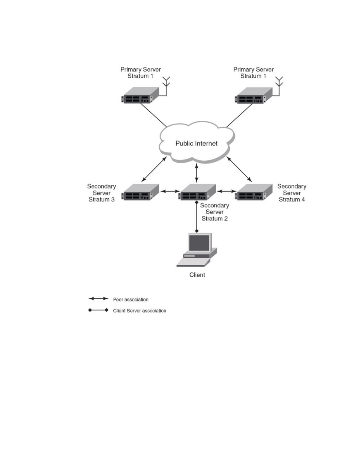
Basic Software Features
FIGURE 1 NTP Hierarchy
• NTP implementation conforms to RFC 5905.
• NTP can be enabled in server and client mode simultaneously.
• The NTP uses UDP port 123 for communicating with NTP servers/peers.
• NTP server and client can communicate using IPv4 or IPv6 address
• NTP implementation supports below association modes.
‐ Client
‐ Server
‐ Symmetric active/passive
‐ Broadcast server
‐ Broadcast client
• NTP supports maximum of 8 servers and 8 peers. The 8 peers includes statically configured and
dynamically learned.
38 FastIron Ethernet Switch Administration Guide
53-1003075-02
Page 39

Limitations
• NTP can operate in authenticate or non-authenticate mode. Only symmetric key authentication is
supported.
• By default, NTP operates in default VLAN and it can be changed.
Limitations
• FastIron devices cannot operate as primary time server (or stratum 1). It only serves as secondary
time server (stratum 2 to 15).
• NTP server and client cannot communicate using hostnames.
• NTP is not supported on VRF enabled interface or ve.
• Autokey public key authentication is not supported.
• The NTP version 4 Extension fields are not supported. The packets containing the extension fields
are discarded.
• The NTP packets having control (6) or private (7) packet mode is not supported. NTP packets with
control and private modes will be discarded.
• On reboot or switchover, all the NTP state information will be lost and time synchronization will start
fresh.
• NTP multicast server/client and manycast functionalities are not supported.
• NTP versions 1 and 2 are not supported.
• NTP MIB is not supported.
NTP and SNTP
FastIron 07.3.00c and earlier releases implements SNTP for time synchronization. In FastIron 07.3.00d,
NTP can be used for time synchronization in FCX devices with router images. From FastIron 8.0
release onwards, NTP can be used for time synchronization in all FastIron devices with both router and
switch images.
NTP and SNTP implementations cannot operate at the same time and one of them has to be disabled.
On downgrading from FastIron 07.3.00d to FastIron 07.3.00c or lower version, the entire NTP
configuration is lost.
NTP server
A NTP server will provide the correct network time on your device using the Network time protocol
(NTP). Network Time Protocol can be used to synchronize the time on devices across a network. A
NTP time server is used to obtain the correct time from a time source and adjust the local time in each
connecting device.
The NTP server functionality is enabled when you use the ntp command, provided SNTP configuration
is already removed.
When the NTP server is enabled, it will start listening on the NTP port for client requests and responds
with the reference time. Its stratum number will be the upstream time server's stratum + 1. The stratum
1 NTP server is the time server which is directly attached to the authoritative time source.
The device cannot be configured as primary time server with stratum 1. It can be configured as
secondary time server with stratum 2 to 15 to serve the time using the local clock.
The NTP server is stateless and will not maintain any NTP client information.
FastIron Ethernet Switch Administration Guide 39
53-1003075-02
Page 40

System as an Authoritative NTP Server
System as an Authoritative NTP Server
The NTP server can operate in master mode to serve time using the local clock, when it has lost
synchronization. Serving local clock can be enabled using the master command. In this mode, the
NTP server stratum number is set to the configured stratum number. When the master command is
configured and the device was never synchronized with an upstream time server and the clock setting
is invalid, the server will respond to client's request with the stratum number set to 16. While the
device is operating in the master mode and serving the local clock as the reference time, if
synchronization with the upstream server takes place it will calibrate the local clock using the NTP
time. The stratum number will switch to that of the synchronized source +1. And when synchronization
is lost, the device switches back to local clock time with stratum number as specified manually (or the
default).
NOTE
Local time and time zone has to be configured before configuring the master command.
• The following scenarios are observed when the master command is not configured and the NTP
upstream servers are configured:
• If the synchronization with the NTP server/peer is active, the system clock is synchronized and the
reference time is the NTP time.
• If the NTP server/peer is configured but not reachable and if the local clock is valid, the server will
respond to client's request with the stratum number set to 16.
• If there is no NTP server/peer configured and if the local clock is valid, the server will respond to
client's request with the stratum number set to 16.
• If there is no NTP server/peer configured and if the local clock is invalid, the system clock is not
synchronized.
The following scenarios are observed when the master command is configured and the NTP upstream
servers are also configured:
• If the synchronization with the time server/peer is active, system clock is synchronized and the
reference time is the NTP time.If the NTP server/peer is configured but not reachable, the system
clock is synchronized. If the local time is valid then the reference time is the local clock time.
• If the NTP server/peer is not configured, the system clock is synchronized. If the local clock is valid,
then the reference time is the local clock time.
• If the NTP server/peer is not configured and the local clock is invalid, system clock is not
synchronized.
NOTE
Use the master command with caution. It is very easy to override valid time sources using this
command, especially if a low stratum number is configured. Configuring multiple machines in the same
network with the master command can cause instability in timekeeping if the machines do not agree
on the time.
NTP Client
An NTP client gets time responses from an NTP server or servers, and uses the information to
calibrate its clock. This consists of the client determining how far its clock is off and adjusting its time
to match that of the server. The maximum error is determined based on the round-trip time for the
packet to be received.
The NTP client can be enabled when we enter the ntp command and configure one or more NTP
servers/peers.
40 FastIron Ethernet Switch Administration Guide
53-1003075-02
Page 41

NTP peer
The NTP client maintains the server and peer state information as association. The server and peer
association is mobilized at the startup or whenever user configures. The statically configured server/
peer associations are not demobilized unless user removes the configuration. The symmetric passive
association is mobilized upon arrival of NTP packet from peer which is not statically configured. The
associations will be demobilized on error or time-out.
NTP peer
NTP peer mode is intended for configurations where a group of devices operate as mutual backups for
each other. If one of the devices loses a reference source, the time values can flow from the surviving
peers to all the others. Each device operates with one or more primary reference sources, such as a
radio clock, or a subset of reliable NTP secondary servers. When one of the devices lose all reference
sources or simply cease operation, the other peers automatically reconfigures so that time values can
flow from the surviving peers to others.
When the NTP server or peer is configured with burst mode, client will send burst of up to 8 NTP
packets in each polling interval. The burst number of packets in each interval increases as the polling
interval increases from minimum polling interval towards maximum interval.
The NTP peer can operate in:
• Symmetric Active-When the peer is configured using the peer command.
• Symmetric Passive-Dynamically learned upon arrival of a NTP packet from the peer which is not
configured. The symmetric passive association is removed on timeout or error.
The following scenarios are observed when the upstream server is not reachable after retries:
• If the NTP server/peer is configured and the master command is not configured, then the system
clock is synchronized. When the system clock is synchronized, the server will respond to client's
request with the stratum number set to +1. And when the system clock is unsynchronized, the server
will respond to client's request with the stratum number set to 16.
• If the NTP server/peer is configured and the master command is configured, then the system clock is
synchronized. When the system clock is synchronized, the reference time is the local clock time. If
the local clock is valid then the server will respond to client's request with the specified stratum
number if it is configured otherwise with the default stratum number.
The following scenarios are observed when you remove the last NTP server/peer under the conditions the NTP server/peer is configured, master command is not configured, system clock is synchronized
and the reference time is the NTP time:
• If the local clock is not valid, the system clock is not synchronized.
• If the local clock is valid, the system clock is synchronized and the reference time is the local clock.
The server will respond to the client's request with the specified stratum number if it is configured
otherwise with the default stratum number.
NOTE
To create a symmetric active association when a passive association is already formed, disable NTP,
configure peer association and then enable NTP again.
NTP broadcast server
An NTP server can also operate in a broadcast mode. Broadcast servers send periodic time updates to
a broadcast address, while multicast servers send periodic updates to a multicast address. Using
broadcast packets can greatly reduce the NTP traffic on a network, especially for a network with many
NTP clients.
The interfaces should be enabled with NTP broadcasting. The NTP broadcast server broadcasts the
FastIron Ethernet Switch Administration Guide 41
53-1003075-02
Page 42

NTP broadcast client
NTP packets periodically (every 64 sec) to subnet broadcast IP address of the configured interface.
• NTP broadcast packets are sent to the configured subnet when the NTP broadcast server is
configured on the interface which is up and the IP address is configured for the broadcast subnet
under the following conditions:
‐ The local clock is valid and the system clock is synchronized
‐ The local clock is valid and the system clock is not synchronized
‐ Authentication key is configured, the system clock is synchronized and the local clock is
valid
• NTP broadcast packets are not sent in the following cases:
‐ NTP broadcast server is configured on the interface which is down even if the system
clock is synchronized and the local clock is valid.
‐ NTP broadcast server is configured on the interface which is up and no IP address is
configured for the broadcast subnet even if the system clock is synchronized and the local
clock is valid.
‐ NTP broadcast server is configured on the interface which is not present and no IP
address is configured for the broadcast subnet even if the system clock is synchronized
and the local clock is valid.
‐ NTP broadcast server without authentication key is configured on the interface which is up
and the IP address is configured for the broadcast subnet even when NTP authentication
is enforced and the system clock is synchronized and the local clock is valid.
NTP broadcast client
An NTP broadcast client listens for NTP packets on a broadcast address. When the first packet is
received, the client attempts to quantify the delay to the server, to better quantify the correct time from
later broadcasts. This is accomplished by a series of brief interchanges where the client and server act
as a regular (non-broadcast) NTP client and server. Once interchanges occur, the client has an idea of
the network delay and thereafter can estimate the time based only on broadcast packets.
NTP associations
Networking devices running NTP can be configured to operate in variety of association modes when
synchronizing time with reference time sources. A networking device can obtain time information on a
network in two ways-by polling host servers and by listening to NTP broadcasts. That is, there are two
types of associations-poll-based and broadcast-based.
NTP poll-based associations
The following modes are the NTP polling based associations:
1. Server mode
2. Client mode
3. Symmetric Active/Passive
The server mode requires no prior client configuration. The server responds to client mode NTP
packets. Use the master command to set the device to operate in server mode when it has lost the
synchronization.
When the system is operating in the client mode, it polls all configured NTP servers and peers. The
device selects a host from all the polled NTP servers to synchronize with. Because the relationship
that is established in this case is a client-host relationship, the host will not capture or use any time
information sent by the local client device. This mode is most suited for file-server and workstation
42 FastIron Ethernet Switch Administration Guide
53-1003075-02
Page 43

NTP broadcast-based associations
clients that are not required to provide any form of time synchronization to other local clients. Use the
server and peer to individually specify the time server that you want the networking device to
consider synchronizing with and to set your networking device to operate in the client mode.
Symmetric active/passive mode is intended for configurations where group devices operate as
mutual backups for each other. Each device operates with one or more primary reference sources,
such as a radio clock, or a subset of reliable NTP secondary servers. If one of the devices lose all
reference sources or simply cease operation, the other peers automatically reconfigures. This helps
the flow of time value from the surviving peers to all the others.
When a networking device is operating in the symmetric active mode, it polls its assigned timeserving hosts for the current time and it responds to polls by its hosts. Because symmetric active
mode is a peer-to-peer relationship, the host will also retain time-related information of the local
networking device that it is communicating with. When many mutually redundant servers are
interconnected via diverse network paths, the symmetric active mode should be used. Most stratum 1
and stratum 2 servers on the Internet adopt the symmetric active form of network setup. The FastIron
device operates in symmetric active mode, when the peer information is configured using the peer
command and specifying the address of the peer. The peer is also configured in symmetric active
mode in this way by specifying the FastIron device information. If the peer is not specifically
configured, a symmetric passive association is activated upon arrival of a symmetric active message.
The specific mode that you should set for each of your networking devices depends primarily on the
role that you want them to assume as a timekeeping device (server or client) and the device's
proximity to a stratum 1 timekeeping server. A networking device engages in polling when it is
operating as a client or a host in the client mode or when it is acting as a peer in the symmetric active
mode. An exceedingly large number of ongoing and simultaneous polls on a system can seriously
impact the performance of a system or slow the performance of a given network. To avoid having an
excessive number of ongoing polls on a network, you should limit the number of direct, peer-to-peer
or client-to-server associations. Instead, you should consider using NTP broadcasts to propagate
time information within a localized network.
NTP broadcast-based associations
The broadcast-based NTP associations should be used in configurations involving potentially large
client population. Broadcast-based NTP associations are also recommended for use on networks that
have limited bandwidth, system memory, or CPU resources.
The devices operating in the broadcast server mode broadcasts the NTP packets periodically which can
be picked up by the devices operating in broadcast client mode. The broadcast server is configured
using the broadcast command.
A networking device operating in the broadcast client mode does not engage in any polling. Instead, the
device receives the NTP broadcast server packets from the NTP broadcast servers in the same subnet.
The NTP broadcast client forms a temporary client association with the NTP broadcast server. A
broadcast client is configured using the broadcast client command. For broadcast client mode to work,
the broadcast server and the clients must be located on the same subnet.
FastIron Ethernet Switch Administration Guide 43
53-1003075-02
Page 44

Synchronizing time
Synchronizing time
After the system peer is chosen, the system time is synchronized based on the time difference with
system peer:
• If the time difference with the system peer is 128 msec and < 1000 sec, the system clock is stepped
to the system peer reference time and the NTP state information is cleared.
Authentication
The time kept on a machine is a critical resource, so it is highly recommended to use the encrypted
authentication mechanism.
The NTP can be configured to provide cryptographic authentication of messages with the clients/
peers, and with its upstream time server. Symmetric key scheme is supported for authentication. The
scheme uses MD5 keyed hash algorithm.
The authentication can be enabled using the authenticate command. The set of symmetric key and
key string is specified using the authentication-key command.
If authentication is enabled, NTP packets not having a valid MAC address are dropped.
If the NTP server/peer is configured without authentication keys, the NTP request is not sent to the
configured server/peer.
NOTE
The same set or subset of key id and key string should be installed on all NTP devices.
VLAN and NTP
When VLAN is configured,
• NTP time servers should be reachable through the interfaces which belong to the configured VLAN.
Otherwise, NTP packets are not transmitted. This is applicable to both the unicast and the
broadcast server/client.
• NTP broadcast packets are sent only on the interface which belongs to the configured VLAN.
• The received unicast or broadcast NTP packet are dropped if the interface on which packet has
been received does not belong to the configured VLAN
Configuring NTP
NTP services are disabled on all interfaces by default.
Prerequisites:
• Before you begin to configure NTP, you must use the clock set command to set the time on your
device to within 1000 seconds of the coordinated Universal Time (UTC).
• Disable SNTP by removing all the SNTP configurations.
44 FastIron Ethernet Switch Administration Guide
53-1003075-02
Page 45

Enabling NTP
Enabling NTP
NTP and SNTP implementations cannot operate simultaneously. By default, SNTP is enabled. To
disable SNTP and enable NTP, use the ntp command in configuration mode. This command enables
the NTP client and server mode if SNTP is disabled.
Brocade(config)# ntp
Brocade(config-ntp)#
Syntax: [no] ntp
Use the no form of the command to disable NTP and remove the NTP configuration.
NOTE
The no ntp command removes all the configuration which are configured statistically and learned
associations from NTP neighbors.
NOTE
You cannot configure the ntp command if SNTP is enabled. If SNTP is enabled, configuring the ntp
command will display the following message:"SNTP is enabled. Disable SNTP before using NTP for
time synchronization"
Disabling NTP
To disable the NTP server and client mode, use the disable command in NTP configuration mode.
Disabling the NTP server or client mode will not remove the configurations.
Brocade(config-ntp)# disable
Syntax: [no] disable [ serve ]
If the serve keyword is specified, then NTP will not serve the time to downstream devices. The serve
keyword disables the NTP server mode functionalities. If the serve keyword is not specified, then both
NTP client mode and NTP server mode functionalities are disabled.
Use the no form of the command to enable NTP client and server mode. To enable the client mode, use
the no disable command. To enable the client and server mode, use the no disable serve command.
The no disable command enables both client and server, if the client is already enabled and server is
disabled at that time "no disable server " enables the server.
NOTE
The disable command disables the NTP server and client mode; it does not remove the NTP
configuration.
Enabling NTP authentication
To enable Network Time Protocol (NTP) strict authentication, use the authenticate command. To
disable the function, use the no form of this command.
By default, authentication is disabled.
Brocade(config-ntp)# [no] authenticate
Syntax: [no] authenticate
FastIron Ethernet Switch Administration Guide 45
53-1003075-02
Page 46

Defining an authentication key
Defining an authentication key
To define an authentication key for Network Time Protocol (NTP), use the authentication-key
command. To remove the authentication key for NTP, use the no form of this command.
By default, authentication keys are not configured.
Brocade(config-ntp)# authentication-key key-id 1 md5 moof
Syntax: [no] authentication-key key-id md5 key-string
The valid key-id parameter is 1 to 65535.
MD5 is the message authentication support that is provided using the Message Digest 5 Algorithm.
The key type md5 is currently the only key type supported.
The key-string option is the value of the MD5 key. The maximum length of the key string may be
defined up to 16 characters. Up to 32 keys may be defined.
Specifying a source interface
When the system sends an NTP packet, the source IP address is normally set to the address of the
interface through which the NTP packet is sent. Use the source-interface command to configure a
specific interface from which the IP source address will be taken. To remove the specified source
address, use the no form of this command.
This interface will be used for the source address for all packets sent to all destinations. If a source
address is to be used for a specific association, use the source keyword in the peer or server
command.
NOTE
If the source-interface is not configured, then the lowest IP address in the outgoing interface will be
used in the NTP packets. Source IP address of a tunnel interface is not supported.
Brocade(config-ntp)# source-interface ethernet 1/3/1
Syntax: [no] source-interface ethernet { port | loopback num | ve num }
Specify the port parameter in the format stack-unit/slotnum/portnum.
The loopback num parameter specifies the loopback interface number.
The ve num parameter specifies the virtual port number.
Enable or disable the VLAN containment for NTP
To enable or disable the VLAN containment for NTP, use the access-control vlan command. To
remove the specified NTP VLAN configuration, use the no form of this command.
NOTE
The management interface is not part of any VLAN. When configuring the VLAN containment for NTP,
it will not use the management interface to send or receive the NTP packets.
Brocade(config-ntp)# access-control vlan 100
Syntax: [no] access-control vlan vlan-id
46 FastIron Ethernet Switch Administration Guide
53-1003075-02
Page 47

Configuring the NTP client
The vlan-id parameter specifies the VLAN ID number.
Configuring the NTP client
To configure the device in client mode and specify the NTP servers to synchronize the system clock,
use the server command. A maximum 8 NTP servers can be configured. To remove the NTP server
configuration, use the no form of this command.
By default, no servers are configured.
Brocade(config-ntp)#server 1.2.3.4 key 1234
Syntax: [no] server { ipv4-address | ipv6-address } [ version num ] [ key key-id ] [ minpoll interval ] [
maxpoll interval ] [ burst ]
The ipv4-address or ipv6-address parameter is the IP address of the server providing the clock
synchronization.
The version num option defines the Network Time Protocol (NTP) version number. Valid values are 3 or
4. If the num option is not specified, the default is 4.
The key key-id option defines the authentication key. By default, no authentication key is configured.
The minpoll interval option is the shortest polling interval. The range is from 4 through 17. Default is 6.
The interval argument is power of 2 (4=16s, 5=32s, 6=64s, 7=128s, 8=256s, 9=512s, and so on).
The maxpoll interval option is the longest polling interval. The range is 4 through 17. Default is 10. The
interval argument is calculated by the power of 2 (4=16s, 5=32s, 6=64s, 7=128s, 8=256s, 9=512s, and
so on).
The burst option sends a burst of packets to the server at each polling interval.
Configuring the master
To configure the FastIron device as a Network Time Protocol (NTP) master clock to which peers
synchronize themselves when an external NTP source is not available, use the master command. The
master clock is disabled by default. To disable the master clock function, use the no form of this
command.
NOTE
This command is not effective, if the NTP is enabled in client-only mode.
Brocade(config-ntp)# master stratum 5
Syntax: [no] master [ stratum number ]
The number variable is a number from 2 to 15. It indicates the NTP stratum number that the system will
claim.
Configuring the NTP peer
To configure the software clock to synchronize a peer or to be synchronized by a peer, use the peer
command. A maximum of 8 NTP peers can be configured. To disable this capability, use the no form of
this command.
This peer command is not effective if the NTP is enabled in client-only mode.
FastIron Ethernet Switch Administration Guide 47
53-1003075-02
Page 48

Configuring NTP on an interface
NOTE
If the peer is a member of symmetric passive association, then configuring the peer command will fail.
Brocade(config-ntp)# peer 1.2.3.4 key 1234
Syntax: [no] peer { ipv4-address | ipv6-address } [ version num [ key key-id ] [ minpoll interval ] [
maxpoll interval ] [ burst ]
The ipv4-address or ipv6-address parameter is the IP address of the peer providing the clock
synchronization.
The version num option defines the Network Time Protocol (NTP) version number. Valid values are 3
and 4. If this option is not specified, then the default is 4.
The key key-id option defines the authentication key. By default, no authentication key is configured.
The minpoll interval option is the shortest polling interval. The range is from 4 through 17. Default is 6.
The interval argument is power of 2 (4=16s, 5=32s, 6=64s, 7=128s, 8=256s, 9=512s, and so on).
The maxpoll interval option is the longest polling interval. The range is 4 through 17. Default is 10. The
interval argument is calculated by the power of 2 (4=16s, 5=32s, 6=64s, 7=128s, 8=256s, 9=512s, and
so on).
The burst option sends a burst of packets to the peer at each polling interval.
NOTE
When the NTP server/peer is configured, the master command is not configured; on configuring the
clock set command the system clock is not synchronized. When the master command is configured,
on configuring the clock set command the system clock is synchronized and the reference time will be
the local clock.
To have active peers at both the ends, you need to disable NTP, configure the peers and enable the
NTP using the no disable command.
Configuring NTP on an interface
To configure the NTP interface context, use the ntp-interface command. The broadcast server or
client is configured on selected interfaces. To remove the NTP broadcast configurations on the
specified interface, use the no form of this command.
NOTE
The ntp-interface command is a mode change command, and will not be included in to the show run
output unless there is configuration below that interface.
Brocade(config-ntp)# ntp-interface ethernet 2/13
Brocade(config-ntp-if-e1000-2/13)# exit
Brocade(config-ntp)# ntp-interface management 1
Brocade(config-ntp-mgmt-1)# exit
Brocade(config-ntp)# ntp-interface ve 100
Brocade(config-ntp-ve-100)#
Syntax: [no] ntp-interface { management 1 | ethernet port | ve id }
The management 1 parameter is the management port 1.
The ethernet port parameter specifies the ethernet port number. Specify the port parameter in the
format stack-unit/slotnum/portnum.
48 FastIron Ethernet Switch Administration Guide
53-1003075-02
Page 49

Configuring the broadcast client
The ve id parameter specifies the virtual port number.
Configuring the broadcast client
To configure a device to receive Network Time Protocol (NTP) broadcast messages on a specified
interface, use the broadcast client command. NTP broadcast client can be enabled on maximum of 16
ethernet interfaces. If the interface is operationally down or NTP is disabled, then the NTP broadcast
server packets are not received. To disable this capability, use the no form of this command.
Brocade(config-ntp mgmt-1)# broadcast client
Syntax: [no] broadcast client
Configuring the broadcast destination
To configure the options for broadcasting Network Time Protocol (NTP) traffic, use the ntp broadcast
destination command. The NTP broadcast server can be enabled on maximum 16 ethernet interfaces
and four subnet addresses per interface. If the interface is operationally down or there is no ip address
configured for the subnet address, then the NTP broadcast server packets are not sent. To disable this
capability, use the no form of this command.
By default, the broadcast mode is not enabled.
NOTE
This command is not effective, if the NTP server is disabled.
Brocade(config)#int m1
Brocade(config-if-mgmt-1)#ip address 10.20.99.173/24
Brocade(config-if-mgmt-1)#ntp
Brocade(config-ntp)#ntp-interface m1
Brocade(config-ntp -mgmt-1)# broadcast destination 10.20.99.0 key 2
Syntax: [no] broadcast destination ip-address [ key key-id ] [ version num ]
The ip-address parameter is the IPv4 subnet address of the device to send NTP broadcast messages
to.
The key key-id option defines the authentication key. By default, no authentication key is configured.
The version num option defines the Network Time Protocol (NTP) version number. If this option is not
specified, then the default value is 4.
Displaying NTP status
Use the show ntp status command to display the NTP status.
Brocade#show ntp status
Clock is synchronized, stratum 4, reference clock is 10.20.99.174
precision is 2**-16
reference time is D281713A.80000000 (03:21:29.3653007907 GMT+00 Thu Dec 01 2011)
clock offset is -2.3307 msec, root delay is 24.6646 msec
root dispersion is 130.3376 msec, peer dispersion is 84.3335 msec
system poll interval is 64, last clock update was 26 sec ago
NTP server mode is enabled, NTP client mode is enabled
NTP master mode is disabled, NTP master stratum is 8
NTP is not in panic mode
Displaying NTP status show ntp status command output descriptions
FastIron Ethernet Switch Administration Guide 49
53-1003075-02
Page 50

Displaying NTP associations
Field Description
synchronized Indicates the system clock is synchronized to NTP server or peer.
stratum Indicates the stratum number that this system is operating. Range 2..15.
NTP status command output descriptionsTABLE 4
reference IPv4 address or first 32 bits of the MD5 hash of the IPv6 address of the peer to which clock
precision Precision of the clock of this system in Hz.
reference time Reference time stamp.
clock offset Offset of clock (in milliseconds) to synchronized peer.
root delay Total delay (in milliseconds) along path to root clock.
root dispersion Dispersion of root path.
peer dispersion Dispersion of root path.
system poll interval Poll interval of the local system.
last update Time the router last updated its NTP information.
server mode Status of the NTP server mode for this device.
client mode Status of the NTP client mode for this device.
master Status of the master mode.
master stratum Stratum number that will be used by this device when master is enabled and no upstream
is synchronized.
time servers are accessible.
panic mode Status of the panic mode.
Displaying NTP associations
Use the show ntp associations command to display detailed association information of the NTP
server or peers.
Brocade# show ntp associations
address ref clock st when poll reach delay offset disp
*~172.19.69.1 172.24.114.33 3 25 64 3 2.89 0.234 39377
~2001:235::234
INIT 16 - 64 0 0.00 0.000 15937
* synced, # selected, + candidate, - outlayer, x falseticker, ~ configured
Displaying NTP associations show ntp associations command output descriptions
50 FastIron Ethernet Switch Administration Guide
53-1003075-02
Page 51

Displaying NTP associations details
NTP associations command output descriptionsTABLE 5
Field Description
* The peer has been declared the system peer and lends its variables to the system variables.
# This peer is a survivor in the selection algorithm.
+ This peer is a candidate in the combine algorithm.
- This peer is discarded as outlier in the clustering algorithm.
x This peer is discarded as 'falseticker' in the selection algorithm.
~ The server or peer is statically configured.
address IPv4 or IPv6 address of the peer.
ref clock IPv4 address or first 32 bits of the MD5 hash of the IPv6 address of the peer to which clock is
St Stratum setting for the peer.
when Time, in seconds, since last NTP packet was received from peer.
poll Polling interval (seconds).
reach Peer reachability (bit string, in octal).
delay Round-trip delay to peer, in milliseconds.
offset Relative time difference between a peer clock and a local clock, in milliseconds.
disp Dispersion.
synchronized.
Displaying NTP associations details
Use the show ntp associations detail command to display all the NTP servers and peers association
information.
Brocade# show ntp association detail
2001:1:99:30::1 configured server, sys peer, stratum 3
ref ID 204.235.61.9, time d288dc3b.f2a17891 (10:23:55.4070668433 Pacific Tue Dec 06
2011)
our mode client, peer mode server, our poll intvl 10, peer poll intvl 10,
root delay 0.08551025 msec, root disp 0.09309387, reach 17, root dist 0.17668502
delay 0.69961487 msec, offset -13.49459670 msec, dispersion 17.31550718,
precision 2**-16, version 4
org time d288df70.a91de561 (10:37:36.2837308769 Pacific Tue Dec 06 2011)
rcv time d288df70.a0c8d19e (10:37:36.2697515422 Pacific Tue Dec 06 2011)
xmt time d288df70.a086e4de (10:37:36.2693194974 Pacific Tue Dec 06 2011)
filter delay 1.7736 0.9933 0.8873 0.6699 0.7709 0.7712 0.7734 6.7741
filter offset -17.9936 33.0014 -13.6604 -13.4494 -14.4481 -16.4453 -18.4423 -22.0025
filter disp 15.6660 0.0030 17.7730 17.7700 17.6670 17.6640 17.6610 16.6635
filter epoch 55824 56866 55686 55688 55690 55692 55694 55759
FastIron Ethernet Switch Administration Guide 51
53-1003075-02
Page 52

Basic Software Features
Use the show ntp associations detail command with the appropriate parameters to display the NTP
servers and peers association information for a specific IP address.
Brocade# show ntp association detail 1.99.40.1
1.99.40.1 configured server, candidate, stratum 3
ref ID 216.45.57.38, time d288de7d.690ca5c7 (10:33:33.1762436551 Pacific Tue Dec 06
2011)
our mode client, peer mode server, our poll intvl 10, peer poll intvl 10,
root delay 0.02618408 msec, root disp 0.10108947, reach 3, root dist 0.23610585
delay 0.92163588 msec, offset 60.77749188 msec, dispersion 70.33842156,
precision 2**-16, version 4
org time d288defa.b260a71f (10:35:38.2992678687 Pacific Tue Dec 06 2011)
rcv time d288defa.a2efbd41 (10:35:38.2733620545 Pacific Tue Dec 06 2011)
xmt time d288defa.a2ae54f8 (10:35:38.2729334008 Pacific Tue Dec 06 2011)
filter delay 0.000 6.7770 6.7773 6.7711 6.7720 6.7736 6.7700 0.9921
filter offset 0.000 19.0047 19.1145 19.2245 19.3313 17.4410 15.4463 60.7777
filter disp 16000.000 16.0005 15.9975 15.9945 15.9915 15.8885 15.8855 0.0030
filter epoch 55683 55683 55685 55687 55689 55691 55693 56748
Syntax: show ntp association detail { ipv4-address | ipv6-address }
Displaying NTP associations on page 50 show ntp associations detail command output descriptions
NTP associations detail command output descriptionsTABLE 6
Field Description
server Indicates server is statically configured.
symmetric active peer Indicates peer is statically configured.
symmetric passive peer Indicates peer is dynamically configured.
sys_peer This peer is the system peer
candidate This peer is chosen as candidate in the combine algorithm.
reject This peer is rejected by the selection algorithm
falsetick This peer is dropped as falseticker by the selection algorithm
outlyer This peer is dropped as outlyer by the clustering algorithm
Stratum Stratum number
ref ID IPv4 address or hash of IPv6 address of the upstream time server to which the peer is
synchronized.
Time Last time stamp that the peer received from its master.
our mode This system's mode relative to peer (active/passive/client/server/bdcast/bdcast client).
peer mode Mode of peer relative to this system.
our poll intvl This system's poll interval to this peer.
peer poll intvl Poll interval of peer to this system
52 FastIron Ethernet Switch Administration Guide
53-1003075-02
Page 53

NTP associations detail command output descriptions (Continued)TABLE 6
Field Description
root delay The delay along path to root (the final stratum 1 time source).
root disp Dispersion of path to root.
reach peer The peer reachability (bit string in octal).
Delay Round-trip delay to peer.
offset Offset of a peer clock relative to this clock.
Dispersion Dispersion of a peer clock.
precision Precision of a peer clock.
version Peer NTP version number.
Configuration Examples
org time Originate time stamp of the last packet.
rcv time Receive time stamp of the last packet.
xmt time Transmit time stamp of the last packet.
filter delay Round-trip delay in milliseconds of last 8 samples.
filter offset Clock offset in milliseconds of last 8 samples.
filter error Approximate error of last 8 samples.
Configuration Examples
The following sections list configuration examples to configure the Brocade device.
NTP server and client mode configuration
Sample CLI commands to configure the Brocade device in NTP server and client modes.
Brocade(config-ntp)# server 10.1.2.3 minpoll 5 maxpoll 10
Brocade(config-ntp)# server 11::1/64
Brocade(config-ntp)# peer 10.100.12.18
Brocade(config-ntp)# peer 10.100.12.20
Brocade(config-ntp)# peer 10.100.12.67
Brocade(config-ntp)# peer 10.100.12.83
NTP client mode configuration
Sample CLI commands to configure the Brocade device in NTP client mode.
Brocade(config-ntp)# server 10.1.2.3 minpoll 5 maxpoll 10
Brocade(config-ntp)# server 11::1/24
FastIron Ethernet Switch Administration Guide 53
53-1003075-02
Page 54

NTP strict authentication configuration
Brocade(config-ntp)# peer 10.100.12.83
Brocade(config-ntp)# disable serve
NTP strict authentication configuration
Sample CLI commands to configure the Brocade device in strict authentication mode.
Brocade(config-ntp)# authenticate
Brocade(config-ntp)# authentication-key key-id 1 md5 key123
Brocade(config-ntp)# server 10.1.2.4 key 1
NTP loose authentication configuration
Sample CLI commands to configure the Brocade device in loose authentication mode. This allows
some of the servers or clients to use the authentication keys.
Brocade(config-ntp)# authentication-key key-id 1 md5 key123
Brocade(config-ntp)# server 10.1.2.4 key 1
Brocade(config-ntp)# server 10.1.2.7
NTP interface context for the broadcast server or client mode
Sample CLI commands to enter the NTP interface context.
Brocade(config)#int management 1
Brocade(config-if-mgmt-1)#ip address 10.20.99.173/24
Brocade(config-if-mgmt-1)#ntp
Brocade(config-ntp)# ntp-interface management 1
Brocade(config-ntp-mgmt-1)# broadcast destination 10.23.45.128
Brocade(config-ntp)# ntp-interface ethernet 1/3
Brocade(config-ntp-if-e1000-1/3)# broadcast destination 10.1.1.0 key 1
Brocade(config-ntp)# ntp-interface ve 100
Brocade(config-ntp-ve-100)# broadcast destination 10.2.2.0 key 23
NTP broadcast client configuration
Sample CLI commands to configure the NTP broadcast client.
Brocade(config-ntp)# ntp-interface management 1
Brocade(config-ntp-mgmt-1)# broadcast client
Brocade(config-ntp)# ntp-interface ethernet 1/5
Brocade(config-ntp-if-e1000-1/5)# broadcast client
Brocade(config-ntp)# ntp-interface ve 100
Brocade(config-ntp-ve-100)# broadcast client
Basic port parameter configuration
The procedures in this section describe how to configure the port parameters shown in Basic Software
Features on page 29.
All Brocade ports are pre-configured with default values that allow the device to be fully operational at
initial startup without any additional configuration. However, in some cases, changes to the port
parameters may be necessary to adjust to attached devices or other network requirements.
54 FastIron Ethernet Switch Administration Guide
53-1003075-02
Page 55

Specifying a port address
Specifying a port address
You can specify a port address for an uplink (data) port, stacking port, or a management port.
ICX 6430 and ICX 6450
Specifying a data port
The port address format is is stack unit/slot/port, where:
• stack unit --Specifies the stack unit ID. For the ICX 6430, range is from 1 to 4. For the ICX 6450,
range is from 1 to 8. If the device is not part of a stack, the stack unit ID is 1.
• slot --Specifies the slot number. Can be 1 or 2.
• port --Specifies the port number in the slot. Range is from 1 to 24 (24-port models) or 1 to 48 (48-port
models).
This example shows how to specify port 2 in slot 1 of a device that is not part of a stack:
Brocade (config) # interface ethernet 1/1/2
Specifying a stacking port
The port address format is is stack unit/slot/port, where:
• stack unit --Specifies the stack unit ID. For the ICX 6430, range is from 1 to 4. For the ICX 6450,
range is from 1 to 8.
• slot --Specifies the slot number. Stacking ports are in slot 2.
• port --Specifies the port number in the slot. Stacking ports are 1, 2, 3, and 4.
This example shows how to specify stacking port 3 in slot 2 of unit 3 in a stack:
Brocade (config) # interface ethernet 3/2/3
Specifying a management port
The management port number is always 1. This example shows how to specify the management port:
Brocade (config) # interface management 1
ICX 6610
Specifying a data port
The port address format is is stack unit/slot/port, where:
• stack unit --Specifies the stack unit ID. Range is from 1 to 8. If the device is not part of a stack, the
stack unit ID is 1.
• slot --Specifies the slot number. Can be 1 or 3.
• port --Specifies the port number in the slot. Range is from 1 to 24 (24-port models) or 1 to 48 (48-port
models).
This example shows how to specify port 2 in slot 1 of a device that is not part of a stack:
Brocade (config) # interface ethernet 1/1/2
FastIron Ethernet Switch Administration Guide 55
53-1003075-02
Page 56

FCX
Specifying a stacking port
The port address format is is stack unit/slot/port, where:
• stack unit --Specifies the stack unit ID. Range is from 1 to 8.
• slot --Specifies the slot number. Stacking ports are in slot 2.
• port --Specifies the port number in the slot. Dedicated stacking ports are 1, 2, 6, and 7.
This example shows how to specify stacking port 2 in slot 2 of unit 3 in a stack:
Brocade (config) # interface ethernet 3/2/2
Specifying a management port
The management port number is always 1. This example shows how to specify the management port:
Brocade (config) # interface management 1
FCX
Specifying a data port
The port address format is stack unit/slot/port, where:
• stack unit --Specifies the stack unit ID. Range is from 1 to 8. If the device is not part of a stack, the
stack unit ID is 1.
• slot --Specifies the slot number. Can be 1 or 3.
• port --Specifies the port number in the slot. Range is from 1 to 24 (24-port models) or 1 to 48 (48port models).
This example shows how to specify port 2 in slot 1 of a device that is not part of a stack:
Brocade (config) # interface ethernet 1/1/2
Specifying a stacking port
The port address format is stack unit/slot/port, where:
• stack unit --Specifies the stack unit ID. Range is from 1 to 8.
• slot --Specifies the slot number. Default stacking ports are in slot 2 (FCX S/S-F) and slot3 (FCX E/I).
• port --Specifies the port number in the slot. Default stacking ports in slot 2 and slot 3 are ports 1 and
2.
This example shows how to specify port 2 in slot 2 of unit 3 in a stack:
Brocade (config) # interface ethernet 3/2/2
Specifying a management port
The management port number is always 1. This example shows how to specify the management port:
Brocade (config) # interface management 1
56 FastIron Ethernet Switch Administration Guide
53-1003075-02
Page 57

FSX
FSX
Specifying a data port
The port address format is slot/port, where:
• slot --Specifies the interface slot number. Range is from 1 to 8 (FSX 800) or 1 to 16 (FSX 1600).
• port --Specifies the port number in the slot. Range is from 1 to 48 depending on the interface module.
This example shows how to specify port 2 in slot 1:
Brocade (config) # interface ethernet 1/2
Specifying a management port
The management port number is always 1. This example shows how to specify the management port:
Brocade (config) # interface management 1
NOTE
Stacking is not supported on FSX devices.
Assigning port names
You can assign text strings as port names, which help you identify ports with meaningful names. You
can assign port names to individual ports or to a group of ports. You can assign a port name to physical
ports, virtual interfaces, and loopback interfaces.
Assigning a port name
To assign a name to a port, enter commands such as the following:
device(config)# interface ethernet 2
device(config-if-e1000-2)# port-name Marsha
Syntax: port-name text
The text parameter is an alphanumeric string. The name can be up to 255 characters long. The name
can contain blanks. You do not need to use quotation marks around the string, even when it contains
blanks. The port name can contain special characers as well, but the percentage character (%), if it
appears at the end of the port name, is dropped.
Assigning the same name to multiple ports
To assign a name to a range of ports, enter commands such as the following:
Brocade (config)# interface ethernet 1/1/1 to 1/1/10
Brocade (config-mif-1/1/1-1/1/10)# port-name connected-to-the nearest device
Syntax: [no] port-name text
To remove the assigned port name, use no form of the command.
The text parameter is an alphanumeric string, up to 255 characters long. The name can contain blanks.
You do not need to use quotation marks around the string, even when it contains blanks.
FastIron Ethernet Switch Administration Guide 57
53-1003075-02
Page 58

Displaying the port name for an interface
You can also specify the individual ports, separated by space.
To assign a name to multiple specific ports, enter commands such as the following:
Brocade (config)# interface ethernet 1/1/1 ethernet 1/1/5 ethernet 1/1/7
Brocade (config-mif-1/1/1, 1/1/5, 1/1/7)# port-name connected-to-the nearest device
Displaying the port name for an interface
You can use the show interface brief command to display the name assigned to the port. If any of
the ports have long port names, they are truncated. To show full port names, use the show interfaces
brief wide command.
Brocade# show interfaces brief
Port Link State Dupl Speed Trunk Tag Pvid Pri
MAC
Name
1/1/23 Up Forward Full 1G None No 1 0 748e.f82d.7a16 connected1/1/47 Up Forward Full 1G None No 1 0 748e.f82d.7a2e
mgmt1 Up None Full 1G None No None 0 748e.f82d.7a00
In this output, the port name for inteface 1/1/23 is truncated.
Use the show interface brief wide command to avoid truncating long port names.
To display the complete port name for an interface, enter the following command.
Brocade# show interface brief wide
Port Link State Dupl Speed Trunk Tag Pvid Pri
MAC
Name
1/1/23 Up Forward Full 1G None No 1 0 748e.f82d.7a16 connectedto-the nearest device
1/1/47 Up Forward Full 1G None No 1 0 748e.f82d.7a2e
mgmt1 Up None Full 1G None No None 0 748e.f82d.7a00
Syntax: show interface brief [ wide ] [ ethernet stack-unit/slot/port | loopback port | management
port | slot port | tunnel port | ve port ]
The ethernet stack-unit/slot/port parameter specifies the Ethernet port for which you want to display
the interface information.
The loopback option specifies the loopback port for which you want to display the interface
information.
The management option specifies the management port for which you want to display the interface
information.
The slot option specifies all the ports in a slot for which you want to display the interface information.
The tunnel option specifies the tunnel port for which you want to display the interface information.
The ve option specifies the virtual routing (VE) port for which you want to display the interface
information.
Displaying the port name for an interface describes the output parameters of the show interface brief
wide command.
Output parameters of the show interface brief wide commandTABLE 7
Field Description
Port Specifies the port number.
58 FastIron Ethernet Switch Administration Guide
53-1003075-02
Page 59

Port speed and duplex mode modification
Output parameters of the show interface brief wide command (Continued)TABLE 7
Field Description
Link Specifies the link state.
Port-State Specifies the current port state.
Speed Specifies the link speed.
Tag Specifies if the port is tagged or not.
Pvid Specifies the port VLAN ID.
Pri Specifies the priority.
MAC Specifies the MAC address.
Name Specifies the port name.
To display the complete port name for an Ethernet interface, enter a command such as the following.
Brocade# show interface brief wide ethernet 1/1/23
PPort Link State Dupl Speed Trunk Tag Pvid Pri MAC Name
1/1/23 Up Forward Full 1G None No 1 0 748e.f82d.7a16
connected- to-FCX
Syntax: show interface brief wide ethernet stack-unit/slot/port
For more information about field descriptions of the command output, refer Displaying the port name for
an interface.
Port speed and duplex mode modification
The Gigabit Ethernet copper ports are designed to auto-sense and auto-negotiate the speed and duplex
mode of the connected device. If the attached device does not support this operation, you can manually
enter the port speed to operate at either 10, 100, or 1000 Mbps. This configuration is referred to as
force mode. The default and recommended setting is 10/100/1000 auto-sense. Port duplex mode and
port speed are modified by the same command
NOTE
You can modify the port speed of copper ports only; this feature does not apply to fiber ports.
NOTE
For optimal link operation, copper ports on devices that do not support 803.3u must be configured with
like parameters, such as speed (10,100,1000), duplex (half, full), MDI/MDIX, and Flow Control.
FastIron Ethernet Switch Administration Guide 59
53-1003075-02
Page 60

Port speed and duplex mode configuration syntax
Port speed and duplex mode configuration syntax
The following commands change the port speed of copper interface 8 on a FastIron device from the
default of 10/100/1000 auto-sense, to 100 Mbps operating in full-duplex mode.
device(config)# interface ethernet 8
device(config-if-e1000-8)# speed-duplex 100-full
Syntax: speed-duplex value
The value variable can be one of the following values:
• 10-full - 10 Mbps, full duplex
• 10-half - 10 Mbps, half duplex
• 100-full - 100 Mbps, full duplex
• 100-half - 100 Mbps, half duplex
• 1000-full-master - 1 Gbps, full duplex master
• 1000-full-slave - 1 Gbps, full duplex slave
• auto - auto-negotiation
The default is auto (auto-negotiation).
Use the no form of the command to restore the default.
NOTE
On FastIron devices, when setting the speed and duplex-mode of an interface to 1000-full, configure
one side of the link as master (1000-full-master) and the other side as slave (1000-full-slave).
NOTE
On Brocade ICX 6610 and ICX 6650 devices, after you remove the 10 Gbps speed from the running
configuration, plugging in a 1Gbps optic SFP transceiver into a 10 Gbps port causes the software to
fail to revert the ports back from the default 10Gbps mode to the 1 Gbps speed. Remove the 1Gbps
SFP transceiver and plug in the 10Gbps optic SFP+transceiver so that the devices go into the default
10 Gbps mode.
NOTE
When you use fixed speed and duplex configuration, you should use the non-auto MDI-MDIX
configuration.
Configuration considerations for port speed and duplex mode
The following considerations apply to the port speed and duplex mode configuration:
• When a local partner issues a speed-duplex 100-full or speed-duplex 10-full command, if the
remote partner does not issue the same commands, it becomes 100-half or 10-half, and may
receive collision errors. The local partner may receive In Errors such as CRC, fragments, or bad
packets.
• When a local partner issues a speed-duplex 100-full or speed-duplex 10-full command, if the
remote partner issues the same command, the port may or may not come up because both sides
enter the force mode and want to force the partner to accept these conditions. If both sides come
up, they may not receive any In or Out Errors.
• When both local and remote partners have a force mode configuration such as 100-full/half or 10-
full/half, for example, ICX6610-24F 1/1/1 (local link 100-full)<->(100-full remote link) FCX 1/1/1, if
another force mode such as 10-full is entered in a local or remote partner, the remote or local
partner link may or may not come up. This is an IEEE force mode standard. To resolve the force
60 FastIron Ethernet Switch Administration Guide
53-1003075-02
Page 61

Enabling auto-negotiation maximum port speed advertisement and down-shift
mode changing, it is recommended that you first change to auto mode on one side, before switching
to another force mode configuration.
Enabling auto-negotiation maximum port speed advertisement and
down-shift
NOTE
For optimal link operation, link ports on devices that do not support 802.3u must be configured with like
parameters, such as speed (10,100,1000), duplex (half, full), MDI/MDIX, and Flow Control.
Maximum Port speed advertisement is an enhancement to the auto-negotiation feature, a mechanism
for accommodating multi-speed network devices by automatically configuring the highest performance
mode of inter-operation between two connected devices.
Port speed down-shift enables Gbps copper ports on the Brocade device to establish a link at 1000.
Mbps over a 4-pair wire when possible, or to down-shift to 100 Mbps if the medium is a 2-pair wire.
Maximum port speed advertisement enables you to configure an auto-negotiation maximum speed that
Gbps copper ports on the Brocade device will advertise to the connected device. You can configure a
port to advertise a maximum speed of either 100 Mbps or 10 Mbps. When the maximum port speed
advertisement feature is configured on a port that is operating at 100 Mbps maximum speed, the port
will advertise 10/100 Mbps capability to the connected device. Similarly, if a port is configured at 10
Mbps maximum speed, the port will advertise 10 Mbps capability to the connected device.
The maximum port speed and down-shift advertisement features operate dynamically at the physical
link layer between two connected network devices. They examine the cabling conditions and the
physical capabilities of the remote link, then configure the speed of the link segment according to the
highest physical-layer technology that both devices can accommodate.
The maximum port speed and down-shift advertisement features operate independently of logical trunk
group configurations. Although Brocade recommends that you use the same cable types and autonegotiation configuration on all members of a trunk group, you could utilize the auto-negotiation features
conducive to your cabling environment. For example, in certain circumstances, you could configure
each port in a trunk group to have its own auto-negotiation maximum port speed advertisement or port
speed down-shift configuration.
Maximum port speed advertisement and down-shift application notes
• The maximum port speed advertisement works only when auto-negotiation is enabled (CLI command
speed-duplex auto ). If auto-negotiation is OFF, the device will reject the maximum port speed
advertisement configuration.
• When the maximum port speed advertisement is enabled on a port, the device will reject any
configuration attempts to set the port to a forced speed mode (100 Mbps or 1000 Mbps).
• When port speed down-shift or maximum port speed advertisement is enabled on a port, the device
will reject any configuration attempts to set the port to a forced speed mode (100 Mbps or 1000
Mbps).
Configuring maximum port speed advertisement
NOTE
This is not supported in ICX devices.
FastIron Ethernet Switch Administration Guide 61
53-1003075-02
Page 62

Configuring port speed down-shift and auto-negotiation for a range of ports
To configure a maximum port speed advertisement of 10 Mbps on a port that has auto-negotiation
enabled, enter a command such as the following at the Global CONFIG level of the CLI.
device(config)
# link-config gig copper autoneg-control 10m ethernet 1
To configure a maximum port speed advertisement of 100 Mbps on a port that has auto-negotiation
enabled, enter the following command at the Global CONFIG level of the CLI.
device(config)
# link-config gig copper autoneg-control 100m ethernet 2
Syntax: [no] link-config gig copperautoneg-control [ 10m | 100m ] ethernet port [ ethernet port ]
You can enable maximum port speed advertisement on one or two ports at a time.
To disable maximum port speed advertisement after it has been enabled, enter the no form of the
command.
Configuring port speed down-shift and auto-negotiation for a range of
ports
Port speed down-shift and auto-negotiation can be configured for an entire range of ports with a single
command.
For example, to configure down-shift on ports 0/1/1 to 0/1/10 and 0/1/15 to 0/1/20 on the device, enter
the following.
Brocade(config)# link-config gig copper autoneg-control down-shift ethernet 0/1/1
to 0/1/10 ethernet 0/1/15 to 0/1/20
To configure down-shift on ports 5 to 13 and 17 to 19 on a compact switch, enter the following.
Brocade(config)# link-config gig copper autoneg-control down-shift ethernet 5 to 13
ethernet 17 to 19
Syntax: [no] link-config gig copperautoneg-control [ down-shift | 100m-auto | 10m-auto ]
ethernet port-list
NOTE
The <port-list> variable represents the list of ports to which the command will be applied.
For <port-list>, specify the ports in one of the following formats:
• FWS and FCX stackable switches – <stack-unit/slotnum/portnum>
• FSX 800 and FSX 1600 chassis devices – <slotnum/portnum>
• FESX compact switches – <portnum>
You can list all of the ports individually, use the keyword to to specify ranges of ports, or a combination
of both. To apply the configuration to all ports on the device, use the keyword all instead of listing the
ports individually.
The output from the show run command for this configuration will resemble the following.
Brocade# show run
Current configuration:
!
ver 04.0.00b64T7el
!
module 1 fgs-48-port-management-module
module 2 fgs-cx4-2-port-10g-module
!
link-config gig copper autoneg-control down-shift ethernet 0/1/1 to 0/1/10
62 FastIron Ethernet Switch Administration Guide
53-1003075-02
Page 63

Enabling port speed down-shift
ethernet 0/1/15 to 0/1/20
!
!
ip address 10.44.9.11 255.255.255.0
ip default-gateway 10.44.9.1
!
end
To disable selective auto-negotiation of 100m-auto on ports 0/1/21 to 0/1/25 and 0/1/30, enter the
following.
Brocade(config)# no link-config gig copper autoneg-control 100m-auto ethernet
0/1/21 to 0/1/25 ethernet 0/1/30
Enabling port speed down-shift
Enable port speed down-shift on a port that has auto-negotiation enabled.
1. At the Global CONFIG level of the CLI, enter the following:
Brocade(config)# link-config gig copper autoneg-control down-shift ethernet 1
ethernet 2
The above command configures Gbps copper ports 1 and 2 to establish a link at 1000 Mbps over a
4-pair wire when possible, or to down-shift (reduce the speed) to 100 Mbps when the medium is a 2pair wire.
Syntax: [no] link-config gig copperautoneg-control down-shift ethernet port [ ethernet port ] to
port
2. Specify the port variable in one of the following formats:
• FWS and FCX stackable switches – <stack-unit/slotnum/portnum>
• FSX 800 and FSX 1600 chassis devices – <slotnum/portnum>
• FESX compact switches – <portnum>
NOTE
To list all of the ports individually, use the keyword in order to specify ranges of ports, or a
combination of both. You can enable port speed down-shift on one or two ports at a time.
3. To disable port speed down-shift, enter the no form of the command.
MDI and MDIX configuration
Brocade devices support automatic Media Dependent Interface (MDI) and Media Dependent Interface
Crossover (MDIX) detection on all Gbps Ethernet Copper ports.
MDI/MDIX is a type of Ethernet port connection using twisted pair cabling. The standard wiring for end
stations is MDI, whereas the standard wiring for hubs and switches is MDIX. MDI ports connect to MDIX
ports using straight-through twisted pair cabling. For example, an end station connected to a hub or a
switch uses a straight-through cable. MDI-to-MDI and MDIX-to-MDIX connections use crossover twisted
pair cabling. So, two end stations connected to each other, or two hubs or switches connected to each
other, use crossover cable.
The auto MDI/MDIX detection feature can automatically correct errors in cable selection, making the
distinction between a straight-through cable and a crossover cable insignificant.
FastIron Ethernet Switch Administration Guide 63
53-1003075-02
Page 64

MDI and MDIX configuration notes
MDI and MDIX configuration notes
• This feature applies to copper ports only.
• The mdi-mdix mdi and mdi-mdix mdix commands work independently of auto-negotiation. Thus,
these commands work whether auto-negotiation is turned ON or OFF.
MDI and MDIX configuration syntax
The auto MDI/MDIX detection feature is enabled on all Gbps copper ports by default. For each port,
you can disable auto MDI/MDIX, designate the port as an MDI port, or designate the port as an MDIX
port.
To turn off automatic MDI/MDIX detection and define a port as an MDI only port.
device(config-if-e1000-2)# mdi-mdix mdi
To turn off automatic MDI/MDIX detection and define a port as an MDIX only port.
device(config-if-e1000-2)# mdi-mdix mdix
To turn on automatic MDI/MDIX detection on a port that was previously set as an MDI or MDIX port.
device(config-if-e1000-2)# mdi-mdix auto
Syntax: mdi-mdix[ mdi | mdix | auto ]
After you enter the mdi-mdix command, the Brocade device resets the port and applies the change.
To display the MDI/MDIX settings, including the configured value and the actual resolved setting (for
mdi-mdix auto), enter the command show interface at any level of the CLI.
Disabling or re-enabling a port
A port can be made inactive (disable) or active (enable) by selecting the appropriate status option. The
default value for a port is enabled.
To disable port 8 of a Brocade device, enter the following.
device(config)
# interface ethernet 8
device(config-if-e1000-8)# disable
You also can disable or re-enable a virtual interface. To do so, enter commands such as the following.
device(config)
# interface ve v1
device(config-vif-1)# disable
Syntax: disable
To re-enable a virtual interface, enter the enable command at the Interface configuration level. For
example, to re-enable virtual interface v1, enter the enable command.
device(config-vif-1)# enable
Syntax: enable
64 FastIron Ethernet Switch Administration Guide
53-1003075-02
Page 65

Flow control configuration
Flow control configuration
Flow control (802.3x) is a QoS mechanism created to manage the flow of data between two full-duplex
Ethernet devices. Specifically, a device that is oversubscribed (is receiving more traffic than it can
handle) sends an 802.3x PAUSE frame to its link partner to temporarily reduce the amount of data the
link partner is transmitting. Without flow control, buffers would overflow, packets would be dropped, and
data retransmission would be required.
All FastIron devices support asymmetric flow control, meaning they can receive PAUSE frames but
cannot transmit them. In addition, FCX and ICX devices also support symmetric flow control, meaning
they can both receive and transmit 802.3x PAUSE frames. For details about symmetric flow control,
refer to Symmetric flow control on FCX and ICX devices on page 67.
Flow control configuration notes
• Auto-negotiation of flow control is not supported on 10 Gbps and 40 Gbps ports, fiber ports, and
copper or fiber combination ports.
• When any of the flow control commands are applied to a port that is up, the port will be disabled and
re-enabled.
• For 10 Gbps and 40 Gbps ports, the show interface command with the appropriate parameters
shows whether Flow Control is enabled or disabled, depending on the configuration.
• When flow-control is enabled, the hardware can only advertise PAUSE frames. It does not advertise
Asym.
Disabling or re-enabling flow control
You can configure the Brocade device to operate with or without flow control. Flow control is enabled by
default globally and on all full-duplex ports. You can disable and re-enable flow control at the Global
CONFIG level for all ports. When enabled globally, you can disable and re-enable flow control on
individual ports.
To disable flow control, enter the no flow-control command.
device(config)
# no flow-control
To turn the feature back on, enter the flow-control command.
device(config)
# flow-control
Syntax: [no] flow-control
NOTE
For optimal link operation, link ports on devices that do not support 803.3u must be configured with like
parameters, such as speed (10,100,1000), duplex (half, full), MDI/MDIX, and Flow Control.
Negotiation and advertisement of flow control
By default, when flow control is enabled globally and auto-negotiation is ON, flow control is enabled and
advertised on 10/100/1000M ports. If auto-negotiation is OFF or if the port speed was configured
manually, then flow control is not negotiated with or advertised to the peer. For details about autonegotiation, refer to Port speed and duplex mode modification on page 59.
FastIron Ethernet Switch Administration Guide 65
53-1003075-02
Page 66

Displaying flow-control status
To disable flow control capability on a port, enter the following commands.
device(config)
# interface ethernet 0/1/21
device(config-if-e1000-0/1/21)# no flow-control
To enable flow control negotiation, enter the following commands.
device(config)# interface ethernet 0/1/21
device(config-if-e1000-0/1/21)# flow-control neg-on
Syntax: [no] flow-control [ neg-on ]
• flow-control [default] - Enable flow control, flow control negotiation, and advertise flow control
• no flow-control neg-on - Disable flow control negotiation
• no flow-control - Disable flow control, flow control negotiation, and advertising of flow control
After flow control negotiation is enabled using the flow-control neg-on command option, flow control
is enabled or disabled depending on the peer advertisement.
Commands may be entered in IF (single port) or MIF (multiple ports at once) mode.
device(config)# interface ethernet 0/1/21
device(config-if-e1000-0/1/21)# no flow-control
This command disables flow control on port 0/1/21.
device(config)# interface ethernet 0/1/11 to 0/1/15
device(config-mif-0/1/11-0/1/15)# no flow-control
This command disables flow control on ports 0/1/11 to 0/1/15.
Displaying flow-control status
The show interface command with the appropriate parameters displays configuration, operation, and
negotiation status where applicable.
For example, on a FastIron Stackable device, issuing the command for 10/100/1000M port 0/1/21
displays the following output.
device# show interfaces ethernet 0/1/21
GigabitEthernet0/1/21 is up, line protocol is up
Port up for 30 minutes 20 seconds
Hardware is GigabitEthernet, address is 0000.0004.4014 (bia 0000.0004.4014)
Configured speed auto, actual 100Mbit, configured duplex fdx, actual fdx
Configured mdi mode AUTO, actual MDIX
Member of L2 VLAN ID 1, port is untagged, port state is LISTENING
BPDU Guard is disabled, Root Protect is disabled
STP configured to ON, priority is level0
Flow Control is config enabled, oper enabled, negotiation disabled
Mirror disabled, Monitor disabled
Not member of any active trunks
Not member of any configured trunks
No port name
Inter-Packet Gap (IPG) is 96 bit times
300 second input rate: 0 bits/sec, 0 packets/sec, 0.00% utilization
300 second output rate: 0 bits/sec, 0 packets/sec, 0.00% utilization
0 packets input, 0 bytes, 0 no buffer
Received 0 broadcasts, 0 multicasts, 0 unicasts
0 input errors, 0 CRC, 0 frame, 0 ignored
0 runts, 0 giants
5 packets output, 320 bytes, 0 underruns
Transmitted 0 broadcasts, 5 multicasts, 0 unicasts
0 output errors, 0 collisions
66 FastIron Ethernet Switch Administration Guide
53-1003075-02
Page 67

Symmetric flow control on FCX and ICX devices
NOTE
The port up/down time is required only for physical ports and not for loopback/ ve/ tunnel ports.
Issuing the show interface command with the appropriate parameters on a FSX device displays the
following output:
device# show interface ethernet 18/1
GigabitEthernet18/1 is up, line protocol is up
Port up for 50 seconds
Hardware is GigabitEthernet, address is 0000.0028.0600 (bia 0000.0028.0798)
Configured speed auto, actual 1Gbit, configured duplex fdx, actual fdx
Configured mdi mode AUTO, actual MDIX
Member of 4 L2 VLANs, port is tagged, port state is FORWARDING
BPDU guard is Disabled, ROOT protect is Disabled
Link Error Dampening is Disabled
STP configured to ON, priority is level0, flow control enabled
Flow Control is config enabled, oper enabled, negotiation disabled
mirror disabled, monitor disabled
Not member of any active trunks
Not member of any configured trunks
No port name
IPG MII 96 bits-time, IPG GMII 96 bits-time
IP MTU 1500 bytes, encapsulation ethernet
300 second input rate: 0 bits/sec, 0 packets/sec, 0.00% utilization
300 second output rate: 848 bits/sec, 0 packets/sec, 0.00% utilization
0 packets input, 0 bytes, 0 no buffer
Received 0 broadcasts, 0 multicasts, 0 unicasts
0 input errors, 0 CRC, 0 frame, 0 ignored
0 runts, 0 giants
10251 packets output, 1526444 bytes, 0 underruns
Transmitted 1929 broadcasts, 8293 multicasts, 29 unicasts
0 output errors, 0 collisions
The line highlighted in bold will resemble one of the following, depending on the configuration:
• If flow control negotiation is enabled (and a neighbor advertises "Pause-Not Capable"), the display
shows:
Flow Control is config enabled, oper disabled, negotiation enabled
• If flow control negotiation is enabled (and a neighbor advertises "Pause-Capable"), the display
shows:
Flow Control is config enabled, oper enabled, negotiation enabled
• If flow control is enabled, and flow control negotiation is disabled, the display shows:
Flow Control is config enabled, oper enabled, negotiation disabled
• If flow control is disabled, the display shows:
Flow control is config disabled, oper disabled
Symmetric flow control on FCX and ICX devices
In addition to asymmetric flow control, FCX and ICX devices support symmetric flow control, meaning
they can both receive and transmit 802.3x PAUSE frames.
By default on FCX devices, packets are dropped from the end of the queue at the egress port (tail drop
mode), when the maximum queue limit is reached. Conversely, when symmetric flow control is enabled,
packets are guaranteed delivery since they are managed at the ingress port and no packets are
dropped.
FastIron Ethernet Switch Administration Guide 67
53-1003075-02
Page 68

About XON and XOFF thresholds
Symmetric flow control addresses the requirements of a lossless service class in an Internet Small
Computer System Interface (iSCSI) environment. It is supported on FCX and ICX standalone units as
well as on all FCX and ICX units in a traditional stack.
About XON and XOFF thresholds
An 802.3x PAUSE frame is generated when the buffer limit at the ingress port reaches or exceeds the
port’s upper watermark threshold (XOFF limit). The PAUSE frame requests that the sender stop
transmitting traffic for a period of time. The time allotted enables the egress and ingress queues to be
cleared. When the ingress queue falls below the port’s lower watermark threshold (XON limit), an
802.3x PAUSE frame with a quanta of 0 (zero) is generated. The PAUSE frame requests that the
sender resume sending traffic normally.
Each 1G, 10G, and 40G port is configured with a default total number of buffers as well as a default
XOFF and XON threshold. The defaults are different for 1G ports versus 10G or 40G ports. Also, the
default XOFF and XON thresholds are different for jumbo mode versus non-jumbo mode. The defaults
are shown in About XON and XOFF thresholds.
XON and XOFF default thresholdsTABLE 8
Limit when Jumbo disabled / % of buffer limit Limit when Jumbo enabled / % of buffer limit
1G ports
Total buffers 272 272
XOFF 240 / 91% 216 / 82%
XON 200 / 75% 184 / 70%
10G ports
Total buffers 416 416
XOFF 376 / 91% 336 / 82%
XON 312 / 75% 288 / 70%
40G ports
Total buffers 960 960
XOFF 832 (87%) 832 (87%)
XON 720 (75%) 720 (75%)
If necessary, you can change the total buffer limits and the XON and XOFF default thresholds. Refer
to Changing the total buffer limits on page 70 and Changing the XON and XOFF thresholds on page
69, respectively.
Configuration notes and feature limitations for symmetric flow control
Note the following configuration notes and feature limitations before enabling symmetric flow control.
68 FastIron Ethernet Switch Administration Guide
53-1003075-02
Page 69

Enabling and disabling symmetric flow control
• Symmetric flow control is supported on FCX and ICX devices only. It is not supported on other
FastIron models.
• Symmetric flow control is supported on all 1G,10G, and 40G data ports on FCX and ICX devices.
• Symmetric flow control is not supported on stacking ports or across units in a stack.
• To use this feature, 802.3x flow control must be enabled globally and per interface on FCX and ICX
devices. By default, 802.3x flow control is enabled, but can be disabled with the no flow-control
command.
• The following QoS features are not supported together with symmetric flow control:
‐ Dynamic buffer allocation (CLI commands qd-descriptor and qd-buffer )
‐ Buffer profiles (CLI command buffer-profile port-region )
‐ DSCP-based QoS (CLI command trust dscp )
NOTE
Although the above QoS features are not supported with symmetric flow control, the CLI will still accept
these commands. The last command issued will be the one placed into effect on the device. For
example, if trust dscp is enabled after symmetric-flow-control is enabled, symmetric flow control will
be disabled and trust dscp will be placed into effect. Make sure you do not enable incompatible QoS
features when symmetric flow control is enabled on the device.
• Head of Line (HOL) blocking may occur when symmetric flow control is enabled. This means that a
peer can stop transmitting traffic streams unrelated to the congestion stream.
Enabling and disabling symmetric flow control
By default, symmetric flow control is disabled and tail drop mode is enabled. However, because flow
control is enabled by default on all full-duplex ports, these ports will always honor received 802.3x
Pause frames, whether or not symmetric flow control is enabled.
To enable symmetric flow control globally on all full-duplex data ports of a standalone unit, enter the
symmetric-flow-control enable command.
device(config)# symmetric-flow-control enable
To enable symmetric flow control globally on all full-duplex data ports of a particular unit in a traditional
stack, enter the symmetric-flow-control enable command with the appropriate paramters.
device(config)# symmetric-flow-control enable unit 4
Syntax: [no] symmetric-flow-control enable [ unit stack-unit ]
The stack-unit parameter specifies one of the units in a stacking system. Master/Standby/Members are
examples of a stack-unit
To disable symmetric flow control once it has been enabled, use the no form of the command.
Changing the XON and XOFF thresholds
This section describes how to change the XON and XOFF thresholds described in About XON and
XOFF thresholds on page 68.
To change the thresholds for all 1G ports, enter a command such as the following.
device(config)# symmetric-flow-control set 1 xoff 91 xon 75
FastIron Ethernet Switch Administration Guide 69
53-1003075-02
Page 70

Changing the total buffer limits
To change the thresholds for all 10G ports, enter a command such as the following.
device(config)# symmetric-flow-control set 2 xoff 91 xon 75
In the above configuration examples, when the XOFF limit of 91% is reached or exceeded, the
Brocade device will send PAUSE frames to the sender telling it to stop transmitting data temporarily.
When the XON limit of 75% is reached, the Brocade device will send PAUSE frames to the sender
telling it to resume sending data.
Syntax: symmetric-flow-control set { 1 | 2 } xoff % xon %
symmetric-flow-control set 1 sets the XOFF and XON limits for 1G ports.
symmetric-flow-control set 2 sets the XOFF and XON limits for 10G ports.
For xoff % , the % minimum value is 60% and the maximum value is 95%.
For xon % , the % minimum value is 50% and the maximum value is 90%.
Use the show symmetric command to view the default or configured XON and XOFF thresholds.
Refer to Displaying symmetric flow control status on page 70.
Changing the total buffer limits
This section describes how to change the total buffer limits described in About XON and XOFF
thresholds on page 68. You can change the limits for all 1G ports and for all 10G ports.
To change the total buffer limit for all 1G ports, enter a command such as the following.
device(config)# symmetric-flow-control set 1 buffers 320
Total buffers modified, 1G: 320, 10G: 128
To change the total buffer limit for all 10G ports, enter a command such as the following.
device(config)# symmetric-flow-control set 2 buffers 128
Total buffers modified, 1G: 320, 10G: 128
Syntax: symmetric-flow-control set { 1 | 2 } buffers value
symmetric-flow-control set 1 buffers value sets the total buffer limits for 1G ports. The default value is
272. You can specify a number from 64 - 320.
symmetric-flow-control set 2 buffers value sets the total buffer limits for 10G ports. The default value is
416. You can specify a number from 64 - 1632.
Use the show symmetric command to view the default or configured total buffer limits. Refer to
Displaying symmetric flow control status on page 70.
Displaying symmetric flow control status
The show symmetric-flow-control command displays the status of symmetric flow control as well as
the default or configured total buffer limits and XON and XOFF thresholds.
device(config)# show symmetric
Symmetric Flow Control Information:
----------------------------------Symmetric Flow Control is enabled on units: 2 3
Buffer parameters:
1G Ports:
Total Buffers : 272
XOFF Limit : 240(91%)
XON Limit : 200(75%)
10G Ports:
Total Buffers : 416
70 FastIron Ethernet Switch Administration Guide
53-1003075-02
Page 71

PHY FIFO Rx and Tx depth configuration
XOFF Limit : 376(91%)
XON Limit : 312(75%)
Syntax: show symmetric-flow-control
PHY FIFO Rx and Tx depth configuration
PHY devices on Brocade devices contain transmit and receive synchronizing FIFOs to adjust for
frequency differences between clocks. The phy-fifo-depth command allows you to configure the depth
of the transmit and receive FIFOs. There are 4 settings (0-3) with 0 as the default. A higher setting
indicates a deeper FIFO.
The default setting works for most connections. However, if the clock differences are greater than the
default will handle, CRCs and errors will begin to appear on the ports. Raising the FIFO depth setting
will adjust for clock differences.
Brocade recommends that you disable the port before applying this command, and re-enable the port.
Applying the command while traffic is flowing through the port can cause CRC and other errors for any
packets that are actually passing through the PHY while the command is being applied.
Syntax: [no] phy-fifo-depth setting
• setting is a value between 0 and 3. (0 is the default.)
This command can be issued for a single port from the IF config mode or for multiple ports from the MIF
config mode.
NOTE
Higher settings give better tolerance for clock differences with the partner phy, but may marginally
increase latency as well.
Interpacket Gap (IPG) on a FastIron X Series switch
IPG is the time delay, in bit time, between frames transmitted by the device. You configure IPG at the
interface level. The command you use depends on the interface type on which IPG is being configured.
The default interpacket gap is 96 bits-time, which is 9.6 microseconds for 10 Mbps Ethernet, 960
nanoseconds for 100 Mbps Ethernet, 96 nanoseconds for 1 Gbps Ethernet, and 9.6 nanoseconds for 10
Gbps Ethernet.
IPG on a FastIron X series switch configuration notes
• The CLI syntax for IPG differs on FastIron X Series devices compared to FastIron Stackabledevices.
This section describes the configuration procedures for FastIron X Series devices. For FastIron
Stackabledevices, refer to IPG on FastIron Stackable devices on page 72.
• IPG configuration commands are based on "port regions". All ports within the same port region
should have the same IPG configuration. If a port region contains two or more ports, changes to the
IPG configuration for one port are applied to all ports in the same port region. When you enter a
value for IPG, the CLI displays the ports to which the IPG configuration is applied.
FastIron Ethernet Switch Administration Guide 71
53-1003075-02
Page 72

Configuring IPG on a Gbps Ethernet port
device(config-if-e1000-7/1)# ipg-gmii 120
IPG 120(112) has been successfully configured for ports 7/1 to 7/12
• When you enter a value for IPG, the device applies the closest valid IPG value for the port mode to
the interface. For example, if you specify 120 for a 1 Gbps Ethernet port in 1 Gbps mode, the device
assigns 112 as the closest valid IPG value to program into hardware.
Configuring IPG on a Gbps Ethernet port
On a Gbps Ethernet port, you can configure IPG for 10/100 mode and for Gbps Ethernet mode.
10/100M mode
To configure IPG on a Gbps Ethernet port for 10/100M mode, enter the following command.
device(config)# interface ethernet 7/1
device(config-if-e1000-7/1)# ipg-mii 120
IPG 120(120) has been successfully configured for ports 7/1 to 7/12
Syntax: [no] ipg-mii bit-time
Enter 12-124 for bit time . The default is 96 bit time.
1G mode
To configure IPG on a Gbps Ethernet port for 1-Gbps Ethernet mode, enter commands such as the
following.
device(config)# interface ethernet 7/1
device(config-if-e1000-7/1)# ipg-gmii 120
IPG 120(112) has been successfully configured for ports 0/7/1 to 7/12
Syntax: [no] ipg-gmii bit-time
Enter 48 - 112 for bit time . The default is 96 bit time.
Configuring IPG on a 10 Gbps Ethernet interface
To configure IPG on a 10 Gbps Ethernet interface, enter commands such as the following.
device(config)# interface ethernet 9/1
device(config-if-e10000-9/1)# ipg-xgmii 120
IPG 120(128) has been successfully configured for port 9/1
Syntax: [no] ipg-xgmii bit-time
Enter 96-192 for bit time . The default is 96 bit time.
IPG on FastIron Stackable devices
On FCX and ICX devices, you can configure an IPG for each port. An IPG is a configurable time delay
between successive data packets.
You can configure an IPG with a range from 48-120 bit times in multiples of 8, with a default of 96. The
IPG may be set from either the interface configuration level or the multiple interface level.
72 FastIron Ethernet Switch Administration Guide
53-1003075-02
Page 73

IPG configuration notes
IPG configuration notes
• The CLI syntax for IPG differs on FastIron Stackabledevices compared to FastIron X Series devices.
This section describes the configuration procedures for FastIron Stackabledevices. For FastIron X
Series devices, refer to Interpacket Gap (IPG) on a FastIron X Series switch on page 71.
• When an IPG is applied to a trunk group, it applies to all ports in the trunk group. When you are
creating a new trunk group, the IPG setting on the primary port is automatically applied to the
secondary ports.
• This feature is supported on 10/100/1000M ports.
Configuring IPG on a 10/100/1000M port
To configure an IPG of 112 on Ethernet interface 0/1/21, for example, enter the following command.
device(config)# interface ethernet 0/1/21
device(config-if-e1000-0/1/21)# ipg 112
For multiple interface levels, to configure IPG for ports 0/1/11 and 0/1/14 through 0/1/17, enter the
following commands.
device(config)# interface ethernet 0/1/11 ethernet 0/1/14 to 0/1/17
device(config-mif-0/1/11,0/1/14-0/1/17)# ipg 104
Syntax: [no] ipg value
For value , enter a number in the range from 48-120 bit times in multiples of 8. The default is 96.
As a result of the above configuration, the output from the show interface Ethernet 0/1/21 command is
as follows.
device# show interfaces ethernet 0/1/21
GigabitEthernet 0/1/21 is up, line protocol is up
Port up for 40 seconds
Hardware is GigabitEthernet, address is 0000.0004.4014 (bia 0000.0004.4014)
Configured speed auto, actual 100Mbit, configured duplex fdx, actual fdx
Configured mdi mode AUTO, actual MDIX
Member of L2 VLAN ID 1, port is untagged, port state is FORWARDING
BPDU Guard is disabled, Root Protect is disabled
STP configured to ON, priority is level0
Flow Control is config enabled, oper enabled, negotiation disabled
Mirror disabled, Monitor disabled
Not member of any active trunks
Not member of any configured trunks
No port name
Inter-Packet Gap (IPG) is 112 bit times
IP MTU 10222 bytes
300 second input rate: 0 bits/sec, 0 packets/sec, 0.00% utilization
300 second output rate: 248 bits/sec, 0 packets/sec, 0.00% utilization
0 packets input, 0 bytes, 0 no buffer
Received 0 broadcasts, 0 multicasts, 0 unicasts
0 input errors, 0 CRC, 0 frame, 0 ignored
0 runts, 0 giants
80 packets output, 5120 bytes, 0 underruns
Transmitted 0 broadcasts, 80 multicasts, 0 unicasts
0 output errors, 0 collisions
Enabling and disabling support for 100BaseTX
For FastIron X Series devices, you can configure a 1000Base-TX SFP (part number E1MG-TX) to
operate at a speed of 100 Mbps. To do so, enter the 100-tx command at the Interface level of the CLI.
device(config-if-e1000-11)# 100-tx
FastIron Ethernet Switch Administration Guide 73
53-1003075-02
Page 74

100BaseTX configuration notes
After the link is up, it will be in 100M/full-duplex mode, as shown in the following example.
device# show interface brief ethernet 11
Port Link State Dupl Speed
Trunk Tag Priori MAC Name
11 Up Forward Full 100M
None No level10 0000.0013.c74b
The show media command will display the SFP transceiver as 1G M-TX .
Syntax: [no] 100-tx
To disable support, enter the no form of the command.
100BaseTX configuration notes
• This feature requires that autonegotiation be enabled on the other end of the link.
• Although combo ports (ports 1 - 4) on Hybrid Fiber (HF) models support the 1000Base-TX SFP,
they cannot be configured to operate at 100 Mbps. The 100 Mbps operating speed is supported
only with non-combo ports (ports 5-24).
• The FCX624S-F is the only FCX model that supports the 1000Base-TX SFP module, and only on
the non-combo ports (ports 5-24). The FCX624S-F does not have a specific command to enable the
1000Base-TX SFP optic at 100 Mbps. You must manually configure it with the speed-duplex 100-
full command. Refer to Port speed and duplex mode configuration syntax on page 60.
• 1000Base-TX modules must be configured individually, one interface at a time.
• 1000Base-TX modules do not support Digital Optical Monitoring.
• This module requires a Cat5 cable and uses an RJ45 connector.
• Hotswap is supported for this module when it is configured in 100M mode.
Enabling and disabling support for 100BaseFX
Some Brocade devices support 100BaseFX fiber transceivers. After you physically install a
100BaseFX transceiver, you must enter a CLI command to enable it. For information about supported
SFP and SFP+ transceivers on ICX devices, refer to the following Brocade website:
http://www.brocade.com/downloads/documents/data_sheets/product_data_sheets/Optics_DS.pdf
Enabling and disabling 100BaseFX on Chassis-based and stackable devices
NOTE
The following procedure applies to Stackable devices and to Chassis-based 100/1000 Fiber interface
modules only. The CLI syntax for enabling and disabling 100BaseFX support on these devices differs
than on a Compact device. Make sure you refer to the appropriate procedures. These are not
supported on ICX 6430 and ICX 6450 devices.
FastIron devices support the following types of SFPs for 100BaseFX:
• Multimode SFP - maximum distance is 2 kilometers
• Long Reach (LR) - maximum distance is 40 kilometers
• Intermediate Reach (IR) - maximum distance is 15 kilometers
For information about supported SFP and SFP+ transceivers on FastIron devices, refer to the
following Brocade website:
http://www.brocade.com/downloads/documents/data_sheets/product_data_sheets/Optics_DS.pdf
74 FastIron Ethernet Switch Administration Guide
53-1003075-02
Page 75

Changing the Gbps fiber negotiation mode
NOTE
Connect the 100BaseFX fiber transceiver after configuring both sides of the link. Otherwise, the link
could become unstable, fluctuating between up and down states.
To enable support for 100BaseFX on an FSX fiber port or on a Stackable switch, enter commands such
as the following.
device(config)# interface ethernet 1/6
device(config-if-1/6)# 100-fx
The above commands enable 100BaseFX on port 6 in slot 1.
Syntax: [no] 100-fx
To disable 100BaseFX support on a fiber port, enter the no form of the command. Note that you must
disable 100BaseFX support before inserting a different type of module In the same port. Otherwise, the
device will not recognize traffic traversing the port.
Changing the Gbps fiber negotiation mode
The globally configured Gbps negotiation mode is the default mode for all Gbps fiber ports. You can
override the globally configured default and set individual ports to the following:
NOTE
Gbps negotiation is not supported on ICX 6430, ICX 6450, and ICX 6650devices.
• Negotiate-full-auto - The port first tries to perform a handshake with the other port to exchange
capability information. If the other port does not respond to the handshake attempt, the port uses the
manually configured configuration information (or the defaults if an administrator has not set the
information). This is the default.
• Auto-Gbps - The port tries to perform a handshake with the other port to exchange capability
information.
• Negotiation-off - The port does not try to perform a handshake. Instead, the port uses configuration
information manually configured by an administrator.
To change the mode for individual ports, enter commands such as the following.
device(config)
# interface ethernet 1 to 4
device(config-mif-1-4)# gig-default auto-gig
This command overrides the global setting and sets the negotiation mode to auto-Gbps for ports 1 - 4.
Syntax: gig-default{ neg-full-auto | auto-gig | neg-off ]
NOTE
When Gbps negotiation mode is turned off (CLI command gig-default neg-off ), the Brocade device
may inadvertently take down both ends of a link. This is a hardware limitation for which there is currently
no workaround.
FastIron Ethernet Switch Administration Guide 75
53-1003075-02
Page 76

Port priority (QoS) modification
Port priority (QoS) modification
You can give preference to the inbound traffic on specific ports by changing the Quality of Service
(QoS) level on those ports. For information and procedures, refer to "Quality of Service" chapter in the
FastIron Ethernet Switch Traffic Management Guide .
Dynamic configuration of Voice over IP (VoIP) phones
You can configure a FastIron device to automatically detect and re-configure a VoIP phone when it is
physically moved from one port to another within the same device. To do so, you must configure a
voice VLAN ID on the port to which the VoIP phone is connected. The software stores the voice VLAN
ID in the port database for retrieval by the VoIP phone.
The dynamic configuration of a VoIP phone works in conjunction with the VoiP phone discovery
process. Upon installation, and sometimes periodically, a VoIP phone will query the Brocade device
for VoIP information and will advertise information about itself, such as, device ID, port ID, and
platform. When the Brocade device receives the VoIP phone query, it sends the voice VLAN ID in a
reply packet back to the VoIP phone. The VoIP phone then configures itself within the voice VLAN.
As long as the port to which the VoIP phone is connected has a voice VLAN ID, the phone will
configure itself into that voice VLAN. If you change the voice VLAN ID, the software will immediately
send the new ID to the VoIP phone, and the VoIP phone will re-configure itself with the new voice
VLAN.
VoIP configuration notes
• This feature works with any VoIP phone that:
‐ Runs CDP
‐ Sends a VoIP VLAN query message
‐ Can configure its voice VLAN after receiving the VoIP VLAN reply
• Automatic configuration of a VoIP phone will not work if one of the following applies:
‐ You do not configure a voice VLAN ID for a port with a VoIP phone
‐ You remove the configured voice VLAN ID from a port without configuring a new one
‐ You remove the port from the voice VLAN
• Make sure the port is able to intercept CDP packets (cdp run command).
• Some VoIP phones may require a reboot after configuring or re-configuring a voice VLAN ID. For
example, if your VoIP phone queries for VLAN information only once upon boot up, you must reboot
the VoIP phone before it can accept the VLAN configuration. If your phone is powered by a PoE
device, you can reboot the phone by disabling then re-enabling the port.
Enabling dynamic configuration of a Voice over IP (VoIP) phone
You can create a voice VLAN ID for a port, or for a group of ports.
To create a voice VLAN ID for a port, enter commands such as the following.
device(config)
# interface ethernet 2
device(config-if-e1000-2)# voice-vlan 1001
To create a voice VLAN ID for a group of ports, enter commands such as the following.
device(config)
# interface ethernet 1-8
device(config-mif-1-8)# voice-vlan 1001
76 FastIron Ethernet Switch Administration Guide
53-1003075-02
Page 77

Viewing voice VLAN configurations
Syntax: [no] voice-vlan voice-vlan-num
where voice-vlan-num is a valid VLAN ID between 1 - 4095.
To remove a voice VLAN ID, use the no form of the command.
Viewing voice VLAN configurations
You can view the configuration of a voice VLAN for a particular port or for all ports.
To view the voice VLAN configuration for a port, specify the port number with the show voice-vlan
command. The following example shows the command output results.
device# show voice-vlan ethernet 2
Voice vlan ID for port 2: 1001
The following example shows the message that appears when the port does not have a configured
voice VLAN.
device# show voice-vlan ethernet 2
Voice vlan is not configured for port 2.
To view the voice VLAN for all ports, use the show voice-vlan command. The following example shows
the command output results.
device# show voice-vlan
Port ID Voice-vlan
2 1001
8 150
15 200
Syntax: show voice-vlan [ ethernet port ]
Port flap dampening configuration
Port Flap Dampening increases the resilience and availability of the network by limiting the number of
port state transitions on an interface.
If the port link state toggles from up to down for a specified number of times within a specified period,
the interface is physically disabled for the specified wait period. Once the wait period expires, the port
link state is re-enabled. However, if the wait period is set to zero (0) seconds, the port link state will
remain disabled until it is manually re-enabled.
Port flap dampening configuration notes
• When a flap dampening port becomes a member of a trunk group, that port, as well as all other
member ports of that trunk group, will inherit the primary port configuration. This means that the
member ports will inherit the primary port flap dampening configuration, regardless of any previous
configuration.
• The Brocade device counts the number of times a port link state toggles from "up to down", and not
from "down to up".
• The sampling time or window (the time during which the specified toggle threshold can occur before
the wait period is activated) is triggered when the first "up to down" transition occurs.
• "Up to down" transitions include UDLD-based toggles, as well as the physical link state.
FastIron Ethernet Switch Administration Guide 77
53-1003075-02
Page 78

Configuring port flap dampening on an interface
Configuring port flap dampening on an interface
This feature is configured at the interface level.
device(config)# interface ethernet 2/1
device(config-if-e10000-2/1)# link-error-disable 10 3 10
Syntax: [no] link-error-disable toggle-threshold sampling-time-in-sec wait-time-in-sec
The toggle-threshold is the number of times a port link state goes from up to down and down to up
before the wait period is activated. Enter a value from 1 - 50.
The sampling-time-in-sec is the amount of time during which the specified toggle threshold can occur
before the wait period is activated. The default is 0 seconds. Enter 1 - 65535 seconds.
The wait-time-in-sec is the amount of time the port remains disabled (down) before it becomes
enabled. Enter a value from 0 - 65535 seconds; 0 indicates that the port will stay down until an
administrative override occurs.
Configuring port flap dampening on a trunk
You can configure the port flap dampening feature on the primary port of a trunk using the link-errordisable command. Once configured on the primary port, the feature is enabled on all ports that are
members of the trunk. You cannot configure port flap dampening on port members of the trunk.
Enter commands such as the following on the primary port of a trunk.
device(config)# interface ethernet 2/1
device(config-if-e10000-2/1)# link-error-disable 10 3 10
Re-enabling a port disabled by port flap dampening
A port disabled by port flap dampening is automatically re-enabled once the wait period expires;
however, if the wait period is set to zero (0) seconds, you must re-enable the port by entering the
following command on the disabled port.
device(config)# interface ethernet 2/1
device(config-if-e10000-2/1)# no link-error-disable 10 3 10
Displaying ports configured with port flap dampening
Ports that have been disabled due to the port flap dampening feature are identified in the output of the
show link-error-disable command. The following shows an example output.
device# show link-error-disable
Port 2/1 is forced down by link-error-disable.
Use the show link-error-disable all command to display the ports with the port flap dampening
feature enabled.
For FastIron Stackabledevices, the output of the command shows the following.
device# show link-error-disable all
Port8/1 is configured for link-error-disable
threshold:1, sampling_period:10, waiting_period:0
Port8/2 is configured for link-error-disable
threshold:1, sampling_period:10, waiting_period:0
Port8/3 is configured for link-error-disable
threshold:1, sampling_period:10, waiting_period:0
Port8/4 is configured for link-error-disable
threshold:1, sampling_period:10, waiting_period:0
78 FastIron Ethernet Switch Administration Guide
53-1003075-02
Page 79

Basic Software Features
Port8/5 is configured for link-error-disable
threshold:4, sampling_period:10, waiting_period:2
Port8/9 is configured for link-error-disable
threshold:2, sampling_period:20, waiting_period:0
For FastIron X Series devices, the output of the command shows the following.
device# show link-error-disable all
Port -----------------Config--------------- ------Oper--- # Threshold Sampling-Time Shutoff-Time State Counter
----- --------- ------------- ------------ ----- -------
11 3 120 600 Idle N/A
12 3 120 500 Down 424
Displaying ports configured with port flap dampening defines the port flap dampening statistics
displayed by the show link-error-disable all command.
Output of show link-error-disable TABLE 9
Column Description
Port # The port number.
Threshold The number of times the port link state will go from up to down and down to up before the wait
period is activated.
Sampling-Time The number of seconds during which the specified toggle threshold can occur before the wait
period is activated.
Shutoff-Time The number of seconds the port will remain disabled (down) before it becomes enabled. A zero (0)
indicates that the port will stay down until an administrative override occurs.
State The port state can be one of the following:
• Idle - The link is normal and no link state toggles have been detected or sampled.
• Down - The port is disabled because the number of sampled errors exceeded the configured
threshold.
• Err - The port sampled one or more errors.
Counter • If the port state isIdle , this field displays N/A .
• If the port state is Down , this field shows the remaining value of the shutoff timer.
• If the port state is Err , this field shows the number of errors sampled.
Syntax: show link-error-disable [ all ]
Also, in FastIron X Series devices, the show interface command indicates if the port flap dampening
feature is enabled on the port.
device# show interface ethernet 15
GigabitEthernet15 is up, line protocol is up
Link Error Dampening is Enabled
Port up for 6 seconds
Hardware is GigabitEthernet, address is 0000.0000.010e (bia 0000.0000.010e)
Configured speed auto, actual 1Gbit, configured duplex fdx, actual fdx
Configured mdi mode AUTO, actual MDIX
device# show interface ethernet 17
GigabitEthernet17 is ERR-DISABLED, line protocol is down
Link Error Dampening is Enabled
Port down for 40 seconds
Hardware is GigabitEthernet, address is 0000.0000.010e (bia 0000.0000.010e)
Configured speed auto, actual unknown, configured duplex fdx, actual unknown
FastIron Ethernet Switch Administration Guide 79
53-1003075-02
Page 80

Syslog messages for port flap dampening
The line "Link Error Dampening" displays "Enabled" if port flap dampening is enabled on the port or
"Disabled" if the feature is disabled on the port. The feature is enabled on the ports in the two
examples above. Also, the characters "ERR-DISABLED" is displayed for the "GbpsEthernet" line if the
port is disabled because of link errors.
Syntax: show interface ethernet port-number
In addition to the show commands above, the output of the show interface brief command for
FastIron X Series indicates if a port is down due to link errors.
device# show interface brief e17
Port Link State Dupl Speed Trunk Tag Priori MAC Name
17 ERR-DIS
None None None 15 Yes level0 0000.0000.010e
The ERR-DIS entry under the "Link" column indicates the port is down due to link errors.
NOTE
If a port name is longer than five characters, the port name is truncated in the output of the show
interface brief command.
Syslog messages for port flap dampening
The following Syslog messages are generated for port flap dampening.
• If the threshold for the number of times that a port link toggles from "up" to "down" then "down" to
"up" has been exceeded, the following Syslog message is displayed.
0d00h02m10s:I:ERR_DISABLE: Link flaps on port ethernet 16 exceeded threshold; port
in err-disable state
• If the wait time (port is down) expires and the port is brought up the following Syslog message is
displayed.
0d00h02m41s:I:ERR_DISABLE: Interface ethernet 16, err-disable recovery timeout
Port loop detection
This feature allows the Brocade device to disable a port that is on the receiving end of a loop by
sending test packets. You can configure the time period during which test packets are sent.
Types of loop detection
There are two types of loop detection; Strict Mode and Loose Mode. In Strict Mode, a port is disabled
only if a packet is looped back to that same port. Strict Mode overcomes specific hardware issues
where packets are echoed back to the input port. In Strict Mode, loop detection must be configured on
the physical port.
In Loose Mode, loop detection is configured on the VLAN of the receiving port. Loose Mode disables
the receiving port if packets originate from any port or VLAN on the same device. The VLAN of the
receiving port must be configured for loop detection in order to disable the port.
80 FastIron Ethernet Switch Administration Guide
53-1003075-02
Page 81

Recovering disabled ports
Recovering disabled ports
Once a loop is detected on a port, it is placed in Err-Disable state. The port will remain disabled until
one of the following occurs:
• You manually disable and enable the port at the Interface Level of the CLI.
• You enter the command clear loop-detection . This command clears loop detection statistics and
enables all Err-Disabled ports.
• The device automatically re-enables the port. To set your device to automatically re-enable ErrDisabled ports, refer to Configuring the device to automatically re-enable ports on page 82.
Port loopback detection configuration notes
• Loopback detection packets are sent and received on both tagged and untagged ports. Therefore,
this feature cannot be used to detect a loop across separate devices.
The following information applies to Loose Mode loop detection:
• With Loose Mode, two ports of a loop are disabled.
• Different VLANs may disable different ports. A disabled port affects every VLAN using it.
• Loose Mode floods test packets to the entire VLAN. This can impact system performance if too many
VLANs are configured for Loose Mode loop detection.
NOTE
Brocade recommends that you limit the use of Loose Mode. If you have a large number of VLANS,
configuring loop detection on all of them can significantly affect system performance because of the
flooding of test packets to all configured VLANs. An alternative to configuring loop detection in a VLANgroup of many VLANs is to configure a separate VLAN with the same tagged port and configuration,
and enable loop detection on this VLAN only.
NOTE
When loop detection is used with Layer 2 loop prevention protocols, such as spanning tree (STP), the
Layer 2 protocol takes higher priority. Loop detection cannot send or receive probe packets if ports are
blocked by Layer 2 protocols, so it does not detect Layer 2 loops when STP is running because loops
within a VLAN have been prevented by STP. Loop detection running in Loose Mode can detect and
break Layer 3 loops because STP cannot prevent loops across different VLANs. In these instances, the
ports are not blocked and loop detection is able to send out probe packets in one VLAN and receive
packets in another VLAN. In this way, loop detection running in Loose Mode disables both ingress and
egress ports.
Enabling loop detection
Use the loop-detection command to enable loop detection on a physical port (Strict Mode) or a VLAN
(Loose Mode). Loop detection is disabled by default. The following example shows a Strict Mode
configuration.
device(config)# interface ethernet 1/1
device(config-if-e1000-1/1)# loop-detection
The following example shows a Loose Mode configuration.
device(config)# vlan20
device(config-vlan-20)# loop-detection
FastIron Ethernet Switch Administration Guide 81
53-1003075-02
Page 82

Configuring a global loop detection interval
By default, the port will send test packets every one second, or the number of seconds specified by
the loop-detection-interval command. Refer to Configuring a global loop detection interval on page
82.
Syntax: [no] loop-detection
Use the [no] form of the command to disable loop detection.
Configuring a global loop detection interval
The loop detection interval specifies how often a test packet is sent on a port. When loop detection is
enabled, the loop detection time unit is 0.1 second, with a default of 10 (one second). The range is
from 1 (one tenth of a second) to 100 (10 seconds). You can use the show loop-detection status
command to view the loop detection interval.
To configure the global loop detection interval, enter a command similar to the following.
device(config)# loop-detection-interval 50
This command sets the loop-detection interval to 5 seconds (50 x 0.1).
To revert to the default global loop detection interval of 10, enter one of the following.
device(config)# loop-detection-interval 10
OR
device(config)# no loop-detection-interval 50
Syntax: [no] loop-detection-interval number
where number is a value from 1 to 100. The system multiplies your entry by 0.1 to calculate the
interval at which test packets will be sent.
Configuring the device to automatically re-enable ports
To configure the Brocade device to automatically re-enable ports that were disabled because of a loop
detection, enter the errdisable recovery cause loop-detection command.
device(config)# errdisable recovery cause loop-detection
The above command will cause the Brocade device to automatically re-enable ports that were
disabled because of a loop detection. By default, the device will wait 300 seconds before re-enabling
the ports. You can optionally change this interval to a value from 10 to 65535 seconds. Refer to
Specifying the recovery time interval on page 82.
Syntax: [no] errdisable recovery cause loop-detection
Use the [no] form of the command to disable this feature.
Specifying the recovery time interval
The recovery time interval specifies the number of seconds the Brocade device will wait before
automatically re-enabling ports that were disabled because of a loop detection. (Refer to Configuring
the device to automatically re-enable ports on page 82.) By default, the device will wait 300 seconds.
To change the recovery time interval, enter a command such as the following.
device(config)# errdisable recovery interval 120
82 FastIron Ethernet Switch Administration Guide
53-1003075-02
Page 83

Clearing loop-detection
The above command configures the device to wait 120 seconds (2 minutes) before re-enabling the
ports.
To revert back to the default recovery time interval of 300 seconds (5 minutes), enter one of the
following commands.
device(config)# errdisable recovery interval 300
OR
device(config)# no errdisable recovery interval 120
Syntax: [no] errdisable recovery interval seconds
where seconds is a number from 10 to 65535.
Clearing loop-detection
To clear loop detection statistics and re-enable all ports that are in Err-Disable state because of a loop
detection, enter the clear loop-detection command.
device# clear loop-detection
Displaying loop-detection information
Use the show loop-detection status command to display loop detection status, as shown.
device# show loop-detection status
loop detection packets interval: 10 (unit 0.1 sec)
Number of err-disabled ports: 3
You can re-enable err-disable ports one by one by "disable" then "enable"
under interface config, re-enable all by "clear loop-detect", or
configure "errdisable recovery cause loop-detection" for automatic recovery
index port/vlan status #errdis sent-pkts recv-pkts
1 1/13 untag, LEARNING 0 0 0
2 1/15 untag, BLOCKING 0 0 0
3 1/17 untag, DISABLED 0 0 0
4 1/18 ERR-DISABLE by itself 1 6 1
5 1/19 ERR-DISABLE by vlan 12 0 0 0
6 vlan12 2 ERR-DISABLE ports 2 24 2
If a port is errdisabled in Strict mode, it shows "ERR-DISABLE by itself". If it is errdisabled due to its
associated vlan, it shows "ERR-DISABLE by vlan ?"
The following command displays the current disabled ports, including the cause and the time.
device# show loop-detection disable
Number of err-disabled ports: 3
You can re-enable err-disable ports one by one by "disable" then "enable"
under interface config, re-enable all by "clear loop-detect", or
configure "errdisable recovery cause loop-detection" for automatic recovery
index port caused-by disabled-time
1 1/18 itself 00:13:30
2 1/19 vlan 12 00:13:30
3 1/20 vlan 12 00:13:30
This example shows the disabled ports, the cause, and the time the port was disabled. If loop-detection
is configured on a physical port, the disable cause will show "itself". For VLANs configured for loopdetection, the cause will be a VLAN.
The following command shows the hardware and software resources being used by the loop-detection
feature.
Vlans configured loop-detection use 1 HW MAC
Vlans not configured but use HW MAC: 1 10
FastIron Ethernet Switch Administration Guide 83
53-1003075-02
Page 84

Displaying loop detection resource information
alloc in-use avail get-fail limit get-mem size init
configuration pool 16 6 10 0 3712 6 15 16
linklist pool 16 10 6 0 3712 10 16 16
Displaying loop detection resource information
Use the show loop-detection resource command to display the hardware and software resource
information on loop detection.
device# show loop-detection resource
Vlans configured loop-detection use 1 HW MAC
Vlans not configured but use HW MAC: 1 10
alloc in-use avail get-fail limit get-mem size init
configuration pool 16 6 10 0 3712 6 15 16
linklist pool 16 10 6 0 3712 10 16 16
Syntax: show loop-detection resource
Displaying loop detection resource information describes the output fields for this command.
Field definitions for the show loop-detection resource command TABLE 10
Field Description
This command displays the following information for the configuration pool and the linklist pool.
alloc Memory allocated
in-use Memory in use
avail Available memory
get-fail The number of get requests that have failed
limit The maximum memory allocation
get-mem The number of get-memory requests
size The size
init The number of requests initiated
Displaying loop detection configuration status on an interface
Use the show interface command to display the status of loop detection configuration on a particular
interface.
Brocade# show interface ethernet 2/1
10GigabitEthernet2/1 is up, line protocol is up
Port up for 1 day 22 hours 43 minutes 5 seconds
Hardware is 10GigabitEthernet, address is 0000.0089.1100 (bia 0000.0089.1118)
Configured speed 10Gbit, actual 10Gbit, configured duplex fdx, actual fdx
Member of 9 L2 VLANs, port is tagged, port state is FORWARDING
BPDU guard is Disabled, ROOT protect is Disabled
Link Error Dampening is Disabled
STP configured to ON, priority is level0
Loop Detection is ENABLED
Flow Control is enabled
Mirror disabled, Monitor disabled
84 FastIron Ethernet Switch Administration Guide
53-1003075-02
Page 85

Syslog message due to disabled port in loop detection
Member of active trunk ports 2/1,2/2, primary port
Member of configured trunk ports 2/1,2/2, primary port
No port name
IPG XGMII 96 bits-time
MTU 1500 bytes, encapsulation ethernet
ICL port for BH1 in cluster id 1
300 second input rate: 2064 bits/sec, 3 packets/sec, 0.00% utilization
300 second output rate: 768 bits/sec, 1 packets/sec, 0.00% utilization
171319 packets input, 12272674 bytes, 0 no buffer
Received 0 broadcasts, 63650 multicasts, 107669 unicasts
0 input errors, 0 CRC, 0 frame, 0 ignored
0 runts, 0 giants
51094 packets output, 3925313 bytes, 0 underruns
Transmitted 2 broadcasts, 42830 multicasts, 8262 unicasts
0 output errors, 0 collisions
Relay Agent Information option: Disabled
Syslog message due to disabled port in loop detection
The following message is logged when a port is disabled due to loop detection. This message also
appears on the console.
loop-detection: port ?/?/? vlan ?, detect, putting into err-disable state
FastIron Ethernet Switch Administration Guide 85
53-1003075-02
Page 86

Syslog message due to disabled port in loop detection
86 FastIron Ethernet Switch Administration Guide
53-1003075-02
Page 87

Operations, Administration, and Maintenance
● Supported OAM features................................................................................................ 87
● OAM Overview................................................................................................................ 88
● Software versions installed and running on a device...................................................... 89
● Software Image file types................................................................................................92
● Software upgrades.......................................................................................................... 93
● Boot code synchronization feature..................................................................................93
● Viewing the contents of flash files................................................................................... 94
● Using SNMP to upgrade software...................................................................................95
● Software reboot...............................................................................................................96
● Displaying the boot preference....................................................................................... 96
● Loading and saving configuration files............................................................................ 97
● Loading and saving configuration files with IPv6.......................................................... 102
● System reload scheduling............................................................................................. 107
● Diagnostic error codes and remedies for TFTP transfers............................................. 108
● Network connectivity testing..........................................................................................110
● Hitless management on the FSX 800 and FSX 1600................................................... 112
● Displaying management redundancy information ........................................................ 123
● Layer 3 hitless route purge ...........................................................................................124
● Commands....................................................................................................................125
Supported OAM features
Lists the operations, administration, and maintenance (OAM) supported on FastIron devices.
The following table lists the individual BrocadeFastIron switches and the operations, administration, and
maintenance (OAM) features they support. These features are supported in the Layer 2 and Layer 3
software images, except where explicitly noted.
Feature ICX 6430 ICX 6450 FCX ICX 6610 ICX 6650 FSX 800
FSX 1600
Flash and boot code verification 08.0.01 08.0.01 08.0.01 08.0.01 08.0.01 08.0.01 08.0.10
Flash image verification 08.0.01 08.0.01 08.0.01 08.0.01 08.0.01 08.0.01 08.0.10
Software upgrade via CLI 08.0.01 08.0.01 08.0.01 08.0.01 08.0.01 08.0.01 08.0.10
Software upgrade via SNMP 08.0.01 08.0.01 08.0.01 08.0.01 08.0.01 08.0.01 08.0.10
Hitless failover 08.0.01
Only when
stacked
Hitless switchover 08.0.01
Only when
stacked
008.0.01
Only when
stacked
08.0.01
Only when
stacked
08.0.01
Only when
stacked
08.0.01
Only when
stacked
08.0.01
Only when
stacked
08.0.01
Only when
stacked
N/A 08.0.01 N/A
N/A 08.0.01 N/A
ICX 7750
FastIron Ethernet Switch Administration Guide 87
53-1003075-02
Page 88

OAM Overview
Feature ICX 6430 ICX 6450 FCX ICX 6610 ICX 6650 FSX 800
FSX 1600
Hitless OS upgrade No No No No No 08.0.01 No
Boot code synchronization for active and
redundant management modules
Software reboot 08.0.01 08.0.01 08.0.01 08.0.01 08.0.01 08.0.01 08.0.10
Show boot preference 08.0.01 08.0.01 08.0.01 08.0.01 08.0.01 08.0.01 08.0.10
Loading and saving configuration files 08.0.01 08.0.01 08.0.01 08.0.01 08.0.01 08.0.01 08.0.10
System reload scheduling 08.0.01 08.0.01 08.0.01 08.0.01 08.0.01 08.0.01 08.0.10
Diagnostic error codes and remedies for
TFTP transfers
IPv4 ping 08.0.01 08.0.01 08.0.01 08.0.01 08.0.01 08.0.01 08.0.10
IPv4 traceroute 08.0.01 08.0.01 08.0.01 08.0.01 08.0.01 08.0.01 08.0.10
Layer 3 hitless route purge No 08.0.01 08.0.01 08.0.01 No 08.0.01
N/A N/A N/A N/A No 08.0.01 No
08.0.01 08.0.01 08.0.01 08.0.01 08.0.01 08.0.01 08.0.10
4
ICX 7750
No
OAM Overview
For easy software image management, all Brocade devices support the download and upload of
software images between the flash modules on the devices and a Trivial File Transfer Protocol (TFTP)
server on the network.
Brocade devices have two flash memory modules:
• Primary flash - The default local storage device for image files and configuration files.
• Secondary flash - A second flash storage device. You can use the secondary flash to store
redundant images for additional booting reliability or to preserve one software image while testing
another one.
Only one flash device is active at a time. By default, the primary image will become active upon reload.
You can update the software contained on a flash module using TFTP to copy the update image from
a TFTP server onto the flash module. In addition, you can copy software images and configuration
files from a flash module to a TFTP server.
NOTE
Brocade devices are TFTP clients but not TFTP servers. You must perform the TFTP transaction from
the Brocade device. You cannot "put" a file onto the Brocade device using the interface of your TFTP
server.
NOTE
If you are attempting to transfer a file using TFTP but have received an error message, refer to
Diagnostic error codes and remedies for TFTP transfers on page 108.
4
3rd generation modules.
88 FastIron Ethernet Switch Administration Guide
53-1003075-02
Page 89

Software versions installed and running on a device
Software versions installed and running on a device
Use the following methods to display the software versions running on the device and the versions
installed in flash memory.
Determining the flash image version running on the device
To determine the flash image version running on a device, enter the show version command at any
level of the CLI. Some examples are shown below.
Compact devices
To determine the flash image version running on a Compact device, enter the show version command
at any level of the CLI. The following shows an example output.
device#show version
Copyright (c) 1996-2012 Brocade Communications Systems, Inc. All rights reserved.
UNIT 1: compiled on Mar 2 2012 at 12:38:17 labeled as ICX64S07400
(10360844 bytes) from Primary ICX64S07400.bin
SW: Version 07.4.00T311
Boot-Monitor Image size = 774980, Version:07.4.00T310 (kxz07400)
HW: Stackable ICX6450-24
==========================================================================
UNIT 1: SL 1: ICX6450-24 24-port Management Module
Serial #: BZSxxxxxxxx
License: BASE_SOFT_PACKAGE (LID: dbuFJJHiFFi)
P-ENGINE 0: type DEF0, rev 01
==========================================================================
UNIT 1: SL 2: ICX6450-SFP-Plus 4port 40G Module
==========================================================================
800 MHz ARM processor ARMv5TE, 400 MHz bus
65536 KB flash memory
512 MB DRAM
STACKID 1 system uptime is 3 minutes 39 seconds
The system : started=warm start reloaded=by "reload"
The version information is shown in bold type in this example:
• "03.0.00T53" indicates the flash code version number. The "T53" is used by Brocade for record
keeping.
• "labeled as FER03000" indicates the flash code image label. The label indicates the image type and
version and is especially useful if you change the image file name.
• "Primary fer03000.bin" indicates the flash code image file name that was loaded.
Displaying flash image version on chassis devices
To determine the flash image version running on a chassis device, enter the show version command
at any level of the CLI. The following is an example output.
device#show version
==========================================================================
Active Management CPU [Slot-9]:
SW: Version 07.4.00T3e3 Copyright (c) 1996-2012 Brocade Communications Systems,
Inc. All rights reserved.
Compiled on Mar 02 2012 at 11:54:29 labeled as SXR07400
(4585331 bytes) Primary /GA/SXR07400.bin
BootROM: Version 07.2.00T3e5 (FEv2)
Chassis Serial #: Bxxxxxxxxx
License: SX_V6_HW_ROUTER_IPv6_SOFT_PACKAGE (LID: yGFJGOiFLd)
HW: Chassis FastIron SX 800-PREM6 (PROM-TYPE SX-FIL3U-6-IPV6)
==========================================================================
FastIron Ethernet Switch Administration Guide 89
53-1003075-02
Page 90

Displaying the boot image version running on the device
Standby Management CPU [Slot-10]:
SW: Version 07.4.00T3e3 Copyright (c) 1996-2012 Brocade Communications Systems,
Inc. All rights reserved.
Compiled on Mar 02 2012 at 11:54:29 labeled as SXR07400
BootROM: Version 07.2.00T3e5 (FEv2)
HW: Chassis FastIron SX 800-PREM6 (PROM-TYPE SX-FIL3U-6-IPV6)
==========================================================================
SL 1: SX-FI-8XG 8-port 10G Fiber
Serial #: BQKxxxxxxxx
P-ASIC 0: type C341, rev 00 subrev 00
==========================================================================
SL 2: SX-FI-24GPP 24-port Gig Copper + PoE+
Serial #: BTUxxxxxxxx
P-ASIC 2: type C300, rev 00 subrev 00
==========================================================================
SL 8: SX-FI-48GPP 48-port Gig Copper + PoE+
Serial #: BFVxxxxxxxx
P-ASIC 14: type C300, rev 00 subrev 00
==========================================================================
SL 9: SX-FIZMR6 0-port Management
Serial #: Wxxxxxxxxx
License: SX_V6_HW_ROUTER_IPv6_SOFT_PACKAGE (LID: yGFJGOiFLd)
==========================================================================
SL 10: SX-FIZMR6 0-port Management
Serial #: Wxxxxxxxxx
License: SX_V6_HW_ROUTER_IPv6_SOFT_PACKAGE (LID: яяяяяяяяяя)
==========================================================================
Active Management Module:
660 MHz Power PC processor 8541 (version 0020/0020) 66 MHz bus
512 KB boot flash memory
16384 KB code flash memory
512 MB DRAM
Standby Management Module:
660 MHz Power PC processor 8541 (version 0020/0020) 66 MHz bus
512 KB boot flash memory
16384 KB code flash memory
512 MB DRAM
The system uptime is 1 minutes 2 seconds
The system : started=warm start reloaded=by "reload"
The version information is shown in bold type in this example:
• "03.1.00aT3e3" indicates the flash code version number. The "T3e3" is used by Brocade for record
keeping.
• "labeled as SXR03100a" indicates the flash code image label. The label indicates the image type
and version and is especially useful if you change the image file name.
• "Primary SXR03100a.bin" indicates the flash code image file name that was loaded.
Displaying the boot image version running on the device
To determine the boot image running on a device, enter the show flash command at any level of the
CLI. The following shows an example output.
device#show flash
Active Management Module (Slot 9):
Compressed Pri Code size = 3613675, Version 03.1.00aT3e3 (sxr03100a.bin)
Compressed Sec Code size = 2250218, Version 03.1.00aT3e1 (sxs03100a.bin)
Compressed BootROM Code size = 524288, Version 03.0.01T3e5
Code Flash Free Space = 9699328
Standby Management Module (Slot 10):
Compressed Pri Code size = 3613675, Version 03.1.00aT3e3 (sxr03100a.bin)
Compressed Sec Code size = 2250218, Version 03.1.00aT3e1 (sxs03100a.bin)
Compressed BootROM Code size = 524288, Version 03.0.01T3e5
Code Flash Free Space = 524288
The boot code version is shown in bold type.
90 FastIron Ethernet Switch Administration Guide
53-1003075-02
Page 91

Displaying the image versions installed in flash memory
Displaying the image versions installed in flash memory
Enter the show flash command to display the boot and flash images installed on the device. An
example of the command output is shown in Displaying the boot image version running on the device
on page 90:
• The "Compressed Pri Code size" line lists the flash code version installed in the primary flash area.
• The "Compressed Sec Code size" line lists the flash code version installed in the secondary flash
area.
• The "Boot Monitor Image size" line lists the boot code version installed in flash memory. The device
does not have separate primary and secondary flash areas for the boot image. The flash memory
module contains only one boot image.
NOTE
To minimize the boot-monitor image size on FastIron devices, the ping and tftp operations performed
in the boot-monitor mode are restricted to copper ports on the FastIron Chassis management modules
and to the out-of-band management port on the FastIron stackable switches. The other copper or fiber
ports on these devices do not have the ability to ping or tftp from the boot-monitor mode.
Flash image verification
The Flash Image Verification feature allows you to verify boot images based on hash codes, and to
generate hash codes where needed. This feature lets you select from three data integrity verification
algorithms:
• MD5 - Message Digest algorithm (RFC 1321)
• SHA1 - US Secure Hash Algorithm (RFC 3174)
• CRC - Cyclic Redundancy Checksum algorithm
Flash image CLI commands
Use the following command syntax to verify the flash image:
Syntax: verify md5 | sha1 | crc32 ASCII string|primary|secondary[hash code]
• md5 - Generates a 16-byte hash code
• sha1 - Generates a 20-byte hash code
• crc32 - Generates a 4 byte checksum
• ascii string - A valid image filename
• primary - The primary boot image (primary.img)
• secondary - The secondary boot image (secondary.img)
• hash code - The hash code to verify
The following examples show how the verify command can be used in a variety of circumstances.
To generate an MD5 hash value for the secondary image, enter the following command.
device#verify md5 secondary
device#.........................Done
Size = 2044830, MD5 01c410d6d153189a4a5d36c955653862
To generate a SHA-1 hash value for the secondary image, enter the following command.
device#verify sha secondary
device#.........................Done
Size = 2044830, SHA1 49d12d26552072337f7f5fcaef4cf4b742a9f525
FastIron Ethernet Switch Administration Guide 91
53-1003075-02
Page 92

Software Image file types
To generate a CRC32 hash value for the secondary image, enter the following command.
device#verify crc32 secondary
device#.........................Done
Size = 2044830, CRC32 b31fcbc0
To verify the hash value of a secondary image with a known value, enter the following commands.
device#verify md5 secondary 01c410d6d153189a4a5d36c955653861
device#.........................Done
Size = 2044830, MD5 01c410d6d153189a4a5d36c955653862
Verification FAILED.
In the previous example, the codes did not match, and verification failed. If verification succeeds, the
output will look like this.
device#verify md5 secondary 01c410d6d153189a4a5d36c955653861
device#.........................Done
Size = 2044830, MD5 01c410d6d153189a4a5d36c955653861
Verification SUCEEDED.
The following examples show this process for SHA-1 and CRC32 algorithms.
device#verify sha secondary 49d12d26552072337f7f5fcaef4cf4b742a9f525
device#.........................Done
Size = 2044830, sha 49d12d26552072337f7f5fcaef4cf4b742a9f525
Verification SUCCEEDED.
and
device#verify crc32 secondary b31fcbc0
device#.........................Done
Size = 2044830, CRC32 b31fcbc0
Verification SUCCEEDED.
Software Image file types
This section lists the boot and flash image file types supported and how to install them on the FastIron
family of switches. For information about a specific version of code, refer to the release notes.
Software image files TABLE 11
Product Boot image Flash image
FSX 800
FSX 1600
FCX
ICX 6610
ICX 6430
ICX 6450
sxzxxxxx.bin SXLSxxxxx.bin (Layer 2) or
grzxxxxxx.bin FCXSxxxxx.bin (Layer 2) or FCXRxxxxx.bin (Layer 3)
kxzxxxxx.bin ICX64Sxxxxx.bin (Layer 2) or
SXLRxxxxx.bin (full Layer 3)
ICX64Rxxxxx.bin (Layer 3 - ICX 6450 only)
5
These images are applicable to these devices only and are not interchangeable. For example, you cannot load FCX boot or flash
images on a FSX device, and vice versa.
5
These images are applicable to these devices only and are not interchangeable. For example, you cannot load FCX boot or flash
images on a FSX device, and vice versa.
92 FastIron Ethernet Switch Administration Guide
53-1003075-02
Page 93

Software image files TABLE 11
Product Boot image Flash image
ICX 6650 fxzxxxxx.bin ICXLRxxxxx.bin
Software upgrades
For instructions about upgrading the software, refer to FastIron Ethernet Switch Software Upgrade
Guide .
Boot code synchronization feature
The Brocade device supports automatic synchronization of the boot image in the active and redundant
management modules. When the new boot image is copied into the active module, it is automatically
synchronized with the redundant management module.
Software upgrades
NOTE
There is currently no option for manual synchronization of the boot image.
To activate the boot synchronization process, enter the following command.
device#copy tftp flash 10.20.65.194 /GA/SXZ07200.bin bootrom
The system responds with the following message.
device#Load to buffer (8192 bytes per dot)
..................Write to boot flash......................
TFTP to Flash Done.
device#Synchronizing with standby module...
Boot image synchronization done.
5
These images are applicable to these devices only and are not interchangeable. For example, you cannot load FCX boot or flash
images on a FSX device, and vice versa.
5
These images are applicable to these devices only and are not interchangeable. For example, you cannot load FCX boot or flash
images on a FSX device, and vice versa.
5
These images are applicable to these devices only and are not interchangeable. For example, you cannot load FCX boot or flash
images on a FSX device, and vice versa.
5
These images are applicable to these devices only and are not interchangeable. For example, you cannot load FCX boot or flash
images on a FSX device, and vice versa.
5
These images are applicable to these devices only and are not interchangeable. For example, you cannot load FCX boot or flash
images on a FSX device, and vice versa.
5
These images are applicable to these devices only and are not interchangeable. For example, you cannot load FCX boot or flash
images on a FSX device, and vice versa.
5
These images are applicable to these devices only and are not interchangeable. For example, you cannot load FCX boot or flash
images on a FSX device, and vice versa.
5
These images are applicable to these devices only and are not interchangeable. For example, you cannot load FCX boot or flash
images on a FSX device, and vice versa.
FastIron Ethernet Switch Administration Guide 93
53-1003075-02
Page 94

Viewing the contents of flash files
Viewing the contents of flash files
The copy flash console command can be used to display the contents of a configuration file, backup
file, or renamed file stored in flash memory. The file contents are displayed on the console when the
command is entered at the CLI.
To display a list of files stored in flash memory, do one of the following:
• For devices other than FCX and ICX, enter the dir command at the monitor mode. To enter monitor
mode from any level of the CLI, press the Shift and Control+Y keys simultaneously then press the
M key. Enter the dir command to display a list of the files stored in flash memory. To exit monitor
mode and return to the CLI, press Control+Z .
• For FCX devices, enter the show dir command at any level of the CLI, or enter the dir command at
the monitor mode.
• For ICX devices, enter the show files command at the device configuration prompt.
The following shows an example command output.
device#show dir
133 [38f4] boot-parameter
0 [ffff] bootrom
3802772 [0000] primary
4867691 [0000] secondary
163 [dd8e] stacking.boot
1773 [0d2d] startup-config
1808 [acfa] startup-config.backup
8674340 bytes 7 File(s)
56492032 bytes free
Syntax: show dir
To display the contents of a flash configuration file, enter a command such as the following from the
User EXEC or Privileged EXEC mode of the CLI:
device#copy flash console startup-config.backup
ver 07.0.00b1T7f1 !
stack unit 1
module 1 fcx-24-port-management-module
module 2 fcx-cx4-2-port-16g-module
module 3 fcx-xfp-2-port-10g-module
priority 80
stack-port 1/2/1 1/2/2
stack unit 2
module 1 fcx-48-poe-port-management-module
module 2 fcx-cx4-2-port-16g-module
module 3 fcx-xfp-2-port-10g-module
stack-port 2/2/1 2/2/2
stack enable
!
!
!
!
vlan 1 name DEFAULT-VLAN by port
no spanning-tree
metro-rings 1
metro-ring 1
master
ring-interfaces ethernet 1/1/2 ethernet 1/1/3
enable
!
vlan 10 by port
mac-vlan-permit ethe 1/1/5 to 1/1/6 ethe 2/1/5 to 2/1/6 no spanning-tree !
vlan 20 by port
untagged ethe 1/1/7 to 1/1/8
no spanning-tree
pvlan type primary
pvlan mapping 40 ethe 1/1/8
pvlan mapping 30 ethe 1/1/7
!
94 FastIron Ethernet Switch Administration Guide
53-1003075-02
Page 95

vlan 30 by port
untagged ethe 1/1/9 to 1/1/10
no spanning-tree
pvlan type community
!
...
some lines omitted for brevity...
Syntax: copy flash console filename
For filename, enter the name of a file stored in flash memory.
Using SNMP to upgrade software
You can use a third-party SNMP management application such as HP OpenView to upgrade software
on a Brocade device.
NOTE
The syntax shown in this section assumes that you have installed HP OpenView in the "/usr" directory.
Using SNMP to upgrade software
NOTE
Brocade recommends that you make a backup copy of the startup-config file before you upgrade the
software. If you need to run an older release, you will need to use the backup copy of the startup-config
file.
1. Configure a read-write community string on the Brocade device, if one is not already configured. To
configure a read-write community string, enter the following command from the global CONFIG level
of the CLI.snmp-server community string ro | rw where string is the community string and can be
up to 32 characters long.
2. On the Brocade device, enter the following command from the global CONFIG level of the CLI.
no snmp-server pw-check
This command disables password checking for SNMP set requests. If a third-party SNMP
management application does not add a password to the password field when it sends SNMP set
requests to a Brocade device, by default the Brocade device rejects the request.
3. From the command prompt in the UNIX shell, enter the following command.
/usr/OV/bin/snmpset -c rw-community-string brcd-ip-addr 1.3.6.1.4.1.1991.1.1.2.1.5.0 ipaddress
tftp-ip-addr 1.3.6.1.4.1.1991.1.1.2.1.6.0 octetstringascii file-name 1.3.6.1.4.1.1991.1.1.2.1.7.0
integer command-integer
where
rw-community-string is a read-write community string configured on the Brocade device.
brcd-ip-addr is the IP address of the Brocade device.
tftp-ip-addr is the TFTP server IP address.
file-name is the image file name.
command-integer is one of the following.
20 - Download the flash code into the primary flash area.
22 - Download the flash code into the secondary flash area.
FastIron Ethernet Switch Administration Guide 95
53-1003075-02
Page 96

Software reboot
Software reboot
You can use boot commands to immediately initiate software boots from a software image stored in
primary or secondary flash on a Brocade device or from a BootP or TFTP server. You can test new
versions of code on a Brocade device or choose the preferred boot source from the console boot
prompt without requiring a system reset.
NOTE
It is very important that you verify a successful TFTP transfer of the boot code before you reset the
system. If the boot code is not transferred successfully but you try to reset the system, the system will
not have the boot code with which to successfully boot.
By default, the Brocade device first attempts to boot from the image stored in its primary flash, then its
secondary flash, and then from a TFTP server. You can modify this booting sequence at the global
CONFIG level of the CLI using the boot system command.
NOTE
FSX device with FastIron 08.0.00a, ICX 6430, and ICX 6450 devices support only one configured
system boot preference.
To initiate an immediate boot from the CLI, enter one of the boot system commands.
NOTE
When using the boot system tftp command, the IP address of the device and the TFTP server should
be in the same subnet.
Software boot configuration notes
• In FastIron X Series devices, the boot system tftp command is supported on ports e 1 through e
12 only.
• If you are booting the device from a TFTP server through a fiber connection, use the following
command: boot system tftp ip-address filename fiber-port .
• The boot system tftp command is not supported in a stacking environment.
Displaying the boot preference
Use the show boot-preference command to display the boot sequence in the startup config and
running config files. The boot sequence displayed is also identified as either user-configured or the
default.
The following example shows the default boot sequence preference.
device#show boot-preference
Boot system preference (Configured):
Use Default
Boot system preference(Default):
Boot system flash primary
Boot system flash secondary
96 FastIron Ethernet Switch Administration Guide
53-1003075-02
Page 97

Loading and saving configuration files
The following example shows a user-configured boot sequence preference.
Brocade#show boot-preference
Boot system preference(Configured):
Boot system tftp 10.1.1.1 FCXR08000.bin
Boot system flash primary
Boot system preference(Default):
Boot system flash primary
Boot system flash secondary
Syntax: show boot-preference
The results of the show run command for the configured example above appear as follows.
Brocade#show run
Current configuration:
!
ver 08.0.00T7f3
!
stack unit 1
module 1 fcx-24-poe-port-management-module
module 2 fcx-cx4-2-port-16g-module
priority 128
stack-port 1/2/1 1/2/2
stack unit 2
module 1 fcx-48-port-management-module
module 2 fcx-cx4-2-port-16g-module
stack-port 2/2/1 2/2/2
stack enable
stack mac 748e.f80e.dcc0
!
boot sys tf 10.1.1.1 FCXR08000.bin
boot sys fl pri
ip route 0.0.0.0/0 10.37.234.129
!
end
Loading and saving configuration files
For easy configuration management, all Brocade devices support both the download and upload of
configuration files between the devices and a TFTP server on the network.
You can upload either the startup configuration file or the running configuration file to the TFTP server
for backup and use in booting the system:
• Startup configuration file - This file contains the configuration information that is currently saved in
flash. To display this file, enter the show configuration command at any CLI prompt.
• Running configuration file - This file contains the configuration active in the system RAM but not yet
saved to flash. These changes could represent a short-term requirement or general configuration
change. To display this file, enter the show running-config or write terminal command at any CLI
prompt.
Each device can have one startup configuration file and one running configuration file. The startup
configuration file is shared by both flash modules. The running configuration file resides in DRAM.
When you load the startup-config file, the CLI parses the file three times.
1. During the first pass, the parser searches for system-max commands. A system-max command
changes the size of statically configured memory.
2. During the second pass, the parser implements the system-max commands if present and also
implements trunk configuration commands (trunk command) if present.
3. During the third pass, the parser implements the remaining commands.
FastIron Ethernet Switch Administration Guide 97
53-1003075-02
Page 98

Replacing the startup configuration with the running configuration
Replacing the startup configuration with the running configuration
After you make configuration changes to the active system, you can save those changes by writing
them to flash memory. When you write configuration changes to flash memory, you replace the startup
configuration with the running configuration.
To replace the startup configuration with the running configuration, enter the following command at
any Enable or CONFIG command prompt.
device#write memory
Replacing the running configuration with the startup configuration
If you want to back out of the changes you have made to the running configuration and return to the
startup configuration, enter the following command at the Privileged EXEC level of the CLI.
device#reload
Logging changes to the startup-config file
You can configure a Brocade device to generate a Syslog message when the startup-config file is
changed. The trap is enabled by default.
The following Syslog message is generated when the startup-config file is changed.
startup-config was changed
If the startup-config file was modified by a valid user, the following Syslog message is generated.
startup-config was changed by
username
To disable or re-enable Syslog messages when the startup-config file is changed, use the following
command.
Syntax:[no] logging enable config-changed
Copying a configuration file to or from a TFTP server
To copy the startup-config or running-config file to or from a TFTP server, use the following method.
NOTE
For details about the copy command used with IPv6, refer to Using the IPv6 copy command on page
102.
NOTE
You can name the configuration file when you copy it to a TFTP server. However, when you copy a
configuration file from the server to a Brocade device, the file is always copied as "startup-config" or
"running-config", depending on which type of file you saved to the server.
To initiate transfers of configuration files to or from a TFTP server using the CLI, enter one of the
following commands:
98 FastIron Ethernet Switch Administration Guide
53-1003075-02
Page 99

Dynamic configuration loading
• copy startup-config tftp tftp-ip-addr filename - Use this command to upload a copy of the startup
configuration file from the Layer 2 Switch or Layer 3 Switch to a TFTP server.
• copy running-config tftp tftp-ip-addr filename - Use this command to upload a copy of the running
configuration file from the Layer 2 Switch or Layer 3 Switch to a TFTP server.
• copy tftp startup-config tftp-ip-addr filename - Use this command to download a copy of the
startup configuration file from a TFTP server to a Layer 2 Switch or Layer 3 Switch.
NOTE
It is recommended to use a script or the copy running-config tftp command for extensive
configuration. You should not copy-paste configuration with more than 2000 characters into CLI.
Dynamic configuration loading
You can load dynamic configuration commands (commands that do not require a reload to take effect)
from a file on a TFTP server into the running-config on the Brocade device. You can make configuration
changes off-line, then load the changes directly into the device running-config, without reloading the
software.
Dynamic configuration usage considerations
• Use this feature only to load configuration information that does not require a software reload to take
effect. For example, you cannot use this feature to change statically configured memory (system-
max command) or to enter trunk group configuration information into the running-config.
• Do not use this feature if you have deleted a trunk group but have not yet placed the changes into
effect by saving the configuration and then reloading. When you delete a trunk group, the command
to configure the trunk group is removed from the device running-config, but the trunk group remains
active. To finish deleting a trunk group, save the configuration (to the startup-config file), then reload
the software. After you reload the software, then you can load the configuration from the file.
• Do not load port configuration information for secondary ports in a trunk group. Since all ports in a
trunk group use the port configuration settings of the primary port in the group, the software cannot
implement the changes to the secondary port.
Preparing the configuration file
A configuration file that you create must follow the same syntax rules as the startup-config file the
device creates.
• The configuration file is a script containing CLI configuration commands. The CLI reacts to each
command entered from the file in the same way the CLI reacts to the command if you enter it. For
example, if the command results in an error message or a change to the CLI configuration level, the
software responds by displaying the message or changing the CLI level.
• The software retains the running-config that is currently on the device, and changes the runningconfig only by adding new commands from the configuration file. If the running config already
contains a command that is also in the configuration file you are loading, the CLI rejects the new
command as a duplicate and displays an error message. For example, if the running-config already
contains a a command that configures ACL 1, the software rejects ACL 1 in the configuration file, and
displays a message that ACL 1 is already configured.
• The file can contain global CONFIG commands or configuration commands for interfaces, routing
protocols, and so on. You cannot enter User EXEC or Privileged EXEC commands.
• The default CLI configuration level in a configuration file is the global CONFIG level. Thus, the first
command in the file must be a global CONFIG command or " ! ". The ! (exclamation point) character
means "return to the global CONFIG level".
FastIron Ethernet Switch Administration Guide 99
53-1003075-02
Page 100

Operations, Administration, and Maintenance
NOTE
You can enter text following " ! " as a comment. However, the " !" is not a comment marker. It returns
the CLI to the global configuration level.
NOTE
If you copy-and-paste a configuration into a management session, the CLI ignores the " ! " instead of
changing the CLI to the global CONFIG level. As a result, you might get different results if you copyand-paste a configuration instead of loading the configuration using TFTP.
• Make sure you enter each command at the correct CLI level. Since some commands have identical
forms at both the global CONFIG level and individual configuration levels, if the CLI response to the
configuration file results in the CLI entering a configuration level you did not intend, then you can
get unexpected results.
For example, if a trunk group is active on the device, and the configuration file contains a command to
disable STP on one of the secondary ports in the trunk group, the CLI rejects the commands to enter
the interface configuration level for the port and moves on to the next command in the file you are
loading. If the next command is a spanning-tree command whose syntax is valid at the global CONFIG
level as well as the interface configuration level, then the software applies the command globally. Here
is an example.
The configuration file contains these commands.
interface ethernet
2
no spanning-tree
The CLI responds like this.
device(config)#interface ethernet 2
Error - cannot configure secondary ports of a trunk
device(config)#no spanning-tree
device(config)#
• If the file contains commands that must be entered in a specific order, the commands must appear
in the file in the required order. For example, if you want to use the file to replace an IP address on
an interface, you must first remove the old address using "no" in front of the ip address command,
then add the new address. Otherwise, the CLI displays an error message and does not implement
the command. Here is an example.
The configuration file contains these commands.
interface ethernet 11
ip address 10.10.10.69/24
The running-config already has a command to add an address to port 11, so the CLI responds like
this.
device(config)#interface ethernet 11
device(config-if-e1000-11)#ip add 10.10.10.69/24
Error: can only assign one primary ip address per subnet
device(config-if-e1000-11)#
To successfully replace the address, enter commands into the file as follows.
interface ethernet
11
no ip address 10.20.20.69/24
ip address 10.10.10.69/24
100 FastIron Ethernet Switch Administration Guide
53-1003075-02
 Loading...