

Page 1

53-1002177-07
27 June 2014
Brocade DCX 8510-4
Backbone
Hardware Reference Manual
Page 2

©
2014, Brocade Communications Systems, Inc. All Rights Reserved.
Brocade, the B-wing symbol, Brocade Assurance, ADX, AnyIO, DCX, Fabric OS, FastIron, HyperEdge, ICX, MLX, MyBrocade, NetIron,
OpenScript, VCS, VDX, and Vyatta are registered trademarks, and The Effortless Network and the On-Demand Data Center are trademarks
of Brocade Communications Systems, Inc., in the United States and in other countries. Other brands and product names mentioned may be
trademarks of others.
Notice: This document is for informational purposes only and does not set forth any warranty, expressed or implied, concerning any
equipment, equipment feature, or service offered or to be offered by Brocade. Brocade reserves the right to make changes to this document
at any time, without notice, and assumes no responsibility for its use. This informational document describes features that may not be
currently available. Contact a Brocade sales office for information on feature and product availability. Export of technical data contained in
this document may require an export license from the United States government.
The authors and Brocade Communications Systems, Inc. assume no liability or responsibility to any person or entity with respect to the
accuracy of this document or any loss, cost, liability, or damages arising from the information contained herein or the computer programs that
accompany it.
The product described by this document may contain open source software covered by the GNU General Public License or other open
source license agreements. To find out which open source software is included in Brocade products, view the licensing terms applicable to
the open source software, and obtain a copy of the programming source code, please visit http://www.brocade.com/support/oscd.
Page 3

Contents
Preface.....................................................................................................................................7
Document conventions......................................................................................7
Text formatting conventions.................................................................. 7
Command syntax conventions.............................................................. 7
Notes, cautions, and warnings.............................................................. 8
Brocade resources............................................................................................ 9
Contacting Brocade Technical Support.............................................................9
Document feedback........................................................................................ 10
About This Document.............................................................................................................. 11
Supported hardware and software.................................................................. 11
What’s new in this document.......................................................................... 11
Brocade DCX 8510-4 Overview................................................................................................13
Brocade DCX 8510-4 features........................................................................ 13
Brocade DCX 8510-4 hardware components................................................. 14
Port side of the Brocade DCX 8510-4.................................................15
Nonport side of the Brocade DCX 8510-4...........................................16
Brocade DCX 8510-4 blades.......................................................................... 17
High availability............................................................................................... 19
Reliability.........................................................................................................19
Serviceability................................................................................................... 19
Software features............................................................................................ 20
Security........................................................................................................... 20
Network manageability....................................................................................21
Installation of the Brocade DCX 8510-4.................................................................................. 23
Time and items required................................................................................. 23
Preparing for the Brocade DCX 8510-4 installation........................................ 24
Unpacking and installing the Brocade DCX 8510-4........................................ 25
Items included with the Brocade DCX 8510-4................................................ 26
Providing power to the Brocade DCX 8510-4 Backbone................................ 27
Port numbering................................................................................................27
Chassis slots................................................................................................... 29
Cable management.........................................................................................29
Logging In and Configuring the Brocade DCX 8510-4.............................................................. 31
Configuring the Brocade DCX 8510-4.............................................................31
Establishing a serial connection to the Brocade DCX 8510-4.........................32
Logging in to the serial console port............................................................... 33
Configuring the IP addresses..........................................................................34
Logging off the serial console port and disconnecting the serial cable........... 35
Establishing an Ethernet connection to the Brocade DCX 8510-4..................35
Customizing a switch name............................................................................ 36
Brocade DCX 8510-4 Backbone Hardware Reference Manual
53-1002177-07
High-density cabling............................................................................30
Installing ICL cables............................................................................ 30
3
Page 4

Customizing a chassis name........................................................................ 36
Setting the domain ID....................................................................................36
Setting the date and time.............................................................................. 37
Setting the date.................................................................................37
Setting the time zone........................................................................ 37
Synchronizing local time................................................................... 38
Verifying the PID mode................................................................................. 39
Determining installed software licenses........................................................39
Installing transceivers and attaching cables................................................. 39
Installing SFP+ and mSFP transceivers and cables.........................40
Qualified transceivers for the FC16-64 port blade and the core
blades..........................................................................................40
Installing QSFP transceivers and cables.......................................... 41
Managing cables...........................................................................................42
Verifying correct operation and backing up the configuration....................... 43
Powering off the Brocade DCX 8510-4.........................................................44
Monitoring System Components............................................................................................45
Monitoring overview...................................................................................... 45
Determining the status of a port or application blade....................................48
Blade illustrations..............................................................................48
Determining the status of a control processor blade (CP8).......................... 54
Determining the status of a core switch blade (CR16-4).............................. 56
Determining the status of a power supply.....................................................57
Determining the status of a blower assembly............................................... 58
Determining the status of a WWN card.........................................................59
Removal and Replacement Procedures................................................................................. 61
Introduction................................................................................................... 61
ESD precautions........................................................................................... 61
Chassis door removal and replacement....................................................... 62
Time and items required................................................................... 62
Removing a chassis door..................................................................62
Replacing a chassis door..................................................................62
Vertical cable management fingers removal and replacement..................... 63
Time and items required................................................................... 63
Removing a cable management finger assembly............................. 63
Replacing a cable management finger assembly............................. 64
Port, application, and encryption blade removal and replacement............... 64
Time and items required................................................................... 65
Removing a blade............................................................................. 65
Replacing a blade............................................................................. 67
Blade filler panel removal and replacement..................................................68
Removing a filler panel......................................................................68
Replacing a filler panel......................................................................69
Control processor blade (CP8) removal and replacement............................69
Time and items required................................................................... 70
Faulty CP blade indicators................................................................ 70
Recording critical Brocade DCX 8510-4 information........................ 71
Removing a control processor blade (CP8)...................................... 72
Replacing a control processor blade (CP8)...................................... 73
Verifying operation of the new CP blade...........................................74
Completing the replacement............................................................. 77
Core switch blade (CR16-4) removal and replacement................................ 78
Time and items required................................................................... 78
Faulty core switch blade indicators................................................... 78
4
Brocade DCX 8510-4 Backbone Hardware Reference Manual
53-1002177-07
Page 5

Removing a core switch blade (CR16-4)............................................ 78
Replacing a core switch blade (CR16-4).............................................79
Power supply removal and replacement......................................................... 80
Time and items required..................................................................... 80
Identifying power supplies...................................................................80
Removing a power supply...................................................................81
Replacing a power supply................................................................... 81
Blower assembly removal and replacement................................................... 82
Time and items required..................................................................... 82
Removing a blower assembly ............................................................ 82
Replacing a blower assembly............................................................. 83
WWN card removal and replacement............................................................. 83
Time and items required..................................................................... 84
Verifying the need for replacement..................................................... 84
Preparing for the WWN card replacement.......................................... 84
Removing the WWN card and WWN bezel (logo plate)......................84
Replacing the WWN card and WWN bezel (logo plate)......................86
Transceiver removal and replacement............................................................87
Time and items required..................................................................... 88
Items Required....................................................................................88
Removing an SFP+ transceiver.......................................................... 88
Replacing an SFP+ transceiver...........................................................89
Removing and replacing an mSFP optical transceiver....................... 90
Removing and replacing a QSFP optical transceiver..........................91
Qualified transceivers for the FC16-64 port blade and the core
blades............................................................................................ 92
Inter-chassis link (ICL) cable removal and replacement................................. 92
Time and items required..................................................................... 93
Removing an ICL cable.......................................................................93
Replacing an ICL cable....................................................................... 94
Possible ICL configurations.................................................................94
Brocade DCX 8510-4 chassis removal and replacement............................... 97
Time and items required..................................................................... 98
Faulty Brocade DCX 8510-4 chassis indicators..................................98
Recording critical Brocade DCX 8510-4 and SAN information........... 99
Disconnecting from network and fabric............................................. 101
Removing components from the chassis.......................................... 102
Installing the replacement chassis.................................................... 103
Installing components into the new chassis...................................... 103
Downloading the configuration..........................................................104
Verifying correct operation of system................................................105
Reconnecting the system to the network and fabric......................... 106
Verifying correct configuration of the fabric.......................................107
Cable routing table............................................................................ 107
Specifications.......................................................................................................................111
General specifications...................................................................................111
System architecture...................................................................................... 112
System size and weight................................................................................ 114
System blade and FRU weights....................................................................114
Facility requirements..................................................................................... 115
Environmental requirements......................................................................... 116
Fibre Channel port specifications..................................................................116
Power specifications..................................................................................... 117
Power cords.................................................................................................. 119
Data transmission ranges............................................................................. 123
Brocade DCX 8510-4 Backbone Hardware Reference Manual
53-1002177-07
Power cord notice............................................................................. 122
5
Page 6

Qualified cables for the FC8-64 port blade................................................. 124
Cable types supported on the FC16-64 port blade..................................... 125
Application and Encryption Blades......................................................................................127
Introduction................................................................................................. 127
FS8-18 blade...............................................................................................127
FX8-24 blade...............................................................................................127
Diagnostics and Troubleshooting........................................................................................ 131
Introduction................................................................................................. 131
Obtaining chassis and component status................................................... 131
Interpreting POST and boot results............................................................ 132
POST.............................................................................................. 132
Boot.................................................................................................133
Diagnostics..................................................................................................133
Troubleshooting.......................................................................................... 134
Port Numbering Template................................................................................................... 137
Regulatory Statements....................................................................................................... 141
Regulatory compliance................................................................................141
FCC warning (US only)................................................................... 141
KCC statement (Republic of Korea)................................................141
VCCI statement (Japan)..................................................................141
Power-cord notice (Japan, Denan)................................................. 142
BSMI statement (Taiwan)................................................................142
CE statement.................................................................................. 142
Canadian requirements...................................................................143
German statement.......................................................................... 143
Regulatory compliance standards...................................................143
Environmental regulation compliance......................................................... 144
China RoHS.................................................................................... 144
Caution and Danger Notices................................................................................................145
Cautions......................................................................................................145
Danger Notices........................................................................................... 146
Index..................................................................................................................................151
6
Brocade DCX 8510-4 Backbone Hardware Reference Manual
53-1002177-07
Page 7

Preface
● Document conventions......................................................................................................7
● Brocade resources............................................................................................................ 9
● Contacting Brocade Technical Support.............................................................................9
● Document feedback........................................................................................................ 10
Document conventions
The document conventions describe text formatting conventions, command syntax conventions, and
important notice formats used in Brocade technical documentation.
Text formatting conventions
Text formatting conventions such as boldface, italic, or Courier font may be used in the flow of the text
to highlight specific words or phrases.
Format
bold text
italic text
Courier font
Description
Identifies command names
Identifies keywords and operands
Identifies the names of user-manipulated GUI elements
Identifies text to enter at the GUI
Identifies emphasis
Identifies variables and modifiers
Identifies paths and Internet addresses
Identifies document titles
Identifies CLI output
Identifies command syntax examples
Command syntax conventions
Bold and italic text identify command syntax components. Delimiters and operators define groupings of
parameters and their logical relationships.
Convention
bold text Identifies command names, keywords, and command options.
italic text Identifies a variable.
Description
Brocade DCX 8510-4 Backbone Hardware Reference Manual 7
53-1002177-07
Page 8
Notes, cautions, and warnings
Convention Description
value In Fibre Channel products, a fixed value provided as input to a command
[ ] Syntax components displayed within square brackets are optional.
option is printed in plain text, for example, --show WWN.
Default responses to system prompts are enclosed in square brackets.
{ x | y | z } A choice of required parameters is enclosed in curly brackets separated by
x | y A vertical bar separates mutually exclusive elements.
< > Nonprinting characters, for example, passwords, are enclosed in angle
...
\
vertical bars. You must select one of the options.
In Fibre Channel products, square brackets may be used instead for this
purpose.
brackets.
Repeat the previous element, for example, member[member...].
Indicates a “soft” line break in command examples. If a backslash separates
two lines of a command input, enter the entire command at the prompt without
the backslash.
Notes, cautions, and warnings
Notes, cautions, and warning statements may be used in this document. They are listed in the order of
increasing severity of potential hazards.
NOTE
A Note provides a tip, guidance, or advice, emphasizes important information, or provides a reference
to related information.
ATTENTION
An Attention statement indicates a stronger note, for example, to alert you when traffic might be
interrupted or the device might reboot.
CAUTION
A Caution statement alerts you to situations that can be potentially hazardous to you or cause
damage to hardware, firmware, software, or data.
DANGER
A Danger statement indicates conditions or situations that can be potentially lethal or
extremely hazardous to you. Safety labels are also attached directly to products to warn of
these conditions or situations.
8 Brocade DCX 8510-4 Backbone Hardware Reference Manual
53-1002177-07
Page 9

Brocade resources
Visit the Brocade website to locate related documentation for your product and additional Brocade
resources.
You can download additional publications supporting your product at www.brocade.com. Select the
Brocade Products tab to locate your product, then click the Brocade product name or image to open the
individual product page. The user manuals are available in the resources module at the bottom of the
page under the Documentation category.
To get up-to-the-minute information on Brocade products and resources, go to MyBrocade. You can
register at no cost to obtain a user ID and password.
Release notes are available on MyBrocade under Product Downloads.
White papers, online demonstrations, and data sheets are available through the Brocade website.
Contacting Brocade Technical Support
Brocade resources
As a Brocade customer, you can contact Brocade Technical Support 24x7 online, by telephone, or by email. Brocade OEM customers contact their OEM/Solutions provider.
Brocade customers
For product support information and the latest information on contacting the Technical Assistance
Center, go to http://www.brocade.com/services-support/index.html.
If you have purchased Brocade product support directly from Brocade, use one of the following methods
to contact the Brocade Technical Assistance Center 24x7.
Online Telephone E-mail
Preferred method of contact for nonurgent issues:
• My Cases through MyBrocade
• Software downloads and licensing
tools
• Knowledge Base
Required for Sev 1-Critical and Sev
2-High issues:
• Continental US: 1-800-752-8061
• Europe, Middle East, Africa, and
Asia Pacific: +800-AT FIBREE
(+800 28 34 27 33)
• For areas unable to access toll
free number: +1-408-333-6061
• Toll-free numbers are available in
many countries.
support@brocade.com
Please include:
• Problem summary
• Serial number
• Installation details
• Environment description
Brocade OEM customers
If you have purchased Brocade product support from a Brocade OEM/Solution Provider, contact your
OEM/Solution Provider for all of your product support needs.
• OEM/Solution Providers are trained and certified by Brocade to support Brocade® products.
• Brocade provides backline support for issues that cannot be resolved by the OEM/Solution Provider.
Brocade DCX 8510-4 Backbone Hardware Reference Manual 9
53-1002177-07
Page 10

Document feedback
• Brocade Supplemental Support augments your existing OEM support contract, providing direct
access to Brocade expertise. For more information, contact Brocade or your OEM.
• For questions regarding service levels and response times, contact your OEM/Solution Provider.
Document feedback
To send feedback and report errors in the documentation you can use the feedback form posted with
the document or you can e-mail the documentation team.
Quality is our first concern at Brocade and we have made every effort to ensure the accuracy and
completeness of this document. However, if you find an error or an omission, or you think that a topic
needs further development, we want to hear from you. You can provide feedback in two ways:
• Through the online feedback form in the HTML documents posted on www.brocade.com.
• By sending your feedback to documentation@brocade.com.
Provide the publication title, part number, and as much detail as possible, including the topic heading
and page number if applicable, as well as your suggestions for improvement.
10 Brocade DCX 8510-4 Backbone Hardware Reference Manual
53-1002177-07
Page 11

About This Document
● Supported hardware and software.................................................................................. 11
● What’s new in this document.......................................................................................... 11
Supported hardware and software
This document includes information specific to the Brocade DCX 8510-4 running Brocade Fabric OS
version 7.0.0 and later.
What’s new in this document
The following changes have been made:
• Information about the newly supported FC16-64 port blade is added.
• WWN card removal and replacement procedure is updated.
Brocade DCX 8510-4 Backbone Hardware Reference Manual
53-1002177-07
11
Page 12

What’s new in this document
12 Brocade DCX 8510-4 Backbone Hardware Reference Manual
53-1002177-07
Page 13

Brocade DCX 8510-4 Overview
● Brocade DCX 8510-4 features........................................................................................ 13
● Brocade DCX 8510-4 hardware components................................................................. 14
● Brocade DCX 8510-4 blades.......................................................................................... 17
● High availability............................................................................................................... 19
● Reliability.........................................................................................................................19
● Serviceability................................................................................................................... 19
● Software features............................................................................................................ 20
● Security........................................................................................................................... 20
● Network manageability....................................................................................................21
Brocade DCX 8510-4 features
Key features of the Brocade DCX 8510-4 include:
• Up to 256 16-Gbps external ports in a single chassis , enabling high density SAN configurations with
reduced footprint.
• Support for 2, 4, 8, and 16-Gbps autosensing Fibre Channel ports. Trunking technology groups up to
eight ports to create high performance 128-Gbps ISL trunks between switches.
• The Brocade DCX 8510-4 also supports 10-Gbps FC-type SFPs in 32/48-port 16-Gbps port blades,
and 10-GbE SFPs in the FX8-24 application blades . The two types of SFPs are not interchangeable.
• The 10-Gbps ports can be configured manually on only the first eight ports of the 32/48-port 16-Gbps
port blades.
• Support for many of the application, port blade, and control processor (CP) blades supported in the
Brocade DCX family of backbones (with the exception of the Core Switch Blade), thereby providing
flexible system configurations and fewer types of new blades.
• Beginning with Fabric OS v7.0.1, up to nine chassis can be connected with the use of 4x16-Gbps
quad SFP (QSFP) inter-chassis links (ICLs). Fabric OS v7.0.0 permits up to six chassis to be linked.
• Support for high-performance port blades running at 2, 4, 8, 10, or 16-Gbps, enabling flexible system
configuration.
• Redundant and hot-swappable control processor and core switch blades, power supplies, blower
assemblies, and WWN cards that enable a high availability platform and enable nondisruptive
software upgrades for mission-critical SAN applications.
• Universal ports that self-configure as E_Ports, F_Ports, EX_Ports and M_Ports (mirror ports). 10Gbps ports are E_Ports only.
• Diagnostic port (D_Port) functionality.
• In-flight data cryptographic (encryption/decryption) and data compression capabilities through the 16
Gbps port blades.
• Fibre Channel over IP (FCIP) functionality through the FX8-24 blade.
Brocade DCX 8510-4 Backbone Hardware Reference Manual
53-1002177-07
13
Page 14

Brocade DCX 8510-4 hardware components
Brocade DCX 8510-4 hardware components
The Brocade DCX 8510-4 features a modular and scalable mechanical construction that allows a wide
range of flexibility in installation, fabric design, and maintenance. The chassis can be mounted with the
cables facing the front of the equipment rack or to the rear, and consists of the following:
• Up to four hot-swappable port blade assemblies that can be configured in a single chassis,
delivering up to 256 16-Gbps Fibre Channel ports .
• Two slots for control processor blades (CP8):
‐ A single active CP8 blade can control all 256 ports in the chassis.
‐ The standby CP8 blade assumes control of the Brocade DCX 8510-4 if the active CP fails.
• Two slots for core switch blades (CR16-4):
‐ CR16-4 blade interconnects all port blades.
‐ Inter-chassis link (ICL) connectors to connect to as many as nine neighboring chassis
using Fabric OS v7.0.1 or later. Only six chassis can be connected using Fabric OS v7.0.0.
‐ Both CR16-4 blades are active.
• Modular, hot-swappable port blades:
‐ 32-port, 8-Gbps blades (FC8-32E)
‐ 48-port, 8-Gbps blades (FC8-48E)
‐ 64-port, 8-Gbps blades (FC8-64)
‐ 32-port, 16-Gbps blades (FC16-32)
‐ 48-port, 16-Gbps blades (FC16-48)
‐ 64-port, 16-Gbps blades (FC16-64)
• Modular, hot-swappable application blades:
‐ FX8-24: 24-port (12 FC, 10 1-GbE, and 2 10-GbE) FCIP extension blade enabling long
distance communication over existing IP infrastructure.
• Modular, hot-swappable encryption blades:
‐ FS8-18: 16-port, up to 4 blades per chassis, supporting in-flight data cryptographic
(encryption/decryption) and data-compression capabilities.
• Modular, hot-swappable field-replaceable units (FRUs):
‐ Two blower assemblies.
‐ Two power supplies (100-240 VAC autosensing).
‐ At 110 VAC (nominal): A minimum of two power supplies is required, regardless
of the number of port or application blades. This configuration does not support
high availability.
‐ 220 VAC (nominal) is recommended for efficiency. A second power supply is
required to support high availability.
‐ Redundant AC primary power connections ensure high availability. Each power
supply has its own connector, so the number of primary power connections is two
for optimum efficiency and redundancy.
‐ Two WWN cards.
‐ ‐ The 8-Gbps SFP+s and mSFPs auto-negotiate at 2, 4, and 8 Gbps.
‐ The 10-Gbps speeds must be manually set and require special 10-Gbps FC SFP
+ transceivers.
‐ The 16-Gbps SFP+ transceivers support speeds of 2, 4, 8, 10, or 16 Gbps.
‐ The 16-Gbps QSFPs auto-negotiate at 4, 8, and 16 Gbps.
‐ QSFP-based inter-chassis link (ICL) cabling running at 64-Gbps (4 16-Gbps
clustered in a single quad connector and cable).
14 Brocade DCX 8510-4 Backbone Hardware Reference Manual
53-1002177-07
Page 15
Port side of the Brocade DCX 8510-4
• Blades that are serviced from the port side of the Brocade DCX 8510-4. Blowers, power supplies,
and power cables that are serviced from the nonport side.
• World Wide Name (WWN) cards on the nonport side, with WWN status LEDs located under the
bezel.
• Two vertical cable management finger assemblies and a redesigned chassis door for improved cable
management.
Port side of the Brocade DCX 8510-4
NOTE
Airflow in the Brocade DCX 8510-4 is from the nonport side to the left side and port side of the chassis
(viewed from the port side) and out the exhaust vents. If you use the Port Side Exhaust Kit, the air vents
are all on the port side of the chassis (refer to Figure 2 ).
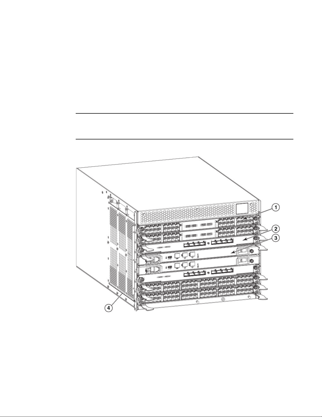
FIGURE 1 Port side of the Brocade DCX 8510-4 (sample configuration)
1. Port blade (FC16-32)
2. Core switch blade (CR16-4)
3. Control processor blade (CP8)
4. Exhaust vent
Brocade DCX 8510-4 Backbone Hardware Reference Manual 15
53-1002177-07
Page 16
Nonport side of the Brocade DCX 8510-4
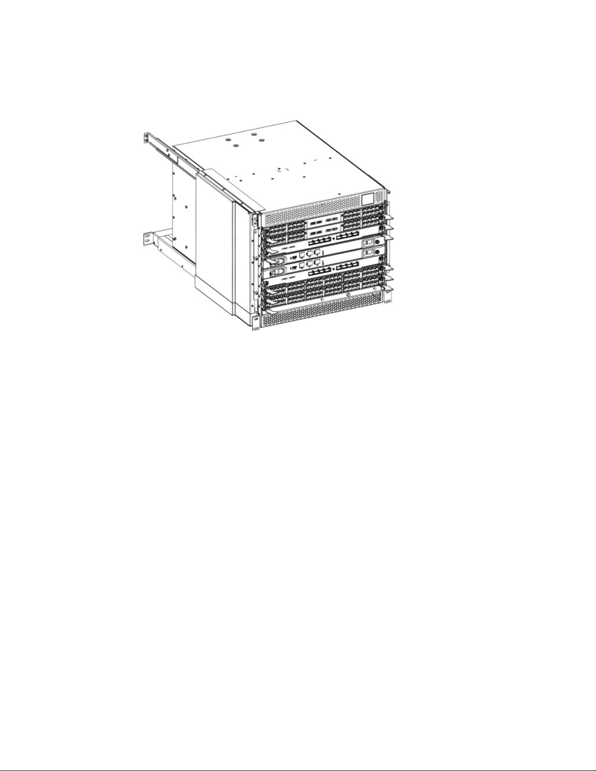
FIGURE 2 Port side of the Brocade DCX 8510-4 with the Port Side Exhaust Kit installed (sample
configuration)
Nonport side of the Brocade DCX 8510-4
The following figure shows a sample configuration of the nonport side view of the Brocade DCX
8510-4.
16 Brocade DCX 8510-4 Backbone Hardware Reference Manual
53-1002177-07
Page 17
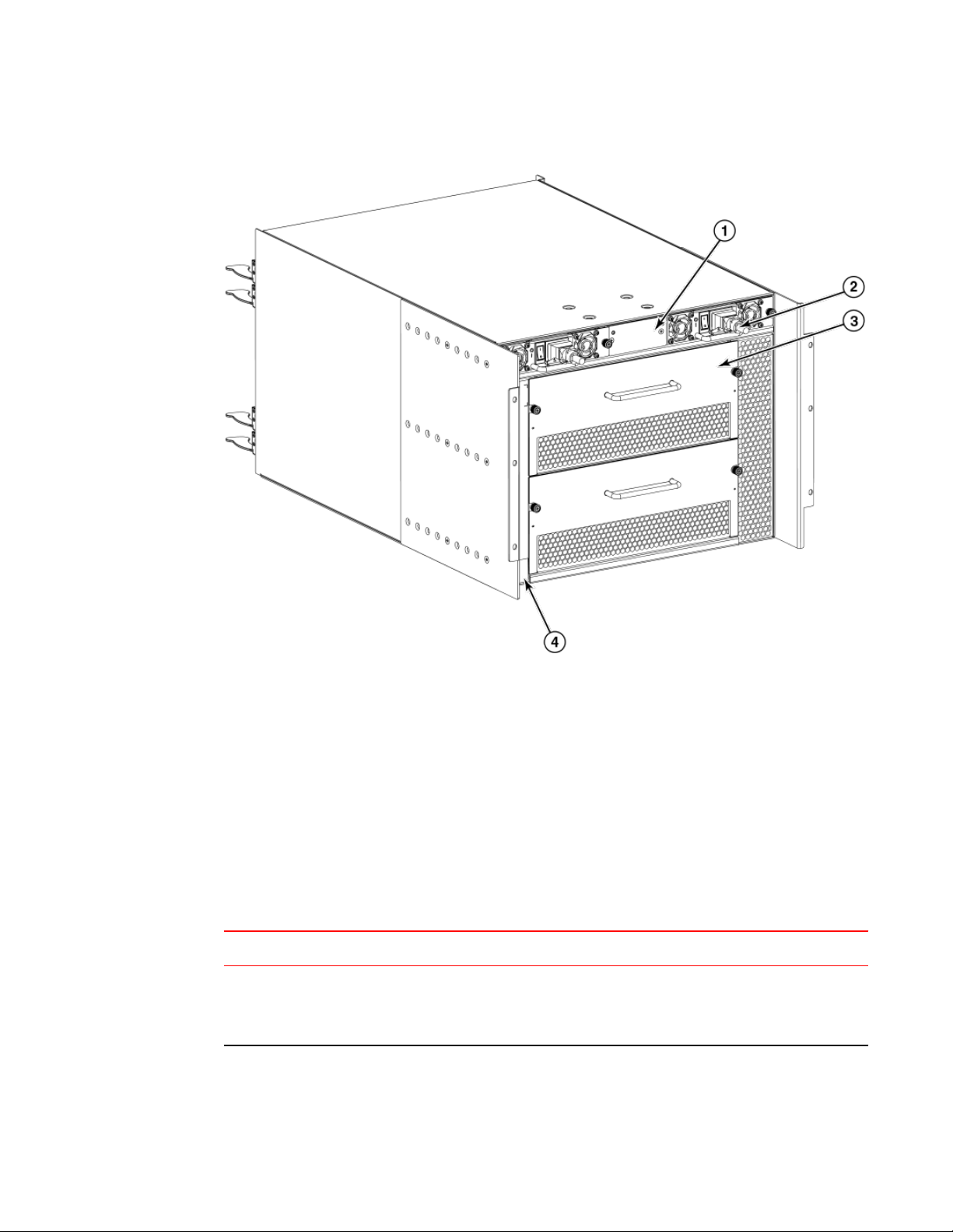
FIGURE 3 Nonport side of the Brocade DCX 8510-4 (sample configuration)
Brocade DCX 8510-4 blades
1. WWN card bezel (logo plate)
2. Power supply
3. Blower assembly
4. Label with serial number and WWN
Brocade DCX 8510-4 blades
The following table summarizes the port, application, control processor, and core switch blades that are
available for the Brocade DCX 8510-4.
Blades available for the Brocade DCX 8510-4TABLE 1
Description Name Function
Brocade DCX 8510-4
control processor
blade
CP8 The CP8 blade contains the control plane for the chassis. There are two CP8
blades for redundancy. This control processor blade is compatible with the
Brocade DCX 8510-8, Brocade DCX 8510-4, Brocade DCX, and Brocade
DCX-4S.
Brocade DCX 8510-4 Backbone Hardware Reference Manual 17
53-1002177-07
Page 18

Brocade DCX 8510-4 Overview
Description Name Function
Blades available for the Brocade DCX 8510-4 (Continued)TABLE 1
Brocade DCX 8510-4
core switch blade
32-port 8-Gbps port
blade
48-port 8-Gbps port
blade
64-port 8-Gbps port
blade
32-port 16-Gbps port
blade
48-port 16-Gbps port
blade
CR16-4 The CR16-4 blade contains the ASICs for switching between port blades. Every
port blade connects to each core switch blade. There can be up to 192 16 Gbps
(256 8 Gbps) total ports for port blades. Each core switch blade connects to 128
backplane ports. Core switch blades have additional front port connectivity to
connect multiple chassis and backplane connections for the storage server
blade. This core switch blade is compatible only with the Brocade DCX 8510-4.
FC8-32E A 32-port Brocade port blade supporting 2, 4, and 8 Gbps Fibre Channel port
speeds. This port blade is compatible with the Brocade DCX 8510-8 and
Brocade DCX 8510-4. This blade requires Fabric OS v7.0.1 or later to run in this
chassis.
FC8-48E A 48-port Brocade port blade supporting 2, 4, and 8 Gbps Fibre Channel port
speeds. This port blade is compatible with the Brocade DCX 8510-8 and
Brocade DCX 8510-4. This blade requires Fabric OS v7.0.1 or later to run in this
chassis.
FC8-64 A 64-port Brocade port blade supporting 2, 4, and 8 Gbps port speeds with
mSFPs. This port blade is compatible with the Brocade DCX 8510-8, Brocade
DCX 8510-4, Brocade DCX, and Brocade DCX-4S.
FC16-32 A 32-port Brocade port blade supporting 2, 4, 8, 10, and 16 Gbps Fibre Channel
port speeds. The blade also supports port-based in-flight encryption/decryption
and compression/decompression. This port blade is compatible with the Brocade
DCX 8510-8 and Brocade DCX 8510-4 and requires Fabric OS v7.0.0 or later to
run in this chassis.
FC16-48 A 48-port Brocade port blade supporting 2, 4, 8, 10, and 16 Gbps Fibre Channel
port speeds. The blade also supports port-based in-flight encryption/decryption
and compression/decompression. This port blade is compatible with the Brocade
DCX 8510-8 and Brocade DCX 8510-4 and requires Fabric OS v7.0.0 or later to
run in this chassis.
64-port 16-Gbps port
blade
Storage encryption
blade
FCIP extension blade FX8-24 The FX8-24 blade enables FCIP functionality over existing IP infrastructure. It
18 Brocade DCX 8510-4 Backbone Hardware Reference Manual
FC16-64 A 64-port Brocade port blade supporting 4, 8, and 16 Gbps Fibre Channel port
speeds. The blade also supports port-based in-flight encryption/decryption and
compression/decompression. This port blade is compatible with the Brocade
DCX 8510-8 and Brocade DCX 8510-4 and requires Fabric OS v7.3.0 or later to
run in this chassis.
FS8-18 The FS8-18 blade enables data cryptographic (encryption/decryption) and data-
compression capabilities for data-at-rest. It has 16 Fibre Channel optical SFP
ports. This application blade is compatible with the Brocade DCX 8510-8,
Brocade DCX 8510-4, Brocade DCX, and Brocade DCX-4S and requires Fabric
OS v7.0.0 or later to run in the Brocade DCX 8510-4 and DCX 8510-8 chassis.
has 12 FC ports, 10 1-GbE ports, and two 10-GbE ports available. This
application blade is compatible with the Brocade DCX 8510-8, Brocade DCX
8510-4, Brocade DCX, and Brocade DCX-4S and requires Fabric OS v7.0.0 or
later to run in the Brocade DCX 8510-4 and DCX 8510-8 chassis.
53-1002177-07
Page 19

High availability
The following features contribute to the Brocade DCX 8510-4 high availability design:
• Redundant, hot-swappable FRUs, including blades, power supplies, blowers, and WWN cards
• Enhanced data integrity on all data paths
• Fabric Shortest Path First (FSPF) rerouting around failed links
• Integration with Simple Network Management Protocol (SNMP) managers
• Automatic control processor failover
• Nondisruptive "hot" software code loads and activation
• Easy configuration, save, and restore
The high availability software architecture of the Brocade DCX 8510-4 provides a common framework
for all applications that reside on the system, allowing global and local states to be maintained through
any component failure. High availability elements consist of the High Availability Manager, the
heartbeat, the fault/health framework, the replicated database, initialization, and software upgrade.
The High Availability Manager controls access to the standby control processor, facilitates software
upgrades, prevents extraneous CP failover activity, closes and flushes streams, provides flow control
and message buffering, and supports a centralized active and standby state.
High availability
Reliability
Serviceability
The Brocade DCX 8510-4 uses the following error detection and correction mechanisms to ensure
reliability of data:
• Error Detection and Correction over main control processor memory.
• Error Detection and Correction mechanism, which checks for encoder errors and fault isolation
(EDFI), such as cyclic redundancy checking (CRC), parity checking, checksum, and illegal address
checking.
• Power-on self-test (POST).
• Dual control processors that enable hot, nondisruptive fast firmware upgrades.
• One serial port and two Ethernet ports (on each control processor) for management and for service.
Offline control processor diagnostics and remote diagnostics simplify troubleshooting. The standby
control processor monitors diagnostics to ensure the system is operational should a failover be
necessary.
• Bus monitoring and control of blades and other field-replaceable units (FRUs).
The Brocade DCX 8510-4 provides the following features to enhance and ensure serviceability:
• Modular design with hot-swappable components.
• Flash memory that stores two firmware images per control processor.
• USB port on control processor blades for most tasks that formerly required an FTP/SCP server,
including software and firmware upgrades.
• Nonvolatile random-access memory (NVRAM), containing the OEM serial number, Brocade serial
number, revision information, and part number information.
• Background health-check daemon.
Brocade DCX 8510-4 Backbone Hardware Reference Manual 19
53-1002177-07
Page 20

Software features
• Memory scrubber, self test, and bus ping to determine if a bus is not functioning.
• RASlog messages.
• SMI-S compliant.
• Hardware and software watchdog timers.
• Status LEDs.
• Predictive diagnostics analysis through Fabric Watch.
• SNMP (including version 3) integration with higher-layer managers.
Software features
The Fabric OS allows any Fibre Channel-compliant device to attach to the switches as long as it
conforms to the device login, name service, and related Fibre Channel standards. Each operating
environment requires that a Fibre Channel host bus adapter (HBA) be available with a standardscompliant driver for correct interface to the fabric.
Fabric OS consists of a set of embedded applications running on top of an embedded Linux operating
system kernel. Some of these applications include:
• Name server
• Alias server
• Zone server
• Simple Network Management Protocol (SNMP) agent
• SMI-S-compliant API
• Syslog auditing
• Reliable Commit Service (RCS)
• NTP
• Tasks to manage address assignment, routing, link initialization, fabric initialization, link shutdown,
Brocade DCX 8510-4 shutdown, and the user interface
Security
The following list highlights some of the key security features available for the Brocade DCX 8510-4
and for other Brocade enterprise-class products running Fabric OS 7.0.1 or later. For details, contact
your Brocade DCX 8510-4 supplier and refer to the Brocade White Paper, "The Growing Need for
Security in Storage Area Networks."
• DH-CHAP
• SSHv2 (using AES, 3DES, RSA)
• HTTPS (using AES)
• SNMPv3
• FC-SP
• Secure RPC
• Secure file copy (SCP)
• Telnet disable
• Telnet timeout
• IP filters (block listeners)
• Secure passwords (centralized control through RADIUS/CHAP)
• Multiple user accounts (MUAs) (Up to 255)
• Role-based access controls (RBACs)
20 Brocade DCX 8510-4 Backbone Hardware Reference Manual
53-1002177-07
Page 21

Network manageability
• Administrative domains/Virtual fabrics
• Boot PROM password reset
• Password hardening policies
• Up front login in Web Tools
• Login banner
• Monitoring of attempted security breaches (through audit logging)
• Monitoring of attempted security breaches (through Fabric Watch Security Class)
• Fibre Channel security policies: DCC and SCC
• Trusted Switch (FCS) for central security management
• Management access controls (SNMPv3, Telnet, FTP, serial port, front panel)
• Hardware-enforced zoning by WWN, domain/port ID, or both
• Default zoning
• RSCN suppression and aggregation
• Configurable RSCN suppression by port
• NTPv3 (to synchronize timestamps)
• Event auditing
• Change tracking
• Firmware change alerts in Fabric Manager
• Persistent port disable
• Persistent domain ID
• E_Port disable
Network manageability
The Brocade DCX 8510-4 has a single domain and is managed as a single element with Brocade
Network Advisor. The Brocade DCX 8510-4 responds to its own IP address and appears as a separate
entity to the Telnet protocol and SNMP.
All management interfaces, such as Telnet, Web Tools, standards-compliant SMI-S, and Management
Server, support a "port N within blade M" naming scheme.
The Brocade DCX 8510-4 supports SNMPv1 and SNMPv3. When SNMP devices send SNMP
messages to a management console running SAN management software, the information is stored in a
management information base (MIB). Fabric OS v7.0.0 and later supports the latest Fibre Alliance Fibre
Channel Management (FCMGMT) and Storage Management Initiative (SMI) MIBs, which allow
common information necessary for management software to provide information to a SAN
administrator. Refer to the Fabric OS MIB Reference for additional MIB information.
Brocade DCX 8510-4 Backbone Hardware Reference Manual 21
53-1002177-07
Page 22

Network manageability
22 Brocade DCX 8510-4 Backbone Hardware Reference Manual
53-1002177-07
Page 23

Installation of the Brocade DCX 8510-4
● Time and items required................................................................................................. 23
● Preparing for the Brocade DCX 8510-4 installation........................................................ 24
● Unpacking and installing the Brocade DCX 8510-4........................................................ 25
● Items included with the Brocade DCX 8510-4................................................................ 26
● Providing power to the Brocade DCX 8510-4 Backbone................................................ 27
● Port numbering................................................................................................................27
● Chassis slots................................................................................................................... 29
● Cable management.........................................................................................................29
Time and items required
You can set up and install the Brocade DCX 8510-4 in the following ways:
• As a standalone unit on a flat surface.
• In a 19-in. Electronic Industries Association (EIA) cabinet, using a Brocade DCX 8510-4, DCX-4S
Rack Mount Kit (either a 27-31 in. or 18-24 in. kit depending on rack used).
• In a chassis with the Port Side Exhaust Kit (provided) in an approved rack.
• In a mid-mount telecommunications (Telco) rack, using the Mid-Mount Rack Kit available from your
Brocade DCX 8510-4 supplier.
This chapter describes how to set up the Brocade DCX 8510-4 as a standalone unit. For rack-mount
installation instructions, refer to the appropriate manual as described in the following table.
The following table describes the main installation and setup tasks, the estimated time required for
each, and the items required to complete the task based on a fully populated Brocade DCX 8510-4 (256
Fibre Channel ports using the FC16-64 port blades). Configurations with fewer ports require less time.
These time estimates assume a prepared installation site and appropriate power and network
connectivity.
Installation tasks, time, and items required TABLE 2
Installation task Time estimate Items required
Site preparation and unpacking
Brocade DCX 8510-4
Installing rack mount kit or Port
Side Exhaust Kit
Mounting and securing Brocade
DCX 8510-4 in rack
Brocade DCX 8510-4 Backbone Hardware Reference Manual 23
53-1002177-07
30 minutes 1/2-in. socket wrench (to remove pallet bolts).
Pallet jack.
Hydraulic lift or assisted lift, able to raise to a minimum of
140 cm (55 in.), with a minimum capacity of 113 kg (250 lb).
The Brocade DCX 8510-4 weighs 68 kg (150 lb) with four
FC16-48 port blades installed (192 ports).
30 minutes Refer to the one or more of the following if you are mounting
30 minutes
the Brocade DCX 8510-4 in a rack: Brocade Port Side
Exhaust Kit Installation Procedure, Mid-Mount Rack Kit
(Backbone) Installation Procedure, or 27-31 Inch Rail Rack
Mount (Backbone) Kit Installation Procedure.
Page 24

Preparing for the Brocade DCX 8510-4 installation
Installation tasks, time, and items required (Continued)TABLE 2
Installation task Time estimate Items required
Installing power cables and
powering on the Brocade DCX
8510-4
Establishing serial connection,
logging in to Brocade DCX
8510-4, and configuring IP
addresses
Installing an Ethernet cable,
opening a Telnet session, and
configuring the Brocade DCX
8510-4 domain ID, date and
time, and additional system
parameters. Verify and back up
configuration.
Installing transceivers as needed 20 minutes
Attaching fiber-optic cables,
cable ties, and cable guides
20 minutes Power cables (provided in the Brocade DCX 8510-4
20 minutes Serial cable (provided in the accessory kit).
20 minutes Ethernet cabling (optional) for Telnet access.
(longer if using
high-density port
blades)
2-3 hours Fiber-optic cables and cable ties.
accessory kit).
Workstation computer with a serial port or terminal server
port and a terminal emulator application (such as
HyperTerminal).
Ethernet IP addresses for the Brocade DCX 8510-4 chassis
and for both control processor blades: total three addresses.
Refer to the Fabric OS Administrator's Guide.
SFP+, mSFP, and QSFP optical transceivers as needed.
Preparing for the Brocade DCX 8510-4 installation
NOTE
Read the Caution and Danger Notices on page 145 before installation. Read Power specifications on
page 117 to plan for meeting power supply standards before installing the chassis. Read Managing
cables on page 42 to plan for cable management.
The following steps are required to ensure correct installation and operation.
1. Provide a space that is 9 rack units (9U) high, 61.19 cm (24.09 in.) deep, and 43.74 cm (17.22 in.)
wide. 1U is equal to 4.45 cm (1.75 in.). If you do not use the provided Port Side Exhaust Kit, the
space needs to be only 8 rack units (8U) high.
Plan to install the Brocade DCX 8510-4 with the nonport side facing the air-intake aisle. The
Brocade DCX 8510-4 can be installed facing either direction, if serviceability and cooling
requirements are met.
2. Ensure that dedicated electrical branch circuits with the following characteristics are available:
NOTE
Refer to Power specifications on page 117 for specific requirements depending on your chassis
configuration.
24 Brocade DCX 8510-4 Backbone Hardware Reference Manual
53-1002177-07
Page 25
Unpacking and installing the Brocade DCX 8510-4
• 200 - 240 VAC, 50-60 Hz (two branch circuits) - recommended for high availability and maximum
blade usage
• Two cables for 200 - 240 VAC service
• Protected by a circuit breaker in accordance with local electrical codes
• Supply circuit, line fusing, and wire size adequate to the electrical rating on the chassis nameplate
• Location close to the chassis and easily accessible
• Grounded outlets installed by a licensed electrician and compatible with the power cords
CAUTION
Use a separate branch circuit for each power cord, which provides redundancy in case one of
the circuits fails.
3. Plan for cable management before installing the chassis.
Cables can be managed in a variety of ways, such as by routing cables below the chassis, to either
side of the chassis, through cable channels on the sides of the cabinet, or by using patch panels.
4. Ensure that the following is available for configuration of the Brocade DCX 8510-4:
• Workstation with an installed terminal emulator, such as HyperTerminal
• Serial cable (provided)
• Three Ethernet cables (including one spare)
• Access to an FTP server for backing up the switch configuration or collecting supportsave output
data (optional)
• A Brocade USB stick for collecting supportsave output data (optional)
• Transceivers (copper and optical) and compatible cables
5. Ensure that the air intake and exhaust vents have a minimum of 5.1 cm (2 in.) of airspace.
6. Ensure that the air temperature on the air intake side is less than 40°C (104°F) during operation.
Unpacking and installing the Brocade DCX 8510-4
Use the following procedure to unpack and install your Brocade DCX 8510-4.
DANGER
A fully populated Brocade DCX 8510-4 (four FC16-64 port cards, 256 ports) weighs
approximately 69 kg (152 lbs) and requires a hydraulic or assisted lift to install it.
1. Unpack the Brocade DCX 8510-4.
a) Cut the bands that encircle the packaging.
b) Remove the lid and the kits and foam from the top of the chassis.
c) Lift the cardboard box off the chassis and remove the plastic bag from around the
chassis.Save the packing materials for use when returning the old chassis.
d) Leave the chassis on top of the plastic shipping tray if the chassis must be transported to
the installation location.
NOTE
The Brocade DCX 8510-4 packaging does not incorporate a wood pallet and pallet
brackets. The chassis sits on top of a plastic shipping tray.
2. Use a pallet jack or other assisted lift to transport the new chassis to the installation area. Doorways
must be wider than 36 in. (91 cm) to accommodate the chassis.
Brocade DCX 8510-4 Backbone Hardware Reference Manual 25
53-1002177-07
Page 26

Items included with the Brocade DCX 8510-4
3. Remove the Brocade DCX 8510-4 Port Side Exhaust Kit (if ordered), accessory kit, packing foam,
and antistatic plastic from the chassis and set aside.
4. Remove the chassis door from the Brocade DCX 8510-4.
5. Remove the vertical cable management fingers.
6. Use a lift to raise the chassis to the correct level. If installing the chassis in a cabinet, follow the
instructions provided by the rack kit manufacturer.
7. If applicable, lock the wheels of the lift.
8. Gently slide the chassis onto the final installation surface, ensuring that it remains supported during
the transfer.
9. Ensure that the chassis is oriented so that the nonport side has access to intake air (cool).
10.Reinstall the vertical cable management fingers.
11.Reinstall the door. The door must be installed to meet EMI compliance.
Items included with the Brocade DCX 8510-4
The Brocade DCX 8510-4 ships with the following:
• Brocade DCX 8510-4 chassis, populated with:
‐ Control processor blades (CP8)
‐ Core switch blades (CR16-4)
‐ Port blades, application blades, and encryption blades (included based on customer
specification)
‐ Blade slot filler panels (for slots not filled by blades)
‐ Port Side Exhaust Kit (included based on customer specification)
‐ WWN cards
‐ WWN bezel (logo plate)
‐ Power supplies
‐ Power supply filler panel (included if there is only one power supply)
‐ Blower assemblies
‐ Cable management finger assemblies
‐ Chassis door
• Accessory kit containing the following items:
‐ Brocade DCX 8510-4 Backbone QuickStart Guide
‐ ESD grounding strap
‐ USB device
‐ RS-232 serial cable. The RS-232 cable has an adapter at one end that can be removed to
provide an RJ-45 style connector.
• Rack mount kit (as ordered) with instructions
Order the Brocade-branded optical transceivers (SFP+, mSFP, and QSFP). The Brocade DCX 8510-4
supports SWL, LWL, and ELWL transceivers. The mSFPs and QSFPs are SWL transceivers only.
NOTE
For information about the SFP+, mSFP, and QSFP transceivers that are qualified for the Brocade DCX
8510-4, refer to Transceiver removal and replacement on page 87.
26 Brocade DCX 8510-4 Backbone Hardware Reference Manual
53-1002177-07
Page 27

Providing power to the Brocade DCX 8510-4 Backbone
Providing power to the Brocade DCX 8510-4 Backbone
For this procedure, refer to Power specifications on page 117 for power supply requirements for your
chassis.
Complete the following steps to provide power to the chassis.
DANGER
Make sure that the power source circuits are properly grounded, then use the power cord
supplied with the device to connect it to the power source.
1. Connect the two AC power cords to the two power supplies.
2. Connect the power cords to a power source with voltage of 200 to 240 VAC, 47 to 63 Hz or optionally
to a power source with voltage of 110 to 120 VAC, 47 to 63 Hz. If using any application blades in the
chassis, the 200 to 240 VAC option is necessary to achieve power supply redundancy.
NOTE
Use of the high-voltage line (200 to 240 VAC) is highly recommended because of better powerconversion efficiency. For a fully-loaded DCX 8510-4, 200 to 240 VAC is required for high availability
(ability to hot swap a failed power supply without affecting system operation).
3. Switch the AC power switches on the power supplies to I. The AC power switches light green when
switched on and power is supplied.
The Brocade DCX 8510-4 performs a power-on self-test (POST) each time it is powered on. POST
takes approximately 10 minutes and is complete when the indicator light activity displays the
operational state. You can bypass POST by using the fastBoot command. You can also disable
POST for successive reboots on the Brocade DCX 8510-4 using the diagDisablePost command.
NOTE
Do not connect the switch to the network until the IP addresses are configured.
For information about LED patterns, refer to Monitoring System Components on page 45.
Port numbering
The Brocade DCX 8510-4 uses the following port numbering method (Port Numbering Template on
page 137):
Blade
FC8-32E port
blade
Port numbering Trunking port groups
• 0 through 15 from right to left on the lower set of
ports.
• 16 through 31 from right to left on the upper set of
ports.
• 0-7, 8-15, 16-23, and 24-31.
Brocade DCX 8510-4 Backbone Hardware Reference Manual 27
53-1002177-07
Page 28

Installation of the Brocade DCX 8510-4
Blade Port numbering Trunking port groups
FC8-48E port
blade
FC8-64 port
blade
FC16-32 port
blade
FC16-48 port
blade
FC16-64 port
blade
CR16-4 core
blade
• 0 through 23 from right to left on the lower set of
ports.
• 24 through 47 from right to left on the upper set of
ports.
• 0 through 31 from right to left on the lower set of
ports.
• 32 through 63 from right to left on the upper set of
ports.
• 0 through 15 from right to left on the lower set of
ports.
• 16 through 31 from right to left on the upper set of
ports.
• 0 through 23 from right to left on the lower set of
ports.
• 24 through 47 from right to left on the upper set of
ports.
• 0 through 63 from right to left.
These are QSFP ports 0-15. For supported QSFPs,
refer to Qualified transceivers for the FC16-64 port
blade and the core blades on page 40.
• ICL connectors are numbered from 0 through 7 from
right to left .
Each connector is a group of four 16-Gbps ports. For
supported QSFPs, refer to Qualified transceivers for
the FC16-64 port blade and the core blades on page
40
• 0-7, 8-15, 16-23, 24-31, 32-39,
40-47.
• 0-7, 8-15, 16-23, 24-31, 32-39,
40-47, 48-55, and 56-63.
• 0-7, 8-15, 16-23, and 24-31.
• 0-7, 8-15, 16-23, 24-31, 32-39,
40-47.
• 0-7, 8-15, 16-23, 24-31, 32-39,
40-47, 48-55, and 56-63.
• Trunk group 0: FC ports 0-3
• Trunk group 1: FC ports 4-7
NOTE
Individual FC ports within the same
QSFP port cannot form a trunk. A
trunk has to comprise of individual
FC ports from different consecutive
QSFP ports. Only four FC ports from
consecutive QSFP ports can form a
trunk in Brocade DCX 8510-4
FS8-18 blade • The 16 physical Fibre Channel ports on this blade
are numbered 0 through 15 from right to left.
• The two 10/100/1000 BaseT ports are numbered
from the bottom as GE0 and GE1.
FX8-24 blade Ports are numbered in groups.
• The FC ports are numbered from 0 through 11 in two
horizontal rows of six ports starting from the lower
right and upper right in the right group of 12 ports.
They are labeled FC on the front panel diagram.
• The two 10-GbE ports are 0 and 1 and are in the
lower row to the left of the FC ports. They are labeled
10GE on the front panel diagram.
• The GbE ports are numbered 0 through 9 and are in
both rows to the left of the FC and 10GE ports. They
are labeled GE on the front panel diagram.
28 Brocade DCX 8510-4 Backbone Hardware Reference Manual
• 0-7 and 8-15.
Up to three FC trunking groups are
permitted. The three groups are
defined as follows:
• Trunk group 0: FC ports 0, 1
• Trunk group 1: FC ports 6, 7
• Trunk group 2: FC ports 2, 3, 4, 5,
8, 9, 10, 11
53-1002177-07
Page 29

Chassis slots
Chassis slots are numbered 1 through 8, from bottom to top when facing the port side of the Brocade
DCX 8510-4. Control processor blades (CP8) can be installed only in slots 4 and 5. Core switch blades
(CR16-4) can be installed only in slots 3 and 6. The rest of the slots, 1, 2, 7, and 8, can be filled with
port, application, or encryption blades. Unused slots must be filled with blade filler panels to maintain
adequate cooling.
Cable management
The cable management finger assemblies are attached to the chassis on either side of the port side of
the chassis and allow for simple cable management. The cable management finger assemblies can be
installed without service disruption.
Route the cables across in front of the blades to keep LEDs visible. Leave at least one meter of slack
for each fiber-optic cable to provide room to remove and replace blades.
Chassis slots
NOTE
The minimum radius to which a 50 micron cable can be bent under full tensile load is 5.1 cm (2 in.). For
a cable under no tensile load, that minimum is 3.0 cm (1.2 in.).
CAUTION
Before plugging a cable into to any port, be sure to discharge the voltage stored on the cable by
touching the electrical contacts to ground surface.
Cables can be organized and managed in a variety of ways, for example, using cable channels on the
sides of the cabinet or patch panels to minimize cable management. Following is a list of
recommendations:
NOTE
You should not use tie wraps with optical cables because they are easily overtightened and can
damage the optic fibers.
• Plan for rack space required for cable management before installing the switch.
• Leave at least 1 m (3.28 ft) of slack for each port cable. This provides room to remove and replace
the switch, allows for inadvertent movement of the rack, and helps prevent the cables from being
bent to less than the minimum bend radius.
• If you are using Brocade ISL Trunking, consider grouping cables by trunking groups. The cables
used in trunking groups must meet specific requirements, as described in the Fabric OS
Administrator’s Guide .
• For easier maintenance, label the fiber-optic cables and record the devices to which they are
connected.
• Keep LEDs visible by routing port cables and other cables away from the LEDs.
• Use Velcro ® type straps to secure and organize fiber-optic cables.
Brocade DCX 8510-4 Backbone Hardware Reference Manual 29
53-1002177-07
Page 30
High-density cabling
NOTE
Do not route the cables in front of the air exhaust vent, which is located at the top of the port side of
the chassis. If you are using the Port Side Exhaust Kit with your Brocade DCX 8510-4, there is also an
exhaust vent at the bottom of the port side of the chassis. Use the cable management finger
assemblies to keep the cables away from this exhaust vent as well.
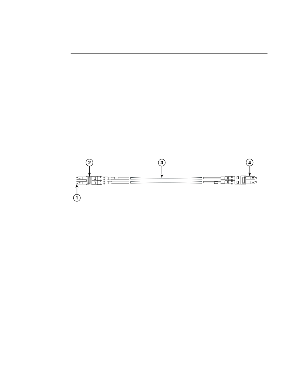
High-density cabling
The FC8-64 high density port blade cannot use the standard LC cables because the pitch between
optics in the new mini-SFP (mSFP) transceiver is smaller than in standard SFPs. Patch cables and
panels can be used to attach standard size cabling to the blade if necessary. The following figure
illustrates the mSFP to SFP patch cable. Refer to "Best Practices Guide: High Density Cable
Management Solutions" (available at http://www.brocade.com ) for cable management guidelines for
high-density port solutions, and cable and patch panel part numbers.
FIGURE 4 Cable design for the mSFP patch cables for the FC8-64 high density port blade
1. mSFP connector
2. Duplex clip (black)
3. 6 mm cable
4. SFP connector
Note that the duplex clip on the mSFP end of the cable is black for easier recognition. For a listing of
the qualified mSFP optical cables for the FC8-64 port blade, refer to Qualified cables for the FC8-64
port blade on page 124.
If ISL Trunking is in use, group the cables by trunking group. The ports are color-coded to indicate
which ports can be used in the same ISL Trunking group: eight ports marked with solid black ovals
alternate with eight ports marked with oval outlines.
Installing ICL cables
Refer to Inter-chassis link (ICL) cable removal and replacement on page 92 for the procedure to
install the ICL QSFP cables
30 Brocade DCX 8510-4 Backbone Hardware Reference Manual
53-1002177-07
Page 31

Logging In and Configuring the Brocade DCX 8510-4
● Configuring the Brocade DCX 8510-4.............................................................................31
● Establishing a serial connection to the Brocade DCX 8510-4.........................................32
● Logging in to the serial console port............................................................................... 33
● Configuring the IP addresses..........................................................................................34
● Logging off the serial console port and disconnecting the serial cable........................... 35
● Establishing an Ethernet connection to the Brocade DCX 8510-4..................................35
● Customizing a switch name............................................................................................ 36
● Customizing a chassis name.......................................................................................... 36
● Setting the domain ID......................................................................................................36
● Setting the date and time................................................................................................ 37
● Verifying the PID mode................................................................................................... 39
● Determining installed software licenses.......................................................................... 39
● Installing transceivers and attaching cables....................................................................39
● Managing cables............................................................................................................. 42
● Verifying correct operation and backing up the configuration......................................... 43
● Powering off the Brocade DCX 8510-4........................................................................... 44
Configuring the Brocade DCX 8510-4
The Brocade DCX 8510-4 must be configured before it is connected to the fabric, and all of the
configuration commands must be entered through the active CP blade. The Brocade DCX 8510-4
configuration includes the following parameters:
• IP address and subnet mask for the chassis
• IP addresses, host names, subnet masks, and gateway addresses for both CP blades
• Switch name
• Domain ID for the Brocade DCX 8510-4 (optional)
• WWN for the Brocade DCX 8510-4
The Brocade DCX 8510-4 WWN is initially set by the factory to match the license ID (which is based on
the chassis serial number). The WWN can be changed but the license ID cannot be modified.
The configuration information is mirrored to the standby CP blade, which allows the current
configuration to remain available even if the active CP blade fails. The configuration information for the
Brocade DCX 8510-4 is stored in the WWN cards and the flash memory of the CP blades. The
configuration can be backed up to a workstation (uploaded) and then downloaded to the active CP
blade if necessary.
NOTE
If the Brocade FS8-18 encryption blade is installed, refer to the Fabric OS Encryption Administrator’s
Guide for the procedures to configure the encryption functions.
The following figure illustrates the flow of the basic configuration tasks.
Brocade DCX 8510-4 Backbone Hardware Reference Manual
53-1002177-07
31
Page 32

Establishing a serial connection to the Brocade DCX 8510-4
FIGURE 5 Configuration tasks
Establishing a serial connection to the Brocade DCX 8510-4
To establish a serial connection to the console port on the Brocade DCX 8510-4, complete the
following steps.
1. Verify that the Brocade DCX 8510-4 is powered on and that POST is complete by verifying that all
power LED indicators on the port, control processor, and core switch blades display a steady green
light.
2. Remove the shipping cap from the CONSOLE port on the active CP. Use the serial cable provided
with the Brocade DCX 8510-4 to connect the CONSOLE port on the active CP to a computer
workstation. The active CP blade is indicated by an illuminated (blue) LED.
32 Brocade DCX 8510-4 Backbone Hardware Reference Manual
53-1002177-07
Page 33

Logging in to the serial console port
NOTE
The CONSOLE port is intended primarily for the initial setting of the IP address and for service
purposes.
3. Access the Brocade DCX 8510-4 using a terminal emulator application (such as HyperTerminal in a
Windows environment or tip in a UNIX environment).
4. Disable any serial communication programs running on the workstation (such as synchronization
programs).
5. Open a terminal emulator application (such as HyperTerminal on a PC, or term, tip, or kermit in a
UNIX environment), and configure the application as follows:
• In a Windows environment:
Parameter Value
Bits per second 9600
Data bits 8
Parity None
Stop bits 1
Flow control None
• In a UNIX environment, enter the following string at the prompt:
tip /dev/ttyb -9600
If ttyb is already in use, use ttya instead and enter the following string at the prompt:
tip /dev/ttya -9600
When the terminal emulator application stops reporting information, press Enter. You receive the
following login prompt:
CP0 Console Login:
6. Proceed to the next task.
Logging in to the serial console port
To log in to the Brocade DCX 8510-4 through the serial connection, follow these steps.
1. Log in to the Brocade DCX 8510-4 as admin. The default password is password. At the initial login,
you are prompted to enter new admin and user passwords. Make sure to write down the new
passwords and keep this information in a secure location.
Fabric OS (swDir)
swDir login: admin
Password:
Please change your passwords now.
Use Control-C to exit or press 'Enter' key to proceed.
Brocade DCX 8510-4 Backbone Hardware Reference Manual 33
53-1002177-07
Page 34

Configuring the IP addresses
swDir:admin>
2. (Optional) Modify passwords. To skip modifying the password, press Ctrl+C. For more information
on passwords, refer to the Fabric OS Administrator's Guide.
NOTE
Passwords can be 8 to 40 characters long. They must begin with an alphabetic character. They can
include numeric characters, the period (.), and the underscore (_) only. Passwords are casesensitive, and they are not displayed when you enter them on the command line. For more
information on passwords, refer to the Fabric OS Administrator's Guide.
Configuring the IP addresses
The Brocade DCX 8510-4 requires three IP addresses, which are configured using the ipAddrSet
command. IP addresses are required for both CP blades (CP0 and CP1) and for the chassis
management IP (shown as SWITCH under the ipAddrShow command) in the Brocade DCX 8510-4.
NOTE
The default IP addresses and host names for the Brocade DCX 8510-4 are:
• 10.77.77.75 / CP0 (the CP blade in slot at the time of configuration)
• 10.77.77.74 / CP1 (the CP blade in slot at the time of configuration)
NOTE
Resetting an IP address while the Brocade DCX 8510-4 has active IP traffic or has management and
monitoring tools running, such as DCFM, Fabric Watch, and SNMP, can cause traffic to be interrupted
or stopped.
Complete the following steps to set the IP addresses for the Brocade DCX 8510-4.
1. Log in to the active CP as admin using the serial cable connection.
2. Set up the Brocade DCX 8510-4 IP address by entering the ipaddrset -chassis command:
swDir:admin> ipAddrSet -chassis
Enter the information at the prompts. Specify the -chassis IP address. The -sw 0 IP address is not
valid on this chassis.
NOTE
The addresses 10.0.0.0 through 10.0.0.255 are reserved and used internally by the Brocade DCX
8510-4. External IPs must not use these addresses.
3. Set up the CP0 IP address by entering the ipaddrset -cp 0 command:
swDir:admin> ipAddrSet -cp 0
Enter the information at the prompts.
4. Set up the CP1 IP address by entering the ipaddrset -cp 1 command:
swDir:admin> ipAddrSet -cp 1
34 Brocade DCX 8510-4 Backbone Hardware Reference Manual
53-1002177-07
Page 35

Logging off the serial console port and disconnecting the serial cable
Enter the information at the prompts.
This is a sample IP configuration:
swDir:admin> ipaddrset -chassis
Ethernet IP Address [0.0.0.0]: 192.168.1.1
Ethernet Subnetmask [0.0.0.0]: 255.255.255.0
Fibre Channel IP Address [0.0.0.0]:
Fibre Channel Subnetmask [0.0.0.0]:
Issuing gratuitous ARP...Done.
Committing configuration...Done.
swDir:admin>
ipaddrset -cp 0
Host Name [cp0]:
Ethernet IP Address [10.77.77.75]: 192.168.1.2
Ethernet Subnetmask [0.0.0.0
]: 255.255.255.0
Gateway IP Address [0.0.0.0
]: 192.168.1.254
IP address is being changed...Done.
Committing configuration...Done.
swDir:admin> ipaddrset -cp 1
Host Name [cp1]:
Ethernet IP Address [10.77.77.74]: 192.168.1.3
Ethernet Subnetmask [0.0.0.0]: 255.255.255.0
Gateway IP Address [0.0.0.0]: 192.168.1.254
IP address of remote CP is being changed...Done.
Committing configuration...Done.
Logging off the serial console port and disconnecting the serial cable
You can use the serial port to monitor error messages through the serial connection. If the serial port is
no longer required, use the logout command to log out of the serial console, remove the serial cable,
and replace the plug in the serial port.
Establishing an Ethernet connection to the Brocade DCX 8510-4
After using a serial connection to configure the IP addresses for the Brocade DCX 8510-4, you can
connect the active CP blade to the local area network (LAN).
NOTE
Connecting the CP blades to a private network or VLAN is recommended.
By establishing an Ethernet connection, you can complete the Brocade DCX 8510-4 configuration using
a serial session, Telnet, or management applications, such as Web Tools or Brocade Network Advisor.
Perform the following steps to establish an Ethernet connection to the Brocade DCX 8510-4.
1. Remove the shipping plug from the Ethernet port on the active CP blade.
2. Insert one end of an Ethernet cable into the Ethernet port.
3. Connect the other end to an Ethernet 10/100/1000 BaseT LAN.
Brocade DCX 8510-4 Backbone Hardware Reference Manual 35
53-1002177-07
Page 36

Customizing a switch name
The Brocade DCX 8510-4 can be accessed through a remote connection using the command line
via Telnet or any of the management tools, such as Web Tools or Brocade Network Advisor.
4. To complete any additional Brocade DCX 8510-4 configuration procedures through a Telnet
session, log in to the Brocade DCX 8510-4 by Telnet, using the admin login. The default password
is password.
Customizing a switch name
The switch name of the Brocade DCX 8510-4 can be up to 30 characters long using Fabric OS
release 7.0.0 or later; can include letters, numbers, hyphens, and underscore characters; and must
begin with a letter.
NOTE
Changing the name causes a domain address format RSCN to be issued.
1. Enter switchName followed by the new name in double quotes.
swDir:admin> switchName "swModularSwitch5"
Committing configuration...
Done.
swModularSwitch5:admin>
2. Record the new name for reference.
Customizing a chassis name
The chassis name of the Brocade DCX 8510-4 can be up to 15 characters long; can include letters,
numbers, hyphens, and underscore characters; and must begin with a letter.
1. Enter chassisName followed by the new name in double quotes.
switch:admin> chassisname
"DCX8510_chassis"
Committing configuration...
Done.
2. Enter chassisName by itself to show the name.
switch:admin> chassisname
DCX8510_chassis
3. Record the new name for reference.
Setting the domain ID
Each switch in the fabric must have a unique domain ID. The domain ID can be manually set through
the configure command or can be automatically set. The default domain ID for the Brocade DCX
8510-4 is 1. Use the fabricShow command to view the already assigned domain IDs.
1. Enter switchDisable to disable the Brocade DCX 8510-4.
2. Enter configure.
36 Brocade DCX 8510-4 Backbone Hardware Reference Manual
53-1002177-07
Page 37

3. Enter y at the Fabric parameters prompt:
Fabric parameters (yes, y, no, n): [no] y
4. Enter a unique domain ID:
Domain: (1.239) [1] 3
5. Complete the remaining prompts or press Ctrl+D to accept the settings and exit.
6. Enter switchEnable to re-enable the Brocade DCX 8510-4.
Setting the date and time
The date and time settings are used for logging events. Switch operation does not depend on the date
and time; a switch with an incorrect date and time value still functions properly. However, because the
date and time are used for logging, error detection, and troubleshooting, they should be set correctly.
Setting the date
Setting the date and time
To set the date, follow these steps.
1. If necessary, log on to the Brocade DCX 8510-4 by Telnet, using the admin account.
The default password is password.
2. Enter the date command, using the following syntax:
date "mmddHHMMyy"
The values are:
• mm is the month; valid values are 01 through 12.
• dd is the date; valid values are 01 through 31.
• HH is the hour; valid values are 00 through 23.
• MM is minutes; valid values are 00 through 59.
• yy is the year; valid values are 00 through 99 (values greater than 69 are interpreted as 1970
through 1999, and values less than 70 are interpreted as 2000 through 2069).
switch:admin> date
Fri Sep 28 17:01:48 UTC 2010
switch:admin> date "0927123010"
Thu Sep 27 12:30:00 UTC 2010
switch:admin>
Setting the time zone
You must perform the procedure on all chassis for which the time zone must be set. However, you only
need to set the time zone once on each switch, because the value is written to nonvolatile memory.
Use one of the two following procedures to set the time zone.
The following procedure describes how to set the current time zone using timezone_fmt mode to
Central Standard time.
1. Log in to the switch using the default password, which is password.
2. Enter the tsTimeZone command as follows:
switch:admin> tstimezone [--interactive]/ [, timezone_fmt]
Use timezone_fmt to set the time zone by Country/City or by time zone ID, such as PST.
Brocade DCX 8510-4 Backbone Hardware Reference Manual 37
53-1002177-07
Page 38

Synchronizing local time
The following procedure describes how to set the current time zone using
interactive mode to Pacific Standard Time.
1. Enter the tsTimeZone command as follows:
2. Enter the appropriate number or Ctrl+D to quit.
3. At the prompt, select a country location.
4. At the prompt, enter the appropriate number to specify the time zone region
The following example shows how to change the time zone to US/Central.
switch:admin> tstimezone
Time Zone : US/Pacific
switch:admin> tstimezone US/Central
switch:admin> tstimezone
Time Zone : US/Central
switch:admin> tstimezone --interactive
You are prompted to select a general location.
Please identify a location so that time zone rules can be set correctly.
or Ctrl+D to quit.
Synchronizing local time
To synchronize the local time of the principal or primary switch with that of an external NTP server,
follow these steps.
1. If necessary, log on to the switch by Telnet, using the admin account.
2. Enter the tsClockServer command:
switch:admin> tsclockserver
"<ntp1;ntp2>"
In this syntax, ntp1 is the IP address or DNS name of the first NTP server, which the switch must be
able to access. The variable ntp2 is the second NTP server and is optional. The operand
"<ntp1;ntp2>" is optional; by default, this value is LOCL, which uses the local clock of the principal
or primary switch as the clock server.
The tsClockServer command accepts multiple server addresses in IPv4, IPv6, or DNS name
formats. When multiple NTP server addresses are passed, tsClockServer sets the first obtainable
address as the active NTP server. The rest will be stored as backup servers that can take over if the
active NTP server fails. The principal or primary FCS switch synchronizes its time with the NTP
server every 64 seconds.
switch:admin> tsclockserver
LOCL
switch:admin> tsclockserver "132.163.135.131"
switch:admin> tsclockserver
132.163.135.131
switch:admin>
The following example shows how to set up more than one NTP server using a DNS name:
switch:admin> tsclockserver "10.32.170.1;10.32.170.2;ntp.localdomain.net"
Updating Clock Server configuration...done.
Updated with the NTP servers
Changes to the clock server value on the principal or primary FCS switch are
propagated to all switches in the fabric
38 Brocade DCX 8510-4 Backbone Hardware Reference Manual
53-1002177-07
Page 39

Verifying the PID mode
Before connecting the Brocade DCX 8510-4 to the fabric, verify that the WWN-based persistent port
identifier (PID) feature on the Brocade DCX 8510-4 matches the other switches in the fabric. This
parameter must be identical for all switches in the fabric and is set using the configure command as
shown in the following example:
switch:admin>configure
Configure...
Fabric parameters (yes, y, no, n): [no] y
Domain: (1..239) [1]
Enable a 256 Area Limit
(0 = No,
1 = Zero Based Area Assignment,
2 = Port Based Area Assignment): (0..2) [0] 1
WWN Based persistent PID (yes, y, no, n): [no] yes
<command output truncated>
You can check the PID setting using the configshow command as in the following example. You can
use the | grep -i pid qualifier to pinpoint the PID information.
switch:admin> configshow | grep -i pid
fabric.ops.mode.pidFormat:1
fabric.wwnPidMode:1
The 1 indicates that the WWN-based persistent PID feature is enabled. The default value is 0 for
disabled.
Verifying the PID mode
Determining installed software licenses
Depending on the vendor agreement, certain licenses are factory installed on the Brocade DCX 8510-4.
To determine which licenses are enabled, use the licenseShow command.
swDir:admin> licenseshow
AAbbccDDeeFFeeGG:
Web license
Zoning license
Extended Fabric license
Fabric Watch license
Performance Monitor license
Trunking license
Security license
In this example, the license key is AAbbccDDeeFFeeGG. Keep a copy of the license key for reference.
The 64-bit chassis ID is required to obtain and activate licenses for the Brocade DCX 8510-4. The
chassis ID is available through the licenseIdShow command. The licenseShow and licenseIdShow
commands must be entered on the active CP blade. Refer to the Fabric OS Administrator's Guide for
more information.
Installing transceivers and attaching cables
The following two sets of steps cover the installation of transceivers and cables for most SFPs and for
QSFPs.
Brocade DCX 8510-4 Backbone Hardware Reference Manual 39
53-1002177-07
Page 40

Installing SFP+ and mSFP transceivers and cables
Installing SFP+ and mSFP transceivers and cables
Complete the following steps to install SFP-type optical transceivers.
NOTE
mSFP transceivers are compatible only with the FC8-64 port blade. While they will fit in other blades,
this configuration is unsupported and will generate an error.
1. Add the optical transceivers and cables to the Fibre Channel ports.
The ports are color-coded to indicate which can be used in the same port group for trunking
(trunking port groups can be up to 8 ports). The ports and cables used in trunking groups must meet
specific requirements. Refer to the Fabric OS Administrator's Guide.
2. Position one of the optical transceivers so that the key is oriented correctly to the port. Insert the
transceiver into the port until it is firmly seated and the latching mechanism clicks.
Transceivers are keyed so that they can only be inserted with the correct orientation. If a transceiver
does not slide in easily, ensure that it is correctly oriented.
3. Position a cable so that the key (the ridge on one side of the cable connector) is aligned with the
slot in the transceiver. Insert the cable into the transceiver until the latching mechanism clicks.
Cables are keyed so that they can be inserted in only one way. If a cable does not slide in easily,
ensure that it is correctly oriented.
4. Repeat steps 1 through 3 for the remaining ports.
5. Organize the cables. Refer to Managing cables on page 42.
6. Verify the Brocade DCX 8510-4 and port status using the switchShow command.
7. Verify fabric connectivity using the fabricShow command.
Qualified transceivers for the FC16-64 port blade and the core blades
The following table shows the qualified transceivers for the FC16-64 port blade and the core blades.
Qualified transceivers for FC16-64 port blade and the core bladesTABLE 3
Brocade part
number
57-1000294-01
57-1000267-01
57-0000090-01
NOTE
The QSFP transceivers supported on FC16-64 port blade are not interchangeable with QSFP
transceivers supported on the core blades.
Part type Cable length Port speeds Supported blades
QSFP transceiver 100 m OM4 Auto-negotiable 4-, 8-,
and 16-Gbps
QSFP transceiver 100 m OM4 Only fixed 16-Gbps
QSFP transceiver 50 m OM3
FC16-64
CR16-4/8
40 Brocade DCX 8510-4 Backbone Hardware Reference Manual
53-1002177-07
Page 41

Installing QSFP transceivers and cables
Installing QSFP transceivers and cables
Follow these steps to install the QSFPs and cables in the FC16-64 port blades and 16-Gbps core
blades. In the core blades, these transceivers and cables are used to form the inter-chassis links (ICLs)
with neighboring DCX 8510 Backbones. The transceivers should be installed in the blades before
connecting the cables. Because each QSFP contains four 16-Gbps ports, be aware that any problems
with one port could affect all four ports in the quad if the QSFP must be replaced.
NOTE
Even though the installation and removal procedures are the same for QSFP ports in FC16-64 port
blades and the core blades, the physical QSFP transceivers designed for FC16-64 are not compatible
with the QSFP transceivers designed for the core blades. They are not interchangeable.
1. Position one of the QSFP transceivers so that the key is oriented correctly to the port. Insert the
transceiver into the port until it is firmly seated.
Transceivers are keyed so that they can only be inserted with the correct orientation. If a transceiver
does not slide in easily, ensure that it is correctly oriented.
When the transceiver is correctly seated, the status LED will flash amber several times and then turn
solid amber.
2. Remove the protective cap from the special QSFP cable and insert it into the transceiver until it is
firmly seated.
The cables are also keyed to fit into the transceivers correctly.
When the cable is correctly seated, the status LED will change from amber to green.
Repeat steps 1 and 2 for the remaining QSFP ports.
3. Organize the cables. Refer to Managing cables on page 42.
4. Verify the Brocade DCX 8510-4 and connector and port status using the switchShow -qsfp
command.
The following example is from a DCX 8510-4 with a core blade installed in slot 3.
Note that the State reported for an unconnected QSFP (shown QSFP 0 and Ports 0-3 in the example
is No_SigDet. This is different from the State of No_Synch that is reported for regular SFPs that are
unconnected.
QSFP 7 (ports 3/28-3/31, Index 748-751) in the following example shows the results for a connected
QSFP.
switch:FID128:admin> switchshow -qsfp
switchName: switch name
switchType: 121.3
switchState: Online
switchMode: Native
switchRole: Subordinate
switchDomain: 75
switchId: fffc4b
switchWwn: 10:00:00:05:1e:4f:eb:00
zoning: ON (zoning name
)
switchBeacon: OFF
FC Router: OFF
Allow XISL Use: OFF
LS Attributes: [FID: 128, Base Switch: No, Default Switch: Yes, Address Mode 0]
Index Slot Port QSFP Address Media Speed State Proto
=============================================================
256 3 0 0 ------ id 16G No_SigDet FC
257 3 1 0 ------ id 16G No_SigDet FC
258 3 2 0 ------ id 16G No_SigDet FC
259 3 3 0 ------ id 16G No_SigDet FC
260 3 4 1 ------ -- 16G No_Module FC
Brocade DCX 8510-4 Backbone Hardware Reference Manual 41
53-1002177-07
Page 42

Managing cables
261 3 5 1 ------ -- 16G No_Module FC
262 3 6 1 ------ -- 16G No_Module FC
263 3 7 1 ------ -- 16G No_Module FC
264 3 8 2 ------ -- 16G No_Module FC
265 3 9 2 ------ -- 16G No_Module FC
266 3 10 2 ------ -- 16G No_Module FC
267 3 11 2 ------ -- 16G No_Module FC
268 3 12 3 ------ -- 16G No_Module FC
269 3 13 3 ------ -- 16G No_Module FC
270 3 14 3 ------ -- 16G No_Module FC
271 3 15 3 ------ -- 16G No_Module FC
736 3 16 4 ------ -- 16G No_Module FC
737 3 17 4 ------ -- 16G No_Module FC
738 3 18 4 ------ -- 16G No_Module FC
739 3 19 4 ------ -- 16G No_Module FC
740 3 20 5 ------ -- 16G No_Module FC
741 3 21 5 ------ -- 16G No_Module FC
742 3 22 5 ------ -- 16G No_Module FC
743 3 23 5 ------ -- 16G No_Module FC
744 3 24 6 ------ -- 16G No_Module FC
745 3 25 6 ------ -- 16G No_Module FC
746 3 26 6 ------ -- 16G No_Module FC
747 3 27 6 ------ -- 16G No_Module FC
748 3 28 7 ------ id 16G Online FC E-Port 10:00:00:05:1e:
39:e4:5a trunkmaster name
(Trunk master)
749 3 29 7 ------ id 16G Online FC E-Port 10:00:00:05:1e:
39:e4:5a trunkmaster name
(Trunk master)
750 3 30 7 ------ id 16G Online FC E-Port 10:00:00:05:1e:
39:e4:5a trunkmaster name
(Trunk master)
751 3 31 7 ------ id 16G Online FC E-Port 10:00:00:05:1e:
39:e4:5a trunkmaster name
(Trunk master)
Managing cables
Cables can be organized and managed in a variety of ways, for example, using cable channels on the
port sides of the cabinet or patch panels to minimize cable management. With the horizontal
orientation of the blades in the Brocade DCX 8510-4, a pair of vertical cable management finger
assemblies have been provided to keep the cables from hanging down in front of other blades.
Following is a list of recommendations:
• Leave at least 1 m (3.28 ft) of slack for each port cable. This provides room to remove and replace
the Brocade DCX 8510-4, allows for inadvertent movement of the rack, and helps prevent the
cables from being bent to less than the minimum bend radius.
• The minimum bend radius should be no smaller than ten times the cable radius. The minimum
radius to which a 50 micron cable can be bent under full tensile load is 5.1 cm (2 in.). For a cable
under no tensile load, that minimum is 3.0 cm (1.2 in.).
• If ISL Trunking is in use, group the cables by trunking group. The ports are color-coded to indicate
which ports can be used in the same ISL Trunking group: eight ports marked with solid black ovals
alternate with eight ports marked with oval outlines.
• Generally, Velcro ® type cable restraints are recommended to avoid creating sharp bends in the
cables. Do not use tie wraps with optical cables because they are easily overtightened and can
damage the optic fibers.
• For easier maintenance, label the fiber-optic cables and record the devices to which they are
connected.
• Do not route cables in front of the air exhaust vents.
• Keep LEDs visible by routing port cables and other cables away from the LEDs.
42 Brocade DCX 8510-4 Backbone Hardware Reference Manual
53-1002177-07
Page 43

Verifying correct operation and backing up the configuration
NOTE
Refer to "Cabling Best Practices" (available at http://www.brocade.com ) for cable management
guidelines.
For the procedure to install the ICL cables, refer to Inter-chassis link (ICL) cable removal and
replacement on page 92
Verifying correct operation and backing up the configuration
To verify correct operation and back up the Brocade DCX 8510-4 configuration, follow these steps. For
information about LED patterns, refer to Determining the status of a port or application blade on page
48.
Complete the following steps to back up the configuration for the Brocade DCX 8510-4.
1. Check the LEDs to verify that all components are functional.
2. If necessary, log in to the switch by Telnet, using the admin account.
3. Verify the correct operation of the Brocade DCX 8510-4 by entering the switchShow command from
the workstation. This command provides information about switch and port status.
4. Verify the correct operation of the Brocade DCX 8510-4 in the fabric by entering the fabricShow
command from the workstation. This command provides general information about the fabric.
5. To back up the configuration, run the following two steps:
a) Enter the configupload -vf command. This command uploads the Brocade DCX 8510-4
virtual fabric data.
b) Enter the configupload command. This command uploads the Brocade DCX 8510-4
configuration.
6. You can run the following commands to see additional configuration information that you can copy to
a file to save:
• configShow
• ipaddrShow
• licenseShow
• switchShow
Alternatively, you can save the configuration file to a Brocade USB device by using the usbstorage
command.
NOTE
Passwords are not saved in the configuration file, and are not uploaded during a configuration
upload.
NOTE
It is recommended that the configuration be backed up on a regular basis to ensure that a complete
configuration is available for downloading to a replacement Brocade DCX 8510-4.
Brocade DCX 8510-4 Backbone Hardware Reference Manual 43
53-1002177-07
Page 44

Powering off the Brocade DCX 8510-4
Powering off the Brocade DCX 8510-4
Perform the following steps to power off the Brocade DCX 8510-4.
1. Shut down the Brocade DCX 8510-4 using the sysShutdown command.
switch::admin> sysshutdown
This command will shutdown the operating systems on your switch.
You are required to power-cycle the switch in order to restore operation.
Are you sure you want to shutdown the switch [y/n]?y
HA is disabled
Stopping blade 1
Shutting down the blade....
Stopping blade 2
Shutting down the blade....
Stopping blade 8
Shutting down the blade....
Broadcast message from root (pts/1) Tue Aug 23 14:23:06 2010...
The system is going down for system halt NOW !!
2. Power off the chassis by flipping the AC power switches on the power supplies to O (LEDs inside
AC power switches should turn off). To maintain the ground connections, leave power cords
connected to the power supplies and to the electrical outlets.
44 Brocade DCX 8510-4 Backbone Hardware Reference Manual
53-1002177-07
Page 45

Monitoring System Components
● Monitoring overview........................................................................................................ 45
● Determining the status of a port or application blade......................................................48
● Determining the status of a control processor blade (CP8)............................................ 54
● Determining the status of a core switch blade (CR16-4).................................................56
● Determining the status of a power supply....................................................................... 57
● Determining the status of a blower assembly................................................................. 58
● Determining the status of a WWN card...........................................................................59
Monitoring overview
The Brocade DCX 8510-4 is engineered for reliability and requires no routine operational steps or
maintenance. This chapter provides information about determining the status of each component using
LEDs and CLI commands. Refer to the Web Tools Administrator's Guide and the Fabric OS
Administrator's Guide for additional information.
There are two commands that can be especially helpful in monitoring the health of the Brocade DCX
8510-4. These commands are switchShow and chassisShow.
Note in the switchShow command the new switchType for the Brocade DCX 8510-4 as well as the 16Gbps speed identification for capable ports. The output has been truncated to reduce information
duplication.
DCX-4_130:admin> switchshow
switchName: DCX-4_130
switchType: 121.3
switchState: Online
switchMode: Native
switchRole: Principal
switchDomain: 130
switchId: fffc82
switchWwn: 10:00:00:05:33:03:2c:00
zoning: ON (BB)
switchBeacon: OFF
FC Router: ON
FC Router BB Fabric ID: 10
Address Mode: 0
Index Slot Port Address Media Speed State Proto
=======================================================
0 1 0 820000 id N8 Online FC F-Port 10:00:00:05:1e:f8:a0:b4
1 1 1 820100 id N8 Online FC F-Port 10:00:00:05:33:26:0e:65
2 1 2 820200 id N8 Online FC F-Port 10:00:00:05:33:48:5e:f5
3 1 3 820300 id N8 Online FC F-Port 10:00:00:05:1e:f8:a0:b3
4 1 4 820400 id N8 Online FC F-Port 10:00:00:05:33:26:10:15
5 1 5 820500 id N8 Online FC F-Port 10:00:00:05:1e:f8:a0:b1
6 1 6 820600 id N8 Online FC F-Port 10:00:00:05:33:48:5e:d0
7 1 7 820700 id N8 Online FC F-Port 10:00:00:05:33:26:df:6b
8 1 8 820800 id N8 Online FC F-Port 10:00:00:05:33:26:df:6a
9 1 9 820900 id N8 Online FC F-Port 10:00:00:05:33:48:6b:ea
10 1 10 820a00 id N8 Online FC F-Port 10:00:00:05:33:26:10:28
11 1 11 820b00 id N8 Online FC F-Port 10:00:00:05:33:26:10:73
12 1 12 820c00 id N8 Online FC F-Port 10:00:00:05:33:48:5e:d1
13 1 13 820d00 id N8 Online FC F-Port 10:00:00:05:33:26:10:29
14 1 14 820e00 id N8 Online FC F-Port 10:00:00:05:1e:f9:72:47
15 1 15 820f00 id N8 Online FC F-Port 10:00:00:05:33:26:0e:8a
16 1 16 821000 id N8 Online FC F-Port 10:00:00:05:33:26:0e:8b
17 1 17 821100 id N8 Online FC F-Port 10:00:00:05:33:48:6b:eb
Brocade DCX 8510-4 Backbone Hardware Reference Manual
53-1002177-07
45
Page 46

Monitoring System Components
18 1 18 821200 id N8 Online FC F-Port 10:00:00:05:1e:f9:72:46
19 1 19 821300 id N8 Online FC F-Port 10:00:00:05:33:26:10:14
20 1 20 821400 id N8 Online FC F-Port 10:00:00:05:33:26:0e:64
21 1 21 821500 id N8 Online FC F-Port 10:00:00:05:33:26:10:72
22 1 22 821600 id N8 Online FC F-Port 10:00:00:05:33:48:5e:f4
23 1 23 821700 id N8 Online FC F-Port 10:00:00:05:1e:f8:a0:b2
24 1 24 821800 -- N16 No_Module FC
25 1 25 821900 -- N16 No_Module FC
26 1 26 821a00 -- N16 No_Module FC
27 1 27 821b00 -- N16 No_Module FC
28 1 28 821c00 id N8 No_Light FC
29 1 29 821d00 id N8 No_Light FC
30 1 30 821e00 id N8 No_Light FC
31 1 31 821f00 id N8 No_Light FC
32 1 32 822000 id N8 No_Light FC
33 1 33 822100 id N8 No_Light FC
34 1 34 822200 id N8 No_Light FC
35 1 35 822300 id N8 No_Light FC
36 1 36 822400 id N8 No_Light FC
37 1 37 822500 id N8 No_Light FC
38 1 38 822600 id N8 No_Light FC
39 1 39 822700 id N8 No_Light FC
40 1 40 822800 id N8 No_Light FC
41 1 41 822900 id N8 No_Light FC
42 1 42 822a00 id N8 No_Light FC
43 1 43 822b00 id N8 No_Light FC
44 1 44 822c00 id N8 No_Light FC
45 1 45 822d00 -- N16 No_Module FC
46 1 46 822e00 -- N16 No_Module FC
47 1 47 822f00 -- N16 No_Module FC
256 3 0 ------ id 16G No_SigDet FC
257 3 1 ------ id 16G No_SigDet FC
258 3 2 ------ id 16G No_SigDet FC
259 3 3 ------ id 16G No_SigDet FC
260 3 4 ------ id 16G No_SigDet FC
261 3 5 ------ id 16G No_SigDet FC
262 3 6 ------ id 16G No_SigDet FC
263 3 7 ------ id 16G No_SigDet FC
264 3 8 ------ id 16G No_SigDet FC
265 3 9 ------ id 16G No_SigDet FC
<output truncated>
DCX-4_130:admin>
Note in the chassisShow command the Chassis Family designation for the Brocade DCX 8510-4
along with specific information about every field-replaceable unit in the chassis.
DCX-4_130:admin> chassisshow
Chassis Family: DCX8510-4
Chassis Backplane Revision: 2
SW BLADE Slot: 1
Header Version: 2
Power Consume Factor: -160
Power Usage (Watts): -106
Factory Part Num: 60-1002144-02
Factory Serial Num: BQB0345F00X
Manufacture: Day: 19 Month: 11 Year: 2010
Update: Day: 29 Month: 3 Year: 2011
Time Alive: 32 days
Time Awake: 0 days
CP BLADE Slot: 4
Header Version: 2
Power Consume Factor: -40
Factory Part Num: 60-1000376-08
Factory Serial Num: AHJ0420F08K
Manufacture: Day: 21 Month: 5 Year: 2010
Update: Day: 29 Month: 3 Year: 2011
Time Alive: 229 days
Time Awake: 0 days
CP BLADE Slot: 5
Header Version: 2
Power Consume Factor: -40
Factory Part Num: 60-1000376-08
Factory Serial Num: AHJ0420F086
Manufacture: Day: 21 Month: 5 Year: 2010
Update: Day: 29 Month: 3 Year: 2011
Time Alive: 229 days
46 Brocade DCX 8510-4 Backbone Hardware Reference Manual
53-1002177-07
Page 47

Time Awake: 0 days
CORE BLADE Slot: 3
Header Version: 2
Power Consume Factor: -135
Power Usage (Watts): -88
Factory Part Num: 60-1002142-02
Factory Serial Num: BQD0344F01K
Manufacture: Day: 18 Month: 11 Year: 2010
Update: Day: 29 Month: 3 Year: 2011
Time Alive: 47 days
Time Awake: 0 days
CORE BLADE Slot: 6
Header Version: 2
Power Consume Factor: -135
Power Usage (Watts): -87
Factory Part Num: 60-1002099-01
Factory Serial Num: BQD0337F00A
Manufacture: Day: 16 Month: 9 Year: 2010
Update: Day: 29 Month: 3 Year: 2011
Time Alive: 77 days
Time Awake: 0 days
AP BLADE Slot: 7
Header Version: 2
Power Consume Factor: -250
Factory Part Num: 60-1001157-21
Factory Serial Num: ATM0431F008
Manufacture: Day: 20 Month: 9 Year: 2010
Update: Day: 29 Month: 3 Year: 2011
Time Alive: 4 days
Time Awake: 0 days
SW BLADE Slot: 8
Header Version: 2
Power Consume Factor: -140
Power Usage (Watts): -95
Factory Part Num: 60-1002145-02
Factory Serial Num: BQA0344F00S
Manufacture: Day: 6 Month: 11 Year: 2010
Update: Day: 29 Month: 3 Year: 2011
Time Alive: 32 days
Time Awake: 0 days
POWER SUPPLY Unit: 1
Header Version: 2
Power Consume Factor: 2000
Factory Part Num: 23-0000067-01
Factory Serial Num: AGC2M03FR4P
Manufacture: Day: 7 Month: 6 Year: 2010
Update: Day: 29 Month: 3 Year: 2011
Time Alive: 229 days
Time Awake: 0 days
POWER SUPPLY Unit: 2
Header Version: 2
Power Consume Factor: 2000
Factory Part Num: 23-0000067-01
Factory Serial Num: AGC2M03FR7T
Manufacture: Day: 7 Month: 6 Year: 2010
Update: Day: 29 Month: 3 Year: 2011
Time Alive: 221 days
Time Awake: 0 days
FAN Unit: 1
Header Version: 2
Power Consume Factor: -126
Factory Part Num: 60-1000384-09
Factory Serial Num: AGB0623F0AM
Manufacture: Day: 7 Month: 6 Year: 2010
Update: Day: 29 Month: 3 Year: 2011
Time Alive: 229 days
Time Awake: 0 days
FAN Unit: 2
Header Version: 2
Power Consume Factor: -126
Factory Part Num: 60-1000384-09
Factory Serial Num: AGB0623F0AK
Manufacture: Day: 7 Month: 6 Year: 2010
Update: Day: 29 Month: 3 Year: 2011
Time Alive: 229 days
Time Awake: 0 days
WWN Unit: 1
Header Version: 2
Monitoring System Components
Brocade DCX 8510-4 Backbone Hardware Reference Manual 47
53-1002177-07
Page 48

Determining the status of a port or application blade
Power Consume Factor: -1
Factory Part Num: 60-1000888-05
Factory Serial Num: ANN2524F01N
Manufacture: Day: 7 Month: 6 Year: 2010
Update: Day: 29 Month: 3 Year: 2011
Time Alive: 229 days
Time Awake: 0 days
ID: BRD0000CA
Part Num: SLKWRM0000X4S
WWN Unit: 2
Header Version: 2
Power Consume Factor: -1
Factory Part Num: 60-1000888-05
Factory Serial Num: ANQ0417F03P
Manufacture: Day: 7 Month: 6 Year: 2010
Update: Day: 29 Month: 3 Year: 2011
Time Alive: 229 days
Time Awake: 0 days
Chassis Factory Serial Num: ANP2523F00E
DCX-4_130:admin>
Determining the status of a port or application blade
Use the following procedure to determine the status of a port or application blade.
1. Check the LEDs on the blade.
Refer to Blade illustrations on page 48.
The LED patterns may temporarily change during POST and other diagnostic tests. For information
about how to interpret the LED patterns, refer to the table following the blade descriptions.
2. Check the blade status by entering slotShow.
Blade illustrations
This section illustrates the following port blades:
• The FC8-32E port blade.
• The FC8-48E port blade.
• The FC8-64 port blade.
• The FC16-32 port blade.
• The FC16-48 port blade.
• The FC16-64 port blade.
• The FS8-18 encryption blade.
• The FX8-24 extension blade.
48 Brocade DCX 8510-4 Backbone Hardware Reference Manual
53-1002177-07
Page 49

FIGURE 6 FC8-32E port blade
1. Blade status LED
2. Blade power LED
3. Fibre Channel port
4. Port status LED
Monitoring System Components
FIGURE 7 FC8-48E port blade
1. Blade status LED
2. Blade power LED
3. Fibre Channel port
4. Port status LED
Brocade DCX 8510-4 Backbone Hardware Reference Manual 49
53-1002177-07
Page 50

Monitoring System Components
FIGURE 8 FC8-64 port blade
1. Blade status LED
2. Blade power LED
3. Fibre Channel port
4. Port status LED
NOTE
The FC8-64 port blade requires narrower OM-3 LC cables offered by major manufacturers such as
Corning, Molex, and Amphenol.
FIGURE 9 FC16-32 port blade
1. Blade status LED
2. Blade power LED
3. Fibre Channel port
4. Port status LED
50 Brocade DCX 8510-4 Backbone Hardware Reference Manual
53-1002177-07
Page 51

FIGURE 10 FC16-48 port blade
1. Blade status LED
2. Blade power LED
3. Fibre Channel port
4. Port status LED
Monitoring System Components
FIGURE 11 FC16-64 port blade
1. Blade status LED
2. Blade power LED
3. Port status LED for FC port 36
4. QSFP port 9; FC ports 36-39 (right to left)
FIGURE 12 FS8-18 encryption blade
Brocade DCX 8510-4 Backbone Hardware Reference Manual 51
53-1002177-07
Page 52

Monitoring System Components
1. Blade status LED
2. Blade power LED
3. Fibre Channel port
4. Port status LED
FIGURE 13 FX8-24 extension blade
1. Blade status LED
2. Blade power LED
3. GbE (GE) port 6
4. Port status LED for GbE port 6
5. GbE (XGE) port 0
6. Port status LED for 10-GbE port 0
7. Port map
The following table describes the port and application blade LED patterns and the recommended
actions for those patterns.
Port and application blade LED descriptions TABLE 4
LED purpose Color Status Recommended action
Power LED Steady green Blade is enabled. No action required.
No light (LED is off) Blade is not powered on. Ensure that the blade is
Status LED No light (LED is off) Blade is either healthy or
Steady amber Blade is faulty. Ensure that the blade is
Slow-flashing amber (on 2
seconds, then off 2
seconds)
does not have power.
Blade is not seated
correctly or is faulty.
firmly seated and either
the thumbscrew is fully
engaged or the slider is
pushed up and the
ejectors are fully engaged.
Verify that the power LED
is on.
firmly seated and check
the status by entering the
slotShow command. If
LED remains amber,
consult the Brocade DCX
8510-4 supplier.
Pull the blade out and
reseat it. If LED continues
to flash, replace the blade.
52 Brocade DCX 8510-4 Backbone Hardware Reference Manual
53-1002177-07
Page 53

Monitoring System Components
Port and application blade LED descriptions (Continued)TABLE 4
LED purpose Color Status Recommended action
Fast-flashing amber (on
1/2 second, then off 1/2
second)
FC Port Status No light (LED is off) Port has no incoming
Steady green Port is online (connected
Slow-flashing green (on 1
second, then off 1 second)
Fast-flashing green (on 1/4
second, then off 1/4
second)
Environmental range
exceeded.
power, or there is no light
or signal carrier detected.
Polling is in progress. Allow 60 seconds for
Connected device is
configured in an offline
state.
to an external device) but
has no traffic.
Port is online but
segmented, indicating a
loopback plug or cable or
an incompatible switch.
Port is in internal loopback
(diagnostic).
Check for out-of-bounds
environmental condition
and correct it.
Verify that the power LED
is on, check the
transceiver and cable.
polling to complete.
Verify the status of the
connected device.
No action required.
Verify that the correct
device is attached to the
Brocade DCX 8510-4.
No action required.
GbE Port Status (FX8-24)
- both 1-GbE and 10-GbE
ports
Flickering green Port is online, with traffic
Steady amber Port is receiving light or
Slow-flashing amber (on 2
seconds, then off 2
seconds)
Fast-flashing amber (on
1/2 second, then off 1/2
second)
Alternating green/amber Port is bypassed. Reset the port from the
No light (LED is off) Port has no incoming
flowing through port.
signal carrier, but it is not
online yet.
Port is disabled due to
diagnostic tests or
portDisable or
portCfgPersistentEnable
command.
Transceiver or port is
faulty.
power, or there is no light
or signal carrier detected.
No action required.
Reset the port from the
workstation using the
portEnable or
portCfgPersistentEnable
command.
Reset the port from the
workstation using the
portEnable or
portCfgPersistentEnable
command.
Change the transceiver or
reset the switch from the
workstation.
workstation using the
portEnable or
portCfgPersistentEnable
command.
Verify that the power LED
is on, check the
transceiver and cable.
Brocade DCX 8510-4 Backbone Hardware Reference Manual 53
53-1002177-07
Page 54

Determining the status of a control processor blade (CP8)
Port and application blade LED descriptions (Continued)TABLE 4
LED purpose Color Status Recommended action
Steady green Port is online but has no
Slow-flashing green (on 1
second, then off 1 second)
Flickering green Port is online, with traffic
Fast-flashing amber (on
1/4 second, then off 1/4
second)
traffic.
Beacon. Used to identify
specific ports.
flowing through port.
Transceiver or port is
faulty.
No action required.
No action required.
No action required.
Change the transceiver or
reset the switch from the
workstation.
Determining the status of a control processor blade (CP8)
Complete the following steps to determine the status of a control processor blade (CP8)
1. Check the LED indicators on the CP blade. The LED patterns may temporarily change during POST
and other diagnostic tests. For information about how to interpret the LED patterns, refer to the
following table.
2. Check the port blade status by entering slotShow and haShow.
FIGURE 14 Control processor blade (CP8)
1. Power LED
2. Status LED
3. USB LED
4. USB port
5. Console port (Serial)
6. Ethernet port (Mgmt IP)
7. Ethernet port (Service IP)
8. Active CP LED
54 Brocade DCX 8510-4 Backbone Hardware Reference Manual
53-1002177-07
Page 55

Monitoring System Components
The following table describes the CP blade LED patterns and the recommended actions for those
patterns.
CP blade LED descriptions TABLE 5
LED purpose Color Status Recommended action
Power Steady green CP blade is on. No action required.
No light (LED is off) CP blade is not on. Ensure that the blade is firmly
Status No light (LED is off) CP blade is either healthy or
Steady amber CP blade is faulty or the switch
Slow-flashing amber
(on 2 seconds, then
off 2 seconds)
Fast-flashing amber
(on 1/2 second, then
off 1/2 second)
Ethernet Link
Status
No light (LED is off) Either an Ethernet link is not
Flickering green/
amber
does not have power.
is still booting.
CP blade is not seated
correctly or is faulty.
Environmental range
exceeded.
detected, or it does not have
incoming power.
Ethernet link is healthy and
traffic is flowing through port.
seated and has power.
Verify that the power LED is on.
Ensure that the blade is firmly
seated and the switch has
completed booting. If LED remains
amber, consult the Brocade DCX
8510-4 supplier.
Pull the blade out and reseat it. If
the LED continues to flash, replace
the blade.
Check for out-of-bounds
environmental condition and correct
it.
Ensure that the blade has power,
the Ethernet cable is firmly seated,
and the connected device is
functioning.
No action required.
Ethernet Link
Speed
USB Status Lamp on USB stick enabled. No action required.
Active CP Steady blue Active CP blade. No action required.
Brocade DCX 8510-4 Backbone Hardware Reference Manual 55
53-1002177-07
No light (LED is off) Ethernet link speed is 10 Mb/s
or CP blade does not have
incoming power.
Steady green Ethernet link speed is
100/1000 Mb/s.
Lamp off USB stick not present or
disabled.
No light (LED is off) Standby CP blade. No action required.
Ensure that the CP has power.
NOTE: To force a persistent
Ethernet link speed, enter the
ifModeSet command.
No action required.
No action required.
Page 56

Determining the status of a core switch blade (CR16-4)
Determining the status of a core switch blade (CR16-4)
Complete the following steps to determine the status of a core switch blade (CR16-4).
1. Check the LED indicators on the core switch blade. The LED patterns may temporarily change
during POST and other diagnostic tests. For information about how to interpret the LED patterns,
refer to the following table.
2. Check the core switch blade status by entering slotShow and haShow.
FIGURE 15 Core switch blade (CR16-4)
1. Power LED
2. Status LED
3. QSFP port map and trunking diagram
4. QSFP connectors
The following table describes the core switch blade LED patterns and the recommended actions for
those patterns.
CR blade LED descriptions TABLE 6
LED purpose Color Status Recommended action
Power Steady green CR16-4 blade is on. No action required.
No light (LED is
off)
Status No light (LED is
off)
Steady amber CR16-4 blade is faulty or the
Slow-flashing
amber (on 2
seconds, then off
2 seconds)
CR16-4 blade is not on. Ensure that the blade is firmly
CR16-4 blade is either healthy
or does not have power.
switch is still booting.
CR16-4 blade is not seated
correctly or is faulty.
seated and has power.
Verify that the power LED is on.
Ensure that the blade is firmly
seated and the switch has
completed booting. If the LED
remains amber, consult the Brocade
DCX 8510-4 supplier.
Pull the blade out and reseat it. If
the LED continues to flash, replace
the blade.
Fast-flashing
amber (on 1/2
second, then off
1/2 second)
56 Brocade DCX 8510-4 Backbone Hardware Reference Manual
Environmental range
exceeded.
Check for out-of-bounds
environmental condition and correct
it.
53-1002177-07
Page 57

Determining the status of a power supply
CR blade LED descriptions (Continued)TABLE 6
LED purpose Color Status Recommended action
QSFP connector
status LED
No light (LED is
off)
Steady amber QSFP module is in, all four
Blinking amber Port is disabled or faulted, FC
Steady green QSFP module is in and all
No QSFP module, all four
QSFP ports are disabled
ports have no signal/no sync.
link activity, segmented,
loopback mode, also during
transition between cable plug
in and all four ports online.
ports are online.
Refer to the Port numbering on page 27 section for a map of the ports and a table of external ports to
internal ports as shown in the slotShow command.
Determining the status of a power supply
Complete the following steps to determine the status of a power supply.
1. Check the LED indicator on the power supply. The LED patterns may temporarily change during
POST and other diagnostic tests; for information about how to interpret the LED patterns, refer to the
following table. The Brocade DCX 8510-4 has two power supplies. Be sure to check each module.
2. Check the power supply status by entering psShow.
The power supply status displays OK, Absent, or Faulty. If a power supply displays absent or faulty,
contact the Brocade DCX 8510-4 supplier to order replacement parts. Both physically absent or
faulty could also be the result of the power supply not being properly seated or being turned off.
No action needed if the QSFP is not
installed or verify that the QSFP is
fully inserted.
Ensure that the cable is properly
connected. If the LED remains
amber, consult the Brocade DCX
8510-4 supplier.
Check for console messages or wait
for all four ports to come online.
No action needed.
FIGURE 16 Power supply
1. Power LED
The following table describes the power supply LED patterns and the recommended actions for those
patterns.
Brocade DCX 8510-4 Backbone Hardware Reference Manual 57
53-1002177-07
Page 58

Determining the status of a blower assembly
Power supply LED descriptions TABLE 7
LED purpose Color Status Recommended action
Power No light (LED is
off)
Steady green Power supply has incoming
Flashing green Power supply is about to fail. Replace the power supply.
Power supply does not have
incoming power and is not
providing power to the Brocade
DCX 8510-4.
power and is providing power to
the Brocade DCX 8510-4.
Determining the status of a blower assembly
Complete the following steps to determine the status of a blower assembly.
1. Check the LED indicators on the blower assembly. The LED patterns may temporarily change
during POST and other diagnostic tests; for information about how to interpret the LED patterns,
refer to the following table. The Brocade DCX 8510-4 has two blowers. Be sure to check each
module.
2. Check the blower assembly status using the fanShow command.
The status for each blower assembly displays OK, Absent, or Faulty. The RPM of each fan in the
assembly is also provided. If a blower assembly displays absent or faulty, contact the Brocade DCX
8510-4 supplier to order replacement parts. Both physically absent or faulty could also be the result
of the power supply not being properly seated.
Ensure that the power supply is firmly
seated, the Brocade DCX 8510-4 has
incoming power, both power cables
are connected, and AC power
switches are on.
No action required.
FIGURE 17 Blower assembly
1. Power LED
2. Fault LED
The following table describes the LED patterns for the blower assembly.
58 Brocade DCX 8510-4 Backbone Hardware Reference Manual
53-1002177-07
Page 59

Determining the status of a WWN card
Blower assembly LED descriptions TABLE 8
LED purpose Color Status Recommended action
Power No light (LED is off) Blower assembly does not
Steady green Blower assembly has power. No action required.
Fault No light (LED is off) Blower assembly is either
Steady amber Blower assembly has a
Slow-flashing amber (on
2 seconds, then off 2
seconds)
Flashing amber (on 1/2
second, then off 3.5
seconds)
Fast-flashing amber(on
1/2 second, then off 1/2
second)
have power.
healthy or does not have
power.
failure (full or partial).
Blower assembly is not
seated correctly or is faulty.
Fan is disabled. Run the fanEnable command to
Environmental range
exceeded.
Ensure that the blower assembly is
firmly seated and has power.
Ensure that the blower assembly has
power.
Replace the blower assembly.
Pull the unit out and reseat it. If the
LED continues to flash, replace the
unit.
enable the fan.
Check for out-of-bounds
environmental condition, resolve any
problems, and reseat the unit. If the
LED continues to flash, replace the
unit.
Determining the status of a WWN card
Complete the following steps to determine the status of a WWN card.
NOTE
The WWN bezel (logo plate) covers the WWN cards. The LEDs on the WWN cards are not visible
unless the bezel is removed.
Enter the chassisShow command to display information about the WWN card. (WWN units correspond
to information specific to the WWN card.) Error messages that may indicate problems with a WWN card
are summarized in the following table.
Messages that may indicate WWN card failure TABLE 9
Type of message Sample error message
WWN unit fails its field-replaceable unit
(FRU) header access.
WWN unit fails to power on.
0x24c (fabos): Switch: switchname, error EMI2C_TIMEOUT, 2, WWN 1 I2C timed out: state 0x4
<timestamp>, [EM-1004], <sequence-number>,, CRITICAL,
<system-name>, WWN # failed to power onor<timestamp>,
[EM-1043], <sequence-number>,, WARNING, <systemname>, Can't power <FRU Id> <state (on or off)>.
Brocade DCX 8510-4 Backbone Hardware Reference Manual 59
53-1002177-07
Page 60

Monitoring System Components
Type of message Sample error message
Messages that may indicate WWN card failure (Continued)TABLE 9
WWN unit is being faulted.
WWN unit is not present or is not
accessible.
Writing to the FRU history log
(hilSetFruHistory) has failed.
WWN unit insertion was detected.
WWN unit removal was detected.
0x24c (fabos): Switch: switchname, Critical EMWWN_UNKNOWN, 1, Unknown WWN #2 is being
faultedor<timestamp>, [EM-1003], 40, SLOT 7 | FFDC |
CHASSIS, CRITICAL, Brocade_DCX, WWN 2 has unknown
hardware identifier: FRU faultedor<timestamp>,
[EM-1034], <sequence-number>,, ERROR, <system-name>,
WWN # set to faulty, rc=<return code>
0x24c (fabos): Switch: switchname, Error EMWWN_ABSENT, 2, WWN #1 not presentor<timestamp>,
[EM-1036], <sequence-number>,, WARNING, <systemname>, <FRU Id> is not accessible.
0x24c (fabos): Switch: switchname, Error EM-HIL_FAIL,
2, HIL Error: hilSetFruHistory failed, rc=-3 for SLOT
3
<timestamp>, [EM-1049], <sequence-number>,, INFO,
<system-name>, FRU WWN # insertion detected.
<timestamp>, [EM-1050], <sequence-number>,, INFO,
<system-name>, FRU WWN # removal detected.
The following figure displays the WWN bezel (logo plate). The WWN cards are under the bezel.
FIGURE 18 WWN bezel (logo plate) for DCX-4S and DCX 8510-4
60 Brocade DCX 8510-4 Backbone Hardware Reference Manual
53-1002177-07
Page 61

Removal and Replacement Procedures
● Introduction..................................................................................................................... 61
● ESD precautions............................................................................................................. 61
● Chassis door removal and replacement..........................................................................62
● Vertical cable management fingers removal and replacement....................................... 63
● Port, application, and encryption blade removal and replacement................................. 64
● Blade filler panel removal and replacement.................................................................... 68
● Control processor blade (CP8) removal and replacement.............................................. 69
● Core switch blade (CR16-4) removal and replacement.................................................. 78
● Power supply removal and replacement......................................................................... 80
● Blower assembly removal and replacement................................................................... 82
● WWN card removal and replacement............................................................................. 83
● Transceiver removal and replacement............................................................................87
● Inter-chassis link (ICL) cable removal and replacement................................................. 92
● Brocade DCX 8510-4 chassis removal and replacement............................................... 97
Introduction
NOTE
Read the safety notices before servicing (Caution and Danger Notices on page 145).
The field-replaceable units (FRUs) in the Brocade DCX 8510-4 can be removed and replaced without
special tools. The Brocade DCX 8510-4 can continue operating during many of the FRU replacements if
the conditions specified in the procedures are followed.
The following sections contain FRU removal and replacement procedures (RRPs).
ESD precautions
The Brocade DCX 8510-4 contains ESD-sensitive FRUs. When working with any Brocade DCX 8510-4
FRU, use correct electrostatic discharge (ESD) procedures.
• Wear a wrist grounding strap connected to chassis ground (if the Brocade DCX 8510-4 is plugged in)
or a bench ground.
DANGER
For safety reasons, the ESD wrist strap should contain a series 1 megaohm resistor.
• Store all ESD-sensitive components in antistatic packaging.
CAUTION
Static electricity can damage the chassis and other electronic devices. To avoid damage, keep
static-sensitive devices in their static-protective packages until you are ready to install them.
Brocade DCX 8510-4 Backbone Hardware Reference Manual 61
53-1002177-07
Page 62

Chassis door removal and replacement
Chassis door removal and replacement
NOTE
The chassis door must be installed to ensure the Brocade DCX 8510-4 meets EMI and other
regulatory certifications.
Time and items required
The replacement procedure for the chassis door takes less than five minutes.
Removing a chassis door
Support the door to prevent it from falling. Pull and remove the door. It will pop off the ball studs.
FIGURE 19 Removal and replacement of the chassis door
Replacing a chassis door
Complete the following steps to reinstall the door.
1. Align the holes in the door with the ball studs on the chassis.
2. Push the door into place. It will snap onto the studs.
62 Brocade DCX 8510-4 Backbone Hardware Reference Manual
53-1002177-07
Page 63

Vertical cable management fingers removal and replacement
Vertical cable management fingers removal and replacement
The Brocade DCX 8510-4 comes equipped with two vertical cable management finger assemblies. It
can continue to operate during the replacement of the cable management fingers. Due to the horizontal
orientation of the blades in the Brocade DCX 8510-4, the finger assemblies are attached to the uprights
of the mounting rack.
Time and items required
The replacement procedure for the cable management fingers takes less than five minutes. A #1
Phillips screwdriver is required.
Removing a cable management finger assembly
Complete the following steps to remove the cable management finger assembly.
1. Remove the chassis door.
2. Remove the cables from the cable management finger assembly and rearrange the cables around
the assembly.
3. Unscrew and save the three (3) screws holding the finger assembly to the rack upright. Support the
assembly to prevent it from falling.
4. Remove the cable management finger assembly.
5. If necessary, repeat steps 1 through 4 for the other finger assembly.
Brocade DCX 8510-4 Backbone Hardware Reference Manual 63
53-1002177-07
Page 64

Replacing a cable management finger assembly
FIGURE 20 Removal and replacement of the vertical cable management finger assemblies
Replacing a cable management finger assembly
Complete the following steps to replace the cable management finger assembly.
1. Position and tighten the three (3) screws to secure the vertical cable management finger assembly
to the rack upright.
2. Arrange the cables along the cable management finger assembly.
3. If necessary, repeat steps 1 and 2 for the other cable management finger assembly.
4. Replace the chassis door.
Port, application, and encryption blade removal and replacement
This document describes how to remove and replace port, application, and encryption blades. It does
not cover the core (CR) blades or the control processor (CP) blades.
CAUTION
If you do not install a module or a power supply in a slot, you must keep the slot filler panel in
place. If you run the chassis with an uncovered slot, the system will overheat.
Slots are numbered from 1 through 8, from bottom to top when facing the port side of the Brocade
DCX 8510-4. Port, application, and encryption blades can be installed in slots 1-2 and 7-8.
64 Brocade DCX 8510-4 Backbone Hardware Reference Manual
53-1002177-07
Page 65

Time and items required
This section is applicable for all the following port, application, and encryption blades supported on the
DCX 8510 chassis:
Blade DCX DCX-4S DCX 8510-4 DCX 8510-8
FC8-32E port blade No No Supported Supported
FC8-48E port blade No No Supported Supported
FC8-64 port blade Supported Supported Supported Supported
FC16-32 port blade No No Supported Supported
FC16-48 port blade No No Supported Supported
FC16-64 port blade No No Supported Supported
FCOE10-24 application
blade
FS8-18 encryption blade Supported Supported Supported Supported
FX8-24 application blade Supported Supported Supported Supported
Supported Supported No Supported (only on
slot 1)
NOTE
Cannot be in the same chassis with FC8-48E, FC8-64, FC16-48, FC16-64, FS8-18, or
FX8-24.
Time and items required
The replacement procedure for each blade takes less than 10 minutes. Removing and restoring
transceivers and cables may take longer depending on how many must be changed. The following
items are required for the blade and filler panel replacement:
• Electrostatic discharge (ESD) grounding strap
• Workstation computer
• Replacement blade or filler panel
• #2 Phillips screwdriver
• Small form-factor pluggable (SFP+, mSFP, or QSFP) transceivers (as needed)
• Optical and copper cables (as needed)
NOTE
For information about the transceivers that are qualified for the Brocade chassis, refer to Transceiver
removal and replacement on page 87.
Removing a blade
Complete the following steps to remove a blade.
Brocade DCX 8510-4 Backbone Hardware Reference Manual 65
53-1002177-07
Page 66

Removal and Replacement Procedures
Follow electrostatic discharge (ESD) precautions when removing a blade. Wear a wrist grounding
strap connected to chassis ground (if the Brocade DCX 8510-4 is plugged in) or a bench ground.
DANGER
For safety reasons, the ESD wrist strap should contain a series 1 megaohm resistor.
NOTE
Before removing any cables from a blade, note the cable order (identify each cable by its physical
port). It is a good practice to keep a table of cable to port mapping.
NOTE
If multiple blades are being replaced, replace one blade at a time.
1. Remove the chassis door.
2. Check the power LED, status LED, and port status LED to identify any possible problems. A failed
port or application blade can be identified by inspecting the LEDs on the front panel of each blade.
3. Establish a Telnet or console session.
Before replacing a blade, establish a Telnet or console connection to determine a failure and verify
operation after replacement. Use the switchShow command to view the status of the blades.
4. Check for adequate cable slack. Ensure there is plenty of cable slack to remove a blade without
cable obstruction.
5. Ensure that the part number on the unit being replaced matches the replacement part number. The
chassisShow command displays information about the blades, including part numbers (xx-
xxxxxxx-xx), serial numbers, and additional status.
6. Ensure that traffic is not flowing through the blade (port status LED should be off) prior to
disconnecting cables.
7. Ensure that traffic is not flowing through the blade.
8. Disconnect all cables and transceivers from the blade. For mSFP transceivers (FC8-64 only), it is
recommended that you use the pull tab to remove the transceiver from the blade.
9. Unscrew the two thumbscrews from the ejectors on the blade using the Phillips screwdriver.
Unscrew the left thumbscrew until it pops out. This initiates a hot-swap request.
10.Wait for the power LED to turn off in response to the hot-swap request before removing the blade.
11.Open the ejectors by rotating them toward the center of the blade face. Pull the blade out of the
chassis using the ejectors.
12.If the blade is not being replaced by another blade, install a filler panel.
66 Brocade DCX 8510-4 Backbone Hardware Reference Manual
53-1002177-07
Page 67

Replacing a blade
FIGURE 21 Removal and replacement of the port, application, and encryption blades (FC16-48 port
blade shown)
Replacing a blade
Complete this procedure to replace a blade.
Follow electrostatic discharge (ESD) precautions when replacing a blade. Wear a wrist grounding strap
connected to chassis ground (if the Brocade DCX 8510-4 is plugged in) or a bench ground.
DANGER
For safety reasons, the ESD wrist strap should contain a series 1 megaohm resistor.
NOTE
An FA4-18i application blade and the Brocade DCX 8510-4 must have the same version of firmware. To
upgrade firmware versions, refer to the Fabric OS Administrator's Guide.
1. Orient the blade so that the ports are at the front of the chassis and the flat side of the blade is on the
bottom.
2. Open the ejectors by rotating them toward the center of the blade face, align the flat side of the blade
inside the left and right rail guides in the slot, and slide the blade into the slot until it is firmly seated.
3. Close the ejectors by rotating them away from the center of the blade. The levering action of the
ejectors seats the blade in the slot.
4. Tighten the thumbscrews using the Phillips screwdriver.
5. Verify that the power LED on the port blade is displaying a steady green light. If it does not turn on,
ensure that the blade is firmly seated.
Brocade DCX 8510-4 Backbone Hardware Reference Manual 67
53-1002177-07
Page 68

Blade filler panel removal and replacement
6. Verify that the Status LED on the blade shows amber until POST completes for the blade. It should
then display green. If it remains amber, the board may not be properly seated in the backplane or
the board may be faulty.
7. Install the transceivers and cables in the blade. For mSFP (FC8-64 port blade only) and QSFP
(FC16-64 port blade only) transceivers, it is recommended that you install the cables in the
transceivers before installing the transceivers in the blade.
8. Group and route the cables through the vertical cable management finger assemblies.
9. Replace the chassis door.
Blade filler panel removal and replacement
This section describes how to remove and replace blade filler panels.
NOTE
Some filler panels have two thumbscrews and some have only one. Be sure to unscrew or tighten both
if you are using the two-screw version.
Removing a filler panel
Complete the following steps to remove a filler panel from the chassis.
CAUTION
If you do not install a module or a power supply in a slot, you must keep the slot filler panel in
place. If you run the chassis with an uncovered slot, the system will overheat.
1. Remove the chassis door.
2. Unscrew the thumbscrews on the panel using the Phillips screwdriver.
3. Using the tabs, pull the filler panel out of the chassis.
68 Brocade DCX 8510-4 Backbone Hardware Reference Manual
53-1002177-07
Page 69

FIGURE 22 Removal and replacement of the blade filler panel
Replacing a filler panel
Replacing a filler panel
Do not leave a slot empty. This will adversely affect cooling of the chassis.
1. Orient the filler panel.
2. Slide the filler panel into the slot until it is firmly seated.
3. Tighten the thumbscrews.
4. Replace the chassis door.
Control processor blade (CP8) removal and replacement
This document describes how to remove and replace a control processor (CP8) blade. Each chassis
has two CP8 blades. In the DCX 8510-4, they are located in slots 4 and 5.
NOTE
The CP8 blade is compatible only with the Brocade DCX Backbones (including the DCX 8510
Backbones).
NOTE
The Brocade’s firmware upgrade policy for CP8 blades specifies testing for the current Fabric OS
release and one version earlier. It is possible to upgrade by more than one version, but it is a very
Brocade DCX 8510-4 Backbone Hardware Reference Manual 69
53-1002177-07
Page 70

Time and items required
specific and detailed process. Read the directions under Downloading firmware from an FTP server on
page 75 or Downloading firmware from a USB device on page 76 carefully.
NOTE
If the new CP blade does not have the same firmware as the active CP blade, the new blade must be
upgraded to the same firmware version. You can determine the firmware version on the replacement
blade and perform a firmware upgrade if necessary after inserting the blade in the chassis, but you
must disable high availability (HA) before inserting the new blade. If the new CP blade is severely
down-level, a very specific procedure must be followed to bring the blade up to the correct firmware
version.
Time and items required
The replacement procedure for the CP blade takes approximately 30 minutes. The following items are
required for the CP blade replacement:
• Electrostatic discharge (ESD) grounding strap
• Workstation computer
• Serial cable
• IP address of an FTP server for backing up the Brocade DCX 8510-4 configuration
• #2 Phillips screwdriver
• Replacement Brocade DCX 8510-4 control processor blade (CP8)
If you are upgrading through multiple versions of the Fabric OS, consult the Table 10 on page 74
table to see which intermediate versions of the Fabric OS you might need. Plan carefully and for extra
time if this is your situation.
Faulty CP blade indicators
Confirm that you need to replace the CP blade. The following events may indicate that a CP blade is
faulty:
• The status LED on the CP blade is lit steady amber, or the power LED is not lit.
• The CP blade does not respond to Telnet commands, or the serial console is not available.
• The slotShow command does not show that the CP blade is enabled.
• The haShow command indicates an error.
• The clock is inaccurate, or the CP blade does not boot up or shut down normally.
• Any of the following messages display in the error log:
‐ "Slot unknown" message relating to a CP slot
‐ CP blade errors or I2C timeouts
‐ FRU: FRU_FAULTY messages for a CP blade
‐ Configuration loader messages or "Sys PCI config" messages
‐ Generic system driver messages ("FABSYS")
‐ Platform system driver messages ("Platform")
‐ EM messages that indicate a problem with a CP blade
‐ Function fail messages for the CP master
For more information about error messages, refer to the Fabric OS Message Reference.
70 Brocade DCX 8510-4 Backbone Hardware Reference Manual
53-1002177-07
Page 71

Recording critical Brocade DCX 8510-4 information
Recording critical Brocade DCX 8510-4 information
Back up the backbone configuration before you replace a CP blade. Refer to the Fabric OS
Administrator's Guide for backup information.
NOTE
The following instructions reference specific slot numbers. These numbers will be different between the
DCX 8510-8/DCX and the DCX 8510-4/DCX-4S chassis.
1. Connect to the chassis and log in as admin, using a serial console connection.
2. Enter haShow to determine which CP blade is active. The following example is from a DCX chassis.
DCX_124:admin> haShow
Local CP (Slot 7, CP1) : Active
Remote CP (Slot 6, CP0) : Standby, Healthy
HA Enabled, Heartbeat Up, HA State Synchronized
3. Enter all remaining commands from the serial console for the active CP blade, unless otherwise
indicated. For more information about commands, refer to the Fabric OS Command Reference
4. If the active CP blade is faulted, automatic fail over to the standby CP blade should have occurred.
Confirm that the standby CP blade is active and power off the faulted CP blade, log in to the standby
CP blade, and skip to step 7.
If automatic failover has not occurred, manually fail over the faulty blade by moving the slider to the
off position (to the right in a DCX 8510-4). Then power off the faulted blade, log in to the standby CP
blade, and skip to step 7.
5. If both CP blades are healthy and you want to replace the standby CP blade, log in to the active CP
blade and skip to step 7.
6. If both CP blades are healthy and you want to replace the active CP blade, log in to the active CP
blade and run the following steps:
a) Run the haFailover command to make the standby CP blade the active blade. The currently
active CP blade becomes the standby blade. Wait until the status LED on the currently
active CP blade is no longer lit.
b) Confirm the completion of the failover by running the haShow command.
c) Log in to the new active CP blade.
7. Run firmwareShow to note the firmware version of the active CP blade.
The following example shows the results of the firmwareshow command when the firmware
versions on the two CP blades are not the same. Note the warning message at the end of the output.
DCX_120:root> firmwareshow
Slot Name Appl Primary/Secondary Versions Status
------------------------------------------------------------------------- 64 CP0 FOS v6.4.0a STANDBY
v6.4.0a
75 CP1 FOS v7.0.0 ACTIVE *
v7.0.0
WARNING: The local CP and remote CP have different versions
of firmware, please retry firmwaredownload command.
DCX_120:root>
8. Run haDisable from the active CP blade to prevent failover or communication between the CP
blades during the replacement.
9. Use the configUpload command to upload the backbone configuration to a specified FTP server.
Enter information at the prompts.
Brocade DCX 8510-4 Backbone Hardware Reference Manual 71
53-1002177-07
Page 72

Removing a control processor blade (CP8)
a) Run the fosconfig --show command to determine if virtual fabrics are enabled. If so, run
the configupload -vf command. This command uploads the Brocade DCX 8510-4 virtual
fabric data.
b) If virtual fabrics are not enabled, run the configupload command. This command uploads
the Brocade DCX 8510-4 configuration.
Removing a control processor blade (CP8)
The chassis continues to operate while a CP blade is being replaced if the redundant CP blade is
active and a failover does not occur. You can prevent failover by entering the haDisable command.
Complete the following steps to remove a CP8 control blade.
1. Remove the chassis door.
2. Log in to the active CP as the admin user. You can use a serial cable or Telnet, Web Tools, or
Fabric Manager. Determine which CP is active using the haShow command or view the active LED
on the front of the CP.
3. If the faulty CP is the active CP, issue the haFailover command. Wait until the failover has
completed. Use the haShow command to verify the CPs are synchronized and the failover is
complete.
Depending on the nature of the CP failure, it is possible that the haFailover command may not
work. Proceed to the next step anyway.
4. Enter the haDisable command. This is required before physically removing and replacing a CP
blade.
5. Power off the blade by sliding the slider switch in the left ejector to the right to the off position. Do
not eject the blade until the power LED is off and you have completed the next two steps.
6. Disconnect all cables from the faulty (standby) CP.
7. Unscrew the thumbscrew from both ejectors using the Phillips screwdriver.
8. Lever open both ejector handles simultaneously to approximately 45 degrees and pull the CP blade
out of the chassis.
72 Brocade DCX 8510-4 Backbone Hardware Reference Manual
53-1002177-07
Page 73

Replacing a control processor blade (CP8)
FIGURE 23 Removal and replacement of the control processor blade (CP8)
Replacing a control processor blade (CP8)
NOTE
Read ALL of the instructions for replacing the CP blade before beginning the procedure. Use the same
version of Fabric OS on both CP blades. Using different versions is not supported and may cause
malfunctioning. If the replacement CP blade has a different version of Fabric OS, bring both blades to
the same firmware version. Once you have installed the replacement CP blade, determine the version
of firmware on the replacement CP blade and upgrade it if necessary.
Complete the following steps to remove a CP8 control blade.
1. Open the ejector handles to approximately 45 degrees. Orient the CP blade so that the handles are
toward you and the flat metal side should be facing down.
2. Align the flat metal side of the CP blade inside the left and right blade guides in the slot. Slide the CP
blade into the slot until it is firmly seated.
3. Tighten the thumbscrew inside each handle using the Phillips screwdriver.
4. Turn the CP blade on by sliding the ON/OFF switch in the left handle to the left, to cover the
thumbscrew.
5. Verify that the power LED is green. If not, ensure that the CP blade has power and is firmly seated
and that the ejectors are in the locked position.
6. Connect the cables to the new CP blade.
7. Remain logged in to the active CP and continue to Verifying operation of the new CP blade on page
74.
Brocade DCX 8510-4 Backbone Hardware Reference Manual 73
53-1002177-07
Page 74

Verifying operation of the new CP blade
Verifying operation of the new CP blade
To verify that boot and POST are complete on the new CP blade and that the CP blade has achieved
failover redundancy, perform the following steps.
1. Enter slotShow . The command output shows the new CP blade as "enabled."
If the standby CP is unresponsive, you can try unplugging the new CP blade, running haDisable on
the active CP blade, and plugging the new CP blade back in. At that point, you can repeat step 1 to
begin the verification process again.
2. Determine the version by entering firmwareShow . If the serial console on the replacement CP
blade is connected, issue the firmwareShow command there. More information is available through
the console.
NOTE
The DCX 8510-4 requires Fabric OS 7.0.0 or later to be recognized. If the firmware on the
replacement blade is earlier than 7.0.0 it must be brought up to the version on the active CP blade,
which must be at least 7.0.0.
3. If the firmware versions for both CP blades are the same, skip to Completing the replacement on
page 77.
If the firmware version on the replacement blade does not match that on the active CP blade, a
warning message appears with the results of the firmwareshow command. The results of the
firmwareshow command may look similar to the following. Note the warning message at the end of
the output.
DCX_xyz:admin> firmwareshow
Slot Name Appl Primary/Secondary Versions Status
----------------------------------------------------------------------- 64 CP0 FOS v7.0.0 ACTIVE
v7.0.0
75 CP1 FOS v6.3.0a STANDBY *
v6.3.0a
* Local CP
WARNING: The local CP and remote CP have different versions
of firmware, please retry firmwaredownload command.
4. You must bring the replacement blade to the same firmware level as the active blade by running the
firmwareDownload -s command directly on the replacement blade to bring it up to the proper level.
The firmwareshow command results show which slots hold the active and standby (replacement)
CP blades.
If you are using an FTP server to download the firmware, skip to Downloading firmware from an
FTP server on page 75.
If you are using a USB device to download the firmware, skip to Downloading firmware from a USB
device on page 76. If the firmware on the standby CP blade is more than one level down from the
level on the active CP blade, you must have formatted USB devices for each of the versions you will
need to upgrade.
Steps for upgrading through multiple versions of Fabric OS TABLE 10
Current Fabric OS version Target Fabric OS version Upgrade steps
7.0.0 7.0.0x Use firmwaredownload -s to upgrade directly to
7.0.0x
74 Brocade DCX 8510-4 Backbone Hardware Reference Manual
53-1002177-07
Page 75

Downloading firmware from an FTP server
Downloading firmware from an FTP server
For this task, determine the correct sequence of upgrading firmware versions to reach your target
version.
Complete the following steps to download the firmware from an FTP server.
1. Log in to the standby CP blade as admin. If you need to know the IP address of the standby blade,
run ipaddrshow.
You should remain logged in to the active CP blade in order to monitor it.
2. Run firmwareDownload -s to download the firmware to the standby CP blade. The -s option also
disables the autoreboot, so you will have to manually issue a reboot after the download finishes to
initiate firmwarecommit. Enter all requested information (use default values).
3. When the download process finishes, run firmwareDownloadStatus to verify that the firmware has
been updated. The command displays a running account of the progress of the firmwareDownload
command (if it is still running) until the command has completed. The final message is similar to the
following and will appear with a date and time stamp:
Slot 4 (CP0, active): Firmwaredownload command has completed successfully. Use
firmwareshow to verify the firmware versions.
4. On the standby CP blade (the blade for which you just changed the firmware level), run reboot. The
reboot of the standby CP will initiate a firmwarecommit to the secondary partition and log you out.
DCX_124:admin> reboot
Broadcast message from root (ttyS0) Fri Jun 18 14:49:45 2010...
The system is going down for reboot NOW !!
INIT: Switching to runlevel: 6
INIT: Sending processes the TERM signal DCX_124:admin> HAMu Heartbeat down, stop
FSS
Unmounting all f##exiting due to signal: 9, pending signals: 0x20000, 0x0
ilesystems.
Please stand by while rebooting the system...
Restarting system.
The system is coming up, please wait...
.
.
.
Fri Jun 18 14:53:13 2010: Doing firmwarecommit now.
Please wait ...
Fri Jun 18 14:55:27 2010: Firmware commit completes successfully.
Validating the filesystem ...
Fri Jun 18 22:36:05 2010: Doing firmwarecommit now.
Please wait ...
Fri Jun 18 22:36:48 2010: Firmware commit completes successfully.
2010/06/18-14:56:50, [SULB-1004], 908, SLOT 7 | CHASSIS, INFO, Brocade_DCX,
Firmwarecommit has completed.
2010/06/18-14:56:50, [SULB-1036], 909, SLOT 7 | CHASSIS, INFO, Brocade_DCX, The
new Version: Fabric OS v6.3.0c
2010/06/18-14:56:50, [SULB-1002], 910, SLOT 7 | CHASSIS, INFO, Brocade_DCX,
Firmwaredownload command has completed successfully.
NOTE
The time stamp on the co-CPU may not be in sync with the main CPU on the blade. This is not a
cause for concern.
5. Log back in to the standby CP blade and run firmwareDownloadStatus on the standby CP blade to
validate a successful commit. This may take 10 minutes.
6. If you are upgrading through several levels of the Fabric OS, repeat step 2 through step 5 as often as
necessary based on the path outlined in the preceding table . Otherwise, proceed to step 7.
7. Log out of the standby CP blade and log in to the active CP blade.
8. Proceed to Completing the replacement on page 77.
Brocade DCX 8510-4 Backbone Hardware Reference Manual 75
53-1002177-07
Page 76

Downloading firmware from a USB device
Downloading firmware from a USB device
For this task, determine the correct sequence of upgrading firmware versions to reach your target
version.
Complete the following steps to download the firmware from a USB device.
This section assumes that the new firmware has already been copied onto the USB device. The folder
structure on the USB device must be as follows in order to allow the device to be enabled:
• brocade>
‐ config
‐ firmware
‐ firmwareKey
‐ support
The firmware folder contains the folder for the specific release you are installing.
1. Insert the USB device into the active CP blade.
2. Attach a serial cable from the PC to the active CP blade.
3. Log in to the active CP blade as admin if you are not still logged in and enter usbStorage -e to
enable the USB device.
4. Remove the serial cable from the active CP blade and attach it to the standby CP blade and log in
as admin.
5. Run firmwareDownload -s to download the firmware to the standby CP blade. The -s option also
disables the autoreboot, so you will have to manually issue a reboot after the download finishes to
initiate firmwarecommit. Enter all requested information (use default values).
6. When the download process finishes, run firmwareDownloadStatus to verify that the firmware has
been updated. The command displays a running account of the progress of the firmwareDownload
command until the command has completed. The final message is similar to the following and will
appear with a date and time stamp:
Slot 4 (CP0, active): Firmwaredownload command has completed successfully. Use
firmwareshow to verify the firmware versions.
7. Ensure that you are still logged in to the standby CP blade (the blade for which you just changed
the firmware level) and type reboot. The reboot of the standby CP will initiate a firmwarecommit to
the secondary partition and log you out.
DCX_124:admin> reboot
Broadcast message from root (ttyS0) Fri Jun 18 14:49:45 2010...
The system is going down for reboot NOW !!
INIT: Switching to runlevel: 6
INIT: Sending processes the TERM signal DCX_124:admin> HAMu Heartbeat down, stop
FSS
Unmounting all f##exiting due to signal: 9, pending signals: 0x20000, 0x0
ilesystems.
Please stand by while rebooting the system...
Restarting system.
The system is coming up, please wait...
.
.
.
Fri Jun 18 14:53:13 2010: Doing firmwarecommit now.
Please wait ...
Fri Jun 18 14:55:27 2010: Firmware commit completes successfully.
Validating the filesystem ...
Fri Jun 18 22:36:05 2010: Doing firmwarecommit now.
Please wait ...
Fri Jun 18 22:36:48 2010: Firmware commit completes successfully.
2010/06/18-14:56:50, [SULB-1004], 908, SLOT 7 | CHASSIS, INFO, Brocade_DCX,
Firmwarecommit has completed.
2010/06/18-14:56:50, [SULB-1036], 909, SLOT 7 | CHASSIS, INFO, Brocade_DCX, The
new Version: Fabric OS v6.3.0c
2010/06/18-14:56:50, [SULB-1002], 910, SLOT 7 | CHASSIS, INFO, Brocade_DCX,
Firmwaredownload command has completed successfully.
76 Brocade DCX 8510-4 Backbone Hardware Reference Manual
53-1002177-07
Page 77

Completing the replacement
NOTE
The time stamp on the co-CPU may not be in sync with the main CPU on the blade. This is not a
cause for concern.
8. Log back in to the standby CP blade and enter firmwareDownloadStatus on the standby CP blade
to validate a successful commit. This may take 10 minutes.
9. If you are upgrading through several levels of the Fabric OS, repeat step 5 through step 8 as often as
necessary based on the path outlined in the preceding table . Otherwise, proceed to step 10.
10.Log out of the standby CP blade and log in to the active CP blade.
11.Proceed to Completing the replacement on page 77.
Completing the replacement
Complete the following steps to complete the CP8 control blade replacement procedure.
1. Enter haEnable to re-enable HA on the active CP blade.
NOTE
For Fabric OS 7.0.0 and later, haEnable will cause the standby CP blade to reboot. Wait until POST
completes before moving to the next step. POST is complete when the Status LED on the CP blade
returns to a steady green state.
2. Enter haShow and verify that the command output includes "HA Enabled, Heartbeat Up". If it is not
yet enabled, re-enter the command until you have verified that redundancy is achieved.
DCX_124:admin> hashow
Local CP (Slot 7, CP1) : Active
Remote CP (Slot 6, CP0) : Standby, Healthy
HA Enabled, Heartbeat Up, HA State Synchronized
3. EnterfirmwareShow to verify that the firmware version has been updated and that the versions are
the same on the two CP blades. The slot numbers will be different for the DCX 8510-4 or DCX-4S.
(not all slot numbers are shown).
DCX_8510:admin> firmwareshow
Slot Name Appl Primary/Secondary Versions Status
---------------------------------------------------------- 4 FX8-24 FOS v7.0.0
v7.0.0
6 CP0 FOS v7.0.0 STANDBY
v7.0.0
7 CP1 FOS v7.0.0 ACTIVE *
v7.0.0
10 FX8-24 FOS v7.0.0
v7.0.0
4. Pack the faulty CP blade in the packaging provided with the new CP blade, and contact the switch
supplier to determine the return procedure.
5. Replace the chassis door.
If you have one or more application blades in the chassis, the Fabric OS automatically detects
mismatches between the active CP firmware and the application blade's firmware and triggers the
auto-leveling process. This auto-leveling process automatically updates the application blade
firmware to match the active CP. At the end of the auto-leveling process, the active CP and the
application blades will run the same version of the firmware.
Brocade DCX 8510-4 Backbone Hardware Reference Manual 77
53-1002177-07
Page 78

Core switch blade (CR16-4) removal and replacement
Core switch blade (CR16-4) removal and replacement
This section describes how to remove and replace a core switch blade (CR16-4). The Brocade DCX
8510-4 has two core switch blades: one in slot 3 and one in slot 6.
Time and items required
The replacement procedure for the core switch blade takes approximately 30 minutes. The following
items are required for the core switch blade replacement:
• Electrostatic discharge (ESD)) grounding strap
• #2 Phillips screwdriver
• Replacement core switch blade
Faulty core switch blade indicators
Confirm that you need to replace the core switch blade before continuing. The following events may
indicate that a core switch blade is faulty:
• The status LED on the core switch blade is lit steady amber, or the power LED is not lit.
• The slotShow command does not show that the core switch blade is enabled.
• The haShow command indicates an error.
• Any of the following messages display in the error log:
‐ "Slot unknown" message relating to a core switch slot
‐ Core switch blade errors or I2C timeouts
‐ FRU: FRU_FAULTY messages for a core switch blade
‐ Configuration loader messages or "Sys PCI config" messages
‐ Generic system driver messages ("FABSYS")
‐ Platform system driver messages ("Platform")
‐ EM messages that indicate a problem with a core switch blade
‐ Function fail messages for the core switch master
For more information about error messages, refer to the Fabric OS Message Reference.
Removing a core switch blade (CR16-4)
Follow electrostatic discharge (ESD) precautions when removing a blade. Wear a wrist grounding
strap connected to chassis ground (if the Brocade DCX 8510-4 is plugged in) or a bench ground.
DANGER
For safety reasons, the ESD wrist strap should contain a series 1 megaohm resistor.
NOTE
The CR16-4 blade is compatible only with the Brocade DCX 8510-4.
NOTE
The Brocade DCX 8510-4 continues to operate while a core switch blade is being replaced.
78 Brocade DCX 8510-4 Backbone Hardware Reference Manual
53-1002177-07
Page 79

Replacing a core switch blade (CR16-4)
Complete the following steps to remove the core switch blade.
1. Remove the chassis door.
2. Unscrew the two thumbscrews from the ejectors on the blade using the Phillips screwdriver. Unscrew
the left thumbscrew until it pops out. This initiates a hot-swap request.
3. Label and then disconnect cables from the faulty core switch blade.
4. Open the ejectors by rotating them toward the center of the blade face. Pull the blade out of the
chassis using the ejectors.
FIGURE 24 Removal and replacement of the core switch blade (CR16-4)
Replacing a core switch blade (CR16-4)
Follow electrostatic discharge (ESD) precautions when replacing a blade. Wear a wrist grounding strap
connected to chassis ground (if the Brocade DCX 8510-4 is plugged in) or a bench ground.
DANGER
For safety reasons, the ESD wrist strap should contain a series 1 megaohm resistor.
NOTE
The CR16-4 blade is compatible only with the Brocade DCX 8510-4.
NOTE
The Brocade DCX 8510-4 continues to operate while a core switch blade is being replaced.
Complete the following steps to remove the core switch blade.
Brocade DCX 8510-4 Backbone Hardware Reference Manual 79
53-1002177-07
Page 80

Power supply removal and replacement
1. Open the ejectors by rotating them toward the center of the blade face. Orient the CR blade so that
the handles are toward you.
2. Align the flat side of the blade inside the left and right rail guides in the slot with the components
facing upwards, and slide the blade into the slot until it is firmly seated.
3. Close the ejectors by rotating them away from the center of the blade. The levering action of the
ejectors seats the blade in the slot.
4. Power on the blade by screwing in the thumbscrews.
5. Verify that the power LED is green (might require a few seconds). If not, ensure that the core switch
blade has power and is firmly seated and that the ejectors are in the locked position.
6. Verify that the status LED on the new blade is initially amber and will be until POST for the blade
completes. this may take as long as several minutes. It then turns green.
7. Connect the cables to the new core switch blade. For the DCX 8510 models, if the QSFP cables are
not used, make sure the rubber gaskets are in the QSFP transceivers.
8. Replace the chassis door.
9. Pack the faulty core switch blade in the packaging provided with the new core switch blade, and
contact the Brocade DCX 8510-4 supplier to determine the return procedure.
Power supply removal and replacement
Use this procedure to remove and replace a power supply.
NOTE
The Brocade DCX 8510-4 can continue operating during the replacement if the second 220 VAC
power supply is operating. If the Brocade DCX 8510-4 is supplied with 110 VAC (nominal), there is a
risk of some blades being powered off for lack of power during the replacement. This is why Brocade
always recommends using 220 VAC (nominal). Brocade DCX 8510-4 power supplies are 100-240
VAC, autosensing.
Time and items required
The replacement procedure for each power supply takes less than five minutes. A power supply unit or
filler panel is required for the power supply replacement.
Identifying power supplies
The following figure shows the location and identification of the power supplies.
FIGURE 25 Power supply identification
80 Brocade DCX 8510-4 Backbone Hardware Reference Manual
53-1002177-07
Page 81

Removing a power supply
1. Power supply 1 (PS1)
2. Power supply 2 (PS2))
Removing a power supply
To remove a power supply, complete the following steps.
1. Perform the appropriate following action based on whether the Brocade DCX 8510-4 is operating:
• If the Brocade DCX 8510-4 is not operating during the replacement procedure, go to step 2.
• If the Brocade DCX 8510-4 is operating and will continue to operate during the replacement, check
the power LEDs to verify that the minimum number of power supplies is functioning. Refer to
Providing power to the Brocade DCX 8510-4 Backbone on page 27 Providing power to the
Brocade DCX 8510-4 to check your power requirements.
2. Turn off the power switch.
3. Unlatch the power cord retainer clip.
4. Remove the power cord.
5. Loosen the thumbscrew.
6. Grasp the handle and pull, sliding the power supply from the chassis and supporting the power
supply from beneath as you remove it.
FIGURE 26 Removal and replacement of the power supply
Replacing a power supply
To replace a power supply, complete the following steps.
1. If you are not replacing the power supply, insert a filler panel into the slot.
2. Otherwise, insert the power supply into the slot. Verify that the power supply is seated by gently
pulling on the handle.
3. Tighten the thumbscrew.
Brocade DCX 8510-4 Backbone Hardware Reference Manual 81
53-1002177-07
Page 82

Blower assembly removal and replacement
4. Replace the power cord.
5. Latch the power cord retainer clip.
6. Turn on the power switch.
7. Verify that the power LED on the power supply displays a steady green light.
Blower assembly removal and replacement
Use this procedure to remove and replace a blower assembly.
NOTE
The Brocade DCX 8510-4 can continue operating during the replacement if the second blower
assembly is operating. To ensure continuous adequate cooling, maintain two operating blower
assemblies at all times except for the brief period when replacing a blower assembly.
Time and items required
The replacement procedure for each blower assembly takes less than 5 minutes. The following items
are required for the blower assembly replacement:
• Replacement blower assembly
• #2 Phillips screwdriver
Removing a blower assembly
Complete the following steps to remove a blower assembly from the chassis.
1. Before removing a blower assembly, verify that the other blower assemblies are functioning
correctly. The power LEDs should be steady green.
2. Use the screwdriver to loosen the captive screws at the ends of the blower assembly.
3. Grasp the handle and pull, sliding the blower assembly from the chassis and supporting the blower
assembly from beneath as you remove it.
82 Brocade DCX 8510-4 Backbone Hardware Reference Manual
53-1002177-07
Page 83

FIGURE 27 Removal and replacement of the blower assembly
Replacing a blower assembly
Replacing a blower assembly
Complete the following steps to replace the blower assembly in a chassis.
1. Orient the blower assembly and slide it into the chassis, pushing firmly to ensure that it is seated.
2. Verify that the power LED displays a green light.
3. Use the screwdriver or your fingers to tighten the captive screws.
WWN card removal and replacement
There are two WWN cards located beneath the WWN bezel (logo plate). Use this procedure to remove
and replace the WWN cards. If Brocade Support has determined that a WWN card needs to be
replaced, you need to power-down the chassis, and then both the WWN cards must be replaced as a
matched pair.
Brocade DCX 8510-4 Backbone Hardware Reference Manual 83
53-1002177-07
Page 84

Time and items required
Time and items required
Allow approximately 20 minutes to replace the WWN cards. The following items are needed to replace
the WWN cards:
• Electrostatic discharge (ESD) grounding strap
• #2 Phillips screwdriver (required only for some versions of the WWN card)
• If a serial console session is used: serial cable and a workstation computer with a terminal emulator
Verifying the need for replacement
Before replacing a WWN card, verify that the replacement is necessary. Any of the following events
can indicate that the card requires replacement:
• Status LEDs on the WWN bezel not reflecting the actual status of the components.
• Power or Status LEDs on WWN card (beneath logo plate) indicate a problem.
• Problems viewing or modifying the data stored on the WWN card.
• Error messages regarding WWN units #1 or #2 from the chassisshow output.
application (such as HyperTerminal for Windows systems or TIP for Solaris systems)
Preparing for the WWN card replacement
If the WWN cards require replacement, complete the following steps. Follow electrostatic discharge
(ESD) precautions.
DANGER
For safety reasons, the ESD wrist strap should contain a series 1 megaohm resistor.
1. Open a Telnet session to the chassis and log in to the active CP as admin. The default password is
"password".
2. Verify that you are logged in to the active CP. Run the haShow command to determine the active
CP.
3. Run the supportSave command on the active CP to capture all settings. These will be used later to
verify the settings have been correctly programmed.
4. Contact Brocade Technical Support for replacement of both WWN cards. Brocade Support will
request the partner or OEM to send two WWN cards from FRU inventory to the nearest Brocade
Support office to be reprogrammed. Brocade Support will require the Supportsave data taken in
the previous step so that the replacement cards can be reprogrammed prior to shipping to the
partner or your site.
NOTE
Do not execute the frureplace command. The command will no longer be functional beginning with
the release of Fabric OS 7.0.0c, but users with earlier versions of the Fabric OS should also not run
the command.
Removing the WWN card and WWN bezel (logo plate)
When both the replacement WWN cards have been received, complete the following steps to remove
the bezel and faulted WWN cards.
84 Brocade DCX 8510-4 Backbone Hardware Reference Manual
53-1002177-07
Page 85

Removal and Replacement Procedures
Follow electrostatic discharge (ESD) precautions. Wear a wrist grounding strap connected to chassis
ground (if the chassis is plugged in) or a bench ground.
DANGER
For safety reasons, the ESD wrist strap should contain a series 1 megaohm resistor.
1. Open a Telnet session to the chassis and log in to the active CP as admin. The default password is
"password".
2. Verify that you are logged in to the active CP. Run the haShow command to determine the active
CP.
3. Run the supportsave command on the active CP to capture all settings. If any problem occurs
during the replacement, the supportsave information will be important for solving the problem.
4. Run the following commands on the chassis before replacing the cards so that the data can be
verified after the replacement:
1. licenseidshow
2. ipaddrshow
3. switchname
4. chassisname
5. wwncardshow ipdata
6. chassisshow (look at the WWN and Chassis information at the bottom)
7. ficonshow switchrnid
The factory serial number and the sequence number in the following outputs should match, except in
the ficonshow switchrnid, which will have a number appended to the front indicating that the logical
switch number, if virtual fabrics is enabled:
switch:FID128:root> chassisshow
<output truncated>
WWN Unit: 1
Header Version: 2
Power Consume Factor: -1
Factory Part Num: 60-1000491-05
Factory Serial Num: AFX2533G001
Manufacture: Day: 19 Month: 1 Year: 2012
Update: Day: 5 Month: 5 Year: 2014
Time Alive: 756 days
Time Awake: 3 days
WWN Unit: 2
Header Version: 2
Power Consume Factor: -1
Factory Part Num: 60-1000491-05
Factory Serial Num: AJX0416G02H
Manufacture: Day: 12 Month: 8 Year: 2011
Update: Day: 5 Month: 5 Year: 2014
Time Alive: 897 days
Time Awake: 3 days
Chassis Factory Serial Num: AFY2530G00S
switch:FID128:root> ficonshow switchrnid
{
{Switch WWN Flag Parm
10:00:00:05:1e:95:b1:00 0x00 0x200a00
Type number: SLKWRM
Model number: DCX
Manufacturer: BRD
Plant of Manufacture: CA
Sequence Number: 0AFX2533G001
tag: b6ff
}
5. Login to the chassis and execute the switchcfgpersistentdisable command on the main switch and
other logical switches. The switchcfgpersistentdisable command disables the switches, and
Brocade DCX 8510-4 Backbone Hardware Reference Manual 85
53-1002177-07
Page 86

Replacing the WWN card and WWN bezel (logo plate)
ensures they remain disabled after the power is cycled. This allows you to check all the settings so
that you can verify the settings before placing the chassis back into production.
switch:FID128:root> switchcfgpersistentdisable
Switch's persistent state set to 'disabled'
switch:FID128:root>
If there are other logical switches on your chassis, use the setcontext command to connect to all
the other switches and then run switchcfgpersistentdisable on these switches as well.
6. Power down the entire chassis.
7. Remove the screws from the WWN bezel on the back of the chassis. Pull the bezel away from the
chassis and set it aside. The two WWN cards are now visible.
8. Use a Phillips screwdriver to unscrew the screws that secure each WWN card to the chassis. Label
the WWN cards and cables with #1 for the left side and #2 for the right side, for future reference.
9. Hold the WWN cards by the edges and gently pull them out from the chassis.
10.Set the WWN card on a static-free surface, such as a grounding pad.
FIGURE 28 Removal and replacement of the WWN bezel (logo plate) and WWN card
Replacing the WWN card and WWN bezel (logo plate)
Complete the following steps to replace the bezel and the WWN cards.
Follow electrostatic discharge (ESD) precautions. Wear a wrist grounding strap connected to chassis
ground (if the Brocade DCX 8510-4 is plugged in) or a bench ground.
86 Brocade DCX 8510-4 Backbone Hardware Reference Manual
53-1002177-07
Page 87

Transceiver removal and replacement
DANGER
For safety reasons, the ESD wrist strap should contain a series 1 megaohm resistor.
1. Ensure that the chassis is still powered off. If not, power down the entire chassis.
2. Unpack the two new WWN cards and save the packaging for the faulty WWN cards.
The WWN cards and cables are labeled #1 for the left slot and #2 for the right slot.
3. Hold each card by the edges and slide the card into the chassis. Use the Phillips screwdriver and the
screws to secure the WWN card to the chassis.
4. Power on the chassis and wait for five minutes for the chassis to boot.
5. Verify that the WWN card is correctly connected by checking the LEDs on the WWN card to see if
they reflect the status of the components.
NOTE
The LEDs may take up to two minutes after WWN card installation to begin functioning.
6. Install the WWN bezel. Orient the bezel on the chassis. Insert and tighten the screws.
7. Verify the new card settings by running the following commands and comparing the output with the
original supportsave data:
1. licenseidshow
2. ipaddrshow
3. switchname
4. chassisname
5. wwncardshow ipdata
6. chassisshow (look at the WWN and Chassis information at the bottom)
7. ficonshow switchrnid
8. Run the switchcfgpersistentenable command to persistently enable each logical switch, that were
disabled before removing the WWN cards:
switch:FID128:root> switchcfgpersistentenable
Switch's persistent state set to 'enabled'
9. Pack the faulty WWN cards in the packaging provided with the new cards, and return them to
Brocade Support for failure analysis (FA).
Transceiver removal and replacement
Use this procedure to remove and replace a transceiver.
Blade
FC8-32E and FC8-48E SFP+ Auto negotiate 2, 4, and 8.
FC8-64 mSFP Auto negotiate 2, 4, and 8.
FC16-32 and FC16-48 SFP+ Auto negotiate 2, 4, 8, and 16
FC16-32 and FC16-48 10-Gbps SFP+ Fixed 10
FC16-64 QSFP Auto negotiate 4, 8, and 16
Brocade DCX 8510-4 Backbone Hardware Reference Manual 87
53-1002177-07
Transceiver Auto-negotiate/Fixed Speeds supported(xGbps)
Page 88

Time and items required
Time and items required
The replacement procedure for a transceiver takes less than five minutes. The following items are
needed to replace a transceiver:
Items Required
• Replacement mSFP, SFP, SFP+, or XFP
• Optical transceiver extraction tool (for SFP, SFP+, and XFP transceivers)
Most Brocade switches and backbones come with a transceiver extraction tool and holster. The
extraction tool is designed to remove transceivers from switches and blades where the space is
limited.
Blade Transceiver Auto-negotiate/Fixed Speeds supported(xGbps)
CR16-4/8 QSFP Fixed 16
FIGURE 29 Optical transceiver (SFP+) extraction tool
Removing an SFP+ transceiver
Complete the following steps to remove an SFP+ transceiver.
1. Remove any cables that are inserted into the transceiver. Use the extraction tool to open the cable
latching mechanism.
2. Using the hooked end of the tool, pull the bail (wire handle) away from its pivot point and out, sliding
the transceiver out of the switch or blade.
The 16 Gbps SFP+ transceivers have an attached pull tab like the mSFPs. Instead of using the tool,
simply grasp the pull tab and pull straight out to remove the 16 Gbps SFP+ from the switch or
blade. Refer to the illustration for the mSFP transceiver for the basic appearance of the 16 Gbps
transceiver.
88 Brocade DCX 8510-4 Backbone Hardware Reference Manual
53-1002177-07
Page 89

FIGURE 30 Replacing an optical transceiver
1. Bail
Replacing an SFP+ transceiver
FIGURE 31 Replacing a 16 Gbps SFP+ optical transceiver
Replacing an SFP+ transceiver
Complete the following steps to replace an SFP+ transceiver.
1. Making sure that the bail (wire handle) is in the unlocked position, position the optical transceiver so
that the key is oriented correctly to the port. Insert the transceiver into the port until it is firmly seated
and the latching mechanism clicks; then close the bail.
The 16 Gbps SFP+ transceivers do not have bails. Use the tab on the 16 Gbps SFP+ transceivers to
help gently push the transceiver into the port. Do not push so hard as to bend the tab.
Transceivers are keyed so that they can only be inserted with the correct orientation. If a transceiver
does not slide in easily, ensure that it is correctly oriented.
2. Position a cable so that the key (the ridge on one side of the cable connector) is aligned with the slot
in the transceiver. Insert the cable into the transceiver until the latching mechanism clicks.
Cables are keyed so that they can be inserted in only one way. If a cable does not slide in easily,
ensure that it is correctly oriented. Do not insert a cable intended for an mSFP transceiver into a
Brocade DCX 8510-4 Backbone Hardware Reference Manual 89
53-1002177-07
Page 90

Removing and replacing an mSFP optical transceiver
regular SFP+ transceiver. You may damage the cable. Do not force a standard SFP cable into an
mSFP transceiver. You may damage the transceiver.
Removing and replacing an mSFP optical transceiver
Use this procedure to remove and replace mSFP transceivers and follow these guidelines while
removing and replacing and mSFP transceiver.
• Do not use the extraction tool to remove the transceivers.
• The mSFP transceivers are used only with the FC8-64 port blade. Narrower OM-3 LC cables are
used to connect the FC8-64.
• It is recommended that the optical cable should be either removed from or inserted into the mSFP
while the transceiver is out of the blade due to the port density.
• mSFP optical transceivers should not be inserted into ports intended for SFP+ transceivers. They
will be faulted on power-up for Fabric OS 7.0.0 and later.
• Cables for mSFP transceivers should not be used with standard SFP+ transceivers.
• The pull tabs are not designed to be bent. Doing so may result in damage to the pull tab.
Removing an mSFP transceiver
Complete the following steps to remove an mSFP transceiver.
1. Grasp the pull tab firmly and pull the unit out of the port.
2. Remove the cable from the transceiver.
FIGURE 32 Optical mSFP transceiver
1. Pull tab
2. mSFP transceiver
Replacing an mSFP transceiver
Complete the following steps to replace an mSFP transceiver.
1. Insert the cable into the new transceiver until the latching mechanism clicks.
2. Position the optical transceiver so that the key is oriented correctly to the port. Insert the transceiver
into the port until it is firmly seated and the latching mechanism clicks.
Transceivers are keyed so that they can only be inserted with the correct orientation. If a transceiver
does not slide in easily, ensure that it is correctly oriented.
90 Brocade DCX 8510-4 Backbone Hardware Reference Manual
53-1002177-07
Page 91

Removing and replacing a QSFP optical transceiver
Removing and replacing a QSFP optical transceiver
Use this procedure to remove and replace QSFP transceivers supported on the FC16-64 port blades
and core switch blades. Do not use the extraction tool to remove the QSFP transceivers. Follow these
guidelines while removing and replacing QSFP transceivers:
• The QSFP transceivers are used only with the FC16-64 port blades and core switch blades.
However, the part numbers of QSFP transceivers supported on FC16-64 port blade and the core
blades are not the same and are not interchangeable.
Qualified transceivers for FC16-64 port blade and the core bladesTABLE 11
Brocade part
number
57-1000294-01
57-1000267-01
Part type Cable length Port speeds Supported blades
QSFP transceiver 100 m OM4 Auto-negotiable 4-, 8-,
and 16-Gbps
QSFP transceiver 100 m OM4 Only fixed 16-Gbps
FC16-64
CR16-4/8
57-0000090-01
QSFP transceiver 50 m OM3
• It is recommended that the optical cable should be either removed from or inserted into the QSFP
while the transceiver is out of the blade due to the port density.
• QSFP optical transceivers should not be inserted into ports intended for SFP+ or mSFP transceivers.
They will be faulted on power-up.
• Cables for QSFP transceivers should not be used with standard SFP+ or mSFP transceivers.
• The pull tabs are not designed to be bent. Doing so may result in damage to the pull tab.
Removing a QSFP transceiver
Complete the following steps to remove a QSFP cable.
1. Grasp the rubber housing on the end of the cable and pull it straight out of the QSFP transceiver.
2. If the QSFP transceiver also needs to be replaced, remove the QSFP transceiver by rotating the bail
down and using the bail to pull the transceiver out of the connector on the blade.
3. Repeat for each cable that requires replacement.
FIGURE 33 QSFP transceiver (bail open)
1. QSFP transceiver
2. Bail
Brocade DCX 8510-4 Backbone Hardware Reference Manual 91
53-1002177-07
Page 92

Replacing a QSFP transceiver
Replacing a QSFP transceiver
Complete the following steps to replace a QSFP transceiver.
1. If the QSFP transceiver is being replaced, grasp the bail of the new QSFP and push the QSFP into
the connector on the blade until it is firmly seated. The QSFP is keyed to fit into the connector in
one way. The status LED initially blinks amber after installation, then displays steady amber.
2. Grasp the QSFP cable by the rubber housing and push it into the QSFP transceiver until it is firmly
seated. The cable housing is keyed to fit into the QSFP in one way.
The status LED displays steady amber until both ends of the cable are inserted and the link is
established. When the link is fully established, the LED displays steady green.
3. Repeat for each cable that requires replacement.
Once all the cables are attached, refer to the Fabric OS Administrator's Guide for the configuration
procedure.
Qualified transceivers for the FC16-64 port blade and the core blades
The following table shows the qualified transceivers for the FC16-64 port blade and the core blades.
Qualified transceivers for FC16-64 port blade and the core bladesTABLE 12
Brocade part
number
57-1000294-01
57-1000267-01
57-0000090-01
NOTE
The QSFP transceivers supported on FC16-64 port blade are not interchangeable with QSFP
transceivers supported on the core blades.
Part type Cable length Port speeds Supported blades
QSFP transceiver 100 m OM4 Auto-negotiable 4-, 8-,
and 16-Gbps
QSFP transceiver 100 m OM4 Only fixed 16-Gbps
QSFP transceiver 50 m OM3
Inter-chassis link (ICL) cable removal and replacement
Use this procedure to remove and replace ICL QSFP cables. Follow these guidelines while removing
and replacing ICL QSFP cables.
• The QSFP ports on the core switch blades can be used only with an inter-chassis link (ICL) license.
After the addition or removal of a license, the license enforcement is performed on the ports only
when the portdisable and portenable commands are issued on the ports. An ICL license must be
installed on all Brocade Backbones forming the ICL connection. Beginning with Fabric OS v7.0.1,
up to nine neighboring Brocade DCX 8510 series chassis can be connected with the QSFP cables.
Under Fabric OS v7.0.0, six chassis can be connected.
• For the Brocade DCX 8510 Backbones, an off-the-shelf QSFP cable up to 50 meters long can be
used as an ICL cable.
• For the Brocade DCX 8510 Backbones, if the QSFP cables are not used, make sure the rubber
gaskets are in the QSFP transceivers.
FC16-64
CR16-4/8
92 Brocade DCX 8510-4 Backbone Hardware Reference Manual
53-1002177-07
Page 93

Time and items required
The following table describes the connector port LED patterns and the recommended actions for those
patterns.
ICL QSFP connector port LEDs TABLE 13
LED purpose Color Status Recommended action
QSFP connector
status
No light (LED is
off)
Steady amber QSFP module is in, all four ports
Blinking amber Port is disabled or faulted, FC link
Steady green Both ends of QSFP cable are in
No QSFP module, all four QSFP
ports are disabled.
have no signal/no sync.
activity, segmented, loopback
mode, also during transition
between QSFP cable insertion and
confirmation.
and all ports are online. Full link is
established.
No action is required if QSFP not
present or verify that the QSFP is fully
inserted.
No action required if QSFP only is
installed or ensure that the cable is
properly connected. If the LED remains
amber, consult the Brocade DCX
8510-4 supplier.
Check for console messages or wait for
all four ports to come online.
No action required.
Follow this procedure to install the QSFP cables. Refer to the Fabric OS Administrator's Guide for the
configuration procedure and requirements.
The following figure shows a QSFP cable and transceiver. The QSFP connectors on the core blades
are labeled by trunk group (trunking is optional) for ease of installation. The subsequent figures show
acceptable cabling configurations for the ICL feature. The recommended topology is the parallel type
where there are four QSFP cables connected between any pair of Brocade DCX 8510 series chassis.
The full mesh configuration is also supported.
FIGURE 34 QSFP cable and transceiver
Time and items required
The replacement procedure for an ICL cable takes less than five minutes. Only a replacement ICL cable
is required for this procedure.
Removing an ICL cable
Complete the following steps to remove a QSFP cable.
Brocade DCX 8510-4 Backbone Hardware Reference Manual 93
53-1002177-07
Page 94

Replacing an ICL cable
1. Grasp the rubber housing on the end of the cable and pull it straight out of the QSFP transceiver.
2. If the QSFP transceiver also needs to be replaced, remove the QSFP transceiver by rotating the
bail down and using the bail to pull the transceiver out of the connector on the blade.
3. Repeat for each cable that requires replacement.
FIGURE 35 QSFP transceiver (bail open)
1. QSFP transceiver
2. Bail
Replacing an ICL cable
Complete the following steps to replace a QSFP cable.
1. If the QSFP transceiver is being replaced, grasp the bail of the new QSFP and push the QSFP into
the connector on the blade until it is firmly seated. The QSFP is keyed to fit into the connector in
one way. The status LED initially blinks amber after installation, then displays steady amber.
2. Grasp the QSFP cable by the rubber housing and push it into the QSFP transceiver until it is firmly
seated. The cable housing is keyed to fit into the QSFP in one way.
The status LED displays steady amber until both ends of the cable are inserted and the link is
established. When the link is fully established, the LED displays steady green.
3. Repeat for each cable that requires replacement.
Once all the cables are attached, refer to the Fabric OS Administrator's Guide for the configuration
procedure.
Possible ICL configurations
The following figure illustrates one possible QSFP cable configuration between two DCX 8510 series
chassis. Each of two cores in one chassis should be interconnected with each of two cores in the
second chassis. This provides for inter-chassis link (ICL) trunking between chassis, ensuring
redundancy. Parallel connections between core blades are recommended.
94 Brocade DCX 8510-4 Backbone Hardware Reference Manual
53-1002177-07
Page 95

Removal and Replacement Procedures
FIGURE 36 QSFP cable connections for Brocade DCX 8510 chassis (sample configuration)
1. Chassis 1 - DCX 8510-8
2. Chassis 2 - DCX 8510-4
The DCX 8510 chassis can be connected in a core/edge configuration. The following figure shows two
core and four edge chassis. Although DCX 8510-8 chassis are shown in the figure, the chassis can be
either DCX 8510-4 or DCX 8510-8. The cabling scheme should follow the parallel example shown in the
previous figure. Each line in the example actually represents four cables running between the chassis.
Brocade DCX 8510-4 Backbone Hardware Reference Manual 95
53-1002177-07
Page 96

Removal and Replacement Procedures
FIGURE 37 DCX 8510 core/edge ICL topology
The DCX 8510 chassis can also be connected in a full mesh configuration as shown in the following
figure. Although DCX 8510-8 chassis are shown in the figure, the chassis can be either DCX 8510-4 or
DCX 8510-8. In this example, the trunk groups are shown in color.
96 Brocade DCX 8510-4 Backbone Hardware Reference Manual
53-1002177-07
Page 97

FIGURE 38 DCX 8510 full mesh ICL topology
Brocade DCX 8510-4 chassis removal and replacement
Brocade DCX 8510-4 chassis removal and replacement
This section describes how to remove and replace the Brocade DCX 8510-4 chassis (with its
backplane). The basic steps are:
1. Faulty Brocade DCX 8510-4 chassis indicators on page 98
2. Recording critical Brocade DCX 8510-4 and SAN information on page 99
3. Disconnecting from network and fabric on page 101
4. Removing components from the chassis on page 102
5. Installing the replacement chassis on page 103
Brocade DCX 8510-4 Backbone Hardware Reference Manual 97
53-1002177-07
Page 98

Time and items required
6. Installing components into the new chassis on page 103
7. Downloading the configuration on page 104
8. Verifying correct operation of system on page 105
9. Reconnecting the system to the network and fabric on page 106
10.Verifying correct configuration of the fabric on page 107
Time and items required
The chassis replacement takes approximately 3 hours.
The following items are required for the chassis replacement:
• Electrostatic discharge (ESD) grounding strap
• ESD grounding pads for protecting all blades and WWN cards
• Serial cable and workstation computer with a terminal emulator application (such as HyperTerminal
• Pallet jack or hydraulic or assisted lift that raises a minimum of 140 cm (55 in.) and carries a
• A surface on which to place the old chassis, such as a second lift or the pallet originally provided
• #2 Phillips screwdriver
NOTE
The Brocade DCX 8510-4 must be removed from the fabric and powered off to perform this
procedure. Contact your support provider if you have any questions about whether the chassis
requires replacement.
for Windows systems or TIP for Solaris systems), required only if serial console session used
minimum of 113 kg (250 lb)
with the old chassis
Faulty Brocade DCX 8510-4 chassis indicators
Verify that replacement of the chassis is necessary. Ensure that the components are firmly seated
when troubleshooting, and contact your support provider with any questions about whether the chassis
should be replaced.
Any of the following events might indicate the need to replace the chassis:
• Visible mechanical damage to the chassis, including damage to sheet metal or card guides that
prevents correct installation of a blade.
• Bent or damaged connectors on the backplane (the surface inside the chassis to which the blades
connect).
• One or more components (such as a power supply, blower assembly, port blade, control processor
blade, core switch blade, or WWN card) do not function properly even after the component was
replaced.
• Intermittent FAULTY codes for blades. Reseat the blade and visually inspect the right ejector
stiffening rail for possible wear or damage. It is important that the blade ejector handles not slip out
during blade installation. If this happens, it is usually due to excessive wear or damage to the righthand ejector stiffening rail.
• The psShow or fanShow commands continue to show a faulty component even though the
component was replaced.
• The slotShow command continues to show a faulty control processor, core switch, or port blade
even though the blade was replaced.
98 Brocade DCX 8510-4 Backbone Hardware Reference Manual
53-1002177-07
Page 99

Recording critical Brocade DCX 8510-4 and SAN information
Recording critical Brocade DCX 8510-4 and SAN information
All commands must be entered from a CLI session (Telnet or serial) to the active CP blade unless
otherwise indicated.
NOTE
Run supportShow, which includes most of the information in the following table and more. The
customer should record the location of the .txt files, which are created by the customer in this procedure
and are not called out in the supportShow results.
For detailed information about Fabric OS commands, refer to the Fabric OS Command Reference. Use
a checklist to ensure that all required information is recorded.
Critical information checklist TABLE 14
Checked? Data Notes
Configuration information
Location of "config-switch.txt" file
Location of "config-miscinfo.txt" file
IP address, subnet mask
WWN for Brocade DCX 8510-4
SAN profile
Location of "SANbefor.txt" file
Notes regarding nsshow output
Notes regarding nsallshow output
Notes regarding switchshowoutput
Notes regarding fabricshow output
Output from supportshow command
Location of "spptshow.txt" file
Notes regarding supportshowoutput
Information about the new chassis
New factory serial number
New serial number (if available)
Brocade DCX 8510-4 Backbone Hardware Reference Manual 99
53-1002177-07
Page 100

Removal and Replacement Procedures
1. Open a Telnet session and log in to the Brocade DCX 8510-4 as admin. The default password is
password. Enable the logging function on your Telnet or serial console connection.
2. Back up the current configuration.
NOTE
If you are using the Virtual Fabric feature, you should run configupload -vf before running the
configupload command to save the logical switch configuration.
• Enter configUpload -all; then enter the requested information at the prompts.
This command uploads the Brocade DCX 8510-4 configuration to the customer-defined FTP server,
making it available for downloading. For more information about this command, refer to the Fabric
OS Command Reference.
switch:admin> configupload
Protocol (scp or ftp) [ftp]: ftp
Server Name or IP Address [host]: 123.123.123.123
User Name [user]: Admin24
File Name [config.txt]: config-switch0.txt
Password:
Upload complete
switch:admin>
• Alternatively, you can save the configuration file to a Brocade USB device.
3. Record the WWN value: Enter wwn; then copy the command output into a file named configmiscinfo.txt.
switch:admin> wwn
10:00:00:60:69:00:00:0a
4. Record the IP address information.
Enter ipAddrShow -sw; then copy the command output into the config-miscinfo.txt file.
switch:admin> ipaddrshow -sw
SWITCH
Ethernet IP Address: 10.32.50.12
Ethernet Subnetmask: 255.55.0.0
Fibre Channel IP Address: 1.2.3.4
Fibre Channel Subnetmask: 255.255.255.0
CP0
Ethernet IP Address: 10.32.50.10
Ethernet Subnetmask: 255.55.0.0
HostName : cp0
Gateway Address: 10.32.40.1
CP1
Ethernet IP Address: 10.32.50.11
Ethernet Subnetmask: 255.55.0.0
HostName : cp1
Gateway Address: 10.32.40.1
Backplane IP address of CP0 : 10.0.0.6
Backplane IP address of CP1 : 10.0.0.7
switch:admin>switch:admin>
5. Display and record the manufacturer serial numbers.
Enter chassisShow; then copy the command output into the config-miscinfo.txt file.
"Factory Serial Num" and "Serial Num" are listed under "Chassis/WWN Unit 1." If the current WWN
cards are the original cards, the factory serial number listed is the same as the chassis serial
number.
switch:admin> chassisshow
Chassis Backplane Revision: 1F
SW BLADE Slot: 1
Header Version: 2
Power Consume Factor: -50
Factory Part Num: 60-0001532-03
Factory Serial Num: KP000000195
100 Brocade DCX 8510-4 Backbone Hardware Reference Manual
53-1002177-07
 Loading...