

Page 1

53-1003029-02
9 December, 2013
Brocade NetIron CES 2000
Series and NetIron CER
2000 Series
Hardware Guide
Supported Release: Multi-Service IronWare R05.6.00
Page 2

Copyright © 2013 Brocade Communications Systems, Inc. All Rights Reserved.
ADX, AnyIO, Brocade, Brocade Assurance, the B-wing symbol, DCX, Fabric OS, ICX, MLX, MyBrocade, OpenScript, VCS, VDX, and
Vyatta are registered trademarks, and HyperEdge, The Effortless Network, and The On-Demand Data Center are trademarks of
Brocade Communications Systems, Inc., in the United States and/or in other countries. Other brands, products, or service names
mentioned may be trademarks of their respective owners.
Notice: This document is for informational purposes only and does not set forth any warranty, expressed or implied, concerning
any equipment, equipment feature, or service offered or to be offered by Brocade. Brocade reserves the right to make changes to
this document at any time, without notice, and assumes no responsibility for its use. This informational document describes
features that may not be currently available. Contact a Brocade sales office for information on feature and product availability.
Export of technical data contained in this document may require an export license from the United States government.
The authors and Brocade Communications Systems, Inc. shall have no liability or responsibility to any person or entity with
respect to any loss, cost, liability, or damages arising from the information contained in this book or the computer programs that
accompany it.
The product described by this document may contain “open source” software covered by the GNU General Public License or other
open source license agreements. To find out which open source software is included in Brocade products, view the licensing
terms applicable to the open source software, and obtain a copy of the programming source code, please visit
http://www.brocade.com/support/oscd.
Brocade Communications Systems, Incorporated
Corporate and Latin American Headquarters
Brocade Communications Systems, Inc.
130 Holger Way
San Jose, CA 95134
Tel: 1-408-333-8000
Fax: 1-408-333-8101
E-mail: info@brocade.com
European Headquarters
Brocade Communications Switzerland Sàrl
Centre Swissair
Tour B - 4ème étage
29, Route de l'Aéroport
Case Postale 105
CH-1215 Genève 15
Switzerland
Tel: +41 22 799 5640
Fax: +41 22 799 5641
E-mail: emea-info@brocade.com
Asia-Pacific Headquarters
Brocade Communications Systems China HK, Ltd.
No. 1 Guanghua Road
Chao Yang District
Units 2718 and 2818
Beijing 100020, China
Tel: +8610 6588 8888
Fax: +8610 6588 9999
E-mail: china-info@brocade.com
Asia-Pacific Headquarters
Brocade Communications Systems Co., Ltd. (Shenzhen WFOE)
Citic Plaza
No. 233 Tian He Road North
Unit 1308 – 13th Floor
Guangzhou, China
Tel: +8620 3891 2000
Fax: +8620 3891 2111
E-mail: china-info@brocade.com
Document History
Title Publication number Summary of changes Date
Brocade NetIron CES 2000 Series and
NetIron CER 2000 Series Hardware
Guide
Brocade NetIron CES 2000 Series and
NetIron CER 2000 Series Hardware
Guide
53-1003029-01 Release 05.5.00c document
updated with enhancements
in Release 05.6.00
53-1003029-02 Release 05.6.00 document
updated with enhancements
in Release 05.6.00a
30 September, 2013
9 December, 2013
Page 3

Contents
About This Document
Audience . . . . . . . . . . . . . . . . . . . . . . . . . . . . . . . . . . . . . . . . . . . . . . . vii
Supported hardware and software . . . . . . . . . . . . . . . . . . . . . . . . . . vii
Supported software . . . . . . . . . . . . . . . . . . . . . . . . . . . . . . . . . . . vii
Document conventions. . . . . . . . . . . . . . . . . . . . . . . . . . . . . . . . . . . . viii
Text formatting . . . . . . . . . . . . . . . . . . . . . . . . . . . . . . . . . . . . . . . viii
Notes, cautions, and danger notices . . . . . . . . . . . . . . . . . . . . .viii
Notice to the reader . . . . . . . . . . . . . . . . . . . . . . . . . . . . . . . . . . . . . . . ix
Related publications . . . . . . . . . . . . . . . . . . . . . . . . . . . . . . . . . . . . . . . ix
Getting technical help or reporting errors . . . . . . . . . . . . . . . . . . . . . . ix
Chapter 1 Product Overview
Introduction . . . . . . . . . . . . . . . . . . . . . . . . . . . . . . . . . . . . . . . . . . . . . . 1
Product overview. . . . . . . . . . . . . . . . . . . . . . . . . . . . . . . . . . . . . . . . . . 7
Software features . . . . . . . . . . . . . . . . . . . . . . . . . . . . . . . . . . . . . . . . . 8
Upgrade applications . . . . . . . . . . . . . . . . . . . . . . . . . . . . . . . . . . . . . . 8
Hardware features . . . . . . . . . . . . . . . . . . . . . . . . . . . . . . . . . . . . . . . . 9
Brocade NetIron CES 2000 Series 2024C-4X . . . . . . . . . . . . . . . 9
Brocade NetIron CES 2000 Series 2024F-4X . . . . . . . . . . . . . . . 9
Brocade NetIron CES 2000 Series 2024C. . . . . . . . . . . . . . . . . 10
Brocade NetIron CES 2000 Series 2024F . . . . . . . . . . . . . . . . . 10
Brocade NetIron CES 2000 Series 2048C. . . . . . . . . . . . . . . . . 11
Brocade NetIron CES 2000 Series 2048CX. . . . . . . . . . . . . . . .11
Brocade NetIron CES 2000 Series 2048F . . . . . . . . . . . . . . . . . 12
Brocade NetIron CES 2000 Series 2048FX. . . . . . . . . . . . . . . .12
NetIron CER 2000 Series 2024C . . . . . . . . . . . . . . . . . . . . . . . .12
NetIron CER 2000 Series 2024F . . . . . . . . . . . . . . . . . . . . . . . .13
NetIron CER 2000 Series 2048C . . . . . . . . . . . . . . . . . . . . . . . .14
NetIron CER 2000 Series 2048CX . . . . . . . . . . . . . . . . . . . . . . . 14
NetIron CER 2000 Series 2048F . . . . . . . . . . . . . . . . . . . . . . . .15
NetIron CER 2000 Series 2048FX . . . . . . . . . . . . . . . . . . . . . . .15
Control features . . . . . . . . . . . . . . . . . . . . . . . . . . . . . . . . . . . . . .16
Network interfaces. . . . . . . . . . . . . . . . . . . . . . . . . . . . . . . . . . . .20
Power supplies. . . . . . . . . . . . . . . . . . . . . . . . . . . . . . . . . . . . . . . 21
Cooling system and fans . . . . . . . . . . . . . . . . . . . . . . . . . . . . . . .22
Chapter 2 Connecting to a Network Device
Password assignment. . . . . . . . . . . . . . . . . . . . . . . . . . . . . . . . . . . . .25
Brocade NetIron CES 2000 Series and NetIron CER 2000 Series Hardware Installation Guide iii
53-1003029-02
Page 4

IP address configuration. . . . . . . . . . . . . . . . . . . . . . . . . . . . . . . . . . .26
Support of sub-net masks. . . . . . . . . . . . . . . . . . . . . . . . . . . . . .26
Assigning an IP address to a management interface . . . . . . . .27
Assigning an IP address to an interface, virtual
interface, or loopback . . . . . . . . . . . . . . . . . . . . . . . . . . . . . . . . .28
Enabling and disabling the interfaces . . . . . . . . . . . . . . . . . . . .29
Factory Reset Procedure . . . . . . . . . . . . . . . . . . . . . . . . . . . . . . .29
Management port function overview. . . . . . . . . . . . . . . . . . . . . . . . .30
Device connection. . . . . . . . . . . . . . . . . . . . . . . . . . . . . . . . . . . . . . . .30
Chapter 3 Installation
System unpacking. . . . . . . . . . . . . . . . . . . . . . . . . . . . . . . . . . . . . . . .31
Package contents . . . . . . . . . . . . . . . . . . . . . . . . . . . . . . . . . . . . 31
General requirements . . . . . . . . . . . . . . . . . . . . . . . . . . . . . . . . .31
Summary of installation tasks . . . . . . . . . . . . . . . . . . . . . . . . . . . . . .32
Installation precautions . . . . . . . . . . . . . . . . . . . . . . . . . . . . . . . . . . .33
Lifting precautions . . . . . . . . . . . . . . . . . . . . . . . . . . . . . . . . . . . .33
Power precautions . . . . . . . . . . . . . . . . . . . . . . . . . . . . . . . . . . . .34
Installation site preparation . . . . . . . . . . . . . . . . . . . . . . . . . . . . . . . .36
Cabling infrastructure . . . . . . . . . . . . . . . . . . . . . . . . . . . . . . . . .36
Installation location . . . . . . . . . . . . . . . . . . . . . . . . . . . . . . . . . . .36
Redundant power supply installation . . . . . . . . . . . . . . . . . . . . . . . . 37
Installing an AC power supply . . . . . . . . . . . . . . . . . . . . . . . . . . . 37
Installing a DC power supply. . . . . . . . . . . . . . . . . . . . . . . . . . . . 39
Device installation. . . . . . . . . . . . . . . . . . . . . . . . . . . . . . . . . . . . . . . .42
Installing the device on a desktop . . . . . . . . . . . . . . . . . . . . . . .42
Installing the device in a rack . . . . . . . . . . . . . . . . . . . . . . . . . . .42
System power . . . . . . . . . . . . . . . . . . . . . . . . . . . . . . . . . . . . . . . . . . .46
Powering on the system. . . . . . . . . . . . . . . . . . . . . . . . . . . . . . . . 46
Operation verification . . . . . . . . . . . . . . . . . . . . . . . . . . . . . . . . . . . . . 47
Verifying proper operation . . . . . . . . . . . . . . . . . . . . . . . . . . . . . . 47
Observing the power status LEDs. . . . . . . . . . . . . . . . . . . . . . . . 47
PC or terminal attachment . . . . . . . . . . . . . . . . . . . . . . . . . . . . . . . . .49
Attaching a PC or terminal. . . . . . . . . . . . . . . . . . . . . . . . . . . . . .49
Chapter 4 Device Management Applications Familiarization
Management application overview . . . . . . . . . . . . . . . . . . . . . . . . . . 51
CLI Functionality . . . . . . . . . . . . . . . . . . . . . . . . . . . . . . . . . . . . . . . . .51
Online help . . . . . . . . . . . . . . . . . . . . . . . . . . . . . . . . . . . . . . . . . .52
Command completion . . . . . . . . . . . . . . . . . . . . . . . . . . . . . . . . .52
Scroll control. . . . . . . . . . . . . . . . . . . . . . . . . . . . . . . . . . . . . . . . .52
Line editing commands . . . . . . . . . . . . . . . . . . . . . . . . . . . . . . . .52
Searching and filtering output from CLI commands . . . . . . . . . 53
iv Brocade NetIron CES 2000 Series and NetIron CER 2000 Series Hardware Installation Guide
53-1003029-02
Page 5

Appendix 5 Hardware Specifications
Hardware specifications . . . . . . . . . . . . . . . . . . . . . . . . . . . . . . . . . . . 59
Power specifications . . . . . . . . . . . . . . . . . . . . . . . . . . . . . . . . . .59
Physical dimensions . . . . . . . . . . . . . . . . . . . . . . . . . . . . . . . . . .60
Operating environment . . . . . . . . . . . . . . . . . . . . . . . . . . . . . . . .62
Storage environment . . . . . . . . . . . . . . . . . . . . . . . . . . . . . . . . . .62
Cooling . . . . . . . . . . . . . . . . . . . . . . . . . . . . . . . . . . . . . . . . . . . . .62
Safety agency approvals . . . . . . . . . . . . . . . . . . . . . . . . . . . . . . .63
Electromagnetic approvals . . . . . . . . . . . . . . . . . . . . . . . . . . . . . 63
Port specifications . . . . . . . . . . . . . . . . . . . . . . . . . . . . . . . . . . . . . . .63
Console port pin assignments . . . . . . . . . . . . . . . . . . . . . . . . . .64
Management port pin assignments . . . . . . . . . . . . . . . . . . . . . .65
Power cords. . . . . . . . . . . . . . . . . . . . . . . . . . . . . . . . . . . . . . . . . . . . .65
Chapter 6 Hardware Maintenance
Hardware maintenance schedule . . . . . . . . . . . . . . . . . . . . . . . . . . .69
Power supply replacement . . . . . . . . . . . . . . . . . . . . . . . . . . . . . . . . .69
Installation precautions and warnings . . . . . . . . . . . . . . . . . . . .70
Determining which power supply failed . . . . . . . . . . . . . . . . . . . 70
AC power supply. . . . . . . . . . . . . . . . . . . . . . . . . . . . . . . . . . . . . . 71
Power supplies for the devices . . . . . . . . . . . . . . . . . . . . . . . . . . 71
Verifying proper operation . . . . . . . . . . . . . . . . . . . . . . . . . . . . . .79
10-Gigabit Ethernet module installation or replacement. . . . . . . . .80
Removing a 2 x10-Gigabit Ethernet module . . . . . . . . . . . . . . .81
Installing a 2 x10-Gigabit Ethernet Module . . . . . . . . . . . . . . . .81
Replacing the fan tray. . . . . . . . . . . . . . . . . . . . . . . . . . . . . . . . . . . . . 81
Copper or Fiber optic module replacement. . . . . . . . . . . . . . . . . . . .82
Removing a Copper or fiber optic module . . . . . . . . . . . . . . . . . 82
Installing a new Copper or fiber optic module. . . . . . . . . . . . . .83
Cabling a fiber optic module . . . . . . . . . . . . . . . . . . . . . . . . . . . .84
Fiber optic connector cleaning. . . . . . . . . . . . . . . . . . . . . . . . . . . . . .85
Appendix A Regulatory Statements
U.S.A. . . . . . . . . . . . . . . . . . . . . . . . . . . . . . . . . . . . . . . . . . . . . . . . . . .87
Industry Canada statement . . . . . . . . . . . . . . . . . . . . . . . . . . . . . . . .87
Europe and Australia. . . . . . . . . . . . . . . . . . . . . . . . . . . . . . . . . . . . . . 87
Germany. . . . . . . . . . . . . . . . . . . . . . . . . . . . . . . . . . . . . . . . . . . . . . . . 87
Japan . . . . . . . . . . . . . . . . . . . . . . . . . . . . . . . . . . . . . . . . . . . . . . . . . .88
Power cords (Japan Denan) . . . . . . . . . . . . . . . . . . . . . . . . . . . . . . . .88
Korea . . . . . . . . . . . . . . . . . . . . . . . . . . . . . . . . . . . . . . . . . . . . . . . . . .88
Taiwan . . . . . . . . . . . . . . . . . . . . . . . . . . . . . . . . . . . . . . . . . . . . . . . . .89
China . . . . . . . . . . . . . . . . . . . . . . . . . . . . . . . . . . . . . . . . . . . . . . . . . .90
Brocade NetIron CES 2000 Series and NetIron CER 2000 Series Hardware Installation Guide v
53-1003029-02
Page 6

Appendix B Caution and Danger Notices
Cautions. . . . . . . . . . . . . . . . . . . . . . . . . . . . . . . . . . . . . . . . . . . . . . . . 91
Danger . . . . . . . . . . . . . . . . . . . . . . . . . . . . . . . . . . . . . . . . . . . . . . . . .96
vi Brocade NetIron CES 2000 Series and NetIron CER 2000 Series Hardware Installation Guide
53-1003029-02
Page 7

About This Document
Audience
This document is designed for system administrators with a working knowledge of Layer 2 and
Layer 3 switching and routing.
If you are using a Brocade device, you should be familiar with the following protocols if applicable to
your network – IP, RIP, OSPF, BGP, ISIS, IGMP, PIM, MPLS, and VRRP.
Supported hardware and software
The following hardware platforms are supported by this release of this guide:
TABLE 1 Supported devices
Brocade NetIron XMR Series Brocade MLX Series NetIron CES 2000 and NetIron CER 2000 Series
Brocade NetIron XMR 4000
Brocade NetIron XMR 8000
Brocade NetIron XMR 16000
Brocade NetIron XMR 32000
Supported software
Brocade MLX-4
Brocade MLX-8
Brocade MLX-16
Brocade MLX-32
Brocade MLXe-4
Brocade MLXe-8
Brocade MLXe-16
Brocade MLXe-32
Brocade NetIron CES 2024C
Brocade NetIron CES 2024C-4X
Brocade NetIron CER 2024C-4X-RT
Brocade NetIron CES 2024F
Brocade NetIron CES 2024F-4X
Brocade NetIron CER 2024F-4X-RT
Brocade NetIron CES 2048C
Brocade NetIron CES 2048CX
Brocade NetIron CES 2048F
Brocade NetIron CES 2048FX
Brocade NetIron CER 2024C
Brocade NetIron CER-RT 2024C
Brocade NetIron CER 2024F
Brocade NetIron CER-RT 2024F
Brocade NetIron CER 2048C
Brocade NetIron CER-RT 2048C
Brocade NetIron CER 2048CX
Brocade NetIron CER-RT 2048CX
Brocade NetIron CER 2048F
Brocade NetIron CER-RT 2048F
Brocade NetIron CER 2048FX
Brocade NetIron CER-RT 2048FX
For the complete list of supported features and the summary of enhancements and configuration
notes for this release, refer to the Multi-Service IronWare R05.6.00 Release Notes.
Brocade NetIron CES 2000 Series and NetIron CER 2000 Series Hardware Installation Guide vii
53-1003029-02
Page 8
Document conventions
NOTE
CAUTION
DANGER
This section describes text formatting conventions and important notice formats used in this
document.
Text formatting
The narrative-text formatting conventions that are used are as follows:
bold text Identifies command names
italic text Provides emphasis
code text Identifies CLI output
For readability, command names in the narrative portions of this guide are presented in bold: for
example, show version.
Identifies the names of user-manipulated GUI elements
Identifies keywords
Identifies text to enter at the GUI or CLI
Identifies variables
Identifies document titles
Notes, cautions, and danger notices
The following notices and statements are used in this manual. They are listed below in order of
increasing severity of potential hazards.
A note provides a tip, guidance or advice, emphasizes important information, or provides a reference
to related information.
A Caution statement alerts you to situations that can be potentially hazardous to you or cause
damage to hardware, firmware, software, or data.
A Danger statement indicates conditions or situations that can be potentially lethal or extremely
hazardous to you. Safety labels are also attached directly to products to warn of these conditions
or situations.
viii Brocade NetIron CES 2000 Series and NetIron CER 2000 Series Hardware Installation Guide
53-1003029-02
Page 9

Notice to the reader
This document may contain references to the trademarks of the following corporations. These
trademarks are the properties of their respective companies and corporations.
These references are made for informational purposes only.
Corporation Referenced Trademarks and Products
Microsoft Corporation Internet Explorer
Mozilla Corporation Mozilla Firefox
Oracle Corporation Java Runtime Environment
Related publications
For the latest edition of these documents, which contain the most up-to-date information, see
Documentation at http://www.brocade.com/ethernetproducts
• Multi-Service IronWare Administration Guide
• Multi-Service IronWare Security Configuration Guide
• Multi-Service IronWare Switching Configuration Guide
• Multi-Service IronWare Routing Configuration Guide
• Multi-Service IronWare Traffic Management Configuration Guide
• Multi-Service IronWare Multicast Configuration Guide
• Multi-Service IronWare Multiprotocol Label Switch (MPLS) Configuration Guide
• Multi-Service IronWare Software Defined Networking (SDN) Guide
• Brocade MLX Series and NetIron Family YANG Guide
• Brocade MLX Series and NetIron XMR Series Diagnostic Reference
• Unified IP MIB Reference
• Multi-Service IronWare Software Upgrade Procedures for Brocade MLX Series and NetIron
Family devices
• Brocade MLXe Series Installation Guide
• Brocade MLX Series and Brocade NetIron XMR Installation Guide
• Brocade NetIron CES 2000 Series and Brocade NetIron CER 2000 Series Hardware
Installation Guide
Getting technical help or reporting errors
To contact Technical Suppor t, go to http://www.brocade.com/services-support/index.page for the
latest e-mail and telephone contact information.
Brocade NetIron CES 2000 Series and NetIron CER 2000 Series Hardware Installation Guide ix
53-1003029-02
Page 10

x Brocade NetIron CES 2000 Series and NetIron CER 2000 Series Hardware Installation Guide
53-1003029-02
Page 11

Chapter
Product Overview
Introduction
Network planners today have to expand and extend the range of services offered further into the
edge of the network. This requires extending the intelligence and high-touch processing capabilities
to the network edge— whether in a metro network, a campus network or in a data center. The
challenge at the edge of the network is compounded by the need to flexibly define and easily
manage customer services in an intuitive manner. Further, of many rollouts. Whether deployed
from a central office or from remote huts, space is an important constraint for such providers.
In order to meet these challenges, the NetIron Carrier Ethernet Switch (CES) 2000 Series and
NetIron Carrier Ethernet Router (CER) 2000 Series were purpose-built to offer flexible, secure and
advanced processing capabilities in a compact form factor. The Brocade NetIron CES 2000 Series
2000 and NetIron CER 2000 Series 2000 Series are compact 1 RU, multi-service edge or
aggregation devices with a powerful set of capabilities chosen to combine performance with rich
functionality at the edge of the network. The Brocade NetIron CES 2000 Series 2000 Series and
NetIron CER 2000 Series 2000 Series devices offer network planners a rich set of
high-performance IPv4, Classic Layer 2, Provider Bridge (PB) and Provider Backbone Bridge (PBB)
functionalities in the same device. With these capabilities, a diverse set of applications ranging
from metro edge networks, ISPs, data centers, large enterprises, government networks, and
education or research can be addressed with the Brocade NetIron CES 2000 Series 2000 Series
and NetIron CER 2000 Series 2000 Series.
1
This guide includes procedures for installing the hardware and configuring essential, basic
parameters such as permanent passwords and IP addresses. The basic software configuration
procedures show how to perform tasks using the CLI. This guide also includes instructions for
managing and maintaining the NetIron Carrier Ethernet Switch (CES) and NetIron Carrier Ethernet
Router (CER) hardware.
There are eight flavors to the NetIron Carrier Ethernet Switch (CES) 2000 Series:
• Brocade NetIron CES 2000 Series 2024C-4X — accommodates 24-port 10/100/1000 RJ45
model with 4 combination 100/1000 Hybrid Fiber (HF) ports and 4x10G SFP+ uplinks
• Brocade NetIron CES 2000 Series 2024F-4X — accommodates 24-port 100/1000 Hybrid Fiber
(HF) model with 4 combination 10/100/1000 RJ45 ports and 4x10G SFP+ uplinks
• Brocade NetIron CES 2000 Series 2024C — accommodates 24-port 10/100/1000 RJ45
model with 4 combination 100/1000 Hybrid Fiber (HF) ports and an optional field upgradeable
2x10G uplink slot
• Brocade NetIron CES 2000 Series 2024F — accommodates 24-port 100/1000 Hybrid Fiber
(HF) model with 4 combination 10/100/1000 RJ45 ports and an optional field upgradeable
2x10G XFP uplink slot
• Brocade NetIron CES 2000 Series 2048C — accommodates 48-port 10/100/1000 RJ45
model with 4 combination 100/1000 Hybrid Fiber (HF) ports
• Brocade NetIron CES 2000 Series 2048CX — accommodates 48-port 10/100/1000 RJ45
model with 2x10G XFP uplink ports
Brocade NetIron CES 2000 Series and NetIron CER 2000 Series Hardware Installation Guide 1
53-1003029-02
Page 12
1
Introduction
• Brocade NetIron CES 2000 Series 2048F — accommodates 48-port 100/1000 Hybrid Fiber
(HF) model
• Brocade NetIron CES 2000 Series 2048FX — accommodates 48-port 100/1000 Hybrid Fiber
(HF) model with 2x10G XFP uplink ports
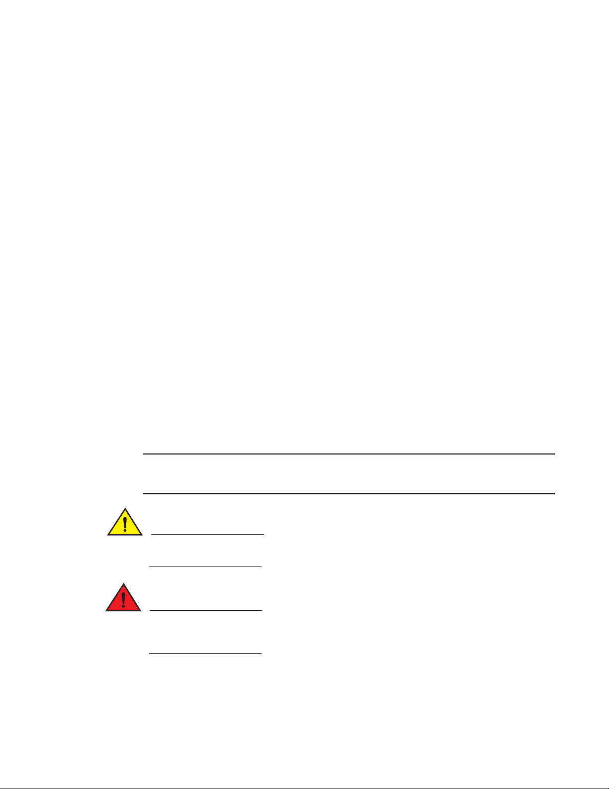
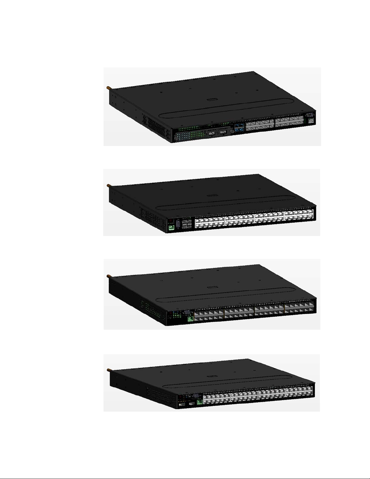
FIGURE 1 Brocade NetIron CES 2000 Series 2024C-4X
FIGURE 2 Brocade NetIron CES 2000 Series 2024F-4X
FIGURE 3 Brocade NetIron CES 2000 Series 2024C
FIGURE 4 Brocade NetIron CES 2000 Series 2024F
2 Brocade NetIron CES 2000 Series and NetIron CER 2000 Series Hardware Installation Guide
53-1003029-02
Page 13
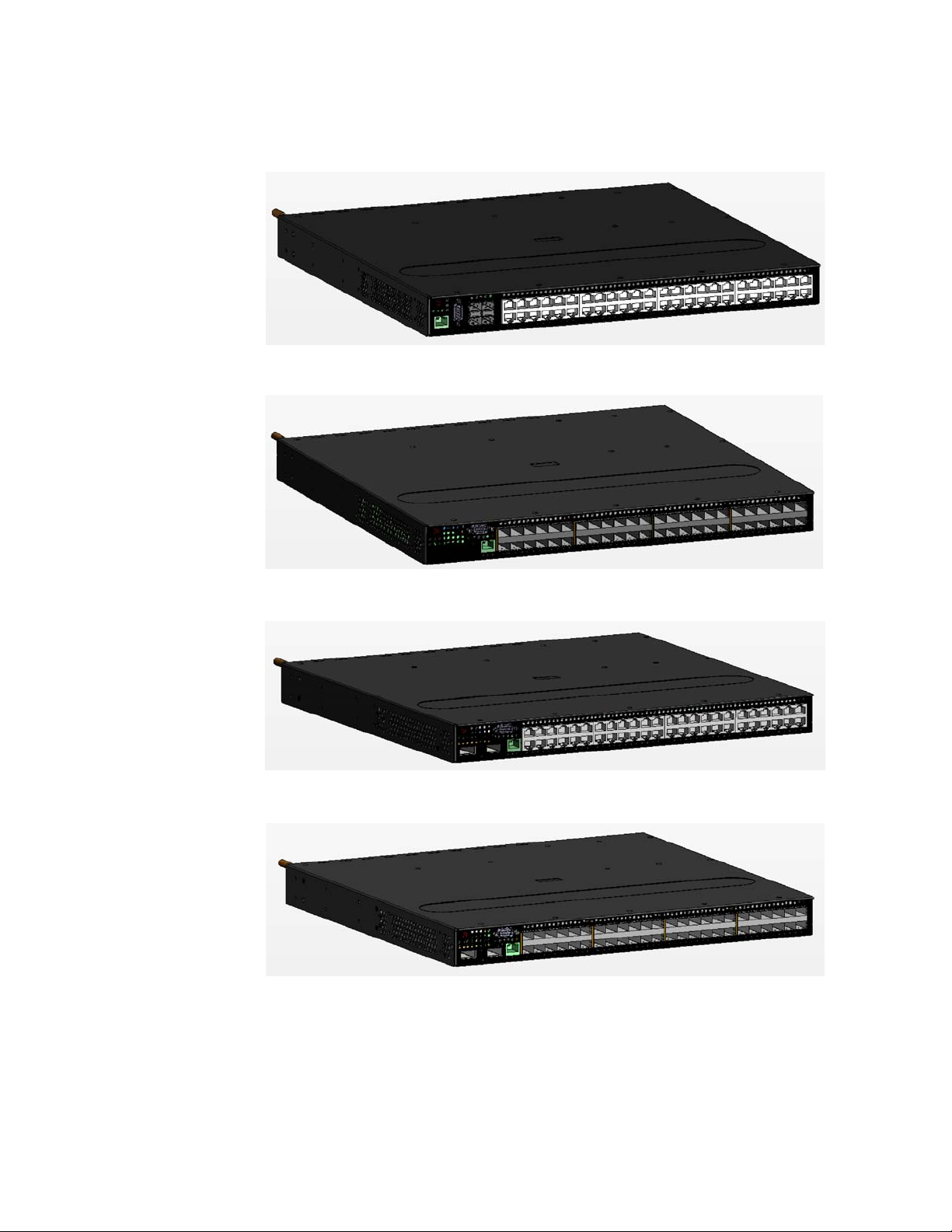
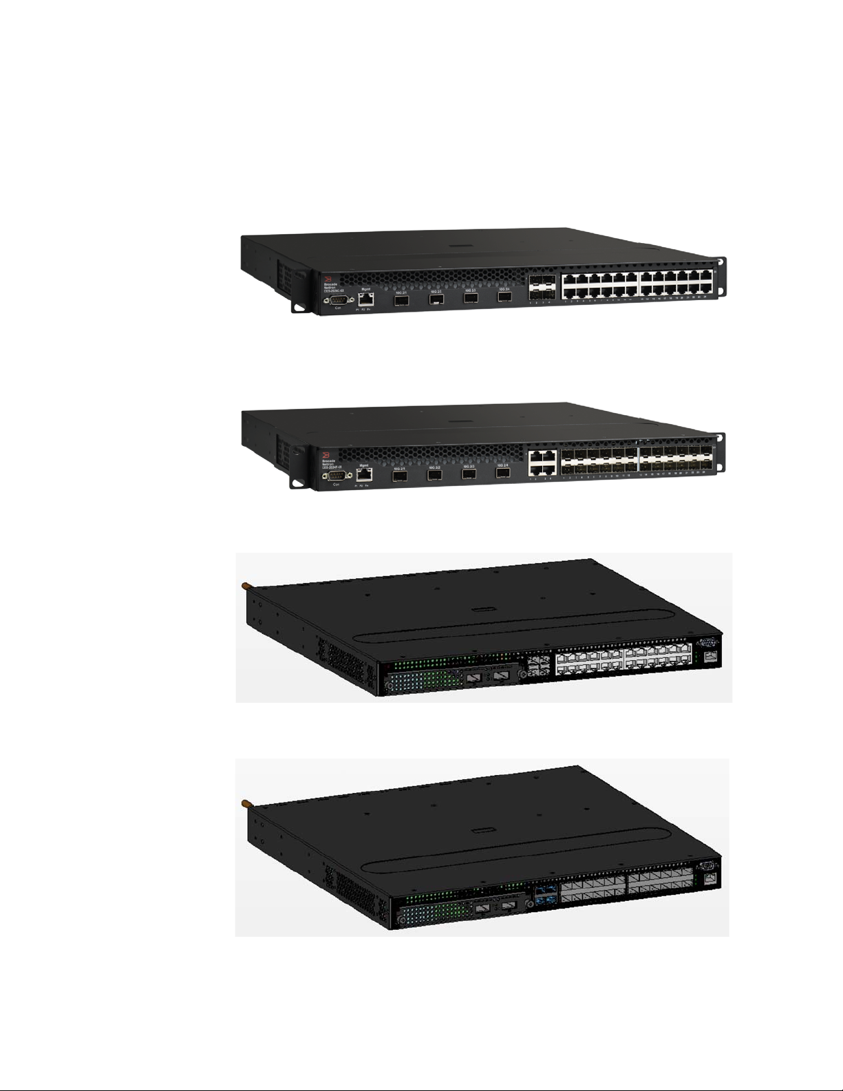
FIGURE 5 Brocade NetIron CES 2000 Series 2048C
FIGURE 6 Brocade NetIron CES 2000 Series 2048F
Introduction
1
FIGURE 7 Brocade NetIron CES 2000 Series 2048CX
FIGURE 8 Brocade NetIron CES 2000 Series 2048FX
There are also fourteen models in the NetIron Carrier Ethernet Router (CER and CER-RT) 2000
Series:
Brocade NetIron CES 2000 Series and NetIron CER 2000 Series Hardware Installation Guide 3
53-1003029-02
Page 14

1
Introduction
• NetIron CER 2000 Series 2024C-4X -RT — accommodates 24-port 10/100/1000 RJ45 model
with 4 combination 100/1000 Hybrid Fiber (HF) ports and 4x10G SFP+ uplinks. This device
has the ability to simultaneously store up to 1.5 million IPv4 routes and up to 256,000 IPv6
routes
• NetIron CER 2000 Series 2024F-4X-RT — accommodates 24-port 100/1000 Hybrid Fiber (HF)
model with 4 combination 10/100/1000 RJ45 ports and 4x10G SFP+ uplinks. This device has
the ability to simultaneously store up to 1.5 million IPv4 routes and up to 256,000 IPv6 routes
• NetIron CER 2000 Series 2024C — accommodates 24-port 10/100/1000 Copper RJ45 model
with 4 combination 100/1000 Hybrid Fiber (HF) ports and an optional field upgradeable
2x10G uplink slot
• NetIron CER 2000 Series- RT 2024C — accommodates 24-port 10/100/1000 Copper RJ45
model with 4 combination 100/1000 Hybrid Fiber (HF) ports and an optional field upgradeable
2x10G uplink slot. This device has the ability to simultaneously store up to 1.5 million IPv4
routes and up to 256,000 IPv6 routes
• NetIron CER 2000 Series 2024F — accommodates 24-port 100/1000 Hybrid Fiber (HF) model
with 4 combination 10/100/1000 RJ45 ports and an optional field upgradeable 2x10G XFP
uplink slot
• NetIron CER 2000 Series- RT 2024F — accommodates 24-port 100/1000 Hybrid Fiber (HF)
model with 4 combination 10/100/1000 RJ45 ports and an optional field upgradeable 2x10G
XFP uplink slot. This device has the ability to simultaneously store up to 1.5 million IPv4 routes
and up to 256,000 IPv6 routes
• NetIron CER 2000 Series 2048C — accommodates 48-port 10/100/1000 Copper RJ45 model
with 4 combination 100/1000 Hybrid Fiber (HF) ports
• NetIron CER 2000 Series- RT 2048C — accommodates 48-port 10/100/1000 Copper RJ45
model with 4 combination 100/1000 Hybrid Fiber (HF) ports. This device has the ability to
simultaneously store up to 1.5 million IPv4 routes and up to 256,000 IPv6 routes
• NetIron CER 2000 Series 2048F — accommodates 48-port 100/1000 Hybrid Fiber (HF) model
• NetIron CER 2000 Series- RT 2048F — accommodates 48-port 100/1000 Hybrid Fiber (HF)
model This device has the ability to simultaneously store up to 1.5 million IPv4 routes and up
to 256,000 IPv6 routes
• NetIron CER 2000 Series 2048CX — accommodates 48-port 10/100/1000 RJ45 model with
2x10G XFP uplink ports
• NetIron CER 2000 Series- RT2048CX — accommodates 48-port 10/100/1000 RJ45 model
with 2x10G XFP uplink ports. This device has the ability to simultaneously store up to 1.5
million IPv4 routes and up to 256,000 IPv6 routes
• NetIron CER 2000 Series 2048FX — accommodates 48-port 100/1000 Hybrid Fiber (HF)
model with 2x10G XFP uplink ports
4 Brocade NetIron CES 2000 Series and NetIron CER 2000 Series Hardware Installation Guide
53-1003029-02
Page 15
Introduction
1
• NetIron CER 2000 Series- RT 2048FX — accommodates 48-port 100/1000 Hybrid Fiber (HF)
model with 2x10G XFP uplink ports. This device has the ability to simultaneously store up to
1.5 million IPv4 routes and up to 256,000 IPv6 routes
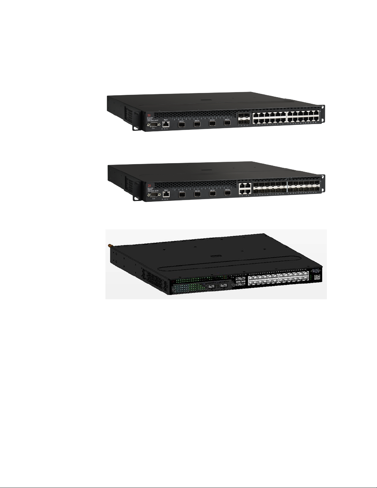
FIGURE 9 NetIron CER 2000 Series 2024C-4X-RT
FIGURE 10 NetIron CER 2000 Series 2024F-4X-RT
FIGURE 11 NetIron CER 2000 Series 2024C
Brocade NetIron CES 2000 Series and NetIron CER 2000 Series Hardware Installation Guide 5
53-1003029-02
Page 16
1
Introduction
FIGURE 12 NetIron CER 2000 Series 2024F
FIGURE 13 NetIron CER 2000 Series 2048C
FIGURE 14 NetIron CER 2000 Series 2048F
FIGURE 15 NetIron CER 2000 Series 2048CX
6 Brocade NetIron CES 2000 Series and NetIron CER 2000 Series Hardware Installation Guide
53-1003029-02
Page 17
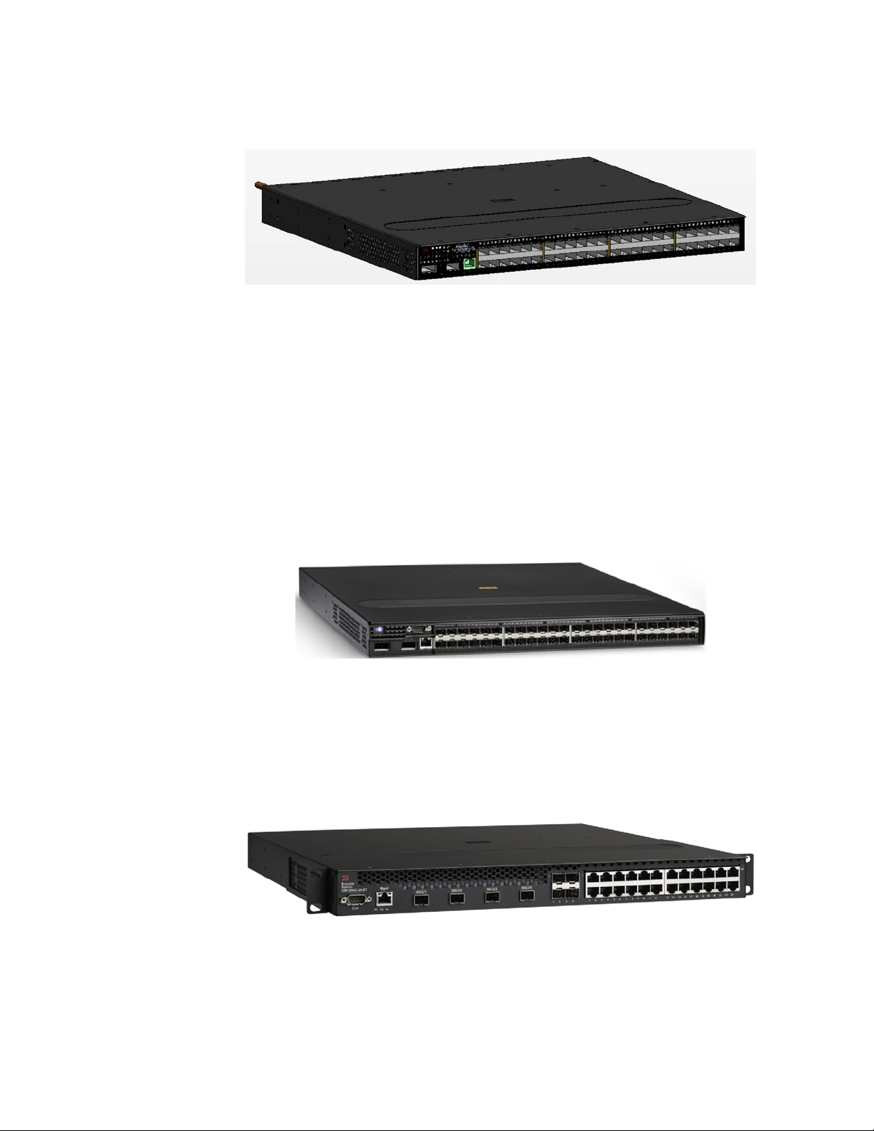
FIGURE 16 NetIron CER 2000 Series 2048FX
Product overview
The Brocade NetIron CES 2000 Series 2000 Series is a compact 1 RU, multi-service edge or
aggregation switch with a powerful set of capabilities that combine performance with rich
functionality at the network edge. The Brocade NetIron CES 2000 Series 2000 Series switch offers
network planners a broad set of high performance IPv4, Classic Layer 2, Provider Bridge (PB) and
Provider Backbone Bridge (PBB) functionalities in the same device. With these capabilities, the
Brocade NetIron CES 2000 Series 2000 Series addresses a diverse set of applications in metro
edge networks, ISP networks, mobile backhaul networks, data centers, large enterprises,
government networks and education or research.
Product overview
1
FIGURE 17 Brocade NetIron CES 2000 Series 2000 Series switch
The NetIron CER 2000 Series 2000 Series is a compact 1 RU, IP, MPLS, and multi-VRF enabled
metro router offering a broad set of capabilities including high performance IPv4 and IPv6 routing,
Advanced Layer 2, Multiprotocol Label Switching (MPLS), Provider Bridge (PB) and Provider
Backbone Bridge (PBB) functionalities in the same device. With these capabilities, the NetIron CER
2000 Series 2000 Series addresses a diverse set of needs in service provider networks and
enterprise applications, as well as metro edge networks and small data centers.
FIGURE 18 NetIron CER 2000 Series 2000 Series router
Brocade NetIron CES 2000 Series and NetIron CER 2000 Series Hardware Installation Guide 7
53-1003029-02
Page 18

Software features
1
Software features
Software features differ depending on the software package that is purchased with the device. The
BASE package on the Brocade NetIron CES 2000 Series 2000 devices support full Layer 2
Switching and base Layer 3 (RIP and static routes). The Metro Edge Premium (ME_PREM) package
support full Layer 2 Switching, base Layer 3 (RIP and static routes), Provider Bridges (IEEE
802.1ad), Provider Backbone Bridges (IEEE 802.1ah), OSPF, ISIS, and Connectivity Fault
Management (IEEE 802.1ag) and Service OAM. The Layer 3 Premium (L3_PREM) packages
support full Layer 2 Switching, base Layer 3 (RIP and static routes), and full Layer 3 including BGP,
ISIS and OSPF.
The BASE package on the NetIron CER 2000 Series 2000 devices support full Layer 2 Switching
and full Layer 3 (RIP, OSPF, ISIS, and BGP). It also includes virtual routing in non-MPLS
environments via Multi-VRF. The Advanced Services Premium (ADV_SVCS_PREM) package includes
MPLS, Layer 2 VPNs using VPLS and VLLs, Provider Bridges (IEEE 802.1ad), Provider Backbone
Bridges (IEEE 802.1ah), Connectivity Fault Management (IEEE 802.1ag) and Service OAM, along
with Ethernet Service Instance (ESI). The Brocade NetIron CER -RT features full MPLS capabilities
as the original Brocade NetIron CER, and has the ability to simultaneously store up to 1.5 million
IPv4 routes and up to 256,000 IPv6 routes.
All Brocade NetIron CES 2000 Series 2000 and NetIron CER 2000 Series 2000 devices can be
upgraded to premium packages.
Upgrade applications
You can convert (upgrade) your Brocade NetIron CES 2000 Series 2000 Series device. Converting
your Brocade NetIron CES 2000 Series 2000 Series device allows you to run a software image that
contains additional capabilities available in premium packages.
To convert your Brocade NetIron CES 2000 Series and NetIron CER 2000 Series 2000 Series
devices, you need an upgrade kit. The kit includes a Dual Inline Package (DIP) key, Multi-Service
IronWare software, upgrade instructions, and other items. Alternatively, you can order an Brocade
NetIron CES 2000 Series or NetIron CER 2000 Series 2000 Series device with the premium
software already installed. For more information, refer to the Multi-Service IronWare Software
Upgrade Guide.
TABLE 2 Upgrade kits
Brocade part number Description
NI-CES-2024-MEU Metro Edge Premium upgrade for Brocade NetIron CES 2000 Series 2000
NI-CES-2024-L3U L3 Premium upgrade for Brocade NetIron CES 2000 Series 2000 Series
NI-CES-2048-MEU Metro Edge Premium upgrade for Brocade NetIron CES 2000 Series 2000
NI-CES-2048-L3U L3 Premium upgrade for Brocade NetIron CES 2000 Series 2000 Series
NI-CER-2024-ADVU Advanced Services Premium License for NetIron CER 2000 Series 24-port
NI-CER-2048-ADVU Advanced Services Premium License for NetIron CER 2000 Series 48-port
Series 24-port models.
24-port models.
Series 48-port models.
48-port models.
models.
models.
8 Brocade NetIron CES 2000 Series and NetIron CER 2000 Series Hardware Installation Guide
53-1003029-02
Page 19
Hardware features
NOTE
This section describes the physical characteristics of the Brocade NetIron CES 2000 Series 2000
and NetIron CER 2000 Series 2000 Series devices. For details about physical dimensions, power
supply specifications, and pinouts, refer to the “Hardware specifications” on page 59.
The following figures show the front panels of the various NetIron 2024 and 2048 devices.
This is only a representative sample. For the exact model, look at the faceplate on the front of the
device. Both CER and CES devices have similar look and feel.
Brocade NetIron CES 2000 Series 2024C-4X
The Brocade NetIron CES 2000 Series 2024C-4X switch has twenty-four 10/100/1000 MbE RJ45
ports plus four combination 100/ 1000 MbE SFP ports, 4-port 10 GbE SFP+ module, one DB9
serial management interface port labeled Console, one 10/100/1000 MbE RJ45 out-of-band
management port, one resilient six-unit fan tray, and two AC power supply bays for 1+1 redundancy
with one 500W AC power supply included.
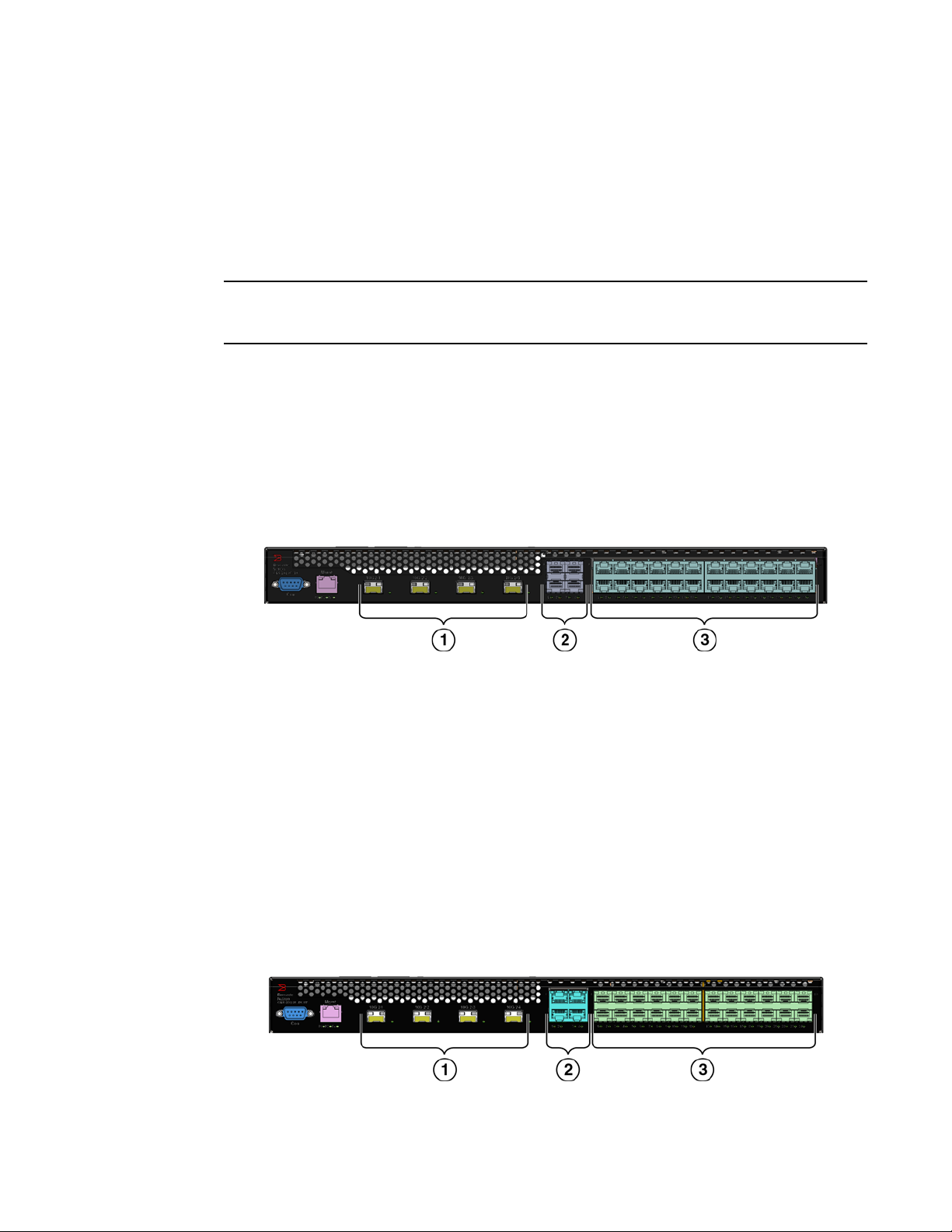
FIGURE 19 Brocade NetIron CES 2000 Series 2024C-4X device
Hardware features
1
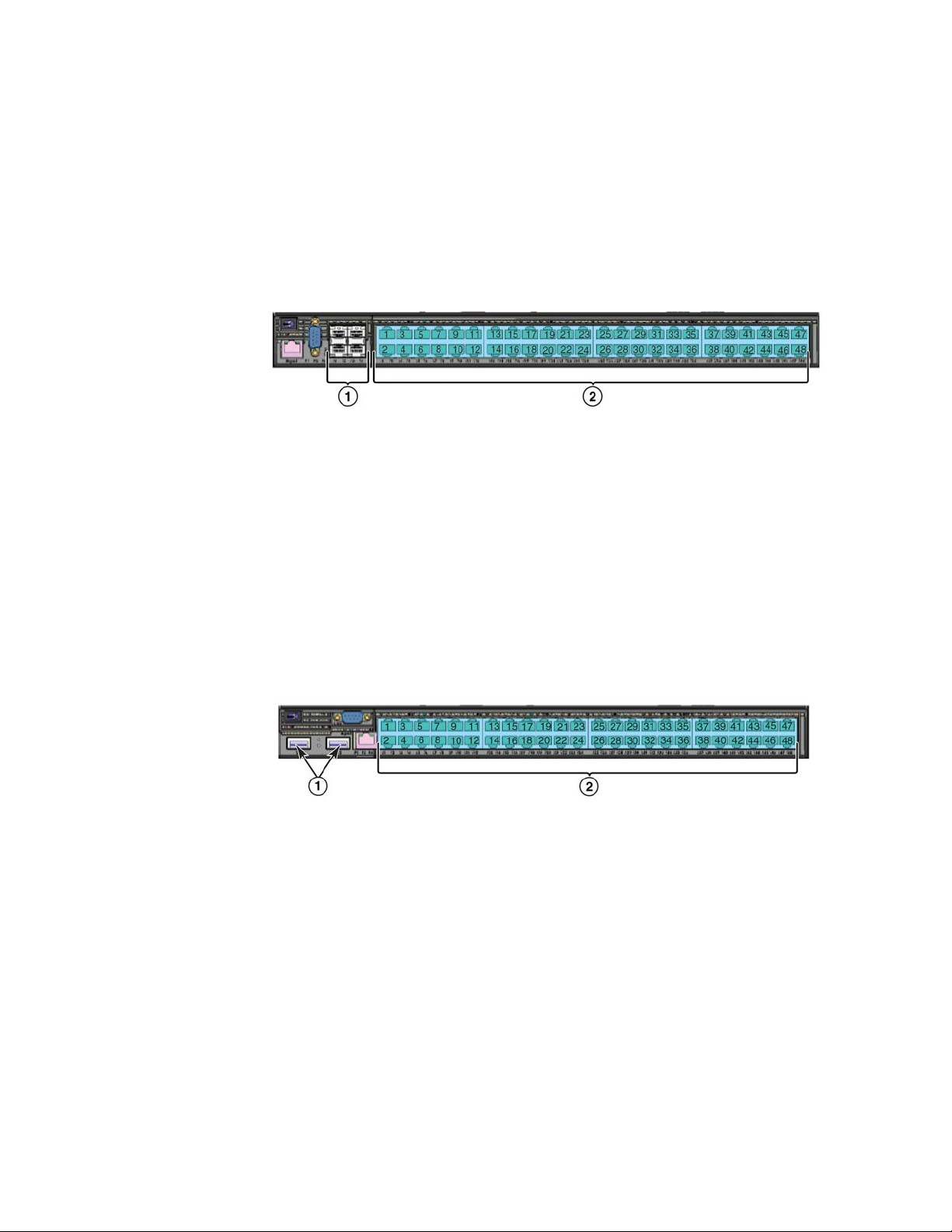
Brocade NetIron CES 2000 Series 2024F-4X
110 GbE SFP+ ports
2 Four combination 100/1000 MbE SFP ports
3 Twenty-four 10/100/1000 MbE RJ45 ports
The Brocade NetIron CES 2000 Series 2024F-4X has twenty-four 100/1000 MbE SFP ports plus
four combination 10/100/1000 MbE RJ45 ports, 4-port 10 GbE SFP+ module, one DB9 serial
management interface port labeled Console, one 10/100/1000 MbE RJ45 out-of-band
management port, one resilient six-unit fan tray, and two AC power supply bays for 1+1 redundancy
with one 500W AC power supply included.
FIGURE 20 Brocade NetIron CES 2000 Series 2024F-4X device
Brocade NetIron CES 2000 Series and NetIron CER 2000 Series Hardware Installation Guide 9
53-1003029-02
Page 20
Hardware features
1
110 GbE SFP+ ports
2 Four combination 10/100/1000 MbE RJ45 ports
3 Twenty-four 100/1000 MbE SFP ports
Brocade NetIron CES 2000 Series 2024C
The Brocade NetIron CES 2000 Series 2024C switch has twenty-four 10/100/1000 MbE RJ45
ports plus four combination 100/ 1000 MbE SFP ports, one module slot for an optional field
upgradable 2-port 10 GbE XFP module, one DB9 serial management interface port labeled
Console, one 10/100/1000 MbE RJ45 out-of-band management port, one resilient six-unit fan
tray, and two AC power supply bays for 1+1 redundancy with one 500W AC power supply included.
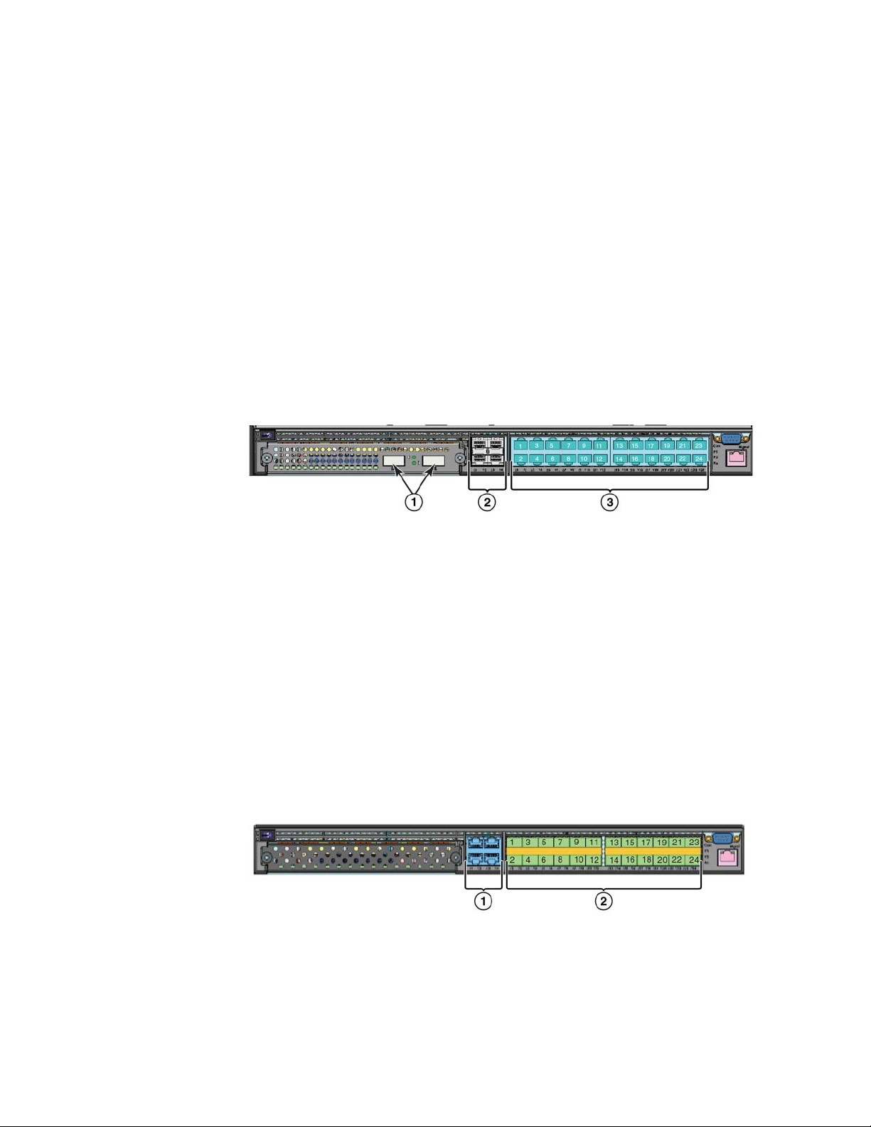
FIGURE 21 Brocade NetIron CES 2000 Series 2024C device with the optional 2 ports of 10-G XFP
uplink
1 Optional 10 GbE XFP ports
2 Four combination 100/1000 MbE SFP ports
3 Twenty-four 10/100/1000 MbE RJ45 ports
Brocade NetIron CES 2000 Series 2024F
The Brocade NetIron CES 2000 Series 2024F has twenty-four 100/1000 MbE SFP ports plus four
combination 10/100/1000 MbE RJ45 ports, one module slot for an optional field upgradable
2-port 10 GbE XFP module, one DB9 serial management interface port labeled Console, one
10/100/1000 MbE RJ45 out-of-band management port, one resilient six-unit fan tray, and two AC
power supply bays for 1+1 redundancy with one 500W AC power supply included.
FIGURE 22 Brocade NetIron CES 2000 Series 2024F device
1 Four combination 10/100/1000 MbE RJ45 ports with support for optional 10Gbe XFP ports
2 Twenty-four 100/1000 MbE SFP ports
10 Brocade NetIron CES 2000 Series and NetIron CER 2000 Series Hardware Installation Guide
53-1003029-02
Page 21
Hardware features
1
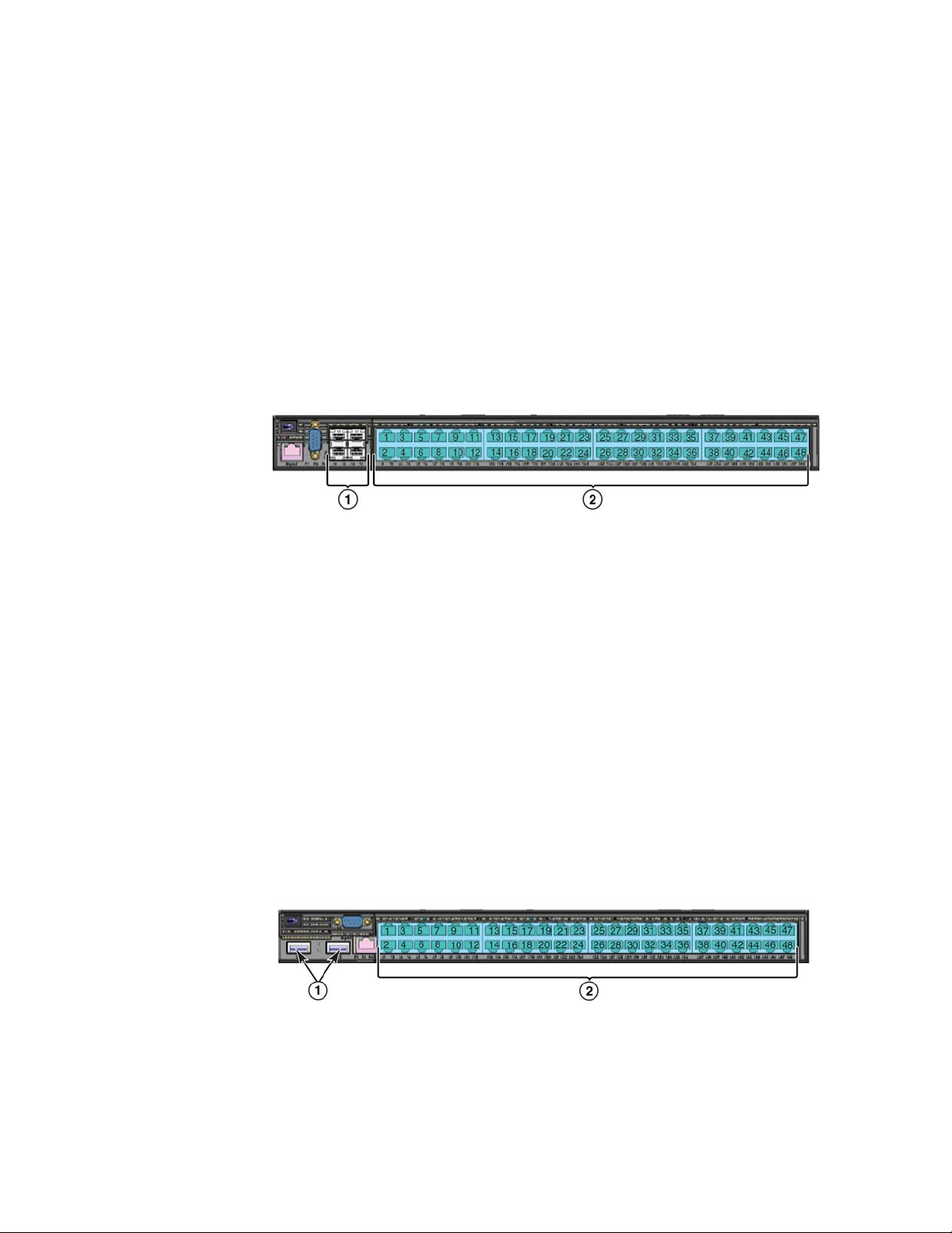
Brocade NetIron CES 2000 Series 2048C
Brocade NetIron CES 2000 Series 2048C (Copper) switch has forty-eight 10/100/1000 MbE RJ45
ports plus four combination 100/ 1000 MbE SFP ports, one DB9 serial management interface port
labeled Console, one 10/100/1000 MbE RJ45 out-of-band management port, one resilient six-unit
fan tray, and two AC power supply bays for 1+1 redundancy with one 500W AC power supply
included
FIGURE 23 Brocade NetIron CES 2000 Series 2048C device
1 Four combination 100/1000 MbE SFP ports
2 Forty-eight 10/100/1000 MbE RJ45 ports
.
Brocade NetIron CES 2000 Series 2048CX
Brocade NetIron CES 2000 Series 2048CX (Copper) has forty-eight 10/100/1000 MbE RJ45 ports
plus two 10 GbE XFP ports, one DB9 serial management interface port labeled Console, one
10/100/1000 MbE RJ45 out-of-band management port, one resilient six-unit fan tray, and two AC
power supply bays for 1+1 redundancy with one 500W AC power supply included.
FIGURE 24 Brocade NetIron CES 2000 Series 2048CX device
110 GbE XFP ports
2 Forty-eight 10/100/1000 MbE RJ45 ports
Brocade NetIron CES 2000 Series and NetIron CER 2000 Series Hardware Installation Guide 11
53-1003029-02
Page 22
Hardware features
1
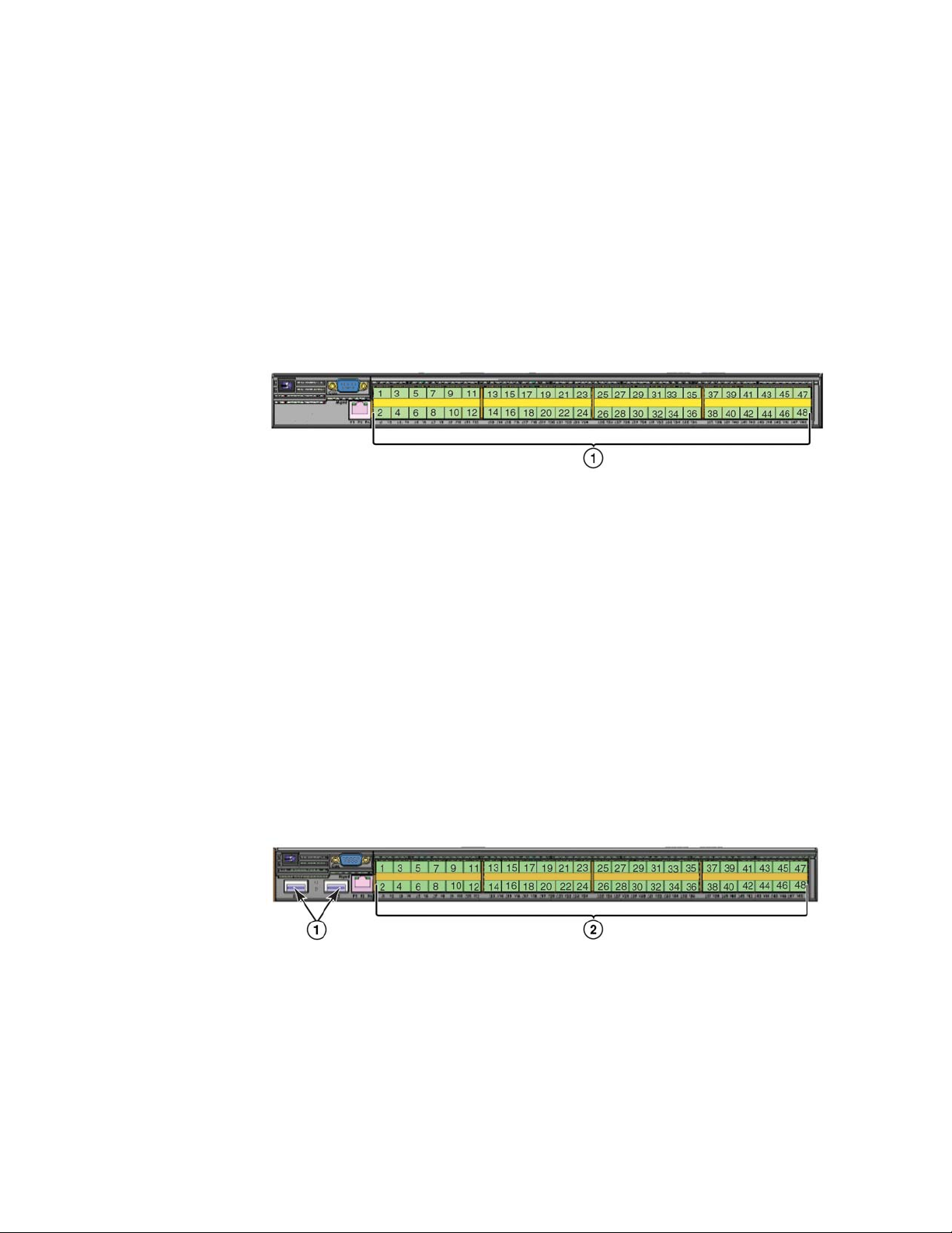
Brocade NetIron CES 2000 Series 2048F
Brocade NetIron CES 2000 Series 2048F (Fiber) has forty-eight 100/1000 MbE SFP ports, one
DB9 serial management interface port labeled Console, one 10/100/1000 MbE RJ45 out-of-band
management port, one resilient six-unit fan tray, and two AC power supply bays for 1+1 redundancy
with one 500W AC power supply included.
FIGURE 25 Brocade NetIron CES 2000 Series 2048F device
1 Forty eight 100/1000 MbE SFP ports
Brocade NetIron CES 2000 Series 2048FX
Brocade NetIron CES 2000 Series 2048FX (Fiber) switch has forty-eight 100/1000 MbE SFP ports
plus two 10 GbE XFP ports, one DB9 serial management interface port labeled Console, one
10/100/1000 MbE RJ45 out-of-band management port, one resilient six-unit fan tray, and two AC
power supply bays for 1+1 redundancy with one 500W AC power supply included.
FIGURE 26 Brocade NetIron CES 2000 Series 2048FX device
110 GbE XFP ports
2 Forty eight 100/1000 MbE SFP ports
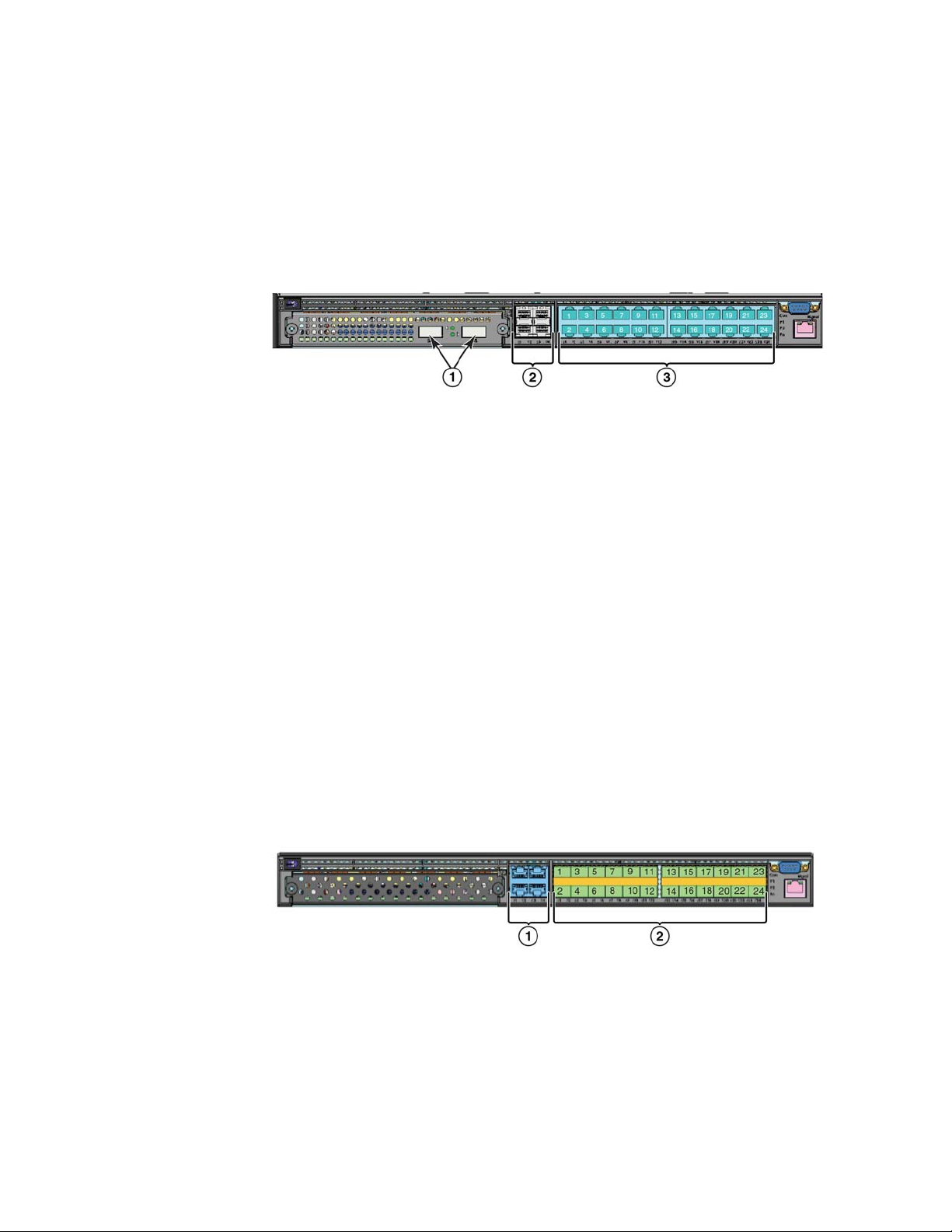
NetIron CER 2000 Series 2024C
The NetIron CER 2000 Series 2024C router has twenty-four 10/100/1000 MbE RJ45 ports plus
four combination 100/ 1000 MbE SFP ports, one module slot for an optional field upgradable
2-port 10 GbE XFP module, one DB9 serial management interface port labeled Console, one
10/100/1000 MbE RJ45 out-of-band management port, one resilient six-unit fan tray, and two AC
power supply bays for 1+1 redundancy with one 500W AC power supply included.
12 Brocade NetIron CES 2000 Series and NetIron CER 2000 Series Hardware Installation Guide
53-1003029-02
Page 23
Hardware features
The NetIron CER 2000 Series-RT 2024C router has more memory to support 1.5M routes,
twenty-four 10/100/1000 MbE RJ45 ports plus four combination 100/ 1000 MbE SFP ports, one
module slot for an optional field upgradable 2-port 10 GbE XFP module, one DB9 serial
management interface port labeled Console, one 10/100/1000 MbE RJ45 out-of-band
management port, one resilient six-unit fan tray, and two AC power supply bays for 1+1 redundancy
with one 500W AC power supply included.
1
FIGURE 27 NetIron CER 2000 Series 2024C device with the optional 2 ports of 10-G XFP uplink
1 Optional 10 GbE XFP ports
2 Four combination 100/1000 MbE SFP ports
3 Twenty-four 10/100/1000 MbE RJ45 ports
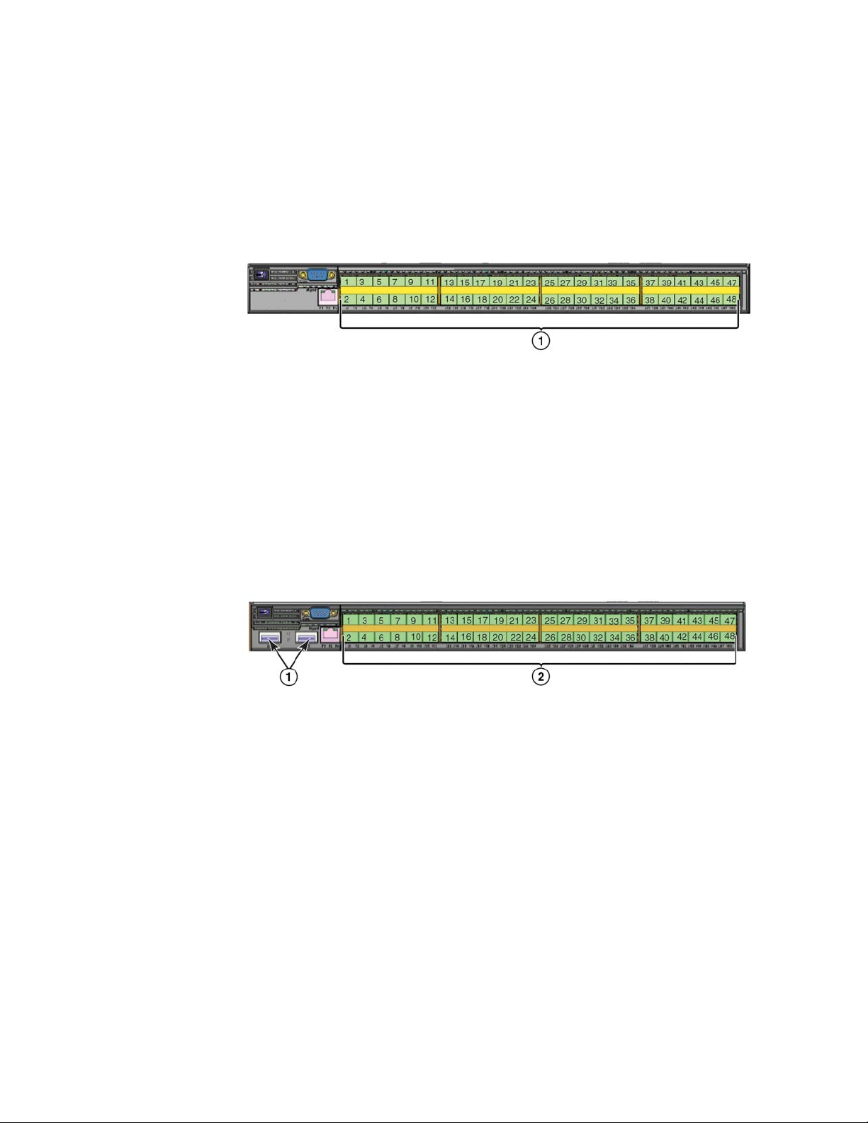
NetIron CER 2000 Series 2024F
The NetIron CER 2000 Series 2024F has twenty-four 100/1000 MbE SFP ports plus four
combination 10/100/1000 MbE RJ45 ports, one module slot for an optional field upgradable
2-port 10 GbE XFP module, one DB9 serial management interface port labeled Console, one
10/100/1000 MbE RJ45 out-of-band management port, one resilient six-unit fan tray, and two AC
power supply bays for 1+1 redundancy with one 500W AC power supply included.
The NetIron CER 2000 Series-RT 2024F has more memory to support 1.5M routes, twenty-four
100/1000 MbE SFP ports plus four combination 10/100/1000 MbE RJ45 ports, one module slot
for an optional field upgradable 2-port 10 GbE XFP module, one DB9 serial management interface
port labeled Console, one 10/100/1000 MbE RJ45 out-of-band management port, one resilient
six-unit fan tray, and two AC power supply bays for 1+1 redundancy with one 500W AC power supply
included.
FIGURE 28 NetIron CER 2000 Series 2024F device
1 Four combination 10/100/1000 MbE RJ45 ports with support for optional 10Gbe XFP ports
2 Twenty-four 100/1000 MbE SFP ports.
Brocade NetIron CES 2000 Series and NetIron CER 2000 Series Hardware Installation Guide 13
53-1003029-02
Page 24
Hardware features
1
NetIron CER 2000 Series 2048C
NetIron CER 2000 Series 2048C (Copper) router has forty-eight 10/100/1000 MbE RJ45 ports
plus four combination 100/ 1000 MbE SFP ports, one DB9 serial management interface port
labeled Console, one 10/100/1000 MbE RJ45 out-of-band management port, one resilient six-unit
fan tray, and two AC power supply bays for 1+1 redundancy with one 500W AC power supply
included
NetIron CER 2000 Series-RT 2048C (Copper) router has more memory to support 1.5M routes,
forty-eight 10/100/1000 MbE RJ45 ports plus four combination 100/ 1000 MbE SFP ports, one
DB9 serial management interface port labeled Console, one 10/100/1000 MbE RJ45 out-of-band
management port, one resilient six-unit fan tray, and two AC power supply bays for 1+1 redundancy
with one 500W AC power supply included
FIGURE 29 NetIron CER 2000 Series 2048C device
.
.
1 Four combination 100/1000 MbE SFP ports
2 Forty-eight 10/100/1000 MbE RJ45 ports
NetIron CER 2000 Series 2048CX
NetIron CER 2000 Series 2048CX (Copper) has forty-eight 10/100/1000 MbE RJ45 ports plus two
10 GbE XFP ports, one DB9 serial management interface port labeled Console, one 10/100/1000
MbE RJ45 out-of-band management port, one resilient six-unit fan tray, and two AC power supply
bays for 1+1 redundancy with one 500W AC power supply included.
NetIron CER 2000 Series-RT 2048CX (Copper) has more memory to support 1.5M routes,
forty-eight 10/100/1000 MbE RJ45 ports plus two 10 GbE XFP ports, one DB9 serial management
interface port labeled Console, one 10/100/1000 MbE RJ45 out-of-band management port, one
resilient six-unit fan tray, and two AC power supply bays for 1+1 redundancy with one 500W AC
power supply included.
FIGURE 30 NetIron CER 2000 Series 2048CX device
110 GbE XFP ports
2 Forty-eight 10/100/1000 MbE RJ45 ports
14 Brocade NetIron CES 2000 Series and NetIron CER 2000 Series Hardware Installation Guide
53-1003029-02
Page 25
Hardware features
1
NetIron CER 2000 Series 2048F
NetIron CER 2000 Series 2048F (Fiber) has forty-eight 100/1000 MbE SFP ports, one DB9 serial
management interface port labeled Console, one 10/100/1000 MbE RJ45 out-of-band
management port, one resilient six-unit fan tray, and two AC power supply bays for 1+1 redundancy
with one 500W AC power supply included.
NetIron CER 2000 Series-RT 2048F (Fiber) has more memory to support 1.5M routes, forty-eight
100/1000 MbE SFP ports, one DB9 serial management interface port labeled Console, one
10/100/1000 MbE RJ45 out-of-band management port, one resilient six-unit fan tray, and two AC
power supply bays for 1+1 redundancy with one 500W AC power supply included.
FIGURE 31 NetIron CER 2000 Series 2048F device
1 Forty eight 100/1000 MbE SFP ports
NetIron CER 2000 Series 2048FX
NetIron CER 2000 Series 2048FX (Fiber) router has forty-eight 100/1000 MbE SFP ports plus two
10 GbE XFP ports, one DB9 serial management interface port labeled Console, one 10/100/1000
MbE RJ45 out-of-band management port, one resilient six-unit fan tray, and two AC power supply
bays for 1+1 redundancy with one 500W AC power supply included.
NetIron CER 2000 Series-RT 2048FX (Fiber) router has more memory to support to support 1.5M
routes, forty-eight 100/1000 MbE SFP ports plus two 10 GbE XFP ports, one DB9 serial
management interface port labeled Console, one 10/100/1000 MbE RJ45 out-of-band
management port, one resilient six-unit fan tray, and two AC power supply bays for 1+1 redundancy
with one 500W AC power supply included.
FIGURE 32 NetIron CER 2000 Series 2048FX device
110 GbE XFP ports
2 Forty eight 100/1000 MbE SFP ports
Brocade NetIron CES 2000 Series and NetIron CER 2000 Series Hardware Installation Guide 15
53-1003029-02
Page 26

Hardware features
1
Control features
The front panel on each device has a combination of the following control features:
• Serial Management Interface (the port labeled Console)
• 10/100/1000 ports with RJ-45 copper connectors
• 100/1000 Hybrid Fiber (HF) ports
• 100/1000 ports with mini-GBIC slots for SFP MSA-compliant fiber transceivers
• Each device that optionally has up to two 10-Gigabit Ethernet uplink ports, supports 10-Gigabit
Small Form Factor Pluggable (XFP) MSA-compliant optical transceivers
• Each device that has four 10-Gigabit Ethernet uplink ports, supports 10-Gigabit Small Form
Factor Pluggable (SFP+) MSA-compliant optical transceivers
Serial Management Interface (console port)
The Serial Management Interface enables you to configure and manage the device using a
third-party terminal emulation application on a directly connected PC. A straight-through EIA/TIA
DB-9 serial cable (M/F) ships with the device. The serial management interface (the port labeled
Console) is located in the front panel.
Port LEDs
The ports on the devices provide status information using the LEDs listed in Table 3 and Tab le 4.
TABLE 3 LEDs for 10/100/1000 Mbps ports
LED Position State Meaning
10/100/1000 Port LEDs
Lnk/Act Bottom Left On Link is up.
Off Link is down.
Blinking Port is transmitting or receiving traffic
Lnk/Act Bottom Right On Link is up.
Off Link is down.
Blinking Port is transmitting or receiving traffic
NOTE: The LEDs are located beneath the port connector.
16 Brocade NetIron CES 2000 Series and NetIron CER 2000 Series Hardware Installation Guide
53-1003029-02
Page 27

Hardware features
TABLE 4 LEDs for 10-Gbps Ethernet ports
LED Port State Meaning
10-Gbps Port LEDs on devices with two 10-Gbps ports
Top Left hand port On The port is connected.
Off No fiber port connection exists.
Blinking Traffic is being transmitted and received on the
fiber port
Bottom Right hand port On The port is connected.
Off No fiber port connection exists.
Blinking Traffic is being transmitted and received on the
fiber port
10-Gbps Port LEDs on devices with four 10-Gbps ports
Top Left hand port On The port is connected.
Off No fiber port connection exists.
Blinking Traffic is being transmitted and received on the
fiber port
Bottom Right hand port On The port is connected.
Off No fiber port connection exists.
Blinking Traffic is being transmitted and received on the
fiber port
NOTE: The LEDs are located adjacent to the port connector.
1
Network interfaces
This section describes the port types in the Brocade NetIron CES 2000 Series, NetIron CER 2000
Series 2000 series devices.
10/100/1000 Mbps ports
The 10/100/1000 ports on the device use auto-sensing and auto-negotiating to determine the
speed (10 Mbps, 100 Mbps, or 1000 Mbps) and duplex mode (full-duplex or half-duplex) of the port
at the other end of the link and adjust port speed accordingly.
Combination ports
On devices with combination (combo) ports, one port out of each pair of copper and fiber ports can
be active at a time. Combo ports are numbered 1-4. For example, you can use either copper port 2
or fiber port 2, but not both at the same time. You can use a combination of fiber and copper ports
or all copper or all fiber ports, as needed.
If you attach both the copper and fiber connectors for a port to the network, the fiber connectors
take precedence over the copper connectors. These ports support true media automatic detection,
meaning the device selects the fiber or copper connector based on link availability. If a fiber link
cannot be established, the device selects the copper media.
Brocade NetIron CES 2000 Series and NetIron CER 2000 Series Hardware Installation Guide 17
53-1003029-02
Page 28

Hardware features
1
10-Gbps ports
The Brocade NetIron CES 2000 Series 2048C-4X, Brocade NetIron CES 2000 Series 2048F-4X,
NetIron CER 2000 Series 2048C-4X-RT, and the NetIron CER 2000 Series 2048F-4X-RT come with
four 10-Gigabit Ethernet ports installed. The four 10-Gigabit Ethernet uplink ports support
10-Gigabit Small Form Factor Pluggable (SFP+) MSA-compliant optical transceivers
The Brocade NetIron CES 2000 Series 2048CX, Brocade NetIron CES 2000 Series 2048FX,
NetIron CER 2000 Series 2048CX, and the NetIron CER 2000 Series 2048FX come with two
10-Gigabit Ethernet ports installed. A 24-port Brocade NetIron CES 2000 Series,NetIron CER 2000
Series has a slot to accommodate a 2-port 10-Gigabit Ethernet module. If your 24-port device does
not include a 10-GbE module, you can optionally install one. Refer to “10-Gigabit Ethernet module
installation or replacement” on page 80. The two 10-Gigabit Ethernet ports use 10-Gigabit Small
Form Factor Pluggable (XFP) MSA-compliant transceivers.
Supported optics
100/1000 Ethernet Ports
The Ethernet Interface module contains 24 or 48 physical ports, through which you can connect
your device to other network devices at a speed of 100 Mbps or 1 Gbps.
Into a physical port, you must insert a fiber-optic transceiver provided by Brocade. The
SFP-compliant fiber-optic modules provide an optical transceiver or physical medium-dependent
(PMD) interface for fiber that can be used with the LAN physical layer (PHY)
The following 100 Mbps and 1 GbE optical transceivers are available from Brocade:
TABLE 5 SFP-compliant transceivers for the 100/1000 Ethernet interface module
Part number Description
E1MG-TX SFP Copper, RJ-45 connector
E1MG-SX 1000Base-SX SFP optic, multi-mode fiber, LC connector
E1MTG-SX 1000Base-SX SFP optic, multi-mode fiber, MTRJ connector
E1MG-SX2-1310 1310 1000Base-SX SFP optic multi-mode fiber, LC connector and support for distances
up to 2km
E1MG-LX 1000Base-LX SFP optic, single-mode fiber, LC connector
E1MG-LHA 1000Base-LHA SFP optic, single-mode fiber, LC connector
E1MG-LHB 1000Base-LHB SFP optic, single-mode fiber, LC connector, 150km Maximum Reach
E1MG-BXD 1000Base-BXD SFP optic single-mode fiber, 1490nm, LC connector.
This optic can only be connected to an E1MG-BXU
E1MG-CWDM80-1470 CWDM SFP optic, 80km, 1470nm, LC connector
E1MG-CWDM80-1490 CWDM SFP optic, 80Km, 1490nm, LC connector
E1MG-CWDM80-1510 CWDM SFP optic, 80Km, 1510nm, LC connector
E1MG-CWDM80-1530 CWDM SFP optic, 80Km, 1530nm, LC connector
E1MG-CWDM80-1550 CWDM SFP optic, 80Km, 1550nm, LC connector
E1MG-CWDM80-1570 CWDM SFP optic, 80Km, 1570nm, LC connector
E1MG-CWDM80-1590 CWDM SFP optic, 80Km, 1590nm, LC connector
E1MG-CWDM80-1610 CWDM SFP optic, 80Km, 1610nm, LC connector
18 Brocade NetIron CES 2000 Series and NetIron CER 2000 Series Hardware Installation Guide
53-1003029-02
Page 29

Hardware features
1
TABLE 5 SFP-compliant transceivers for the 100/1000 Ethernet interface module (Continued)
Part number Description
E1MG-100FX 100Base-FX SFP optic multi-mode fiber, LC connector
E1MG-100BXU 100Base-BXU SFP optic single-mode fiber, 1310nm, LC connector.
This optic can only be connected to an E1MG-100BXD.
E1MG-100BXD 100Base-BXD SFP optic single-mode fiber, 1490nm, LC connector.
This optic can only be connected to an E1MG-100BXU.
E1MG-100FX-IR 100BaseFX-IR optic for SMF with LC connector. For distances up to 15nm.
E1MG-100FX-LR 100BaseFX-LR SFP optic for SMF with LC connector. For distances up to 40km.
10 Gigabit Ethernet ports
A 10 Gigabit Ethernet module contains two or four physical ports, through which you can connect
your device to other network devices at a speed of 10 Gigabits.
Into a physical port, you must insert a fiber-optic transceiver provided by device. The
XFP/SFP+-compliant fiber-optic modules provide an optical transceiver or physical
medium-dependent (PMD) interface for single or multi-mode fiber that can be used with the LAN
physical layer (PHY).
The following 10 Gigabit optics are available from device.
TABLE 6 MSA-compliant Optics for the 10 GbE Ethernet interface module
Part number Description
Devices with up to two 10GbE ports (XFP)
10G-XFP-SR 850nm serial pluggable XFP optic, target range 300m over multi-mode fiber
10G-XFP-LR 1310nm serial pluggable XFP optic for up to 10km over single-mode fiber
10G-XFP-ER 1550nm serial pluggable XFP optic for up to 40km over single-mode fiber
10G-XFP-ZR 1550nm serial pluggable XFP optic for up to 80km over single-mode fiber
10G-XFP-ZRD 10GBase-ZR DWDM, XFP optic, 80km, 1530.33 to 1561.42
10G-XFP-CX4 10-Base-CX4, XFP transceiver, 15km, CX connector
Devices with up to four 10GbE ports (SFP+)
10G-SFPlus-SR
10G-SFPlus-LR
10G-SFPlus-ZR
10G-SFPlus-ZRD
Port regions
Ports on the devices are grouped into regions. For a few features, such as port monitoring and
unknown unicast configurations, you will need to know the region to which a port belongs. However,
for most features, a port’s region does not affect configuration or operation of the feature. If a
port’s region does affect configuration or operation of a feature, it is noted and described in the
appropriate feature section of this guide.
Brocade NetIron CES 2000 Series 2024 and CER 2024 devices with 24 ports have 2 optional
10-GbE ports:
Brocade NetIron CES 2000 Series and NetIron CER 2000 Series Hardware Installation Guide 19
53-1003029-02
Page 30

Hardware features
1
• Ports 1/1 – 1/24
• Port 2/1 (optional 10-GbE uplink port)
• Port 2/2 (optional 10-GbE uplink port)
• Port 2/3 (optional 10-GbE uplink port)
• Port 2/4 (optional 10-GbE uplink port)
Brocade NetIron CES 2000 Series 2048 and NetIron CER 2000 Series 2048 devices with 48 ports:
• Ports 1/1 –1/24
• Ports 1/25 – 1/48
• Port 2/1 (10-GbE uplink port on Brocade NetIron CES 2000 Series 2048CX, Brocade NetIron
CES 2000 Series 2048FX, NetIron CER 2000 Series 2048CX, and NetIron CER 2000 Series
2048FX models only)
• Port 2/2 (10-GbE uplink port on Brocade NetIron CES 2000 Series 2048CX, Brocade NetIron
CES 2000 Series 2048FX, NetIron CER 2000 Series 2048CX, and NetIron CER 2000 Series
2048FX models only)
• Port 2/3 (10-GbE uplink port on Brocade NetIron CES 2000 Series 2048CX, Brocade NetIron
CES 2000 Series 2048FX, NetIron CER 2000 Series 2048CX, and NetIron CER 2000 Series
2048FX models only)
• Port 2/4 (10-GbE uplink port on Brocade NetIron CES 2000 Series 2048CX, Brocade NetIron
CES 2000 Series 2048FX, NetIron CER 2000 Series 2048CX, and NetIron CER 2000 Series
2048FX models only)
Brocade NetIron CES 2000 Series 2024x and NetIron CER 2000 Series 2024x devices with 24
ports have 2 optional 10-G ports:
• Ports 1/1 –1/24
• Port 2/1 (10G uplink port)
• Port 2/2 (10G uplink port)
• Port 2/3 (10G uplink port)
• Port 2/4 (10G uplink port)
Network interfaces
The output of the show media command displays the type of media installed in the ports.
Brocade# show media
Port 1/1:
Type : Copper
Vendor: Unknown, Version: Unknown
Part# : Unknown, Serial#: Unknown
Port 1/2:
Type : Copper
Vendor: Unknown, Version: Unknown
Part# : Unknown, Serial#: Unknown
Port 1/24:
Type : Copper
Vendor: , Version: Unknown
Part# : Unknown, Serial#: Unknown
Port 2/1:
Type : 10GBASE-SR/SW (XFP)
Vendor: FOUNDRY NETWORKS, Version: 00
20 Brocade NetIron CES 2000 Series and NetIron CER 2000 Series Hardware Installation Guide
53-1003029-02
Page 31

Hardware features
NOTE
Part# : FTLX8511D3-F1 , Serial#: KCP02X8
Port 2/2:
Type : 10GBASE-SR/SW (XFP)
Vendor: FOUNDRY NETWORKS, Version: 02
Part# : TRF2000EN-LF251 , Serial#: T07J23170
All show media done
Syntax: show media
1
Power supplies
Each device comes with one alternating-current (AC) or one direct-current (DC) power supply. All
models have two power supply slots, enabling you to install a second power supply for redundancy.
Changes or modifications made to this device that are not expressly approved by the party
responsible for compliance could void the user's authority to operate the equipment.
The power supplies can be swapped in or out of the device while the device is running. You can
remove and insert a power supply without opening the chassis. The remaining supply provides
enough power for the entire system.
The following sections provide further details about the power supplies for the devices:
• Power status LEDs are listed in “Observing the power status LEDs” on page 47.
• Hardware specifications for the power supplies are listed in “Hardware specifications” on
page 59.
• “About redundant power supplies and power supply failure” on page 22
AC power supplies
Figure 33 shows a rear view of a device containing one AC power supply.
FIGURE 33 AC Power Supply
1Power supply
2 Six cooling fans
Brocade NetIron CES 2000 Series and NetIron CER 2000 Series Hardware Installation Guide 21
53-1003029-02
Page 32

Hardware features
NOTE
1
DC power supplies
Figure 34 shows the DC power supply.
FIGURE 34 DC Power Supply
About redundant power supplies and power supply failure
A device with redundant power supplies can maintain full operation when one power supply fails.
Power supply failure can be a failure of the supply itself or the power grid connected to the power
supply.
Cooling system and fans
This section describes the fans in the devices with 6 fans.
Figure 35 shows the cooling fans.
FIGURE 35 Cooling Fans
1 Six cooling fans
The device cooling fans use pull configuration to move the air from the front to the back of the
device.
Brocade NetIron CES/CER-4X-RT supports the XNI-CE-2000-FAN pre-installed or as a spare. All other
models support the NI-CE-2000-FAN.
22 Brocade NetIron CES 2000 Series and NetIron CER 2000 Series Hardware Installation Guide
53-1003029-02
Page 33

Hardware features
The fans in the devices include six four-speed fans that operate at low speed, medium speed,
medium-high speed, and high speed based on the ambient temperature and configured or default
temperature thresholds. All fans operate simultaneously at the same speed. If a single fan fails
within the assembly, the fan tray should be replaced. The fan tray is hot swappable and the mean
time to recover (MTTR) is one minute.
The system uses a default or configured temperature threshold associated with it to determine at
which speed the fan should operate.
1
Brocade NetIron CES 2000 Series and NetIron CER 2000 Series Hardware Installation Guide 23
53-1003029-02
Page 34

Hardware features
1
24 Brocade NetIron CES 2000 Series and NetIron CER 2000 Series Hardware Installation Guide
53-1003029-02
Page 35

Chapter
DANGER
NOTE
NOTE
Connecting to a Network Device
Password assignment
The procedures in this manual are for qualified service personnel.
By default, the device’s CLI is not protected by passwords. To secure CLI access, Brocade strongly
recommends assigning passwords. (For additional information on security, refer to Foundry
Security Guide.)
The CLI contains the following access levels:
• Privileged EXEC – This level is also called the Enable level and can be secured by a password.
You can perform tasks such as manage files on the management module’s flash memory or a
PCMCIA flash card in the management module’s slots 1 or 2, save the system configuration to
flash memory, and clear caches at this level.
• CONFIG – The configuration level. This level lets you configure the system’s IP address and
configure routing features. To access the CONFIG mode, you must already be logged into the
Privileged level of the EXEC mode.
2
You can assign passwords using the Brocade Network Advisor if an Enable password for a Super
User is already configured on the device.
You can set the following levels of Enable passwords:
• Super User – Allows complete read-and-write access to the system. This is generally for system
administrators and is the only password level that allows you to configure passwords.
You must set a super user password before you can set other types of passwords.
• Port Configuration – Allows read-and-write access for specific ports but not for global
(system-wide) parameters.
• Read Only – Allows access to the Privileged EXEC mode and CONFIG mode but only with read
access.
Follow the steps given below to set passwords.
1. At the opening CLI prompt, enter the following command to change to the Privileged level of the
EXEC mode.
Brocade> enable
Brocade#
2. Access the CONFIG level of the CLI by entering the following command.
Brocade NetIron CES 2000 Series and NetIron CER 2000 Series Hardware Installation Guide 25
53-1003029-02
Page 36

IP address configuration
NOTE
NOTE
2
Brocade# configure terminal
Brocade(config)#
3. Enter the following command to set the super-user password.
Brocade(config)# enable super-user-password <text>
You must set the super-user password before you can set other types of passwords.
4. Enter the following commands to set the port configuration and read-only passwords.
Brocade(config)# enable port-config-password <text>
Brocade(config)# enable read-only-password <text>
If you forget your super-user password, see the Release Notes.
Syntax: enable super-user-password | read-only-password | port-config-password text
Passwords can be up to 48 characters long.
IP address configuration
The devices implement separate data and control planes. This architecture affects how you assign
IP addresses. Table 7 outlines the interfaces to which you can assign IP addresses.
In this table, “in band” refers to an interface over which user packets are routed, while “out of
band” refers to an interface over which control packets related to system management are
forwarded.
TABLE 7 Assigning IP addresses
Interface Associated physical port Out of band/
In band
Management interface Ethernet 10/100/1000 port on active
management module
Any interface over which user packets are
routed
Any virtual interface over which user
packets are routed
Loopback interface – In band
Any interface module port In band
Any interface port In band
Out of band
This section describes the following:
• Support of sub-net masks
• How to assign an IP address to a management interface
• How to assign an IP address to an interface or virtual interface over which user packets are
routed
Support of sub-net masks
The devices support both classical IP network masks (Class A, B, and C sub-net masks, and so on)
and Classless Interdomain Routing (CIDR) network prefix masks.
26 Brocade NetIron CES 2000 Series and NetIron CER 2000 Series Hardware Installation Guide
53-1003029-02
Page 37

IP address configuration
CAUTION
The following sub-net masks are supported by the devices:
2
• To enter a classical network mask, enter the mask in IP address format. For example, enter
“209.157.22.99 255.255.255.0” for an IP address with a Class-C sub-net mask.
• To enter a prefix number for a network mask, enter a forward slash (/) and the number of bits
in the mask immediately after the IP address. For example, enter “209.157.22.99/24” for an
IP address that has a network mask with 24 significant (“mask”) bits.
Assigning an IP address to a management interface
Instead of assigning a global IP address to the device for system management purposes, you now
assign an IP address to the management interface. The IP address is assigned to the active
management module port. If the active management module becomes unavailable and the
redundant module becomes the active module, the IP address is assigned to the new active
management module port.
For example, to assign the IP address 10.0.1.1 to the management interface, do the following.
1. At the opening CLI prompt, enter enable.
Brocade> enable
2. Enter the following command at the Privileged EXEC level prompt (for example, Brocade#),
then press Enter. This command erases the factory test configuration if still present.
Brocade# erase startup-config
Use the erase startup-config command only for new systems. If you enter this command on a
system you have already configured, the command erases the configuration. If you accidentally
erase the configuration on a configured system, enter the write memory command to save the
running configuration to the startup-config file.
3. Access the configuration level of the CLI by entering the following command.
Brocade# configure terminal
Brocade(config)#
4. Configure the IP address and mask for the management interface by entering the following
commands.
Brocade(config)# interface management 1
Brocade(config-if-mgmt-1)# ip address 10.0.1.1 255.255.255.0
Syntax: enable [password]
Syntax: configure terminal
Syntax: interface management 1
Syntax: [no] ip address ip-addr ip-mask
or
Syntax: [no] ip address ip-addr/mask-bits
Brocade NetIron CES 2000 Series and NetIron CER 2000 Series Hardware Installation Guide 27
53-1003029-02
Page 38

IP address configuration
CAUTION
2
Assigning an IP address to an interface, virtual interface, or loopback
As you have done with other devices, you must assign an IP address to each interface and virtual
interface over which user packets are routed. You can also assign an IP address to a loopback
interface, which is generally used for testing and diagnostic purposes.
You must use the serial connection to assign the first IP address. For subsequent addresses, you
also can use the CLI through Telnet. You can use Brocade Network Advisor to assign IP addresses
to virtual routing interfaces only.
By default, you can configure up to 24 IP interfaces on each interface, virtual interface, and
loopback interface.
For example, to assign the IP address 192.22.3.44 and sub-net mask 255.255.255.0 to Ethernet
interface 1/1, do the following.
1. At the opening CLI prompt, enter enable.
Brocade> enable
2. Enter the following command at the Privileged EXEC level prompt, then press Enter. This
command erases the factory test configuration if still present.
Brocade# erase startup-config
Use the erase startup-config command only for new systems. If you enter this command on a
system you have already configured, the command erases the configuration. If you accidentally
erase the configuration on a configured system, enter the write memory command to save the
running configuration to the startup-config file.
3. Access the configuration level of the CLI by entering the following command.
Brocade# configure terminal
Brocade(config)#
4. Configure the IP address and sub-net mask for Ethernet interface 1/1 by entering the following
commands.
Brocade(config)# interface ethernet 1/1
Brocade(config-if-e10000-1/1)# ip address 192.22.3.44 255.255.255.0
Syntax: enable [password]
Syntax: configure terminal
Syntax: [no] ip address ip-addr ip-mask [secondary]
or
Syntax: [no] ip address ip-addr/mask-bits [secondary]
Use the secondary parameter if you have already configured an IP address within the same sub-net
on the interface.
28 Brocade NetIron CES 2000 Series and NetIron CER 2000 Series Hardware Installation Guide
53-1003029-02
Page 39

IP address configuration
NOTE
CAUTION
NOTE
CAUTION
2
Enabling and disabling the interfaces
By default, all interfaces are disabled. To enable an interface, you must enter the enable command
at the appropriate interface configuration level of the CLI. For example, to enable the management
interface, enter the enable command at the management interface configuration level of the CLI.
Brocade(config-if-mgmt-1)# enable
Syntax: enable
You can disable each of these interfaces using the disable command at the appropriate interface
configuration level of the CLI. For example, to disable the management port, enter the disable
command at the management interface configuration level of the CLI.
Brocade(config-if-mgmt-1)# disable
Syntax: disable
For security reasons, by default, the telnet server is disabled on the devices. To enable the telnet
server and allow access through telnet to the device from an external host, execute the following.
Brocade(config)# telnet server
Factory Reset Procedure
The following procedure applies to most managed switches and routers.
Some commands may vary between vendors.
From a directly attached serial connection:
1. At the opening CLI prompt, save the current configuration to a TFTP server or other remote
device.
2. Enter the following command at the Privileged EXEC level prompt, then press Enter. This
command erases the factory test configuration if still present.
Brocade# erase startup-config
Do not execute write memory.
Use the erase startup-config command only for new systems. If you enter this command on a
system you have already configured, the command erases the configuration. If you accidentally
erase the configuration on a configured system, and decide to abort this factory reset procedure,
enter the write memory command to save the running configuration to the startup-config file.
3. Enter the following command at the Privileged EXEC level prompt, then press Enter:
Brocade# reload
Brocade NetIron CES 2000 Series and NetIron CER 2000 Series Hardware Installation Guide 29
53-1003029-02
Page 40

Management port function overview
NOTE
2
The device may throw a warning that the startup-config cannot be found. This warning can be
ignored.
Once the device has finished reloading, it will be reset to "factory" settings.
4. Configure the device.
Management port function overview
You must be aware of how the system’s management port functions as described in the following:
• The management port allows you to configure, monitor, and manage the system only. As a
result, this port has the same limited functionality as an IP host port.
• You cannot enable and run routing protocols on the management port.
• The management port supports static routes and directly connected routes, which are
installed in the management module’s routing table. However, these routes are not installed in
the interface module’s routing table. Therefore, the interface modules are not aware of the
management port’s static or directly connected routes.
• If you configure the redistribution of directly connected or static routes for a particular routing
protocol, the routing protocol will redistribute directly connected or static routes associated
with the interface module ports but not those associated with the management port.
To display configuration information and statistics about the management port, you can enter the
show interface management 1 command at any CLI level.
Device connection
You can connect a Brocade device to another Ethernet network device. The Brocade devices
support connections to other vendors’ as well as Brocade network devices.
To connect a Brocade device to another network device, you must do the following:
• Install the fiber-optic modules if required
• Cable the modules with either copper cable or fiber optic cable as required
For information on installing fiber-optic modules see “Installing a new Copper or fiber optic module”
on page 83.
For information on cabling a fiber-optic module, see “Cabling a fiber optic module” on page 84.
For information on cleaning a fiber-optic module, see “Fiber optic connector cleaning” on page 85.
30 Brocade NetIron CES 2000 Series and NetIron CER 2000 Series Hardware Installation Guide
53-1003029-02
Page 41

Chapter
DANGER
DANGER
CAUTION
Installation
System unpacking
The procedures in this manual are for qualified service personnel.
The Brocade systems ship with all of the following items. Please review the list below and verify the
contents. If any items are missing, please contact the place of purchase.
Package contents
The package contains the following:
• Brocade NetIron CES 2000 Series 2000 or NetIron CER 2000 Series 2000 series device
• 115V AC power cable (for AC sourced devices)
3
General requirements
To manage the system, you need the following items for serial connection to the router:
• A management station, such as a PC running a terminal emulation application.
• A straight-through EIA/TIA DB-9 serial cable (F/F). The serial cable can be ordered separately
from Brocade.If you prefer to build your own cable, refer to the pinout information in “Port
specifications” on page 63.
You use the serial connection to perform basic configuration tasks including assigning an IP
address and network mask to the system. This information is required for managing the system
using Brocade Network Advisor or using the CLI through Telnet.
Do not use the handles on the power supply units to lift or carry a device.
Before plugging a cable to any port, be sure to discharge any static charge stored on the cable by
touching the electrical contacts to ground surface.
Brocade NetIron CES 2000 Series and NetIron CER 2000 Series Hardware Installation Guide 31
53-1003029-02
Page 42

Summary of installation tasks
3
Summary of installation tasks
Follow the steps listed below to install your Brocade device. Details for each of the steps highlighted
below are provided in this chapter and in the following chapter.
TABLE 8 Summary of installation tasks
Task
number
Task Where to find more information
1 Ensure that the physical environment that will host the device
has the proper cabling and ventilation.
2 Optionally insert a second or redundant power supply. If you
need to install a power supply, it may be easier to install it
before mounting the device, although the power supplies are
“hot swappable”, and can be installed or removed after the
device is mounted and powered-on.
3 Install the Brocade device in an equipment rack. “Device installation” on page 42
4 Once the device is physically installed, plug the device into a
nearby power source that adheres to the regulatory
requirements outlined in this manual.
5 Verify that the system LEDs are registering the proper LED
state after power-on of the system.
6 Attach a terminal or PC to the device. This will enable you to
configure the device through the Command Line Interface
(CLI).
7 No default password is assigned to the CLI. For additional
access security, assign a password.
8 Before connecting to the device, you need to configure an
interface IP address to the subnet on which it will be located.
Initial IP address configuration is performed using the CLI with
a direct serial connection. Subsequent IP address
configuration can be performed using the command line
interface.
9 Once you power on the device and assign IP addresses, the
system is ready to accept network connections.
10 Secure access to the device. Multi-Service IronWare Security
“Installation site preparation” on
page 36
“Redundant power supply
installation” on page 37
“System power” on page 46
“Operation verification” on page 47
“PC or terminal attachment” on
page 49
“Password assignment” on page 25
“IP address configuration” on
page 26
“Device connection” on page 30
Guide
32 Brocade NetIron CES 2000 Series and NetIron CER 2000 Series Hardware Installation Guide
53-1003029-02
Page 43

Installation precautions
DANGER
CAUTION
CAUTION
CAUTION
CAUTION
DANGER
DANGER
Follow these precautions when installing the unit.
Risk of explosion if battery is replaced by an incorrect type. Replace the battery only with the
same or equivalent type recommended by the manufacturer. Lithium battery is a long life battery
and it is very possible that you will never need to replace it. However, should you need to replace
it, do not dispose of the battery along with household waste. Contact your local waste disposal
agency for the address of the nearest battery deposit site.
All fiber-optic interfaces use Class 1 lasers.
Installation precautions
3
Do not install the device in an environment where the operating ambient temperature might
exceed 40o C (104o F).
Make sure the air flow around the front, sides, and back of the device is not restricted.
Never leave tools inside the chassis.
Lifting precautions
Make sure the rack or cabinet housing the device is adequately secured to prevent it from
becoming unstable or falling over.
Mount the devices you install in a rack or cabinet as low as possible. Place the heaviest device at
the bottom and progressively place lighter devices above.
Brocade NetIron CES 2000 Series and NetIron CER 2000 Series Hardware Installation Guide 33
53-1003029-02
Page 44

Installation precautions
CAUTION
CAUTION
CAUTION
CAUTION
3
Power precautions
Use a separate branch circuit for each AC power cord, which provides redundancy in case one of
the circuits fails.
Ensure that the device does not overload the power circuits, wiring, and over-current protection.
To determine the possibility of overloading the supply circuits, add the ampere (amp) ratings of all
devices installed on the same circuit as the device. Compare this total with the rating limit for the
circuit. The maximum ampere ratings are usually printed on the devices near the input power
connectors.
Make sure you insert the power supply right-side up. It is possible to insert the supply upside
down, although the supply will not engage with the power backplane when upside down. The
power supply is right-side up when the manufacturer label is on the top.
Remove the power cord from a power supply before you install it in or remove it from the device.
Otherwise, the power supply or the device could be damaged as a result. (The device can be
running while a power supply is being installed or removed, but the power supply itself should not
be connected to a power source.)
34 Brocade NetIron CES 2000 Series and NetIron CER 2000 Series Hardware Installation Guide
53-1003029-02
Page 45

Installation precautions
CAUTION
DANGER
DANGER
DANGER
DANGER
DANGER
CAUTION
The power supply is designed exclusively for use with the Brocade NetIron CES 2000 Series and
NetIron CER 2000 Series devices. The power supply produces extensive power. Installing the
power supply in a device other than the Brocade NetIron CES 2000 Series and NetIron CER 2000
Series 2000 series device will cause extensive damage to your equipment.
Disconnect the power cord from all power sources to completely remove power from the device.
Make sure to choose the appropriate circuit device depending on the number of AC power
supplies installed in the chassis. The minimum current draw for the system is one AC power
supply.
3
Power supplies are hot swappable. However, Brocade recommends that you disconnect the
power supply from AC power before installing or removing the supply. The device can be running
while a power supply is being installed or removed, but the power supply itself should not be
connected to a power source. Otherwise, you could be injured or the power supply or other parts
of the device could be damaged.
Make sure that the power source circuits are properly grounded, then use the power cord
supplied with the device to connect it to the power source.
If the installation requires a different power cord than the one supplied with the device, make
sure you use a power cord displaying the mark of the safety agency that defines the regulations
for power cords in your country. The mark is your assurance that the power cord can be used
safely with the device.
All devices with DC power supplies are intended for installation in restricted access areas only. A
restricted access area is where access can be gained only by service personnel through the use
of a special tool, lock and key, or other means of security, and is controlled by the authority
responsible for the location.
Brocade NetIron CES 2000 Series and NetIron CER 2000 Series Hardware Installation Guide 35
53-1003029-02
Page 46

Installation site preparation
CAUTION
CAUTION
DANGER
3
For the DC input circuit (DC power supply part number RPS9-DC), make sure there is a 20 amp
circuit breaker, minimum 48Vdc, double pole, on the input to the power supply. The input wiring
for connection to the product should be copper wire, 12 AWG, marked VW-1, and rated minimum
90 C.
For a DC system (DC power supply part number RPS9-DC), use a grounding wire of at least 6
American Wire Gauge (AWG). The 6 AWG wire should be attached to an agency-approved crimp
connector, crimped with the proper tool.
Installation site preparation
Cabling infrastructure
Ensure that the proper cabling is installed in the site. Refer to “Hardware specifications” on
page 59 or www.brocade.com for a summary of supported cabling types and their specifications.
The intra-building ports of the equipment or subassembly is suitable for connection to
intra-building or unexposed wiring or cabling only. The intra-building ports of the equipment or
subassembly MUST NOT be metallically connected to interfaces that connect to the OSP or its
wiring. These interfaces are designed for use as intra-building interfaces only (Type 2 or Type 4
ports as described in GR-1089-CORE, Issue 4) and require isolation from the exposed OSP
cabling. The addition of Primary Protectors is not sufficient protection in order to connect these
interfaces metallically to OSP wiring.
Installation location
Before installing the device, plan its location and orientation relative to other devices and
equipment. Allow at least 3 in. of space at the front of the device for the twisted-pair, fiber-optic,
and power cabling. Also, allow a minimum of 3 in. of space between the sides and the back of the
device and walls or other obstructions.
A Brocade device is suitable for installation in Network Telecommunications facilities and locations
where the NEC (National Electric Code) apply.
The device must be installed in a restricted access location, either a Central Office or
customer-premises equipment location.
36 Brocade NetIron CES 2000 Series and NetIron CER 2000 Series Hardware Installation Guide
53-1003029-02
Page 47

Redundant power supply installation
CAUTION
DANGER
The Brocade device ships with one alternating-current (AC) power supply or direct-current (DC)
power supply. All models have two power supply slots, enabling you to install a second power supply
for redundancy. If desired, you can install a second supply for redundancy.
Changes or modifications made to this device that are not expressly approved by the party
responsible for compliance could void the user's authority to operate the equipment.
If you need to install a redundant power supply, it may be easier to install it before mounting the
device, although the power supplies are “hot swappable” and can be installed or removed after the
device is mounted and powered on.
This section provides the following procedures:
• Installing a redundant AC power supply – “Installing an AC power supply” on page 37
• Installing a redundant DC power supply – “Installing a DC power supply” on page 39
Redundant power supply installation
3
Installing an AC power supply
Before beginning the installation, refer to the precautions in “Power precautions” on page 34.
Use the following procedures for AC power supplies in Brocade NetIron CES 2000 Series, NetIron
CER 2000 Series 2000 series devices.
Brocade NetIron CES 2000 Series and NetIron CER 2000 Series Hardware Installation Guide 37
53-1003029-02
Page 48

Redundant power supply installation
CAUTION
3
Follow the procedure given below to install an AC power supply.
1. If necessary, remove the power supply locking screws located in the upper left and the bottom
right of the device (illustrated below).
FIGURE 36 Power supply installation
1 Power supply 2 Grounding terminals
2. If the empty power supply bay has a cover plate, remove the two screws near the edges of the
cover plate to unlock the plate, then remove the plate.
3. Remove the power supply from its packaging.
4. With one hand, hold the bar on the front panel of the power supply. With the other hand,
support the underside of the power supply, and insert the power supply into the empty power
supply slot. Press until the supply is completely in the slot, so that the connectors on the back
of the supply are fully engaged with the pins on the power backplane.
Make sure you insert the power supply right-side up. It is possible to insert the supply upside
down, although the supply will not engage with the power backplane when upside down. The
power supply is right-side up when the manufacturer label is on the top.
5. Secure the two screws near the edges of the supply to lock the supply in place.
6. Lift the AC cord retainer clip.
7. Connect the power cord to the power supply.
8. Snap the AC cord retainer clip over the power cord.
38 Brocade NetIron CES 2000 Series and NetIron CER 2000 Series Hardware Installation Guide
53-1003029-02
Page 49

Redundant power supply installation
CAUTION
CAUTION
DANGER
9. Connect the plug end of the power cord into outlet.
For the NEBS compliant installation of a Brocade NetIron CES 2000 Series 2000 or NetIron CER
2000 Series 2000 Series devices with AC and DC system use a ground wire of at least #6
American Wire Gauge (AWG). The ground wire should have an agency-approved crimped
connector (provided with the chassis) attached to one end, with the other end grounded to either
a common bonding network or an isolated bonding network. The connector must be crimped with
the proper tool, allowing it to be connected to both ground screws on the enclosure. Before
crimping the ground wire into the provided ground lug, insure the bare copper wire has been
cleaned and antioxidant is applied to the bare wire.
To insure adequate bonding when attaching the provided Panduit LCD6-10AF two-hole ground
lug, a minimum of 20 inch pounds of torque is required to be applied to the mounting hardware
used to attach the ground lug. Use a star washer to ensure an NEBS compliant connection.
3
Installing a DC power supply
Before beginning the installation, refer to the precautions in “Power precautions” on page 34.
Use the following procedures for DC power supplies in Brocade NetIron CES 2000 Series, NetIron
CER 2000 Series 2000 series devices.
Follow the steps given below to install an DC power supply.
1. If necessary, remove the power supply locking screws located in the upper left and the bottom
right of the device.
2. If the empty power supply bay has a cover plate, remove the two screws near the edges of the
cover plate to unlock the plate, then remove the plate.
3. Remove the DC power supply from its packaging (Figure 37).
Brocade NetIron CES 2000 Series and NetIron CER 2000 Series Hardware Installation Guide 39
53-1003029-02
Page 50

Redundant power supply installation
3
FIGURE 37 The DC power supply
4. Insert the wires into the DC wiring assembly (Figure 38).
5. Use the wire tightening screws to secure the wires.
6. Insert the DC connector with wires to the power supply and tighten the two assembly screws.
FIGURE 38 The DC wiring assembly
1 Wire tightening screws 2 Assembly screws
40 Brocade NetIron CES 2000 Series and NetIron CER 2000 Series Hardware Installation Guide
53-1003029-02
Page 51

Redundant power supply installation
CAUTION
DANGER
7. With one hand, hold the bar on the front panel of the power supply. With the other hand,
support the underside of the power supply, and insert the power supply into the empty power
supply slot. Press until the supply is completely in the slot, so that the connectors on the back
of the supply are fully engaged with the pins on the power backplane (Figure 36).
Make sure you insert the power supply right-side up. It is possible to insert the supply upside
down, although the supply will not engage with the power backplane when upside down. The
power supply is right-side up when the manufacturer label is on the top.
8. Secure the two screws near the edges of the supply to lock the supply in place (Figure 39).
FIGURE 39 DC power supply screws
3
1 Chassis attachment screws 2 Assembly screws
9. Connect the wire to your DC power source, making sure to connect the -48V cable to the
negative terminal on the power supply and the 0V cable to the positive terminal as marked on
the power supply.
The equipment installation must meet NEC/CEC code requirements. Consult local authorities for
regulations.
DC return shall be isolated from the chassis ground (DC-I) when connections to the power supply
are made.
Brocade NetIron CES 2000 Series and NetIron CER 2000 Series Hardware Installation Guide 41
53-1003029-02
Page 52

Device installation
CAUTION
CAUTION
NOTE
3
For the NEBS compliant installation of a Brocade NetIron CES 2000 Series and NetIron CER
2000 Series 2000 series devices with AC and DC system use a ground wire of at least 6
American Wire Gauge (AWG). The ground wire should have an agency-approved crimped
connector (provided with the chassis) attached to one end, with the other end grounded to either
a common bonding network or an isolated bonding network. The connector must be crimped with
the proper tool, allowing it to be connected to both ground screws on the enclosure. Before
crimping the ground wire into the provided ground lug, insure the bare copper wire has been
cleaned and antioxidant is applied to the bare wire.
To insure adequate bonding when attaching the provided Panduit LCD6-10AF two-hole ground
lug, a minimum of 20 PSI of torque is required to be applied to the mounting hardware used to
attach the ground lug. Use a star washer to ensure an NEBS compliant connection.
Device installation
You can install devices on a desktop, or in an equipment rack.
Installing the device on a desktop
Follow the steps for desktop installation.
1. Set the device on a flat desktop, table, or shelf. Make sure that adequate ventilation is
provided for the system – a 3-inch clearance is recommended on each side.
2. Go to “System power” on page 46.
Installing the device in a rack
<<This section is also in the FGS HW Install Guide. Any changes here should also be made
there.>>
For rack mount installation, Brocade recommends that you use the rack mount ears attached to
the unit. Each unit ships with rack ears attached to the front of the unit. You can mount the rack
ears in 4 different locations on the device.
While attaching the chassis to the rack, star washers shall be used to provide better grounding of
the chassis to the rack. Additionally if any single hole grounding lugs are used star washers shall be
used as a means to prevent rotation of the lug.
Forward rack mount position
The Brocade devices ship with the rack ears attached to the front of the device as shown below.
42 Brocade NetIron CES 2000 Series and NetIron CER 2000 Series Hardware Installation Guide
53-1003029-02
Page 53

FIGURE 40 Front rack mount position
Device installation
3
5 Inch offset rack mount position
FIGURE 41 5 Inch offset rack mount position
Brocade NetIron CES 2000 Series and NetIron CER 2000 Series Hardware Installation Guide 43
53-1003029-02
Page 54

Device installation
3
Mid rack mount position
FIGURE 42 Mid rack mount position
Reverse rack mount position
FIGURE 43 Reverse rack mount position
44 Brocade NetIron CES 2000 Series and NetIron CER 2000 Series Hardware Installation Guide
53-1003029-02
Page 55

FIGURE 44 Installing the Brocade device in a rack
Device installation
3
I
Installation steps
1. Mount the device in the rack as illustrated in Figure 44.
2. Using a 2-hole grounding lug and a minimum #6 AWG grounding wire, ground the chassis to
either a common bonding network or an isolated bonding network.
3. Proceed to “System power” on page 46.
You will need the following tools for installation:
• #2 Phillips-head screwdriver
• Four #10-24 screws (or as specified by rack type) to mount the device to the rack
Brocade NetIron CES 2000 Series and NetIron CER 2000 Series Hardware Installation Guide 45
53-1003029-02
Page 56

System power
CAUTION
NOTE
NOTE
NOTE
DANGER
DANGER
DANGER
3
System power
After you complete the physical installation of the system, you can power on the system.
Powering on the system
1. Ensure that all power supplies are fully and properly inserted and no power supply slots are
2. Remove the power cord from the shipping package.
3. Attach the AC power cable to the AC connector on the rear panel.
4. Insert the power cable plug into a 115V/120V outlet.
uncovered.
Never leave tools inside the device.
To turn the system off, simply unplug the power cords.
The socket should be installed near the equipment and should be easily accessible.
If the outlet is not rated 115/120V, stop and get the appropriate cable for the outlet.
The intra-building ports of the equipment or subassembly is suitable for connection to
intra-building or unexposed wiring or cabling only. The intra-building ports of the equipment or
subassembly MUST NOT be metallically connected to interfaces that connect to the OSP or its
wiring. These interfaces are designed for use as intra-building interfaces only (Type 2 or Type 4
ports as described in GR-1089-CORE, Issue 4) and require isolation from the exposed OSP
cabling. The addition of Primary Protectors is not sufficient protection in order to connect these
interfaces metallically to OSP wiring.
Before crimping the ground wire into the provided ground lug insure the bare copper wire has
been cleaned and antioxidant is applied to the bare wire.
To insure adequate bonding when attaching the ground lug, a minimum of 20 PSI of torque is
required to be applied to the mounting hardware used to attach the ground lug.
46 Brocade NetIron CES 2000 Series and NetIron CER 2000 Series Hardware Installation Guide
53-1003029-02
Page 57

Operation verification
After you have installed any redundant power supplies, verify that the device is working properly by
plugging it into a power source and verifying that it passes its self test.
If your device has more than one power supply installed, repeat this procedure for each power
supply.
Verifying proper operation
1. Connect the power cord supplied with the device to the power connector on the power supply
on the rear of the device.
2. Insert the other end into a properly grounded electrical outlet.
3. Verify that the LED for each power supply is a solid green.
4. Verify proper operation by observing the LEDs.
All the port LEDs should flash momentarily, usually in sequence, while the device performs
diagnostics. After the diagnostics are complete, the LEDs will be dark except for the ones that
are attached by cables to other devices. If the links on these cables are good and the
connected device is powered on, the link LEDs will light.
Operation verification
3
Observing the power status LEDs
Tab le 9 lists the LEDs that show power status for the Brocade NetIron CES 2000 Series and NetIron
CER 2000 Series 2024 models. The LEDs for the 2024 models are stacked on the right side of the
front panel, just below the console port, labeled P1, P2, and Fn, top to bottom to right.
TABLE 9 LEDs for power and fan status for the 2024 models
LED Position State Meaning
Fan (labeled Fn) Right side of front
panel
AC PS1 (labeled P1) Right side of front
panel
AC PS2 (labeled P2) Right side of front
panel
Green The fan tray is powered on and is operating
normal
Amber or green
blinking
Amber The fan tray is plugged in but one or more fans
Off Power supply 1 is not installed or is not
Amber Power supply 1 is installed, but not connected
Green Power supply 1 is installed and is functioning
Off Power supply 2 is not installed or is not
Amber Power supply 2 is installed, but not connected
Green Power supply 2 is installed and is functioning
The fan tray is not plugged in.
are faulty.
providing power.
or a fault is detected.
normally.
providing power.
or a fault is detected.
normally.
Brocade NetIron CES 2000 Series and NetIron CER 2000 Series Hardware Installation Guide 47
53-1003029-02
Page 58

Operation verification
3
TABLE 9 LEDs for power and fan status for the 2024 models (Continued)
LED Position State Meaning
Power Supplies DC - same indications for both DC power supplies
DC Right side of front
panel
Off No DC power.
Amber Supply has DC power, but output is not enabled.
Green Supply has DC power, is enabled, and has good
output.
Tab le 10 lists the LEDs that show power status for the Brocade NetIron CES 2000 Series and
NetIron CER 2000 Series 2048 models. The LEDs for the 2048CX, 2048F, and 2048FX models are
just below the management Ethernet port on the left side of the front panel, labeled P1, P2, and
Fn, left to right. The LEDs for the 2048C are just below the console connector on the left side of the
front panel, labeled P1, P2, and Fn, left to right.
TABLE 10 LEDs for power for the 2048 models
LED Position State Meaning
Fan (labeled Fn) Left side of front
panel
PS1 (labeled P1) Left side of front
panel
PS2 (labeled P2) Left side of front
panel
DC Right side of front
panel
Green The fan tray is powered on and is operating
normal.
Amber or green
blinking
Amber The fan tray is plugged in but one or more fans
Off Power supply 1 is not installed or is not
Amber Power supply 1 is installed, but not connected
Green Power supply 1 is installed and is functioning
Off Power supply 2 is not installed or is not
Amber Power supply 2 is installed, but not connected
Green Power supply 2 is installed and is functioning
Off No DC power.
Amber The following possibilities:
The fan tray is not plugged in.
are faulty.
providing power.
or a fault is detected.
normally.
providing power.
or a fault is detected.
normally.
• The power supply has DC power, but output
is not enabled
• The power supply is over temperature
• The fan failed
Green Power supply has DC power, is enabled, and has
good output.
Green blinking Power supply has input power, but DC output is
not enabled.
48 Brocade NetIron CES 2000 Series and NetIron CER 2000 Series Hardware Installation Guide
53-1003029-02
Page 59

The software regularly polls the hardware for power status information. You can display the status
NOTE
information from any management session. In addition, the software automatically generates a
Syslog message and SNMP trap if a status change occurs.
PC or terminal attachment
To assign an IP address, you must have access to the Command Line Interface (CLI). The CLI is a
text-based interface that can be accessed through a direct serial connection to the device and
through Telnet connections.
You need to assign an IP address using the CLI. You can access the CLI by attaching a serial cable
to the Console port. After you assign an IP address, you can access the system through Telnet or
Brocade Network Advisor.
Attaching a PC or terminal
Follow the steps given below to attach a management station using the serial port.
1. Connect a PC or terminal to the serial port of the system using a straight-through cable. The
serial port has a male DB-9 connector.
PC or terminal attachment
3
You need to run a terminal emulation program on the PC.
2. Open the terminal emulation program and set the session parameters as follows:
• Baud: 9600 bps
• Data bits: 8
• Parity: None
• Stop bits: 1
• Flow control: None
When you establish the serial connection to the system, press Enter to display the CLI prompt in the
terminal emulation window. For example:
Brocade>
If you see this of these prompt, you are now connected to the system and can proceed to
“Password assignment” on page 25.
You can customize the prompt by changing the system name. For more information, refer to the
Brocade MLX Series and NetIron Family Configuration Guide.
If you do not see one of these prompts, follow the instructions given below.
1. Make sure the cable is securely connected to your PC and to the system.
2. Check the settings in your terminal emulation program. In addition to the session settings
listed above, make sure the terminal emulation session is running on the same serial port you
attached to the system.
The EIA/TIA 232 serial communication port serves as a connection point for management by a PC
or SNMP workstation.
Brocade NetIron CES 2000 Series and NetIron CER 2000 Series Hardware Installation Guide 49
53-1003029-02
Page 60

PC or terminal attachment
3
50 Brocade NetIron CES 2000 Series and NetIron CER 2000 Series Hardware Installation Guide
53-1003029-02
Page 61

Chapter
NOTE
Device Management Applications Familiarization
Management application overview
This chapter describes the different applications you can use to manage the devices. The Brocade
devices support the same management applications as other devices.
As with other devices, you can manage a device using any of the following applications:
• Command Line Interface (CLI) – a text-based interface accessible directly from a PC or terminal
attached to the device’s serial (Console) port or 10BaseT/100BaseTX Ethernet (management)
port, or from a Telnet connection to the PC or terminal.
• Brocade Network Advisor – An optional SNMP-based standalone GUI application. For more
information see the Unified IP MIB reference manual.
The following section describes how to log on to these applications.
CLI Functionality
4
Once an IP address is assigned to the Brocade device’s management port, you can access the CLI
through a PC or terminal attached to the device’s serial (Console) port or 10BaseT/100BaseTX
Ethernet (management) port, or from a Telnet or SSH connection to the PC or terminal.
You can initiate a local Telnet, SSH or SNMP connection by specifying the management port’s IP
address.
The commands in the CLI are organized into the following levels:
• User EXEC – Lets you display information and perform basic tasks such as pings and
traceroutes.
• Privileged EXEC – Lets you use the same commands as those at the User EXEC level plus
configuration commands that do not require saving the changes to the system-config file.
• CONFIG – Lets you make configuration changes to the device. To save the changes across
software reloads and system resets, you need to save them to the system-config file. The
CONFIG level contains sub-levels for individual ports, for VLANs, for routing protocols, and other
configuration areas.
By default, any user who can open a direct or Telnet connection to a Brocade device can access all
these CLI levels. To secure access, you can configure Enable passwords or local user accounts, or
you can configure the device to use a RADIUS or TACACS/TACACS+ server for authentication.
Brocade NetIron CES 2000 Series and NetIron CER 2000 Series Hardware Installation Guide 51
53-1003029-02
Page 62

CLI Functionality
4
Online help
To display a list of available commands or command options, enter “?” or press Tab. If you have not
entered part of a command at the command prompt, all the commands supported at the current
CLI level are listed. If you enter part of a command, then enter “?” or press Tab, the CLI lists the
options you can enter at this point in the command string.
If you enter an invalid command followed by ?, a message appears indicating the command was
unrecognized. For example.
Brocade(config)# rooter ip?
Unrecognized command
Command completion
The CLI supports command completion, so you do not need to enter the entire name of a command
or option. As long as you enter enough characters of the command or option name to avoid
ambiguity with other commands or options, the CLI understands what you are typing.
Scroll control
By default, the CLI uses a page mode to paginate displays that are longer than the number of rows
in your terminal emulation window. For example, if you display a list of all the commands at the
global CONFIG level but your terminal emulation window does not have enough rows to display
them all at once, the page mode stops the display and lists your choices for continuing the display.
Here is an example.
aaa
access-list
all-client
arp
banner
base-mac-addr
boot
some lines omitted for brevity...
default-vlan-id
enable
enable-acl-counter
end
exit
--More--, next page: Space, next line: Return key, quit: Control-c
The software provides the following scrolling options:
• Press the Space bar to display the next page (one screen at time).
• Press the Return or Enter key to display the next line (one line at a time).
• Press Ctrl-C cancel the display.
Line editing commands
The CLI supports the following line editing commands. To enter a line-editing command, use the
CTRL-key combination for the command by pressing and holding the CTRL key, then pressing the
letter associated with the command.
52 Brocade NetIron CES 2000 Series and NetIron CER 2000 Series Hardware Installation Guide
53-1003029-02
Page 63

CLI Functionality
TABLE 11 CLI line editing commands
Ctrl-key combination Description
Ctrl-A Moves to the first character on the command line.
Ctrl-B Moves the cursor back one character.
Ctrl-C Escapes and terminates command prompts and ongoing tasks (such as
lengthy displays), and displays a fresh command prompt.
Ctrl-D Deletes the character at the cursor.
Ctrl-E Moves to the end of the current command line.
Ctrl-F Moves the cursor forward one character.
Ctrl-K Deletes all characters from the cursor to the end of the command line.
Ctrl-L; Ctrl-R Repeats the current command line on a new line.
Ctrl-N Enters the next command line in the history buffer.
Ctrl-P Enters the previous command line in the history buffer.
Ctrl-U; Ctrl-X Deletes all characters from the cursor to the beginning of the command
line.
Ctrl-W Deletes the last word you typed.
Ctrl-Z Moves from any CONFIG level of the CLI to the Privileged EXEC level; at the
Privileged EXEC level, moves to the User EXEC level.
4
For a complete list of CLI commands and syntax information for each command, refer to Brocade
MLX Series and Brocade NetIron Family Configuration Guide .
Searching and filtering output from CLI commands
You can filter CLI output from show commands and at the --More-- prompt. You can search for
individual characters, strings, or construct complex regular expressions to filter the output.
Searching and filtering output from show commands
You can filter output from show commands to display lines containing a specified string, lines that
do not contain a specified string, or output starting with a line containing a specified string. The
search string is a regular expression consisting of a single character or string of characters. You can
use special characters to construct complex regular expressions. Refer to “Using special characters
in regular expressions” on page 56 for information on special characters used with regular
expressions.
Displaying lines containing a specified string
The following command filters the output of the show interface command for port 3/1 so it displays
only lines containing the word “Internet”. This command can be used to display the IP address of
the interface.
Brocade# show interface e 3/1 | include Internet
Internet address is 192.168.1.11/24, MTU 1518 bytes, encapsulation ethernet
Syntax: show-command | include regular-expression
Brocade NetIron CES 2000 Series and NetIron CER 2000 Series Hardware Installation Guide 53
53-1003029-02
Page 64

CLI Functionality
NOTE
Brocade# show who | exclude closed
Console connections:
established
you are connecting to this session
2 seconds in idle
Telnet connections (inbound):
1 established, client ip address 192.168.9.37
27 seconds in idle
Telnet connection (outbound):
SSH connections:
Brocade# show who | begin SSH
SSH connections:
1 established, client ip address 192.168.9.210
7 seconds in idle
2 closed
3 closed
4 closed
5 closed
4
The vertical bar (|) is part of the command.
Note that the regular expression specified as the search string is case sensitive. In the example
above, a search string of “Internet” would match the line containing the IP address, but a search
string of “internet” would not.
Displaying lines that do not contain a specified string
The following command filters the output of the show who command so it displays only lines that
do not contain the word “closed”. This command can be used to display open connections to a
Brocade device.
Syntax: show-command | exclude regular-expression
Displaying lines starting with a specified string
The following command filters the output of the show who command so it displays output starting
with the first line that contains the word “SSH”. This command can be used to display information
about SSH connections to the Brocade device.
Syntax: show-command | begin regular-expression
Searching and filtering output at the --More-- prompt
The --More-- prompt displays when output extends beyond a single page. From this prompt, you
can press the Space bar to display the next page, the Return or Enter key to display the next line, or
Ctrl-C to cancel the display. In addition, you can search and filter output from this prompt. For
example.
54 Brocade NetIron CES 2000 Series and NetIron CER 2000 Series Hardware Installation Guide
53-1003029-02
Page 65

CLI Functionality
Brocade# ?
append Append one file to another
attrib Change file attribute
boot Boot system from bootp/tftp server/flash image
cd Change current working directory
chdir Change current working directory
clear Clear table/statistics/keys
clock Set clock
configure Enter configuration mode
copy Copy between flash, tftp, config/code
cp Copy file commands
debug Enable debugging functions (see also 'undebug')
delete Delete file on flash
dir List files
dm test commands
dot1x 802.1X
erase Erase image/configuration files from flash
exit Exit Privileged mode
fastboot Select fast-reload option
force-sync-standby Sync active flash (pri/sec/mon/startup config/lp images)
to standby
format Format PCMCIA card
hd Hex dump
ipc IPC commands
--More--, next page: Space, next line: Return key, quit: Control-c
--More--, next page: Space, next line: Return key, quit: Control-c
/telnet
The results of the search are displayed.
searching...
telnet Telnet by name or IP address
terminal Change terminal settings
traceroute TraceRoute to IP node
undelete Recover deleted file
whois WHOIS lookup
write Write running configuration to flash or terminal
--More--, next page: Space, next line: Return key, quit: Control-c
+telnet
filtering...
telnet Telnet by name or IP address
4
At the --More-- prompt, you can press the forward slash key (/) and then enter a search string.
The device displays output starting from the first line that contains the search string, similar to the
begin option for show commands. For example.
Brocade NetIron CES 2000 Series and NetIron CER 2000 Series Hardware Installation Guide 55
53-1003029-02
To display lines containing only a specified search string (similar to the include option for show
commands) press the plus sign key (+) at the
--More-- prompt and then enter the search string.
The filtered results are displayed.
To display lines that do not contain a specified search string (similar to the exclude option for show
commands) press the minus sign key (-) at the
--More-- prompt and then enter the search string.
Page 66

CLI Functionality
--More--, next page: Space, next line: Return key, quit: Control-c
-telnet
filtering...
sync-standby Sync active flash (pri/sec/mon/startup config/lp images)
to standby if different
terminal Change terminal settings
traceroute TraceRoute to IP node
undelete Recover deleted file
whois WHOIS lookup
write Write running configuration to flash or terminal
4
The filtered results are displayed.
As with the commands for filtering output from show commands, the search string is a regular
expression consisting of a single character or string of characters. You can use special characters
to construct complex regular expressions. See the next section for information on special
characters used with regular expressions.
Using special characters in regular expressions
You use a regular expression to specify a single character or multiple characters as a search string.
In addition, you can include special characters that influence the way the software matches the
output against the search string. These special characters are listed in the following table.
TABLE 12 Special characters for regular expressions
Character Operation
. The period matches on any single character, including a blank space.
For example, the following regular expression matches “aaz”, “abz”, “acz”, and so on, but not just
“az”:
a.z
* The asterisk matches on zero or more sequential instances of a pattern.
For example, the following regular expression matches output that contains the string “abc”,
followed by zero or more Xs:
abcX*
+ The plus sign matches on one or more sequential instances of a pattern.
For example, the following regular expression matches output that contains "de", followed by a
sequence of “g”s, such as “deg”, “degg”, “deggg”, and so on:
deg+
? The question mark matches on zero occurrences or one occurrence of a pattern.
For example, the following regular expression matches output that contains "dg" or "deg":
de?g
NOTE: Normally when you type a question mark, the CLI lists the commands or options at that CLI
level that begin with the character or string you entered. However, if you enter Ctrl-V and then
type a question mark, the question mark is inserted into the command line, allowing you to
use it as part of a regular expression.
^ A caret (when not used within brackets) matches on the beginning of an input string.
For example, the following regular expression matches output that begins with “deg”:
^deg
56 Brocade NetIron CES 2000 Series and NetIron CER 2000 Series Hardware Installation Guide
53-1003029-02
Page 67

TABLE 12 Special characters for regular expressions (Continued)
Character Operation
$ A dollar sign matches on the end of an input string.
For example, the following regular expression matches output that ends with “deg”:
deg$
_ An underscore matches on one or more of the following:
• , (comma)
• { (left curly brace)
• } (right curly brace)
• ( (left parenthesis)
• ) (right parenthesis)
• The beginning of the input string
• The end of the input string
• A blank space
For example, the following regular expression matches on “100” but not on “1002”, “2100”, and so
on:
_100_
[ ] Square brackets enclose a range of single-character patterns.
For example, the following regular expression matches output that contains “1”, “2”, “3”, “4”, or “5”:
[1-5]
You can use the following expression symbols within the brackets. These symbols are allowed only
inside the brackets.
• ^ – The caret matches on any characters except the ones in the brackets. For example, the
following regular expression matches output that does not contain “1”, “2”, “3”, “4”, or “5”:
CLI Functionality
4
[^1-5]
• - The hyphen separates the beginning and ending of a range of characters. A match occurs if
any of the characters within the range is present. See the example above.
| A vertical bar separates two alternative values or sets of values. The output can match one or the
other value.
For example, the following regular expression matches output that contains either “abc” or “defg”:
abc|defg
( ) Parentheses allow you to create complex expressions.
For example, the following complex expression matches on “abc”, “abcabc”, or “defg”, but not on
“abcdefgdefg”:
((abc)+)|((defg)?)
If you want to filter for a special character instead of using the special character as described in the
table above, enter “\” (backslash) in front of the character.
Brocade NetIron CES 2000 Series and NetIron CER 2000 Series Hardware Installation Guide 57
53-1003029-02
Page 68

CLI Functionality
4
58 Brocade NetIron CES 2000 Series and NetIron CER 2000 Series Hardware Installation Guide
53-1003029-02
Page 69

Appendix
Hardware Specifications
This chapter provides the following specifications for the Brocade devices:
• “Hardware specifications”
• “Port specifications”
• “Power cords”
Hardware specifications
This section contains the following hardware specifications for the Brocade devices:
• “Power specifications”
• “Physical dimensions”
• “Operating environment”
• “Storage environment”
• “Safety agency approvals”
5
Power specifications
This section contains the power specifications for the Brocade devices.
Tab le 13 provides the minimum and maximum voltage and current ratings.
TABLE 13 Brocade operating voltage and current
Power supply Voltage Current Inrush current
AC 100-240 VAC 6 A 30A Peak @ 25C
DC 48 VDC 15 A 25A Peak @ 25C
Tab le 14 provides the maximum power calculations.
TABLE 14 Maximum power calculations at 100-240 VAC with two PSUs
Devices Watts BTUs per hour
Brocade NetIron CES 2000 Series 2024C-4X 200 682
Brocade NetIron CES 2000 Series 2024C-4X with
4x10G uplink installed
Brocade NetIron CES 2000 Series 2024C 120 410
Brocade NetIron CES 2000 Series 2024C with 2x10G
uplink installed
Brocade NetIron CES 2000 Series 2024F-4X 203 692
256 875
170 580
Brocade NetIron CES 2000 Series and NetIron CER 2000 Series Hardware Installation Guide 59
53-1003029-02
Page 70

Hardware specifications
5
TABLE 14 Maximum power calculations at 100-240 VAC with two PSUs (Continued)
Devices Watts BTUs per hour
Brocade NetIron CES 2000 Series 2024F-4X with
4x10G uplink installed
Brocade NetIron CES 2000 Series 2024F 145 495
Brocade NetIron CES 2000 Series 2024F with 2x10G
uplink installed
Brocade NetIron CES 2000 Series 2048C 205 700
Brocade NetIron CES 2000 Series 2048CX 255 870
Brocade NetIron CES 2000 Series 2048F 245 836
Brocade NetIron CES 2000 Series 2048FX 295 1007
NetIron CER 2000 Series 2024C-4X-RT 217 741
NetIron CER 2000 Series 2024C-4X-RT with 4x10G
uplink installed
NetIron CER 2000 Series 2024C 135 461
NetIron CER 2000 Series 2024C with 2x10G uplink
installed
NetIron CER 2000 Series 2024F-4X-RT 219 747
NetIron CER 2000 Series 2024F-4X with 4x10G uplink
installed
NetIron CER 2000 Series 2024F 165 546
NetIron CER 2000 Series 2024F with 2x10G uplink
installed
NetIron CER 2000 Series 2048C 240 819
NetIron CER 2000 Series 2048CX 310 1041
NetIron CER 2000 Series 2048F 295 956
NetIron CER 2000 Series 2048FX 365 1195
268 915
195 666
266 907
205 700
315 1076
230 785
Physical dimensions
Tab le 15 provides the physical dimensions for the Brocade devices.
TABLE 15 Physical dimensions of the Brocade devices
Devices Height Width Depth Weight (fully-loaded)
(LB)
Brocade NetIron CES 2000
Series 2024C-4X
Brocade NetIron CES 2000
Series 2024C-4X with
4x10G uplink installed
60 Brocade NetIron CES 2000 Series and NetIron CER 2000 Series Hardware Installation Guide
1 RU
1.7 inches
4.4 cm
1 RU
1.7 inches
4.4 cm
17.44 in
44.3 cm
17.44 in
44.3 cm
17.30 in
43.9 cm
17.30 in
43.9 cm
20.65
20.95
53-1003029-02
Page 71

Hardware specifications
TABLE 15 Physical dimensions of the Brocade devices
Devices Height Width Depth Weight (fully-loaded)
(LB)
5
Brocade NetIron CES 2000
Series 2024C
Brocade NetIron CES 2000
Series 2024C with 2x10G
uplink installed
Brocade NetIron CES 2000
Series 2024F-4X
Brocade NetIron CES 2000
Series 2024F-4X with
4x10G uplink installed
Brocade NetIron CES 2000
Series 2024F
Brocade NetIron CES 2000
Series 2024F with 2x10G
uplink installed
Brocade NetIron CES 2000
Series 2048C
Brocade NetIron CES 2000
Series 2048CX
Brocade NetIron CES 2000
Series 2048F
Brocade NetIron CES 2000
Series 2048FX
NetIron CER 2000 Series
2024C-4X-RT
NetIron CER 2000 Series
2024C-4X-RT with 4x10G
uplink installed
NetIron CER 2000 Series
2024C
NetIron CER 2000 Series
2024C with 2x10G uplink
installed
NetIron CER 2000 Series
2024F-4X-RT
1 RU
1.7 inches
4.4 cm
1 RU
1.7 inches
4.4 cm
1 RU
1.7 inches
4.4 cm
1 RU
1.7 inches
4.4 cm
1 RU
1.7 inches
4.4 cm
1 RU
1.7 inches
4.4 cm
1 RU
1.7 inches
4.4 cm
1 RU
1.7 inches
4.4 cm
1 RU
1.7 inches
4.4 cm
1 RU
1.7 inches
4.4 cm
1 RU
1.7 inches
4.4 cm
1 RU
1.7 inches
4.4 cm
1 RU
1.7 inches
4.4 cm
1 RU
1.7 inches
4.4 cm
1 RU
1.7 inches
4.4 cm
17.44 in
44.3 cm
17.44 in
44.3 cm
17.44 in
44.3 cm
17.44 in
44.3 cm
17.44 in
44.3 cm
17.44 in
44.3 cm
17.44 in
44.3 cm
17.44 in
44.3 cm
17.44 in
44.3 cm
17.44 in
44.3 cm
17.44 in
44.3 cm
17.44 in
44.3 cm
17.44 in
44.3 cm
17.44 in
44.3 cm
17.44 in
44.3 cm
17.64 in
44.8 cm
17.64 in
44.8 cm
17.30 in
43.9 cm
17.30 in
43.9 cm
17.64 in
44.8 cm
17.64 in
44.8 cm
17.25 in
43.9 cm
17.25 in
43.9 cm
17.25 in
43.9 cm
17.25 in
43.9 cm
17.64 in
44.8 cm
17.30 in
43.9 cm
17.30 in
43.9 cm
17.64 in
44.8 cm
17.30 in
43.9 cm
15.5
17.5
21.05
21.35
15.5
17.5
16.5
17.5
16.5
17.5
20.9
21.2
15.5
17.5
20.8
Brocade NetIron CES 2000 Series and NetIron CER 2000 Series Hardware Installation Guide 61
53-1003029-02
Page 72

Hardware specifications
5
TABLE 15 Physical dimensions of the Brocade devices
Devices Height Width Depth Weight (fully-loaded)
(LB)
NetIron CER 2000 Series
2024F-4X-RT with 4x10G
uplink installed
NetIron CER 2000 Series
2024F
NetIron CER 2000 Series
2024F with 2x10G uplink
installed
NetIron CER 2000 Series
2048C
NetIron CER 2000 Series
2048CX
NetIron CER 2000 Series
2048F
NetIron CER 2000 Series
2048FX
1 RU
1.7 inches
4.4 cm
1 RU
1.7 inches
4.4 cm
1 RU
1.7 inches
4.4 cm
1 RU
1.7 inches
4.4 cm
1 RU
1.7 inches
4.4 cm
1 RU
1.7 inches
4.4 cm
1 RU
1.7 inches
4.4 cm
Operating environment
17.44 in
44.3 cm
17.44 in
44.3 cm
17.44 in
44.3 cm
17.44 in
44.3 cm
17.44 in
44.3 cm
17.44 in
44.3 cm
17.44 in
44.3 cm
17.30 in
43.9 cm
17.64 in
44.8 cm
17.64 in
44.8 cm
17.3 in
43.9 cm
17.3 in
43.9 cm
17.3 in
43.9 cm
17.3 in
43.9 cm
21.8
15.5
17.5
16.5
17.5
16.5
17.5
Tab le 16 provides the operating environment specifications for the Brocade devices.
TABLE 16 Brocade operating environment
Operating temperature Relative humidity Operating altitude
0ο C to 40οC (32οF to 104οF) 5% to 90%, at 40οC (104οF),
non-condensing
10,000 ft (3,048 m)
Storage environment
Tab le 17 provides the storage environment specifications for the devices.
TABLE 17 Brocade storage environment
Storage temperature Storage humidity Storage altitude
-25οC to 70οC (-13οF to 158οF) 95% maximum relative humidity,
non-condensing
15,000 ft (4,500 m) maximum
Cooling
The cooling fans cool the CPU, main memory, and voltage regulators. The fans use a pull
configuration to move the air from the front of the device to the back of the device.
• Total cooling capacity: 350 watts
62 Brocade NetIron CES 2000 Series and NetIron CER 2000 Series Hardware Installation Guide
53-1003029-02
Page 73

Port specifications
DANGER
5
• Total air flow: 267 LFM
• Fan operating noise:
• Based on ISO 7779
• < 60 dB-A
Safety agency approvals
• CAN/CSA-22.2 No.60950-1-07/UL 60950-1-Second Edition
• EN 60825-1 Safety of Laser Products – Part 1: Equipment Classification, Requirements and
User’s Guide
• EN 60825-2 Safety of Laser Products – Part 2: Safety of Optical Fibre Communications
Systems
• CE EN60950-1: 2006
• TUV EN60950-1: 2006
• IEC EN60950-1:2005
Electromagnetic approvals
• FCC Part 15, Subpart B (Class A)
• EN 55022 (CE mark) (Class A)
• CISPR-22 (class A)
• ICES-003 (Canada) (Class A)
• AS/NZ 55022 (Australia) (Class A)
• VCCI (Japan) (Class A)
• EN 61000-3-2
• EN 61000-3-3
• EN 61000-6-3
Port specifications
This section provides pin assignments for the following ports:
• Device’s console port (serial connector)
• Device’s management port (RJ-45 unshielded twisted pair (UTP) connector)
The intra-building ports of the equipment or subassembly is suitable for connection to
intra-building or unexposed wiring or cabling only. The intra-building ports of the equipment or
subassembly MUST NOT be metallically connected to interfaces that connect to the OSP or its
wiring. These interfaces are designed for use as intra-building interfaces only (Type 2 or Type 4
Brocade NetIron CES 2000 Series and NetIron CER 2000 Series Hardware Installation Guide 63
53-1003029-02
Page 74

Port specifications
NOTE
5
ports as described in GR-1089-CORE, Issue 4) and require isolation from the exposed OSP
cabling. The addition of Primary Protectors is not sufficient protection in order to connect these
interfaces metallically to OSP wiring.
Console port pin assignments
The console port is a standard male DB-9 connector, as shown in Figure 45.
FIGURE 45 Console port pin and signalling details
Pin number Switch signal
1 Reserved
2 TXD (output)
3RXD (input)
4 Reserved
5GND
6 Reserved
7 Reserved
8 Reserved
9 Reserved
Most PC serial ports require a cable with a female DB-9 connector. However, terminal connections
will vary, requiring a cable with either a DB-9 or DB-25 connector, male or female.
Serial cable options between the Brocade device and a PC or terminal are shown in Figure 46.
As indicated in Figure 45 and Figure 46, some of the wires should not be connected. If you do
connect the wires that are labeled “Reserved”, you might get unexpected results with some
terminals.
64 Brocade NetIron CES 2000 Series and NetIron CER 2000 Series Hardware Installation Guide
53-1003029-02
Page 75

Power cords
5
FIGURE 46 Console port pin assignments showing cable connection options to a terminal or PC
Management port pin assignments
The management port is an RJ-45 UTP connector. Table 18 describes the connector’s pin
assignments.
TABLE 18 Management port pin assignments
Pin number MDI-X ports
1TD+
2TD-
3RD+
4Not used (10BaseT)
CMT (100BaseTX)
5Not used (10BaseT)
CMT (100BaseTX)
6RD-
7Not used (10BaseT)
CMT (100BaseTX)
8Not used (10BaseT)
CMT (100BaseTX)
Power cords
The types of power cords provided with the Brocade are specific to the country where they are
installed. To order a power cord, contact your Brocade supplier.
Brocade NetIron CES 2000 Series and NetIron CER 2000 Series Hardware Installation Guide 65
53-1003029-02
Page 76

5
Power cords
TABLE 19 Power cord types (international)
Country Plug style
NEMA 5-15P
125V only
USA, Canada,
Japan, other
CEE-7/7
“Schuko”
Continental
Europe
BS-1363A
various
locations
AS 3112
Australia/New
Zealand
IEC-60309
16A, 3 wire,
220-250V
locations
Argentina X
Australia X
Austria X
Bahrain X
Belgium X
Brazil X
Canade X
Chile X
China, People’s Rep. X
Czech, Rep. of X
Denmark X
Egypt X
England X
Finland X
France X
Germany X
Greece X
Hong Kong X
Hungary X
India X
Indonesia X
Ireland, North X
Ireland, South X
Israel X
Italy X
Japan X
Korea, South X
66 Brocade NetIron CES 2000 Series and NetIron CER 2000 Series Hardware Installation Guide
53-1003029-02
Page 77

TABLE 19 Power cord types (international) (Continued)
Country Plug style
Power cords
5
NEMA 5-15P
125V only
USA, Canada,
Japan, other
CEE-7/7
“Schuko”
Continental
Europe
BS-1363A
various
locations
AS 3112
Australia/New
Zealand
IEC-60309
16A, 3 wire,
220-250V
locations
Malaysia Alternate Recommended
Mexico X
Monaco X
Netherlands X
New Zealand X
Norway X
Poland X
Portugal X
Puerto Rico X
Russia X
Saudi Arabia X
Scotland X
Singapore X
South Africa X
Spain X
Sweden X
Switzerland X
Tai wan X
Tur key X
United Arab Emirate X
United Kingdom X
United States X
Venezuela X
Yugoslavia X
Brocade NetIron CES 2000 Series and NetIron CER 2000 Series Hardware Installation Guide 67
53-1003029-02
Page 78

5
NOTE
Power cords
NEMA 5-15P should only be considered after taking into account the total power consumption on
the system. Before you choose NEMA 5-15P on the system, calculate the total power consumption
on the system to see whether NEMA 5-15P can support the power draw as per the country's legal
requirements or contact Brocade technical support.
68 Brocade NetIron CES 2000 Series and NetIron CER 2000 Series Hardware Installation Guide
53-1003029-02
Page 79

Chapter
DANGER
DANGER
Hardware Maintenance
Hardware maintenance schedule
The procedures in this manual are for qualified service personnel.
The Brocade device requires minimal maintenance for its hardware components. Brocade
recommends cleaning the fiber-optic connectors on a fiber-optic port and the connected fiber cable
each time you disconnect the cable.
Otherwise, you can install or replace the following hardware components as needed:
• Copper and fiber optic modules
• Power supplies
• Fan tray
• 2 x10-Gigabit Ethernet module (only on the Brocade NetIron CES 2000 Series 2024C, Brocade
NetIron CES 2000 Series 2024F, NetIron CER 2000 Series 2024C, NetIron CER 2000 Series
2024F models.
6
Power supply replacement
You can replace a power supply while the Brocade device is powered on and running. The power
supplies are located in slots at the rear of the device.
This section provides information about the following topics:
• Installation precautions and warnings
• Determining which power supply has failed, if necessary.
• Replacing a power supply.
Power supplies are hot swappable. However, Brocade recommends that you disconnect the
power supply from AC power before installing or removing the supply. The device can be running
while a power supply is being installed or removed, but the power supply itself should not be
connected to a power source. Otherwise, you could be injured or the power supply or other parts
of the device could be damaged.
Brocade NetIron CES 2000 Series and NetIron CER 2000 Series Hardware Installation Guide 69
53-1003029-02
Page 80

Power supply replacement
DANGER
CAUTION
CAUTION
Brocade>show chassis
*** Brocade NetIron CES 2000 Series 2024C ***
---POWERS ---
---POWERS --Power 1 ( 3I50 - AC 504W): Installed (OK)
Power 2: not present
Total power budget for system = 504 W
--- FANS --Metro fan tray (fan 1): Status = OK, Speed = MED (75%)
Metro fan tray (fan 2): Status = OK, Speed = MED (75%)
Metro fan tray (fan 3): Status = OK, Speed = MED (75%)
Metro fan tray (fan 4): Status = OK, Speed = MED (75%)
Metro fan tray (fan 5): Status = OK, Speed = MED (75%)
Metro fan tray (fan 6): Status = OK, Speed = MED (75%)
--- TEMPERATURE READINGS --CPU: Ambience 35.50C Chip 39.68C
24X1G PPCR: Ambience 36.0C Chip 47.56C
2X10G PPCR: Ambience 37.50C Chip 43.31C
Fans are in auto mode. Temperature Monitoring Poll Period is 60 seconds
--- MISC INFO --Backplane EEPROM MAC Address: 0001.0040.7800
Brocade>
6
Installation precautions and warnings
Follow these precautions when installing a power supply in the Brocade device.
Before beginning the installation, refer to the precautions in “Power precautions” on page 34.
Do not install the device in an environment where the operating ambient temperature might
exceed
40o C (104o F).
Never leave tools inside the chassis.
Determining which power supply failed
If you are replacing a power supply that has failed and you are not sure which supply has failed,
enter the following command at any CLI command prompt.
70 Brocade NetIron CES 2000 Series and NetIron CER 2000 Series Hardware Installation Guide
53-1003029-02
Page 81

Power supply replacement
CAUTION
This command displays status information for the power supplies and the fans. The power supplies
are numbered from left to right. These numbers assume you are facing the front of the device, not
the rear.
If the display indicates “Installed (Failed)” for any of the slots, the power supply installed in that
particular slot has failed.
6
AC power supply
FIGURE 47 AC power supply
Power supplies for the devices
The device ships with one alternating-current (AC) power supply or direct-current (DC) power supply.
All models have two power supply slots, enabling you to install a second power supply for
redundancy. If desired, you can install a second supply for redundancy.
If you need to install a redundant power supply, it may be easier to install it before mounting the
device, although the power supplies are “hot swappable” and can be installed or removed after the
device is mounted and powered on. Brocade recommends that you disconnect the power supply
from AC power before installing or removing the supply.
Changes or modifications made to this device that are not expressly approved by the party
responsible for compliance could void the user's authority to operate the equipment.
Brocade NetIron CES 2000 Series and NetIron CER 2000 Series Hardware Installation Guide 71
53-1003029-02
Page 82

Power supply replacement
6
Removing the AC power supply
Required tools
You will need the following tool to perform this procedure:
• #2 Phillips-head screwdriver
The following procedures are required when removing an AC power supplies from a device.
1. Unplug the power supply from the power source.
2. Disconnect the power cord from the power supply.
3. Unscrew the two power supply locking screws located at the top left and bottom right hand
corner of the power supply.
FIGURE 48 Power supply screw location
1 Power supply locking screws
4. Pull the power supply outward once the screws have been unscrewed. This will disconnect the
power supply from the backplane.
72 Brocade NetIron CES 2000 Series and NetIron CER 2000 Series Hardware Installation Guide
53-1003029-02
Page 83

FIGURE 49 Removing the power supply from the device
Power supply replacement
6
5. Continue to pull the power supply until it is removed from the device.
6. Place the power supply in an anti-static bag for storage.
7. Insert a new supply, or place and screw in a cover plate over the empty power supply. Refer to
“Installing the AC power supply” on page 73 for details.
Installing the AC power supply
Perform the following steps to install an AC power supply.
1. Remove the power supply or cover plate currently in the power supply bay you wish to install
the power supply in. Refer to “Removing the AC power supply” on page 72 for details.
2. Remove the new power supply from its packaging.
3. With one hand, support the underside of the power supply and insert the power supply into the
empty power supply slot. Press until the supply is completely in the slot, so that the connectors
on the back of the supply are fully engaged with the pins on the power backplane.
Brocade NetIron CES 2000 Series and NetIron CER 2000 Series Hardware Installation Guide 73
53-1003029-02
Page 84

Power supply replacement
CAUTION
6
FIGURE 50 Power supply installation
Make sure you insert the power supply right-side up. It is possible to insert the supply upside
down, although the supply will not engage with the power backplane when upside down. The
power supply is right-side up when the manufacturer label is on the top.
4. Tighten the two power supply locking screws located at the top left and bottom right hand
corner of the power supply.
5. Connect the power cord to the power supply.
Removing the DC power supply
Required tools
You will need the following tool to perform this procedure:
• #2 Phillips-head screwdriver
The following procedures are required when removing an DC power supplies from devices.
1. Remove the wires from your DC power source.
2. Unscrew the two assembly screws to unlock the DC wiring assembly (Figure 51) and remove
the adapter.
3. Loosen the wire tightening screws to remove the wires (Figure 52) from the DC wiring
assembly.
74 Brocade NetIron CES 2000 Series and NetIron CER 2000 Series Hardware Installation Guide
53-1003029-02
Page 85

FIGURE 51 DC power supply screws
Power supply replacement
6
1 Chassis attachment screws 2 Assembly screws
4. Unscrew the chassis attachment screws to unlock the power supply itself (Figure 51).
FIGURE 52 The DC wiring assembly
1 Wire tightening screws 2 Assembly screws
Brocade NetIron CES 2000 Series and NetIron CER 2000 Series Hardware Installation Guide 75
53-1003029-02
Page 86

Power supply replacement
DANGER
6
5. Pull the power supply outward once the screws have been unscrewed. This will disconnect the
power supply from the backplane. Pull it completely free of the chassis.
6. Place the power supply in an anti-static bag for storage.
7. Insert a new supply, or place and screw in a cover plate over the empty power supply. Refer to
“Installing a DC power supply” on page 76 for details.
Installing a DC power supply
Before beginning the installation, refer to the precautions in “Power precautions” on page 34.
Use the following procedures for DC power supplies in Brocade devices.
Follow the steps given below to install an DC power supply.
1. If necessary, remove the power supply locking screws located in the upper left and the bottom
right of the device.
2. If the empty power supply bay has a cover plate, remove the two screws near the edges of the
cover plate to unlock the plate, then remove the plate.
3. Remove the DC power supply from its packaging (Figure 53).
FIGURE 53 The DC power supply
4. Insert the wires into the DC wiring assembly (Figure 54).
5. Use the wire tightening screws to secure the wires.
6. Insert the DC connector with wires to the power supply and tighten the two assembly screws.
76 Brocade NetIron CES 2000 Series and NetIron CER 2000 Series Hardware Installation Guide
53-1003029-02
Page 87

FIGURE 54 The DC wiring assembly
CAUTION
Power supply replacement
6
1 Wire tightening screws 2 Assembly screws
7. With one hand, hold the bar on the front panel of the power supply. With the other hand,
support the underside of the power supply, and insert the power supply into the empty power
supply slot. Press until the supply is completely in the slot, so that the connectors on the back
of the supply are fully engaged with the pins on the power backplane (Figure 50).
Make sure you insert the power supply right-side up. It is possible to insert the supply upside
down, although the supply will not engage with the power backplane when upside down. The
power supply is right-side up when the manufacturer label is on the top.
8. Secure the two screws near the edges of the supply to lock the supply in place (Figure 55).
Brocade NetIron CES 2000 Series and NetIron CER 2000 Series Hardware Installation Guide 77
53-1003029-02
Page 88

Power supply replacement
DANGER
CAUTION
6
FIGURE 55 DC power supply screws
1 Chassis attachment screws 2 Assembly screws
9. Connect the wire to your DC power source, making sure to connect the -48V cable to the
negative terminal on the power supply and the 0V cable to the positive terminal as marked on
the power supply.
The equipment installation must meet NEC/CEC code requirements. Consult local authorities for
regulations.
DC return shall be isolated from the chassis ground (DC-I) when connections to the power supply
are made.
For the NEBS compliant installation of Brocade devices with AC and DC system use a ground wire
of at least 6 American Wire Gauge (AWG). The ground wire should have an agency-approved
crimped connector (provided with the chassis) attached to one end, with the other end grounded
to either a common bonding network or an isolated bonding network. The connector must be
crimped with the proper tool, allowing it to be connected to both ground screws on the enclosure.
Before crimping the ground wire into the provided ground lug, insure the bare copper wire has
been cleaned and antioxidant is applied to the bare wire.
78 Brocade NetIron CES 2000 Series and NetIron CER 2000 Series Hardware Installation Guide
53-1003029-02
Page 89

Power supply replacement
CAUTION
6
To insure adequate bonding when attaching the provided Panduit LCD6-10AF two-hole ground
lug, a minimum of 20 PSI of torque is required to be applied to the mounting hardware used to
attach the ground lug. Use a star washer to ensure an NEBS compliant connection.
Verifying proper operation
To verify the proper operation of the power supply after power on, you can observe the LEDs on the
power supply.
After the Brocade
device powers on, you can observe the LEDs on the front of the device to verify
that it initialized successfully. There is a single LED on the power supply which should be steady
green when the power supply is receiving power and under normal operation.Table 1 outlines the
LEDs, the desired state of each LED, possible abnormal states of each LED, and what to do if an
LED indicates an abnormal state.
To verify proper operation, complete the following steps.
1. Verify that the power supply's LED is steady green on the back of the device.
2. Verify that the power supply was placed in power supply bay #1 and operational by observing a
steady green LED lighting up “P1” on the front of the device.
TABLE 20 LEDs for power and fans (located on front of device )
LED State Meaning
Fan (labeled Fn) On The fan tray is powered on and is operating
normal.
Off The fan tray is not powered on, or has been
removed.
PS1 (labeled P1) Off Power supply 1 is not installed or is not
providing power.
Amber Power supply 1 is installed, but not connected
or a fault is detected.
Green Steady Power supply 1 is installed and is functioning
normally.
Green Blinking Power supply 1 has input power, but is not
enabled and has no output power.
PS2 (labeled P2) Off Power supply 2 is not installed or is not
providing power.
Amber Power supply 2 is installed, but not connected
or a fault is detected.
Green Steady Power supply 2 is installed and is functioning
normally.
Green Blinking Power supply 2 has input power, but is not
enabled and has no output power.
Brocade NetIron CES 2000 Series and NetIron CER 2000 Series Hardware Installation Guide 79
53-1003029-02
Page 90

10-Gigabit Ethernet module installation or replacement
6
The LEDs for Fan, PS1 and PS2 are located on the right side of the front panel for Brocade NetIron
CES 2000 Series and NetIron CER 2000 Series 2024 models (On the Brocade NetIron CES 2000
Series 2048 and NetIron CER 2000 Series 2048 models, these LEDs are located on the left side of
the front panel).
The software regularly polls the hardware for power status information. You can display the status
information from any management session. In addition, the software automatically generates a
Syslog message and SNMP trap if a status change occurs.
Displaying the status of the power supplies
You can display the status of the power supplies by entering the show chassis command at any
level of the CLI. The display shows whether a power supply is installed in the specified power supply
slot and the status of the power supply. If you are not already attached to a terminal or a PC running
terminal emulation, see “PC or terminal attachment” on page 49
Brocade> show chassis
*** Brocade NetIron CES 2000 Series 2048CX ***
---POWERS ---
Power 1 ( 3I50 - AC 504W): Installed (OK)
Power 2: not present
Total power budget for system = 504 W
--- FANS ---
Metro fan tray (fan 1): Status = OK, Speed = LOW (50%)
Metro fan tray (fan 2): Status = OK, Speed = LOW (50%)
Metro fan tray (fan 3): Status = OK, Speed = LOW (50%)
Metro fan tray (fan 4): Status = OK, Speed = LOW (50%)
Metro fan tray (fan 5): Status = OK, Speed = LOW (50%)
Metro fan tray (fan 6): Status = OK, Speed = LOW (50%)
--- TEMPERATURE READINGS ---
CPU: Board 32.50C Chip 41.6C
481XG PPCR1: Board 32.50C Chip 43.31C
481XG PPCR2: Board 29.50C Chip 41.93C
2X10G PPCR: Board 33.0C Chip 41.68C
Fans are in auto mode. Temperature Monitoring Poll Period is 60 seconds
Base MAC Address = 001b.ed39.0300
Brocade NetIron CES 2000 Series 2048CX>
Syntax: show chassis
10-Gigabit Ethernet module installation or replacement
The 2-port 10-Gigabit Ethernet modules may optionally be installed or replaced in the field on the
Brocade NetIron CES 2000 Series 2024C, Brocade NetIron CES 2000 Series 2024F, NetIron CER
2000 Series 2024C, NetIron CER 2000 Series 2024F units. You can order the Brocade
with a 2 x10-Gigabit module installed at the factory, or you can upgrade your device later.
device
This section provides the steps for installing, removing, and replacing the 10-Gigabit Ethernet
module. You will need the following tools to perform these procedures:
• #2 Phillips-head screwdriver
• Electrostatic Discharge (ESD) kit
80 Brocade NetIron CES 2000 Series and NetIron CER 2000 Series Hardware Installation Guide
53-1003029-02
Page 91

Replacing the fan tray
CAUTION
NOTE
For safety reasons, the ESD wrist strap should contain a series 1 Meg ohm resistor
Removing a 2 x10-Gigabit Ethernet module
Follow the procedure given below while removing a 2 x10-Gigabit Ethernet module.
1. Power off the Brocade device.
2. Use a #2 Phillips-head screwdriver to loosen the screws on the 2 x10-Gigabit module.
3. Remove the 2 x10-Gigabit module.
4. Place the 2 x10-Gigabit module in an anti-static bag for storage.
5. If you are removing the module without replacing it, install the blank faceplate in the front
panel.
Installing a 2 x10-Gigabit Ethernet Module
6
Follow these procedures when installing a 10-Gigabit Ethernet Module.
1. Power off the Brocade
2. Use a #2 Phillips-head screwdriver to remove the blank faceplate or old module from the front
panel.
3. Install the 10-Gigabit module in the chassis.
4. Use a #2 Phillips-head screwdriver to fasten the screws on the 2 x10-Gigabit module. Affix the
screws loosely at first, then tighten them once you are sure the board is properly positioned.
Replacing the fan tray
The Brocade devices cooling fans use pull configuration to move the air from the front to the back
of the device.
The fans in the Brocade devices include six four-speed fans that operate at low speed, medium
speed, medium-high speed, and high speed based on the ambient temperature and configured or
default temperature thresholds. All fans operate simultaneously at the same speed. If a single fan
fails within the assembly, the fan tray should be replaced. The fan tray is hot swappable.
If a Brocade device remains operational during a fan tray replacement, the procedure must be
completed within 30 seconds.
device.
Fan trays are hot swappable. Hot swapping fan trays should be done within 30 seconds so the unit
will continue to function correctly without any fans. However, Brocade recommends that you
disconnect the power supply from AC or DC power before installing or removing the fan tray.
Brocade NetIron CES 2000 Series and NetIron CER 2000 Series Hardware Installation Guide 81
53-1003029-02
Page 92

Copper or Fiber optic module replacement
6
To replace the Brocade fan tray, follow these steps.
1. Power down and unplug the chassis.
2. Unscrew the two screws that secure the fan tray to the chassis.
FIGURE 56 Replacing the fan tray
3. Slide the fan tray out
4. Slide the new fan tray in and tighten the screws to secure it to the chassis.
5. Plug the chassis back in and power up.
Copper or Fiber optic module replacement
You can remove an SFP, SFP+, or XFP from a port and replace it with a new one while the Brocade
device
This section provides information about the following tasks:
• Removing a copper or fiber optic module
• Installing a new copper or fiber optic module
• Cabling a fiber optic module
Removing a Copper or fiber optic module
You can remove a copper or fiber SFP (also called a mini-GBIC), SFP+, or an XFP from a port while
the Brocade
Before removing a copper or fiber optic module, have the following on hand:
• An ESD wrist strap with a plug for connection to the ESD connector on the Stackable device.
is powered on and running.
device is powered on and running.
82 Brocade NetIron CES 2000 Series and NetIron CER 2000 Series Hardware Installation Guide
53-1003029-02
Page 93

Copper or Fiber optic module replacement
CAUTION
NOTE
For safety reasons, the ESD wrist strap should contain a series 1 Meg ohm resistor.
6
• The protective covering that you removed from the copper or fiber optic module when you
initially installed the module.
Follow the steps given below to remove a copper or fiber optic module from a Gigabit Ethernet or
10-Gigabit Ethernet port.
1. Put on the ESD wrist strap and ground yourself by attaching the clip end to a metal surface
(such as an equipment rack).
2. Disconnect the copper or fiber cable connector from the port connector.
3. Insert the protective covering into the port connectors.
4. Pull the copper or fiber optic module out of the port by pulling the bail latch forward, away from
the front panel of the module. This unlocks the module from the front panel. On 1000BaseSX
ports, the bail latch is enclosed in a black sleeve, and on 1000BaseLX ports, the bail latch is
enclosed in a blue sleeve.
1 Bail latch
The bail latch may be attached to either the top or the bottom of the mini-GBIC.
5. Grasping the bail latch, pull the copper or fiber optic module out of the port.
6. Store the copper or fiber optic module in a safe, static-free place or in an anti-static bag.
7. Install a new copper or fiber optic module in the port. For information about performing this
task, refer to “Installing a new Copper or fiber optic module” on page 83.
Installing a new Copper or fiber optic module
You must install a fiber optic module (SFP, SFP+, or XFP transceiver) in each Gigabit Ethernet and
10-Gigabit Ethernet fiber port you want to use.
You can install a new fiber optic module in a port while the device is powered on and running.
Brocade NetIron CES 2000 Series and NetIron CER 2000 Series Hardware Installation Guide 83
53-1003029-02
Page 94

Copper or Fiber optic module replacement
CAUTION
CAUTION
DANGER
6
Before installing one of these modules into the port, obtain an ESD wrist strap with a plug for
connection to a metal surface.
All fiber-optic interfaces use Class 1 Lasers.
For safety reasons, the ESD wrist strap should contain a series 1 Meg ohm resistor.
Perform the following tasks to install a fiber optic module.
1. Put on the ESD wrist strap and ground yourself by attaching the clip end to a metal surface
(such as an equipment rack) to act as ground.
2. Remove the new module from its protective packaging.
3. Gently insert the fiber optic module into the port until the module clicks into place. The module
is keyed to prevent incorrect insertion.
Cabling a fiber optic module
Follow the steps given below to cable a fiber optic module
1. Remove the protective covering from the fiber-optic port connectors and store the covering for
future use.
2. Before cabling a fiber optic module, Brocade strongly recommends cleaning the cable
connectors and the port connectors. Refer to “Fiber optic connector cleaning” on page 85.
3. Gently insert the cable connectors (a tab on each connector should face upward) into the port
connectors until the tabs lock into place.
4. Observe the link and active LEDs to determine if the network connections are functioning
properly.
The intra-building ports of the equipment or subassembly is suitable for connection to
intra-building or unexposed wiring or cabling only. The intra-building ports of the equipment or
subassembly MUST NOT be metallically connected to interfaces that connect to the OSP or its
wiring. These interfaces are designed for use as intra-building interfaces only (Type 2 or Type 4
ports as described in GR-1089-CORE, Issue 4) and require isolation from the exposed OSP
cabling. The addition of Primary Protectors is not sufficient protection in order to connect these
interfaces metallically to OSP wiring.
84 Brocade NetIron CES 2000 Series and NetIron CER 2000 Series Hardware Installation Guide
53-1003029-02
Page 95

Fiber optic connector cleaning
NOTE
6
Tunable 10 GbE DWDM SFP+
Tunable 10 GbE DWDM SFP+ are only supported on NetIron CES and NetIron CER 4x10G models
only.
The tunable 10 GbE dense wavelength-division multiplexing (DWDM) SFP+ modular optic (part
number 10G-SFPP-ZRD-T) can be configured through the CLI to use C-band channels 1 - 102 for
flexible metro or campus Ethernet links that reach up to 80 km.
For 10-Gigabit Ethernet DWDM interfaces only, configure full C-band tunable optics as shown
below.
To configure a physical port, enter a command such as the following.
Brocade(config-if-e10000-1/1)# tunable-optic sfpp channel 5
Syntax: tunable-optic sfpp channel <channel number> [show]
To configure a LAG port, enter a command such as the following.
Brocade(config-if-e10000-1/1)# physical-port 1/1 tunable-optic sfpp channel 5
Brocade(config-lag-lag1)# physical-port 1/1 tunable-optic sfpp channel 5 show
Channel 5: 191.3THz, 1567.13nm
Syntax: physical-port <port> tunable-optic sfpp channel <channel number> [show]
Use the channel number parameter to specify the channel number to use on the interface.
Possible values 0 through 102.
Use the show options to display the SFPP channel used on the interface.
Fiber optic connector cleaning
To avoid problems with the connection between the fiber optic module (SFP (mini-GBIC), SFP+, or
XFP) and the fiber cable connectors, Brocade strongly recommends cleaning both connectors each
time you disconnect and reconnect them. In particular, dust can accumulate in the connectors and
cause problems such as reducing the optic launch power.
To clean the fiber cable connectors, Brocade recommends using the fiber-optic reel-type cleaner
that shipped with your device. You can also purchase this type of cleaner from the following web
site.
http://www.fisfiber.com/
When not using an SFP, SFP+, or XFP connector, make sure to keep the protective covering on.
Brocade NetIron CES 2000 Series and NetIron CER 2000 Series Hardware Installation Guide 85
53-1003029-02
Page 96

Fiber optic connector cleaning
6
86 Brocade NetIron CES 2000 Series and NetIron CER 2000 Series Hardware Installation Guide
53-1003029-02
Page 97

Appendix
CAUTION
Regulatory Statements
U.S.A.
This equipment has been tested and found to comply with the limits for a Class A digital device
pursuant to Part 15 of the FCC Rules. These limits are designed to provide reasonable protection
against harmful interference when the equipment is operated in a commercial environment. This
equipment generates, uses, and can radiate radio frequency energy and, if not installed and used
in accordance with the instruction manual, may cause harmful interference to radio
communications. Operation of this equipment in a residential area is likely to cause harmful
interference in which case the user will be required to correct the interference at his own expense.
Changes or modifications made to this device which are not expressly approved by the party
responsible for compliance could void the user’s authority to operate the equipment.
A
Industry Canada statement
This Class A digital apparatus complies with Canadian ICES-003.
Cet appareil numérique de la classe A est conforme à la norme NMB-003 du Canada.
Europe and Australia
This is a Class A product. In a domestic environment this product may cause radio interference in
which case the user may be required to take adequate measures.
Germany
Machine noise information regulation - 3. GPSGV, the highest sound pressure level value is 60.0
dB(A) in accordance with EN ISO 7779.
Maschinenlärminformations-Verordnung - 3. GPSGV, der höchste Schalldruckpegel beträgt 60.0
dB(A) gemäss EN ISO 7779.
Brocade NetIron CES 2000 Series and NetIron CER 2000 Series Hardware Installation Guide 87
53-1003029-02
Page 98

Japan
급 기기 ( 업무용 방송통신기기 ): 이 기기는 업무용 (A 급 ) 으로 전자파적합등록
한 기기이오니 판매자 또는 사용자는 이 점을 주의하시기 바라며 , 가정외의 지역
서 사용하는 것을 목적으로 합니다
A
Japan
The following statements apply to the Brocade devices.
English translation of above statement
This is Class A product based on the standard of the Voluntary Control Council For Interference by
Information Technology Equipment (VCCI). If this equipment is used in a domestic environment,
radio disturbance may arise. When such trouble occurs, the user may be required to take corrective
actions.
Power cords (Japan Denan)
English translation of above statement
ATTENTION: Never use the power cord packed with your equipment for other products.
Korea
The following statement applies to the Brocade devices.
A
을
에
English translation of above statement
Class A device (Broadcasting Communication Device for Office Use): This device obtained EMC
registration for office use (Class A), and may be used in places other than home. Sellers and/or
users need to take note of this.
88 Brocade NetIron CES 2000 Series and NetIron CER 2000 Series Hardware Installation Guide
.
53-1003029-02
Page 99

Taiwan
Taiwan
English translation of above statement
Warning:
This is Class A product. In a domestic environment this product may cause radio interference in
which case the user may be required to take adequate measures.
A
Brocade NetIron CES 2000 Series and NetIron CER 2000 Series Hardware Installation Guide 89
53-1003029-02
Page 100

A
China
China
90 Brocade NetIron CES 2000 Series and NetIron CER 2000 Series Hardware Installation Guide
53-1003029-02
 Loading...