

Page 1

53-1000605-01
19 Oct 2007
Access Gateway
Administrator’s Guide
Supporting Fabric OS v6.0.0
Page 2

Copyright © 2006-2007 Brocade Communications Systems, Inc. All Rights Reserved.
Brocade, the Brocade B-weave logo, Fabric OS, File Lifecycle Manager, MyView, SilkWorm, and StorageX are registered
trademarks and the Brocade B-wing symbol, SAN Health, and Tapestry are trademarks of Brocade Communications Systems,
Inc., in the United States and/or in other countries. FICON is a registered trademark of IBM Corporation in the U.S. and other
countries. All other brands, products, or service names are or may be trademarks or service marks of, and are used to identify,
products or services of their respective owners.
Notice: This document is for informational purposes only and does not set forth any warranty, expressed or implied, concerning
any equipment, equipment feature, or service offered or to be offered by Brocade. Brocade reserves the right to make changes to
this document at any time, without notice, and assumes no responsibility for its use. This informational document describes
features that may not be currently available. Contact a Brocade sales office for information on feature and product availability.
Export of technical data contained in this document may require an export license from the United States government.
The authors and Brocade Communications Systems, Inc. shall have no liability or responsibility to any person or entity with
respect to any loss, cost, liability, or damages arising from the information contained in this book or the computer programs that
accompany it.
The product described by this document may contain “open source” software covered by the GNU General Public License or other
open source license agreements. To find-out which open source software is included in Brocade products, view the licensing
terms applicable to the open source software, and obtain a copy of the programming source code, please visit
http://www.brocade.com/support/oscd.
Brocade Communications Systems, Incorporated
Corporate Headquarters
Brocade Communications Systems, Inc.
1745 Technology Drive
San Jose, CA 95110
Tel: 1-408-333-8000
Fax: 1-408-333-8101
E-mail: info@brocade.com
European and Latin American Headquarters
Brocade Communications Switzerland Sàrl
Centre Swissair
Tour A - 2ème étage
29, Route de l'Aéroport
Case Postale 105
CH-1215 Genève 15
Switzerland
Tel: +41 22 799 56 40
Fax: +41 22 799 56 41
Email: emea-info@brocade.com
Asia-Pacific Headquarters
Brocade Communications Singapore Pte. Ltd.
9 Raffles Place
#59-02 Republic Plaza 1
Singapore 048619
Tel: +65-6538-4700
Fax: +65-6538-0302
Email: apac-info@brocade.com
Document History
The following table lists all versions of the Access Gateway Administrator’s Guide.
Document Title Publication Number Summary of Changes Publication Date
Access Gateway Administrator’s Guide 53-1000430-01 First version January 2007
Access Gateway Administrator’s Guide 53-1000633-01 Added support for the 200E 15 Jun 2007
Access Gateway Administrator’s Guide 53-1000605-01 Added support for new policies
and changes to N_Port
mappings.
19 Oct 2007
Page 3

Contents
About This Document
How this document is organized . . . . . . . . . . . . . . . . . . . . . . . . . . . . . v
Supported hardware and software . . . . . . . . . . . . . . . . . . . . . . . . . . . vi
What’s new in this document. . . . . . . . . . . . . . . . . . . . . . . . . . . . . . . . vi
Document conventions. . . . . . . . . . . . . . . . . . . . . . . . . . . . . . . . . . . . . vi
Text formatting . . . . . . . . . . . . . . . . . . . . . . . . . . . . . . . . . . . . . . . vii
Notes, cautions, and warnings . . . . . . . . . . . . . . . . . . . . . . . . . . vii
Key terms . . . . . . . . . . . . . . . . . . . . . . . . . . . . . . . . . . . . . . . . . . . . . . . vii
Additional information. . . . . . . . . . . . . . . . . . . . . . . . . . . . . . . . . . . . . viii
Brocade resources. . . . . . . . . . . . . . . . . . . . . . . . . . . . . . . . . . . . viii
Other industry resources. . . . . . . . . . . . . . . . . . . . . . . . . . . . . . . . ix
Optional Brocade features . . . . . . . . . . . . . . . . . . . . . . . . . . . . . . ix
Getting technical help. . . . . . . . . . . . . . . . . . . . . . . . . . . . . . . . . . . . . . ix
Document feedback . . . . . . . . . . . . . . . . . . . . . . . . . . . . . . . . . . . . . . . x
Chapter 1 Introduction to the Brocade Access Gateway
In this chapter . . . . . . . . . . . . . . . . . . . . . . . . . . . . . . . . . . . . . . . . . . . . 1
Overview of Brocade Access Gateway . . . . . . . . . . . . . . . . . . . . . . . . . 1
Brocade features in Access Gateway mode. . . . . . . . . . . . . . . . . 2
Access Gateway port types . . . . . . . . . . . . . . . . . . . . . . . . . . . . . . . . . . 3
Comparing FC port configurations . . . . . . . . . . . . . . . . . . . . . . . . 3
Port mapping . . . . . . . . . . . . . . . . . . . . . . . . . . . . . . . . . . . . . . . . . . . . . 4
Preferred Secondary N_Port mapping . . . . . . . . . . . . . . . . . . . . . 5
Failover and Failback policies . . . . . . . . . . . . . . . . . . . . . . . . . . . . . . . 6
Cold Failover . . . . . . . . . . . . . . . . . . . . . . . . . . . . . . . . . . . . . . . . . . . . . 6
Port initialization . . . . . . . . . . . . . . . . . . . . . . . . . . . . . . . . . . . . . . . . . . 6
Access Gateway policies . . . . . . . . . . . . . . . . . . . . . . . . . . . . . . . . . . . . 7
Path Failover policy . . . . . . . . . . . . . . . . . . . . . . . . . . . . . . . . . . . . 7
Failback policy . . . . . . . . . . . . . . . . . . . . . . . . . . . . . . . . . . . . . . . . 9
Port Grouping policy. . . . . . . . . . . . . . . . . . . . . . . . . . . . . . . . . . . 10
Automatic port configuration (APC) . . . . . . . . . . . . . . . . . . . . . .12
Chapter 2 Configuring Access Gateway
In this chapter . . . . . . . . . . . . . . . . . . . . . . . . . . . . . . . . . . . . . . . . . . . 15
Verifying the fabric and edge switch settings . . . . . . . . . . . . . . . . . .15
Access Gateway Administrator’s Guide iii
53-1000605-01
Page 4

Enabling Access Gateway mode. . . . . . . . . . . . . . . . . . . . . . . . . . . . .16
Using the CLI to enable Access Gateway mode . . . . . . . . . . . . .16
Chapter 3 Disabling Access Gateway Mode
In this chapter . . . . . . . . . . . . . . . . . . . . . . . . . . . . . . . . . . . . . . . . . . . 21
Before you begin . . . . . . . . . . . . . . . . . . . . . . . . . . . . . . . . . . . . . . . . .21
Backing up the Switch Configuration . . . . . . . . . . . . . . . . . . . . . 21
Disabling Access Gateway mode . . . . . . . . . . . . . . . . . . . . . . . . . . . .21
Using the CLI to disable Access Gateway mode. . . . . . . . . . . . .22
Notes on joining the switch to a fabric . . . . . . . . . . . . . . . . . . . . . . . 22
Chapter 4 Managing Ports in Access Gateway mode
In this chapter . . . . . . . . . . . . . . . . . . . . . . . . . . . . . . . . . . . . . . . . . . . 25
Determining the mapping and port status . . . . . . . . . . . . . . . . . . . .25
Displaying the port mapping . . . . . . . . . . . . . . . . . . . . . . . . . . . .25
Displaying the port status . . . . . . . . . . . . . . . . . . . . . . . . . . . . . . 27
Configuring port maps . . . . . . . . . . . . . . . . . . . . . . . . . . . . . . . . . . . . 27
Adding F_Ports . . . . . . . . . . . . . . . . . . . . . . . . . . . . . . . . . . . . . . .28
Removing F_Ports . . . . . . . . . . . . . . . . . . . . . . . . . . . . . . . . . . . .29
Specifying Preferred Secondary N_Ports . . . . . . . . . . . . . . . . . .29
Configuring additional F_Ports. . . . . . . . . . . . . . . . . . . . . . . . . . . . . .30
Unlocking N_Port mode. . . . . . . . . . . . . . . . . . . . . . . . . . . . . . . . 31
Managing policies . . . . . . . . . . . . . . . . . . . . . . . . . . . . . . . . . . . . . . . .32
Path Failover and Failback policies . . . . . . . . . . . . . . . . . . . . . . 32
Port Group policy . . . . . . . . . . . . . . . . . . . . . . . . . . . . . . . . . . . . .34
Automatic Port Configuration (APC) . . . . . . . . . . . . . . . . . . . . . . 35
Appendix A Default Port Mapping
Appendix B Compatibility
Appendix C Troubleshooting
Appendix D Access Gateway Commands
Access Gateway commands . . . . . . . . . . . . . . . . . . . . . . . . . . . . . . . .43
Index
iv Access Gateway Administrator’s Guide
53-1000605-01
Page 5

About This Document
This document is a procedural guide to help SAN administrators configure and manage Brocade
Access Gateway.
This preface contains the following sections:
•How this document is organized . . . . . . . . . . . . . . . . . . . . . . . . . . . . . . . . . . . v
•Supported hardware and software. . . . . . . . . . . . . . . . . . . . . . . . . . . . . . . . . . vi
•What’s new in this document . . . . . . . . . . . . . . . . . . . . . . . . . . . . . . . . . . . . . . vi
•Document conventions . . . . . . . . . . . . . . . . . . . . . . . . . . . . . . . . . . . . . . . . . . . vi
•Key terms . . . . . . . . . . . . . . . . . . . . . . . . . . . . . . . . . . . . . . . . . . . . . . . . . . . . . vii
•Additional information. . . . . . . . . . . . . . . . . . . . . . . . . . . . . . . . . . . . . . . . . . . viii
•Getting technical help . . . . . . . . . . . . . . . . . . . . . . . . . . . . . . . . . . . . . . . . . . . . ix
•Document feedback . . . . . . . . . . . . . . . . . . . . . . . . . . . . . . . . . . . . . . . . . . . . . x
How this document is organized
The document contains the following topics:
• Chapter 1, “Introduction to the Brocade Access Gateway” describes the Access Gateway
operation.
• Chapter 2, “Configuring Access Gateway” provides the initial setup procedures and fabric
requirement to deploy an Access Gateway solution.
• Chapter 3, “Disabling Access Gateway Mode” provides instructions on disabling Access
Gateway mode so that the switch can be used as a fabric switch.
• Chapter 4, “Managing Ports in Access Gateway mode” provides instructions on changing
N_Ports to F_Ports, mapping F_Ports to N_Ports, and changing various Access Gateway
policies.
• Appendix A, “Default Port Mapping” provides the default N_Port mappings for the different
switches while in Access Gateway mode.
• Appendix B, “Compatibility” provides compatibility information between different devices while
running a switch in Access Gateway mode.
• Appendix C, “Troubleshooting” provides symptoms and troubleshooting tips to resolve issues.
• Appendix D, “Access Gateway Commands” provides the commands for Access Gateway.
The appendixes provide the default mappings, compatibility guidelines, and troubleshooting
assistance.
Access Gateway Administrator’s Guide v
53-1000605-01
Page 6

Supported hardware and software
In those instances in which procedures or parts of procedures documented here apply to some
switches but not to others, this guide identifies exactly which switches are supported and which are
not.
Although many different software and hardware configurations are tested and supported by
Brocade Communications Systems, Inc. for 6.0.0, documenting all possible configurations and
scenarios is beyond the scope of this document.
The following hardware platforms are supported by this release of Fabric OS v6.0.0 Access
Gateway Administrator’s Guide:
• Brocade 200E switch
• Brocade 4012 switch
• Brocade 4016 switch
• Brocade 4018 switch
• Brocade 4020 switch
• Brocade 4024 switch
What’s new in this document
The following changes have been made since this document was last released:
• Information that was added:
• Support for the 4018 embedded switch
• N_Port grouping policy
• Automatic Port Configuration (APC)
• Preferred Secondary N_Port mapping is an optional secondary failover path for an N_Port
• Information that was changed:
• Path Failback and Failover policies have been enabled to incorporate:
Preferred Secondary N_Port
N_Port grouping
Automatic Port Configuration (APC)
• Enhancements to the Command Line Interface (CLI)
• Information that was deleted:
• none
For further information, refer to the release notes.
Document conventions
This section describes text formatting conventions and important notices formats.
vi Access Gateway Administrator’s Guide
53-1000605-01
Page 7

Text formatting
NOTE
ATTENTION
CAUTION
DANGER
The narrative-text formatting conventions that are used in this document are as follows:
bold text Identifies command names
Identifies the names of user-manipulated GUI elements
Identifies keywords and operands
Identifies text to enter at the GUI or CLI
italic text Provides emphasis
Identifies variables
Identifies paths and Internet addresses
Identifies document titles
code text Identifies CLI output
Identifies syntax examples
For readability, command names in the narrative portions of this guide are presented in mixed
lettercase: for example, switchShow. In actual examples, command lettercase is often all
lowercase. Otherwise, this manual specifically notes those cases in which a command is case
sensitive. The ficonCupSet and ficonCupShow commands are an exception to this convention.
Notes, cautions, and warnings
The following notices appear in this document.
Key terms
A note provides a tip, emphasizes important information, or provides a reference to related
information.
An Attention statement indicates potential damage to hardware or data.
A Caution statement alerts you to situations that can be potentially hazardous to you.
A Danger statement indicates conditions or situations that can be potentially lethal or extremely
hazardous to you. Safety labels are also attached directly to products to warn of these conditions
or situations.
For definitions of SAN-specific terms, visit the Storage Networking Industry Association online
dictionary at: http://www.snia.org/education/dictionary.
Access Gateway Administrator’s Guide vii
53-1000605-01
Page 8

For definitions specific to Brocade and Fibre Channel, see the Brocade Glossary.
The following terms are used in this manual to describe Access Gateway mode and its
components.
Access Gateway (AG) Fabric OS mode for embedded switches that reduces SAN (storage area
network) deployment complexity by leveraging NPIV (N_Port ID virtualization).
E_Port An ISL (Interswitch link) port. A switch port that connects switches together to
form a fabric.
Edge switch A fabric switch that connects host, storage, or other devices, such as Brocade
Access Gateway, to the fabric.
F_Port A fabric port. A switch port that connects a host, HBA (host bus adaptor), or
storage device to the SAN. On Brocade Access Gateway, the F_Port connects
to a host only.
Mapping On the Brocade Access Gateway, the configuration of F_Port to N_Port routes.
N_Port A node port. A Fibre Channel host or storage port in a fabric or point-to-point
connection. On Brocade Access Gateway, the N_Port connects to the edge
switch.
NPIV N_Port ID virtualization. Allows a single Fibre Channel port to appear as
multiple, distinct ports providing separate port identification and security
zoning within the fabric for each operating system image as if each operating
system image had its own unique physical port.
Preferred Secondary N_Port
Additional information
This section lists additional Brocade and industry-specific documentation that you might find
helpful.
Brocade resources
To get up-to-the-minute information, join Brocade Connect. It’s free! Go to
http://www.brocade.com and click Brocade Connect to register at no cost for a user ID and
password.
For practical discussions about SAN design, implementation, and maintenance, you can obtain
Building SANs with Brocade Fabric Switches through:
http://www.amazon.com
For additional Brocade documentation, visit the Brocade SAN Info Center and click the Resource
Library location:
On the Brocade Access Gateway, the preferred secondary N_Port refers to
the secondary path that and F_Port failovers to if the primary N_Port goes
offline.
http://www.brocade.com
viii Access Gateway Administrator’s Guide
53-1000605-01
Page 9

Release notes are available on the Brocade Connect Web site and are also bundled with the Fabric
OS firmware.
Other industry resources
• White papers, online demos, and data sheets are available through the Brocade Web site at
http://www.brocade.com/products/software.jhtml.
• Best practice guides, white papers, data sheets, and other documentation is available through
the Brocade Partner Web site.
For additional resource information, visit the Technical Committee T11 Web site. This Web site
provides interface standards for high-performance and mass storage applications for Fibre
Channel, storage management, and other applications:
http://www.t11.org
For information about the Fibre Channel industry, visit the Fibre Channel Industry Association Web
site:
http://www.fibrechannel.org
Optional Brocade features
For a list of optional Brocade features and descriptions, see the Fabric OS Administrator’s Guide.
Getting technical help
Contact your switch support supplier for hardware, firmware, and software support, including
product repairs and part ordering. To expedite your call, have the following information available:
1. General Information
• Technical Support contract number, if applicable
• Switch model
• Switch operating system version
• Error numbers and messages received
• supportSave command output
• Detailed description of the problem, including the switch or fabric behavior immediately
following the problem, and specific questions
• Description of any troubleshooting steps already performed and the results
• Serial console and Telnet session logs
• Syslog message logs
2. Switch Serial Number
The switch serial number and corresponding bar code are provided on the serial number label,
as shown here.
Access Gateway Administrator’s Guide ix
53-1000605-01
Page 10

:
*FT00X0054E9*
FT00X0054E9
The serial number label is located as follows:
• Brocade 200E—On the nonport side of the chassis
• Brocade 4100, 4900, and 7500—On the switch ID pull-out tab located inside the chassis
on the port side on the left
• Brocade 5000—On the switch ID pull-out tab located on the bottom of the port side of the
switch
• Brocade 7600—On the bottom of the chassis
• Brocade 48000—Inside the chassis next to the power supply bays
• Brocade DCX—On the bottom right on the port side of the chassis
3. World Wide Name (WWN)
• Use the wwn command to display the switch WWN.
• If you cannot use the wwn command because the switch is inoperable, you can get the
WWN from the same place as the serial number.
Document feedback
Quality is our first concern at Brocade and we have made every effort to ensure the accuracy and
completeness of this document. However, if you find an error or an omission, or you think that a
topic needs further development, we want to hear from you. Forward your feedback to:
documentation@brocade.com
Provide the title and version number of the document and as much detail as possible about your
comment, including the topic heading and page number and your suggestions for improvement.
x Access Gateway Administrator’s Guide
53-1000605-01
Page 11

Chapter
Introduction to the Brocade Access Gateway
This chapter describes the functions of Brocade Access Gateway. The Brocade 200E switch and
the Brocade 4012, 4016, 4018, 4020, and 4024 embedded switches running Fabric OS 6.0.0 or
higher support Access Gateway (AG).
In this chapter
•Overview of Brocade Access Gateway . . . . . . . . . . . . . . . . . . . . . . . . . . . . . . . 1
•Access Gateway port types . . . . . . . . . . . . . . . . . . . . . . . . . . . . . . . . . . . . . . . . 3
•Port mapping . . . . . . . . . . . . . . . . . . . . . . . . . . . . . . . . . . . . . . . . . . . . . . . . . . . 4
•Failover and Failback policies. . . . . . . . . . . . . . . . . . . . . . . . . . . . . . . . . . . . . . 6
•Cold Failover. . . . . . . . . . . . . . . . . . . . . . . . . . . . . . . . . . . . . . . . . . . . . . . . . . . . 6
•Port initialization . . . . . . . . . . . . . . . . . . . . . . . . . . . . . . . . . . . . . . . . . . . . . . . . 6
•Access Gateway policies . . . . . . . . . . . . . . . . . . . . . . . . . . . . . . . . . . . . . . . . . . 7
1
Overview of Brocade Access Gateway
Brocade Access Gateway allows multiple host bus adapters (HBAs) to access the fabric using fewer
physical ports. Access Gateway mode transforms the 200E or an embedded switch into a device
management tool, which is compatible with different types of fabrics, including Brocade, Brocade
Enterprise OS (EOS), and Cisco-based fabrics. For more information on compatibility, refer to the
matrix in Appendix B, “Compatibility”.
When a switch is in Access Gateway mode, it is logically transparent to the host and the fabric.
Brocade Access Gateway mode allows hosts to access the fabric without increasing the number of
switches and simplifies configuration and management in a large fabric by reducing the number of
domain IDs and ports.
Brocade Access Gateway is a device management tool and provides only a subset of Fabric OS
commands. It does not consume critical fabric elements that can inhibit scalability. For example, a
fabric that uses Access Gateways to connect hosts requires fewer domain IDs.
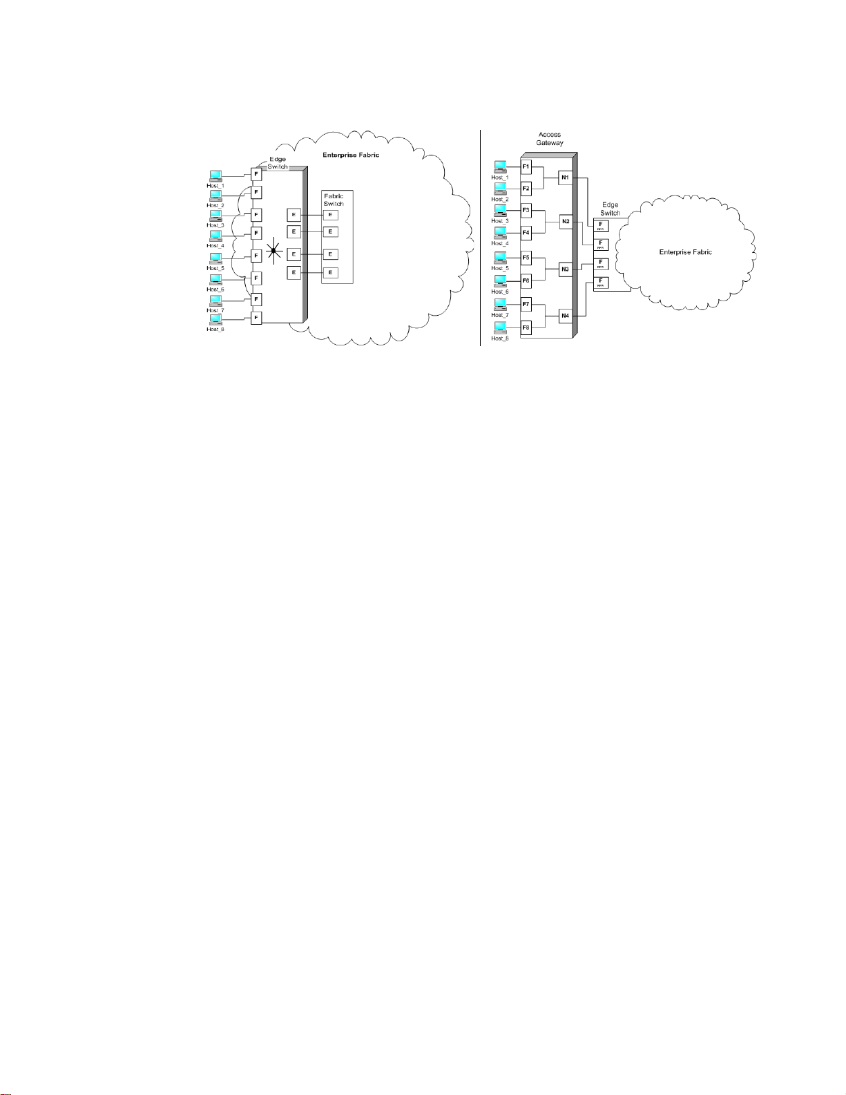
Figure 1 compares a configuration that connects eight hosts to the fabric using Brocade Access
Gateway to the same configuration with standard fabric switches.
Access Gateway Administrator’s Guide 1
53-1000605-01
Page 12
Overview of Brocade Access Gateway
1
FIGURE 1 Access Gateway and fabric switch comparison
The differences between the fabric switch (Fabric OS native mode) and Brocade Access Gateway
are as follows:
• The Fabric OS switch is a part of the fabric; it requires two to four times as many physical ports,
consumes fabric resources, and can connect to a Brocade-based fabric only.
• Brocade Access Gateway is outside the fabric; it reduces the number of switches in the fabric
and the number of required physical ports. You can connect Brocade Access Gateway to either
a Brocade, Brocade EOS, or Cisco-based fabric.
Brocade features in Access Gateway mode
When using a Brocade switch in Access Gateway mode, most features are no longer applicable.
These features include Admin Domains, Advanced Performance Monitoring, direct connection to
SAN target devices, Fibre Channel Arbitrated Loop support, Fabric Manager, FICON, IP over FC, ISL
trunking, extended fabrics, management platform services, name services (SNS), port mirroring,
SMI-S, and zoning. These switch features are available in the default switch mode of operation.
Access Gateway does not support any Secure Fabric OS features. All the security enforcement is
done in the enterprise fabric. The DCC policy in the enterprise fabric should include the N_Port
WWN and the port WWNs of all the HBAs connected to the F_Ports on Access Gateway that are
mapped to that N_Port. In case of a DCC policy violation, the port in the enterprise fabric to which
the F_Ports are connected and the N_Port is mapped to it on Access Gateway are disabled.
2 Access Gateway Administrator’s Guide
53-1000605-01
Page 13
Access Gateway port types
N_Port
F_Port
N_Port
F_Port
N_Port
F_Port
Hosts
Switch in AG mode
Edge Switch
Fabric
enabled
NPIV
N_Port
F_Port
E_Port
E_Port
N_Port
F_Port
Hosts
Switch in standard
Fabric Switch
E_Port
E_Port
Fabric
Access Gateway Ports
Fabric Switch Ports
default mode
Brocade Access Gateway differs from a typical fabric switch because it connects to the fabric using
node ports (N_Ports). Typically fabric switches connect to the enterprise fabric using ISL
(InterSwitch Link) ports, such as an E_Port.
The following defines the Fibre Channel (FC) port terms used in this manual:
• F_Port, fabric port. A switch port that connects a host, HBA, or storage device to the SAN.
• N_Port, node port. A host, HBA, or storage device port that connects to the F_Port of the
fabric switch.
Comparing FC port configurations
Brocade Access Gateway multiplexes host connections to the fabric. It presents an F_Port to the
host and an N_Port to an edge fabric switch. Using N_Port ID virtualization (NPIV), Brocade Access
Gateway allows multiple FC initiators to access the SAN on the same physical port. This reduces
the hardware requirements and management overhead of hosts to the SAN connections.
A fabric switch presents F_Ports (or FL_Ports) to the host and storage devices and presents
E_Ports, TE_Ports, or EX_Ports to other switches in the fabric. A fabric switch consumes SAN
resources, such as domain IDs, and participates in fabric management and zoning distribution. A
fabric switch requires more physical ports than Brocade Access Gateway to connect the same
number of hosts.
Access Gateway port types
1
Figure 2 compares the types of ports used by the Access Gateway to those used by a typical fabric
switch.
FIGURE 2 Port usage comparison
Access Gateway Administrator’s Guide 3
53-1000605-01
Page 14

1
NOTE
Port mapping
The two devices in Figure 2 on page 3 are the same. One switch is in default standard mode and the
other switch is in AG mode.
Tab le 1 compares port configuration with Access Gateway to a typical fabric switch.
TABLE 1 Port Configurations
Port Type Access Gateway Fabric switch
1. The switch is logically transparent to the fabric, therefore it does not participate in the SAN as a fabric switch.
Port mapping
Brocade Access Gateway uses mapping—that is, pre-provisioned routes—to direct traffic from the
hosts to the fabric. When you first enable Access Gateway mode, the F_Ports are mapped to a set
of predefined N_Ports, see Appendix A, “Default Port Mapping”. After the initial setup, you can
manually change the mapping, if required.
F_Port Yes Connects hosts to Brocade Access
Gateway.
N_Port Yes Connects Access Gateway to a fabric
switch.
E_Port
NA ISL is not supported.
1
Yes Connects devices, such as hosts, HBAs,
and storage to the fabric.
NA N_Ports are not supported.
Yes Connects the switch to other switches to
form a fabric.
4 Access Gateway Administrator’s Guide
53-1000605-01
Page 15
Port mapping
N_2
F_A2
Hosts
Access Gateway
Edge Switch
Fabric
(Switch_A)
enabled
NPIV
F_4
F_3
F_2
F_1
N_1
F_A1
enabled
NPIV
N_3
F_B1
enabled
NPIV
Host_1
Host_2
Host_3
Host_4
F_5
Host_5
F_6
Host_6
F_7
Host_7
F_8
Host_8
Edge Switch
(Switch_B)
N_4
F_B2
enabled
NPIV
1
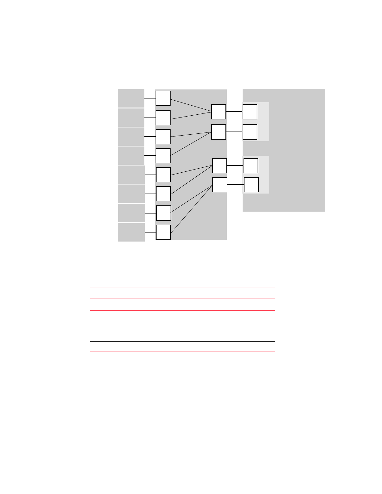
Figure 3 shows a mapping with eight F_Ports evenly mapped to four N_Ports on Brocade Access
Gateway. The N_Ports connect to the same fabric through different edge switches. This example is
also explains mapping, failover, and failback polices.
FIGURE 3 Example F_Port to N_Port mapping
Tab le 2 describes the mapping and fabric connection shown in Figure 3.
TABLE 2 Example port mapping
Access Gateway Fabric
F_Port N_Port Edge switch F_Port
F_1, F_2 N_1 Switch_A F_A1
F_3, F_4 N_2 Switch_A F_A2
F_5, F_6 N_3 Switch_B F_B1
F_7, F_8 N_4 Switch_B F_B2
Preferred Secondary N_Port mapping
F_Ports can be mapped to any of the N_Ports on an Access Gateway switch. Each F_Port can be
mapped to only one N_Port as its primary N_Port. When an F_Port is not mapped to any N_Port,
that port is disabled. Optionally, you can specify a Preferred Secondary N_Port for each F_Port. The
Preferred Secondary N_Port, if specified, is used when the primary mapped N_Port fails.
Access Gateway Administrator’s Guide 5
53-1000605-01
Page 16

Failover and Failback policies
NOTE
1
Failover and Failback policies
When a port is configured as an N_Port, the Failover policy is enabled by default. If a primary
N_Port goes offline because a cable is removed or any other offline event, the F_Ports that are
mapped to the N_Port are disabled. If a Preferred Secondary N_Port is set for any of the F_Ports,
and if those N_Ports are online, these F_Ports will be failed over to their respective Preferred
Secondary N_Port, and then re-enabled. Otherwise, if a Preferred Secondary N_Port is set, but is
not online, those F_Ports are disabled.
Alternatively, if a Preferred Secondary N_Port is not set for any of these F_Ports, these F_Ports
fail-over to other online N_Ports belonging to the same N_Port group, and then re-enables. The
FLOGI and FDISC requests are forwarded from F_Ports through the new N_Port. Failover of F_Ports
to new N_Ports generates a RASLOG message. If multiple N_Ports are available as candidates for
failover, Access Gateway selects one or more N_Ports so that the F_Ports are evenly balanced
across all these N_Ports.
Cold Failover
All F_Ports for an N_Port that goes offline are failed over to other N_Ports. However, if the N_Port
fails to come online after the switch comes online, it triggers cold failover of its F_Ports. If any of
these F_Ports have the Preferred Secondary N_Port set, and if the Preferred Secondary N_Port is
online, those F_Ports fail over to the Preferred Secondary N_Port during cold failover. If a Preferred
Secondary N_Port is set for any of these F_Ports and the Preferred N-Port is not online, then those
F_Ports are disabled. If the Preferred Secondary N_Port is not set for any of these F_Ports, these
F_Ports failover to any N_Ports on the switch so that the F_Ports are evenly balanced across all the
N_Ports belonging to the same N_Port group.
Access Gateway incorporates a number of Path Failover and Failback policies to ensure maximum
up time for the servers.
Port initialization
To ensure that all hosts are brought online when Brocade Access Gateway starts up, the ports are
initialized in the following manner:
1. All N_Ports are initialized. During N_Port initialization all the F_Ports are disabled (kept offline).
The ports are enabled or disabled as follows:
• Enabled (online) if the port receives a fabric login event and is connected to an F_Port of
• Disabled (offline) if the port is not connected to a fabric or is connected to a fabric port
2. All F_Ports mapped to online N_Ports are enabled.
3. F_Ports mapped to an offline N_Port with the failover policy enabled fail over to an online
N_Port.
4. The host logs in to the fabric as follows:
an edge switch that supports NPIV (N_Port ID virtualization).
that does not support NPIV.
6 Access Gateway Administrator’s Guide
53-1000605-01
Page 17
Access Gateway policies
a
b
c
d
e
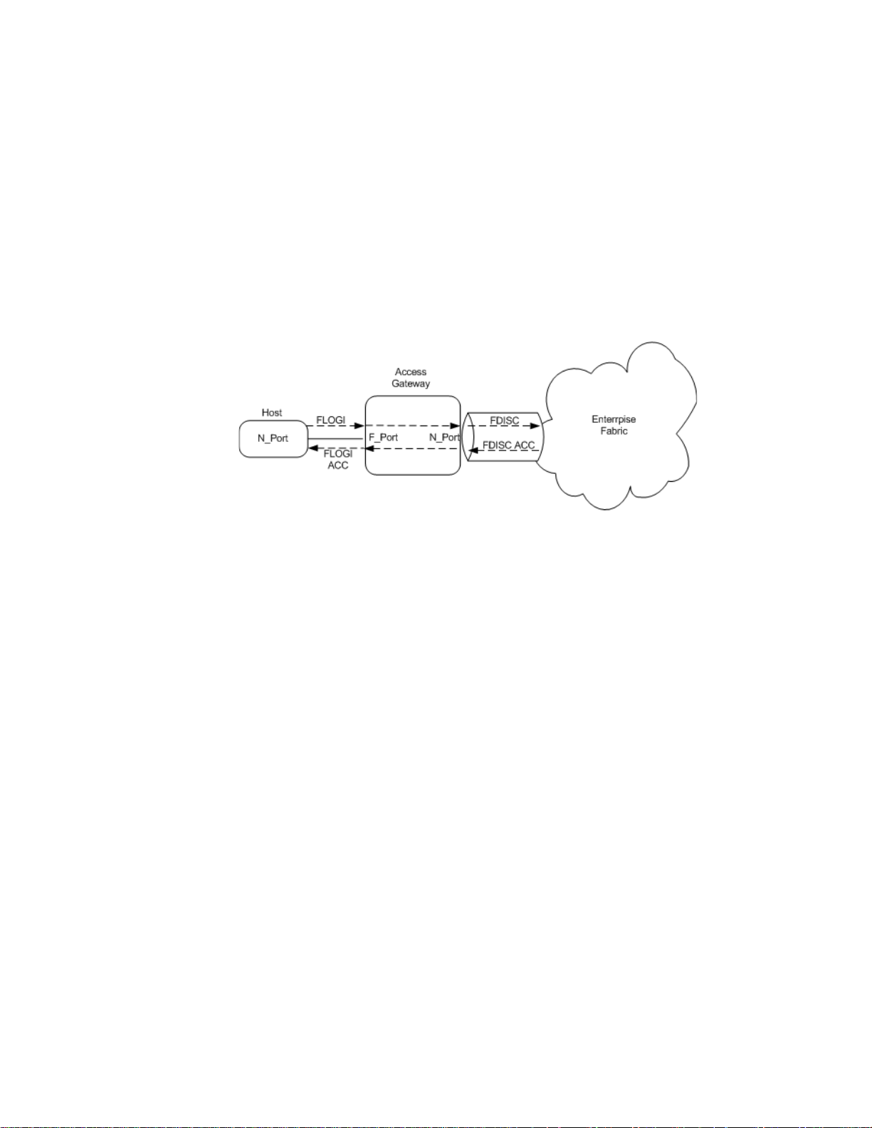
a. The host sends a FLOGI (fabric login) request.
b. Access Gateway converts the FLOGI request into an FDISC request to the fabric with the
same parameters as the host.
c. The fabric processes the request and sends an FDISC response.
d. Access Gateway converts the FDISC ACC response to the host as an FLOGI ACC using the
same parameters as the fabric.
e. The host receives the response from the fabric.
After ports are initialized, Access Gateway becomes logically transparent to the host and
the fabric, as shown in Figure 4.
1
FIGURE 4 Host log in request
Access Gateway policies
Access Gateway has four policies available to help you configure and maintain your Access
Gateway environment. The policies listed below are detailed later in this section.
• Path Failover policy enables hosts to automatically remap to an online N_Port within a port
group if the N_Port they are connected to goes offline.
• Failback policy automatically reroutes the F_Ports back to the originally mapped N_Ports if
within a port group as those N_Ports come back online.
• Port Grouping (PG) policy allows you to restrict Failover and Failback to a set of related
N_Ports.
• Automatic Port Configuration (APC) policy enables the switch to automatically detect ports
coming online and enforces a balance ratio of F_Ports to N_Ports.
Path Failover policy
The Brocade Access Gateway Path Failover policy allows hosts to automatically remap to an online
N_Port if the primary N_Port goes offline. The Path Failover policy evenly distributes the F_Ports
that are mapped to an offline N_Port among all the online N_Ports. The Path Failover policy is a
parameter of each N_Port. By default, the Path Failover policy is enabled for all N_Ports.
The following sequence describes how a failover event occurs:
1. An N_Port goes offline.
Access Gateway Administrator’s Guide 7
53-1000605-01
2. All F_Ports mapped to that N_Port are disabled.
Page 18

Access Gateway policies
NOTE
1
3. If the N_Port Failover policy is enabled, and a Preferred Secondary N_Port is specified for the
F_Port and that N_Port is online, the F-Port fails over to respective Preferred Secondary
N_Port, and then re-enables.
The Preferred Secondary N_Port is defined per F_Port. For example, if two F_Ports are mapped
to a primary N_Port1, you can define a secondary N_Port for one of those F_Ports and not
define a secondary N_Port for the other F_Port. This is done from a perspective of a server
admin. You must determine whether you want to define a preferred secondary map for each of
the servers or just a subset of the servers.
However, if the Preferred Secondary N_Port is not online, those F_Ports are disabled.
If the Preferred Secondary N_Port is NOT set for any of the F_Ports, these F_Ports will fail-over
to other available N_Ports belonging to the same N_Port Group, and then re-enables.
4. The host establishes a new connection with the fabric.
The Path Failover policy is enabled (or enforced) during power up.
Example: Path Failover Policy
This example shows the failover behavior in a scenario where two fabric ports go offline, one after
the other. Note that in this example we assume that no Pref erred Secondary N_P ort are set fo r
any of the F_Ports.
• First the edge switch F_A1 port goes offline, as shown in Figure 5 on page 9 Example 1 (left),
causing the corresponding Access Gateway N_1 port to be disabled.
The ports mapped to N_1 fail over; F_1 fails over to N_2 and F_2 fails over to N_3.
• Next the F_A2 port goes offline, as shown in Figure 5 on page 9 Example 2 (right), causing the
corresponding Access Gateway N_2 port to be disabled.
The ports mapped to N_2 (F_1, F_3, and F_4) fail over to N_3 and N_4. Note that the F_Ports
are evenly distributed to the remaining online N_Ports and that the F_2 did not participate in
the failover event.
8 Access Gateway Administrator’s Guide
53-1000605-01
Page 19

Access Gateway policies
NOTE
F_A2
Hosts
Access Gateway
Edge Switch
Fabric
(Switch_A)
enabled
NPIV
F_4
F_3
F_2
F_1
N_1
F_A1
enabled
NPIV
N_3
F_B1
enabled
NPIV
Host_1
Host_2
Host_3
Host_4
F_5
Host_5
F_6
Host_6
F_7
Host_7
F_8
Host_8
Edge Switch
(Switch_B)
N_4
F_B2
enabled
NPIV
N_2
Legend
Physical connection
Mapped online
Failover route online
Original mapped route
(offline)
Example 1
F_A2
Hosts
Access Gateway
Edge Switch
Fabric
(Switch_A)
enabled
NPIV
F_4
F_3
F_2
F_1
N_1
F_A1
enabled
NPIV
N_3
F_B1
enabled
NPIV
Host_1
Host_2
Host_3
Host_4
F_5
Host_5
F_6
Host_6
F_7
Host_7
F_8
Host_8
Edge Switch
(Switch_B)
N_4
F_B2
enabled
NPIV
Example 2
N_2
1
FIGURE 5 Example 1 and 2 Path Failover policy behavior
Failback policy
The Brocade Access Gateway Failback policy automatically reroutes the F_Ports back to the
primary mapped N_Ports as those N_Ports come back online, if failback is enabled for the N_Port.
Only the originally mapped F_Ports fail back. In the case of multiple N_Port failures, only F_Ports
that were mapped to the recovered N_Port experience failback. The remaining F_Ports are not
redistributed among the online N_Ports during the failback; this applies only if the APC is not set.
The Failback policy is an N_Port parameter. The Failback policy is enabled by default.
The following sequence describes how a failback event occurs:
1. When an N_Port comes back online, with failBack enabled, the F_Ports that were originally
mapped to it are disabled.
2. The F_Port is reenabled on the primary mapped N_Port.
3. The host establishes a new connection with the fabric.
Example: Failback Policy
In Example 3, the Brocade Access Gateway N_1 remains disabled because the corresponding
F_A1 port is offline. However, N_2 comes back online. See Figure 5 on page 9 for the original
failover scenario.
Access Gateway Administrator’s Guide 9
53-1000605-01
Page 20

Access Gateway policies
F_A2
Hosts
Access Gateway
Edge Switch
Fabric
(Switch_A)
enabled
NPIV
F_4
F_3
F_2
F_1
N_1
F_A1
enabled
NPIV
N_3
F_B1
enabled
NPIV
Host_1
Host_2
Host_3
Host_4
F_5
Host_5
F_6
Host_6
F_7
Host_7
F_8
Host_8
Edge Switch
(Switch_B)
N_4
F_B2
enabled
NPIV
N_2
Legend
Physical connection
Mapped online
Failover route online
Original mapped route
(offline)
Example 3
1
In Example 3, the ports F_1 and F_2 are mapped to N_1 and continue routing to N_3. Ports F_3
and F_4 were originally mapped to N_2 are disabled and rerouted to N_2, and then enabled.
FIGURE 6 Failback policy behavior
Port Grouping policy
When connecting an AG to multiple fabrics or isolating a subset of servers from other servers, you
might want to group a number of servers and their corresponding fabric ports. You can do this
using the N_Port grouping feature. Port groups cannot be overlapped. This means that an F_Port or
N_Port cannot belong to two different groups.
The Path Failover and Failback policies remain the same within each port group and the Preferred
Secondary N_Port can only specify the N_Ports from the same group. This is why it is
recommended to form groups before defining the preferred secondary path. In FOS v6.0.0 by
default, the Port group policy is enabled. When upgrading to FOS v6.0.0, all the ports on the switch
module belong to a default port group zero identified as pg0. If needed, additional port groups can
be defined.
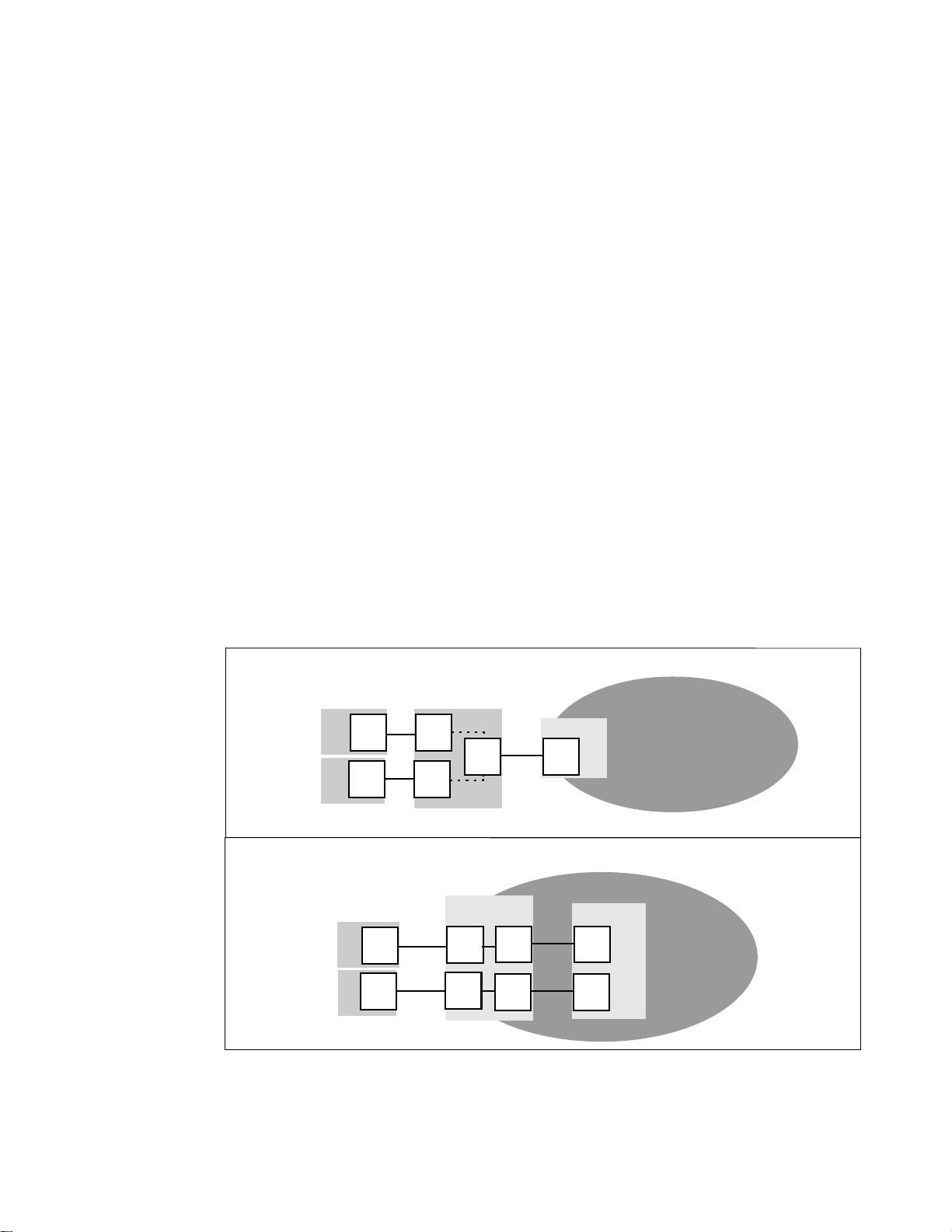
For example, Figure 7 on page 11 shows an example of pg0. If N_Port1 and 2 are in pg0 and
F_Ports 1-2 are using N_Port1 and N_Port1 goes offline, then F_Ports1-2 are routed through
N_Port2 because N_Port2 is in the same port group, pg0.
10 Access Gateway Administrator’s Guide
53-1000605-01
Page 21

Access Gateway policies
1
FIGURE 7 pg0 default setup
Figure 8 demonstrates that if you created port groups then, when an N_Port goes offline, the
F_Ports being routed through that port fails over to any of the N_Ports that are part of that port
group and are currently active. For example, if N_Port4 goes offline then F_Ports7 and 8 is routed
through to N_Port 3 as long as N_Port 3 is online because both N_Ports3 and 4 belong to the same
port group PG2. If no active N_Ports are available the F_Ports will be disabled. The F_Ports
belonging to a port group will not failover to N_Ports belonging to another port group.
FIGURE 8 Port grouping behavior
In Fabric OS 6.0.0, the PG policy is enabled by default. All N_Ports will be part of a default port
group with a special identifier 0. This port group is known as pg0.
When a dual redundant fabric configuration is used, F_Ports connected to an Access
Gateway-enabled switch can access some target devices from both the fabrics. In these cases, it is
recommended to have paths fail over to the redundant fabric when the primary fabric goes down.
This can be achieved by grouping N_Ports connected to the redundant fabrics into one single port
group.
Access Gateway Administrator’s Guide 11
53-1000605-01
Page 22

Access Gateway policies
ATTENTION
NOTE
NOTE
ATTENTION
1
If N_Ports connected to unrelated fabrics are grouped together, N_Port failover within a port group
can cause the F_Ports to connect to a different fabric and the F_Port may lose connectivity to the
targets it was connected to before failover, causing I/O disruption.
You can create new port groups and add N_Ports to these groups. However, all N_Ports which are
not part of any user-created port group will be part of the default port group pg0.
Creation of overlapping port groups is not allowed. So if you have an N_Port that is specified as a
Preferred Secondary N_Port and belongs to another port group, it cannot be part of any other port
group. Port Group creation would fail in this case.
If this policy is disabled while the Access Gateway switch is online, all the user-defined port groups
will be deleted, but F_Port to N_Port mappings will remain unchanged.
While Port Grouping policy is set, Preferred Secondary N_Ports can be set only in accordance with
existing Port Groups. While Port Grouping policy is in force, setting an N_Port as Preferred for
F_Ports will fail if any of the specified F_Ports are mapped to another N_Port outside the Port
Group.
Firmware upgrade and downgrade
If you upgrade the firmware from v5.3.x to v6.0.0, then the PG policy is enabled with the default
port group pg0 containing all the N_Ports. A firmware downgrade from v6.0.0 to v5.3.x is not
allowed if the PG policy is enabled. You must disable the PG policy before downgrading the
firmware.
During a downgrade to v5.3.x, all preferred settings are lost.
Automatic port configuration (APC)
APC is an optional policy and is disabled by default. When APC is enabled, the Access
Gateway-enabled switch automatically discovers the port type. For example, if a switch is
connected to a port on Access Gateway, then Access Gateway determines that it is connected to a
switch and configures the port as an N_Port. If a host is connected to a port on Access Gateway,
then Access Gateway determines that it is connected and configures the port as an F_Port.
After all the port types are determined, dynamic mapping between F_Ports and N_Ports is created
and evenly distributes F_Ports across all N_Ports. While the APC is enabled, you cannot manually
configure F_Ports to N_Port mapping.
When this policy is enabled, existing F_Port to N_Port mappings are deleted. This process is
disruptive to F_Ports and N_Ports. It is recommended that the switch is disabled when this policy is
enabled. Therefore, it is recommended to perform a configupload before enabling this feature.
When this policy is disabled, N_Port configuration and F_Port to N_Port mapping revert back to the
default factory configuration for that platform.
12 Access Gateway Administrator’s Guide
53-1000605-01
Page 23

Access Gateway policies
NOTE
The APC is mutually exclusive with the Port Grouping policy. When this policy is enabled on a switch
connected to multiple fabrics, no attempt is made by Access Gateway to restrict failover behavior
even if N_Ports are connected to unrelated fabrics. It is recommended not to use this policy when
Access Gateway is connected to multiple fabrics.
If you need to restore the mapping that was in place before the APC was enabled, then you must
perform the following while enabling and disabling APC:
1. While enabling APC
a. Upload the config file
b. Disable the switch
c. Enable APC
d. Enable the switch
2. While disabling APC
a. Disable the switch
b. Disable APC
c. Enable the switch
1
d. Download the config file stored before enabling APC
For full instructions on how to enable the APC, refer to Chapter 4, “Managing Ports in Access
Gateway mode”.
Rebalancing of F_Ports
When the APC is enabled there will be no static mappings between F_Ports and N_Ports and no
F_Ports will be tied to a specific N_Port. When an F_Port comes online after the initial mapping is
done, the F_Ports are automatically routed through one of the available N_Ports such that the
F_Ports are evenly balanced across all the available N_Ports. Similarly if a new N_Port comes
online after initial F_Port initialization is done, some of the F_Ports being routed through existing
N_Ports would be failed-over to the new N_Ports, if rebalancing is needed.
Due to the disruption caused by the redistribution of F_Ports, it is recommended to map all N_Ports
on the module during a maintenance window.
Firmware upgrade and downgrade
If you upgrade from Fabric OS v5.3.x to v6.0.0, then by default the APC is disabled. A firmware
downgrade from v6.0.0 to v5.3.x is not allowed if the APC is enabled. The policy must be disabled
before downgrading the firmware.
Access Gateway Administrator’s Guide 13
53-1000605-01
Page 24

Access Gateway policies
1
14 Access Gateway Administrator’s Guide
53-1000605-01
Page 25

Chapter
NOTE
NOTE
Configuring Access Gateway
This chapter describes the initial setup required to deploy Brocade Access Gateway.
Refer to the Web Tools Administrator’s Guide to manage Access Gateway using Web Tools.
In this chapter
•Verifying the fabric and edge switch settings . . . . . . . . . . . . . . . . . . . . . . . . 15
•Enabling Access Gateway mode. . . . . . . . . . . . . . . . . . . . . . . . . . . . . . . . . . . 16
Verifying the fabric and edge switch settings
To connect hosts to the fabric using Access Gateway, configure the fabric using the following
parameters. The listed parameters apply to Brocade-, Brocade EOS-, and Cisco-based fabrics:
2
• Install and configure the switch as described in the switch’s Hardware Reference Manual
before performing these procedures.
• Verify that the interop mode parameter is set to ‘0’, Brocade Native mode, or the switch mode
is in ‘Native’ mode.
• Configure the F_Ports on the edge switch to which Access Gateway is connected as follows:
• Enable NPIV.
• Disable long distance mode.
• Allow multiple logins. The recommended fabric login setting is set to the maximum allowed
per port and per switch.
• Use only WWN zoning throughout the fabric. Access Gateway does not support domain ID and
other types of zoning schemes.
• Include either Access Gateway WWN or the port WWN of the N_Ports and HBA WWNs that will
be connected to AG F_Ports to the ACL list in ACL policies.
• Allow inband queries for forwarded fabric management requests from the hosts. Add the
Access Gateway switch WWN to the access list if inband queries are restricted.
Before connecting Access Gateway to a Brocade-based fabric, disable Fabric OS Management
Server Platform Service.
Access Gateway Administrator’s Guide 15
53-1000605-01
Page 26

Enabling Access Gateway mode
NOTE
ATTENTION
2
Enabling Access Gateway mode
This section explains how to change the switch mode from Fabric OS Native mode to Access
Gateway mode using the command line interface. Converting a switch to a Brocade Access
Gateway allows you to use the switch as a device management tool that transparently connects
hosts to the fabric.
On the 200E, you must enable all ports using POD licensing before enabling Access Gateway mode.
Using the CLI to enable Access Gateway mode
Enabling Access Gateway mode is a disruptive process; the switch is disabled and rebooted. After
you enable Access Gateway mode, only a limited subset of Fabric OS commands are available and
all fabric-related service requests are forwarded to the fabric switches. For more information on the
available Access Gateway commands, refer to Appendix D, “Access Gateway Commands”.
You must verify that the interop mode is set to ‘0’, Brocade Native mode, by viewing the switchshow
command output. If the switch mode setting is anything other than ‘Native’ you must change the
interop mode to ‘0’ before continuing with enabling Access Gateway mode.
When you enable Access Gateway mode some fabric information is erased, such as the zone and
security databases. To recover the information, save the switch configuration before enabling
Access Gateway mode.
Tab le 3 describes the commands used to enable Access Gateway mode.
TABLE 3 Access Gateway Enable Command list
Command Description
switchDisable Disable the switch.
configUpload Save the switch’s current configuration.
When you enable Access Gateway mode some fabric information is
erased, such as the zone and security databases.
--modeenable Enable Access Gateway mode.
ag
The switch will reboot and come back online in Access Gateway mode.
--modeshow Verify that Access Gateway mode has been enabled.
ag
--mapshow Display the F_Por t to N_Port mapping.
ag
switchShow Ensure that all the ports are mapped and online.
To enable Access Gateway mode from the CLI
You must perform the switchShow command first to see which mode the switch is in. If the switch
is not in Native mode, then you must disable the switch and set the switch to Native mode. See “To
change the switch mode” on page 17.
1. Log in to the switch as admin.
2. Enter the switchShow command to display the current switch configuration.
The following example shows a switch in the Fabric OS Native mode where switchMode
displays as Native.
16 Access Gateway Administrator’s Guide
53-1000605-01
Page 27

Enabling Access Gateway mode
switch:admin> switchshow
switchName: switch
switchType: 43.2
switchState: Online
switchMode: Native
switchRole: Principal
switchDomain: 1
switchId: fffc01
switchWwn: 10:00:00:05:1e:03:4b:e7
zoning: OFF
switchBeacon: OFF
Area Port Media Speed State Proto
=====================================
0 0 -- N4 No_Module
1 1 cu N4 Online F-Port 50:06:0b:00:00:3c:b7:32
2 2 cu N4 Online F-Port 10:00:00:00:c9:35:43:f5
3 3 cu AN No_Sync
4 4 cu AN No_Sync Disabled (Persistent)
5 5 cu N4 Online F-Port 50:06:0b:00:00:3c:b4:3e
6 6 cu N4 Online F-Port 10:00:00:00:c9:35:43:f3
7 7 cu AN No_Sync Disabled (Persistent)
8 8 cu AN No_Sync
9 9 cu AN No_Sync Disabled (Persistent)
10 10 cu AN No_Sync Disabled (Persistent)
11 11 cu AN No_Sync Disabled (Persistent)
12 12 cu AN No_Sync Disabled (Persistent)
13 13 cu AN No_Sync Disabled (Persistent)
14 14 cu AN No_Sync Disabled (Persistent)
15 15 cu AN No_Sync Disabled (Persistent)
16 16 cu AN No_Sync Disabled (Persistent)
17 17 -- N4 No_Module
18 18 -- N4 No_Module
19 19 -- N4 No_Module
20 20 -- N4 No_Module
21 21 id N4 Online E-Port segmented,(zone conflict)(Trunk
master)
22 22 id N4 Online E-Port (Trunk port, master is Port 21 )
23 23 id N4 Online E-Port (Trunk port, master is Port 21 )
2
See Tab le 4 on page 18 for a description of the port state.
If the switch mode displays anything other than Native, you must change the interop mode
parameter to ‘0’.
To change the switch mode
1. Enter the switchDisable command to disable the switch.
switch:admin> switchdisable
2. Save the switch configuration using the configUpload command.
a. Verify that the FTP service is running on the host computer.
b. Enter the configUpload command.
The command becomes interactive and you are prompted for the required information.
3. Enter the configure command and verify that interop mode parameter is set to ‘0’.
Access Gateway Administrator’s Guide 17
53-1000605-01
Page 28

Enabling Access Gateway mode
2
If the parameter is set to ‘0’, continue to the next step. If the parameter is not set to ‘0’,
change the parameter and reboot the switch.
4. Enter the ag
switch:admin> ag --modeenable
--modeenable command to enable Access Gateway mode.
The switch automatically reboots and comes back online in Access Gateway mode using a
factory default F_Port to N_Port mapping. For more information on which ports are mapped by
default, refer to Appendix A, “Default Port Mapping”.
5. Enter the ag
switch:admin> ag --modeshow
Access Gateway mode is enabled.
--modeshow command to verify that Access Gateway mode is enabled.
6. Enter the ag --mapshow command without any options to display all the mapped ports.
The following example shows a reconfigured mapping; three N_Ports: 17, 19 and 20 have no
mappings and are not connected to the fabric.
TABLE 4 Port State Description
State Description
No _Card No interface card present
No _Module No module (GBIC or other) present
Mod_Val Module validation in process
Mod_Inv Invalid module
No_Light The module is not receiving light
No_Sync Receiving light but out of sync
In_Sync Receiving light and in sync
Laser_Flt Module is signaling a laser fault
Port_Flt Port marked faulty
Diag_Flt Port failed diagnostics
Lock_Ref locking to the reference signal
Testing running diagnostics
Offline Connection not established (only for
virtual ports)
Online The port is up and running
switch:admin> ag --mapshow
N_Port Configured_F_Ports Current_F_Ports Failover Failback PG_ID PG_Name
---------------------------------------------------------------------------------- 0 9;10 None 1 1 N/A N/A
17 None None 1 1 N/A N/A
18 3;4 None 1 1 N/A N/A
19 None None 1 1 N/A N/A
20 None None 1 1 N/A N/A
21 1;2;11;12 1;2 1 1 N/A N/A
22 5;13;14 5 1 1 N/A N/A
23 6;15;16 6 1 1 N/A N/A
18 Access Gateway Administrator’s Guide
53-1000605-01
Page 29

Enabling Access Gateway mode
7. E nt e r t he switchShow command without any options to display the status of all ports.
switch:admin> switchshow
switchName: switch
switchType: 43.2
switchState: Online
switchMode: Access Gateway Mode
switchWwn: 10:00:00:05:1e:03:4b:e7
switchBeacon: OFF
Area Port Media Speed State Proto
=====================================
0 0 -- N4 No_Module
1 1 cu N4 Online F-Port 50:06:0b:00:00:3c:b7:32 0x5a0101
2 2 cu N4 Online F-Port 10:00:00:00:c9:35:43:f5 0x5a0003
3 3 cu N4 Online F-Port 50:06:0b:00:00:3c:b6:1e 0x5a0102
4 4 cu N4 Online F-Port 10:00:00:00:c9:35:43:9b 0x5a0002
5 5 cu N4 Online F-Port 50:06:0b:00:00:3c:b4:3e 0x5a0201
6 6 cu N4 Online F-Port 10:00:00:00:c9:35:43:f3 0x5a0202
7 7 cu AN No_Sync Disabled (Persistent)
8 8 cu N4 Online F-Port 10:00:00:00:c9:35:43:a1 0x5a0001
9 9 cu AN No_Sync Disabled (Persistent)
10 10 cu AN No_Sync Disabled (Persistent)
11 11 cu AN No_Sync Disabled (Persistent)
12 12 cu AN No_Sync Disabled (Persistent)
13 13 cu AN No_Sync Disabled (Persistent)
14 14 cu AN No_Sync Disabled (Persistent)
15 15 cu AN No_Sync Disabled (Persistent)
16 16 cu AN No_Sync Disabled (Persistent)
17 17 -- N4 No_Module
18 18 -- N4 No_Module
19 19 id N4 No_Light
20 20 -- N4 No_Module
21 21 id N4 Online N-Port 10:00:00:05:1e:35:10:1e 0x5a0200
22 22 id N4 Online N-Port 10:00:00:05:1e:35:10:1e 0x5a0100
23 23 id N4 Online N-Port 10:00:00:05:1e:35:10:1e 0x5a0000
2
Access Gateway Administrator’s Guide 19
53-1000605-01
Page 30

Enabling Access Gateway mode
2
20 Access Gateway Administrator’s Guide
53-1000605-01
Page 31

Chapter
Disabling Access Gateway Mode
This chapter describes how to disable Access Gateway mode. Disabling Access Gateway mode is
disruptive; the switch is disabled and rebooted.
In this chapter
•Before you begin . . . . . . . . . . . . . . . . . . . . . . . . . . . . . . . . . . . . . . . . . . . . . . . 21
•Disabling Access Gateway mode . . . . . . . . . . . . . . . . . . . . . . . . . . . . . . . . . . 21
•Notes on joining the switch to a fabric. . . . . . . . . . . . . . . . . . . . . . . . . . . . . . 22
Before you begin
Always back up the current configuration before enabling or disabling Access Gateway mode.
Enabling Access Gateway mode clears the security and zone databases. Disabling Access Gateway
mode clears the F_Port to N_Port mapping.
3
Backing up the Switch Configuration
Save the configuration before setting up the switch in Access Gateway mode. If you want more
information on backing up and restoring the configuration file, refer to the Fabric OS
Administrator’s Guide.
To upload a configuration file using CLI
1. Verify that the FTP service is running on the host computer.
2. Connect to the switch and log in as admin.
3. Enter the configUpload command. The command becomes interactive and you are prompted
for the required information.
Disabling Access Gateway mode
Access Gateway mode transforms the switch into a device management tool. After Access Gateway
mode is disabled, the switch starts in Fabric OS Native mode, and the standard set of Fabric OS
commands is available. Disable Access Gateway mode using the command line interface. The
switch will segment from the fabric upon reboot, to join the switch to the core fabric, refer to “Notes
on joining the switch to a fabric” on page 22.
Access Gateway Administrator’s Guide 21
53-1000605-01
Page 32

Notes on joining the switch to a fabric
NOTE
NOTE
NOTE
3
Using the CLI to disable Access Gateway mode
After you disable Access Gateway mode, use the instructions in the Fabric OS Administrator’s
Guide to reconfigure the switch and join it to the fabric.
Disabling Access Gateway mode clears the current Access Gateway mode configuration and reboots
the switch.
To disable Access Gateway mode
1. Connect and log in to the switch.
2. Enter the ag
switch:admin> ag --modeshow
Access Gateway mode is enabled
3. Enter the switchDisable command to disable the switch.
switch:admin> switchdisable
To save the Access Gateway configuration, use the configUpload command before proceeding
with the next step.
4. Enter the ag command with the
switch:admin> ag --modedisable
The switch automatically reboots and comes back online using the fabric switch configuration;
the Access Gateway parameters, such as F_Port to N_Port mapping, failover, and failback
policies are automatically removed.
5. Enter the ag
switch:admin> ag --modeshow
Access Gateway mode is NOT enabled
--modeshow command to verify that the switch is in Access Gateway mode.
--modedisable operand to disable Access Gateway mode.
--modeshow command to verify that Access Gateway mode is disabled.
Use the configDownload command to restore a previous fabric configuration.
Notes on joining the switch to a fabric
After the switch reboots when Access Gateway mode is disabled, the default zone is set to no
access. Therefore, the switch does not immediately join the fabric to which it is connected. Use one
of the following methods to join the switch to the fabric:
• If you saved a Fabric OS configuration before enabling AG mode, download the configuration
using the configDownload command. See “To use a previous configuration” on page 23.
• If you want to join the switch to the fabric using the fabric configuration, follow the steps in “To
allow the switch to merge with the fabric” on page 23.
22 Access Gateway Administrator’s Guide
53-1000605-01
Page 33

Notes on joining the switch to a fabric
NOTE
To use a previous configuration
1. Enter the switchDisable command to disable the switch.
2. Enter the configDownload command to revert to the previous configuration.
3. Enter the switchEnable command to bring the switch back online.
The switch automatically joins the fabric.
To allow the switch to merge with the fabric
Only connect the switch to the fabrics which you want it to join.
1. Enter the switchDisable command to disable the switch.
3
2. Enter the defZone
3. Enter the cfgSave command to commit the defzone changes.
4. Enter the switchEnable command to enable the switch and allow it to merge with the fabric.
The switch automatically joins the fabric.
--allAccess command to allow the switch to merge with the fabric.
Access Gateway Administrator’s Guide 23
53-1000605-01
Page 34

Notes on joining the switch to a fabric
3
24 Access Gateway Administrator’s Guide
53-1000605-01
Page 35

Chapter
NOTE
Managing Ports in Access Gateway mode
This chapter explains how to use the CLI to manage the ports on Brocade Access Gateway.
Refer to the Web Tools Administrator’s Guide for information on setting up Access Gateway using
Web Tools.
In this chapter
•Determining the mapping and port status . . . . . . . . . . . . . . . . . . . . . . . . . . 25
•Configuring port maps. . . . . . . . . . . . . . . . . . . . . . . . . . . . . . . . . . . . . . . . . . . 27
•Configuring additional F_Ports . . . . . . . . . . . . . . . . . . . . . . . . . . . . . . . . . . . . 30
•Managing policies . . . . . . . . . . . . . . . . . . . . . . . . . . . . . . . . . . . . . . . . . . . . . . 32
4
Determining the mapping and port status
This section explains how to display the current mapping and port status.
Displaying the port mapping
This section explains how to display the mapped routes of the host connections to the fabric on
Brocade Access Gateway. F_Ports are mapped to N_Ports.
See the Fabric OS Command Reference for more details on using the ag command with the
--mapshow operand.
To display all mappings
1. Connect and log in to the switch.
2. Enter the ag
--mapshow command.
Access Gateway Administrator’s Guide 25
53-1000605-01
Page 36

Determining the mapping and port status
4
The following information displays.
N_Port Port numbers of ports locked in N_Port mode.
Configured F_Ports List of F_Ports that are mapped to the corresponding N_Port.
For example, in the following sample output, F_Ports 9 and 10
are mapped to N_Port 0.
Current F_Ports Shows the F_Ports that are currently connected to the fabric on
the corresponding N_Port.
In the case of failover, the Current F_Ports and Configured
F_Ports differ. For example, in the following ag--mapshow
sample output, ports 9 and 10 are mapped to 0. However, 0 is
offline and therefore, 9 and 10 failed over to 22 and 23.
Failover and Failback Indicates whether the N_Port policy is enabled (1) or disabled
(0).
PG_ID and PG_Name Indicates whether the Port Grouping policy is enabled (1) or
disabled (0).
switch:admin> ag --mapshow
N_Port Configured_F_Ports Current_F_Ports Failover Failback PG_ID PG_Name
---------------------------------------------------------------------------------- 0 9;10 None 1 1 N/A N/A
17 None None 1 1 N/A N/A
18 3;4 None 1 1 N/A N/A
19 None None 1 1 N/A N/A
20 None None 1 1 N/A N/A
21 1;2;11;12 1;2 1 1 N/A N/A
22 5;13;14 5;9 1 1 N/A N/A
23 6;15;16 6;10 1 1 N/A N/A
-----------------------------------------------------------------------------------
To display an N_Port map
1. Connect and log in to the switch.
2. Enter the ag
--mapshow command and specify the port number to display the values of the
the N_Port flivver and failback policies and the mapped F_Ports.
switch:admin> ag --mapshow 0
N_Port : 0
Failover(1=enabled/0=disabled) : 1
Failback(1=enabled/0=disabled) : 1
Current F_Ports : 2;8
Configured F_Ports : 2
PG_ID : 0
PG_Name : pg0
26 Access Gateway Administrator’s Guide
53-1000605-01
Page 37

Configuring port maps
NOTE
Displaying the port status
This section explains how to determine the port status.
To display the port status
1. Connect and log in to the switch.
2. Enter the switchShow command without any options to display the status of all ports.
switch:admin> switchshow
switchName: switch
switchType: 43.2
switchState: Online
switchMode: Access Gateway Mode
switchWwn: 10:00:00:05:1e:03:4b:e7
switchBeacon: OFF
Area Port Media Speed State Proto
=====================================
0 0 -- N4 No_Module
1 1 cu N4 Online F-Port 50:06:0b:00:00:3c:b7:32 0x5a0101
2 2 cu N4 Online F-Port 10:00:00:00:c9:35:43:f5 0x5a0003
3 3 cu N4 Online F-Port 50:06:0b:00:00:3c:b6:1e 0x5a0102
4 4 cu N4 Online F-Port 10:00:00:00:c9:35:43:9b 0x5a0002
5 5 cu N4 Online F-Port 50:06:0b:00:00:3c:b4:3e 0x5a0201
6 6 cu N4 Online F-Port 10:00:00:00:c9:35:43:f3 0x5a0202
7 7 cu AN No_Sync Disabled (Persistent)
8 8 cu N4 Online F-Port 10:00:00:00:c9:35:43:a1 0x5a0001
9 9 cu AN No_Sync Disabled (Persistent)
10 10 cu AN No_Sync Disabled (Persistent)
11 11 cu AN No_Sync Disabled (Persistent)
12 12 cu AN No_Sync Disabled (Persistent)
13 13 cu AN No_Sync Disabled (Persistent)
14 14 cu AN No_Sync Disabled (Persistent)
15 15 cu AN No_Sync Disabled (Persistent)
16 16 cu AN No_Sync Disabled (Persistent)
17 17 -- N4 No_Module
18 18 -- N4 No_Module
19 19 id N4 No_Light
20 20 -- N4 No_Module
21 21 id N4 Online N-Port 10:00:00:05:1e:35:10:1e 0x5a0200
22 22 id N4 Online N-Port 10:00:00:05:1e:35:10:1e 0x5a0100
23 23 id N4 Online N-Port 10:00:00:05:1e:35:10:1e 0x5a0000
4
For a description of the port state, see Table 4 on page 18.
Configuring port maps
In Access Gateway mode, the F_Ports are mapped to Imports. The first time Access Gateway mode
is enabled, the default F_Port to N_Port mapping is used. For more information on which ports are
mapped by default, refer to Appendix A, “Default Port Mapping”.
This section explains how to change the mapping. When you update the mapping, only the F_Ports
that are added or removed are affected.
Access Gateway Administrator’s Guide 27
53-1000605-01
Page 38

Configuring port maps
NOTE
4
For bladed servers, the HBA connects to the internal ports. Therefore, the internal ports are F_Ports
and by default, only the external ports are configured as Imports.
Adding F_Ports
Adding an F_Port to an N_Port routes that traffic to and from the fabric through the specified
N_Port. When failover is enabled and the N_Port goes offline or fails, the F_Port automatically
routes to another N_Port that is connected to the same fabric.
An F_Port can be assigned to only one N_Port at a time. If the F_Port is assigned to another N_Port,
you must remove it from the N_Port before you can add it using the following procedure. To remove
an N_Port, refer to “To remove an F_Port from an N_Port” on page 29.
To add F_Ports to an N_Port
1. Connect and log in to the switch.
2. Enter the ag command with the
--mapdel <n_portnumber> <F_Port1;...;F_Port2> operand to
remove the F_Port from the N_Port. Where the f_portlist can contain multiple F_Port numbers
separated by semicolons, for example “17;18”.
switch:admin> ag --mapdel 10 6
F-Port to N-Port mapping has been updated successfully
3. Enter the switchshow command to verify that the F_Port is free (unassigned).
Unassigned F_Port status is Disabled (No mapping for F-Port). See port 6 in the following
example.
switch:admin> switchshow
switchName: fsw534_4016
switchType: 45.0
switchState: Online
switchMode: Access Gateway Mode
switchWwn: 10:00:00:05:1e:02:1d:b0
switchBeacon: OFF
Area Port Media Speed State Proto
=====================================
0 0 cu AN No_Sync
1 1 cu AN No_Sync Disabled (N-Port Offline for F-Port)
2 2 cu AN No_Sync Disabled (N-Port Offline for F-Port)
3 3 cu AN No_Sync Disabled (N-Port Offline for F-Port)
4 4 cu AN No_Sync Disabled (N-Port Offline for F-Port)
5 5 cu AN No_Sync Disabled (N-Port Offline for F-Port)
6 6 cu AN No_Sync Disabled (No mapping for F-Port)
7 7 cu AN No_Sync
8 8 cu AN No_Sync
9 9 cu AN No_Sync
10 10 -- N4 No_Module
11 11 -- N4 No_Module
12 12 -- N4 No_Module
13 13 id N4 Online N-Port 10:00:00:05:1e:35:10:1e 0x5a0a00
14 14 id N4 Online N-Port 10:00:00:05:1e:35:10:1e 0x5a0900
15 15 id N4 Online N-Port 10:00:00:05:1e:35:10:1e 0x5a0800
28 Access Gateway Administrator’s Guide
53-1000605-01
Page 39

Configuring port maps
4
4. Enter the ag command with the --mapadd <n_portnumber> “<f_port1;f_port2;...> operand to
add the list of F_Ports to the N_Port.
Where the f_portlist can contain multiple F_Port numbers separated by semicolons, for
example “17;18”.
switch:admin> ag --mapadd 13 "6;7"
F-Port to N-Port mapping has been updated successfully
5. Enter the ag --mapshow command with the n_portnumber operand to display a list of
mapped F_Ports. Verify that the F_Ports you added appear in the list.
switch:admin> ag --mapshow 13
N_Port : 13
Failover(1=enabled/0=disabled) : 1
Failback(1=enabled/0=disabled) : 1
Current F_Ports : None
Configured F_Ports : 6;7
PG_ID : 0
PG_Name : pg0
Removing F_Ports
Removing an F_Port from an N_Port unassigns the F_Port. The F_Port status changes to Disabled
(No mapping for F-Port).
To remove an F_Port from an N_Port
1. Connect and log in to the switch.
2. Enter the ag
--mapdel command with the <n_portnumber> <f_port1;f_port2;...> operands to
remove the list of F_Ports from the N_Port.
switch:admin> ag --mapdel 13 “5;6”
F-Port to N-Port mapping has been updated successfully
3. Enter the ag --mapshow command with the n_portnumber operand to display a list of
mapped F_Ports. Verify that the F_Ports you removed are not in the list.
switch:admin> ag --mapshow 13
N_Port : 13
Failover(1=enabled/0=disabled) : 1
Failback(1=enabled/0=disabled) : 1
Current F_Ports : None
Configured F_Ports : 7
PG_ID : 0
PG_Name : pg0
Specifying Preferred Secondary N_Ports
Specifying a Preferred Secondary N_Port adds a secondary N_Port for the specified F_Port to fail
over to. You must add the F_Ports to the N_Port with the prefset command to have an extra group
of F_Ports that can failover to the N_Port, if the default port mapping fails. For example:
--prefset "F_Port [;F_Port2;...]" N_Port
Access Gateway Administrator’s Guide 29
53-1000605-01
Page 40

Configuring additional F_Ports
NOTE
4
The prefset command sets the preferred N_Port for one or more F_Ports. Preferred mapping is
optional. Preferred F_Port to N_Port Mapping provides an alternate N_Port for F_Ports to come
online for predictable failover and failback. An F_Port must have primary N_Port mapping before a
secondary N_Port can be configured. The list of F_Ports to mapped must be enclosed in quotation
marks. Port numbers must be separated by a semicolon.
You delete these same F_Ports using the prefdel command, for example:
The prefdel command deletes the preferred N_Port for the specified F_Port(s). The list of F_Ports to
delete from the secondary mapping must be enclosed in quotation marks. Port numbers must be
separated by a semicolon.
To add a Preferred Secondary F_Ports 3 and 9 to N_Port 4
1. Connect and log in to the switch.
2. Enter the ag --prefset command with the <F_Port1;F_Port2; ...> <N_Port> operands to add
--prefdel "F_Port [;F_Port2;...]" N_Port
the Preferred Secondary F_Ports to the specified N_Port.
switch:admin> ag --prefset "3;9" 4
Preferred N_Port is set successfully for the F_Port[s]
To remove the Preferred Secondary F_Ports 3 and 9 from N_Port 4
1. Connect and log in to the switch.
2. Enter the ag --prefdel command with the <F_Port1;F_Port2; ...> <N_Port> operands to delete
the preferred F_Port mapping from the specified N_Port.
switch:admin> ag --prefdel "3;9" 4
Preferred N_Port is deleted successfully for the F_Port[s]
Configuring additional F_Ports
By default, on embedded switches, only the internal ports of Brocade Access Gateway are
configured as F_Ports. All external ports are configured (locked) as N_Ports. For more information
on which ports are mapped by default, refer to Appendix A, “Default Port Mapping”. The internal
ports connect hosts in the bladed server and external ports connect to the fabric.
To connect an additional FCP initiator to an external port and reconfigure an N_Port as an F_Port
1. Remap any F_Ports on the N_Port being converted. See “Adding F_Ports” on page 28.
2. Unlock the N_Port mode to change the port type to an F_Port. See “Unlocking N_Port mode”
on page 31.
3. Map the newly configured F_Port to an N_Port. See “Adding F_Ports” on page 28.
4. Connect the HBA, host, or other FCP initiator to the F_Port.
A switch in Access Gateway mode must have at least one port configured as an N_Port.
Therefore, the maximum number of F_Ports that can be mapped to an N_Port is the number of
ports on the switch minus one.
30 Access Gateway Administrator’s Guide
53-1000605-01
Page 41

Configuring additional F_Ports
Figure 9 shows a host connected to an embedded switch’s external F_Port when Brocade Access
Gateway is enabled. The newly configured F_Port was mapped to an N_Port.
4
FIGURE 9 Example of adding an external F_Port (F9) on an embedded switch
Unlocking N_Port mode
By default, on embedded switches, all external ports are locked in N_Port mode when Access
Gateway is enabled. Access Gateway supports only two types of ports, N_Ports and F_Ports
because it connects only FCP initiators to the fabric. It does not support other types of ports, such
as ISL (interswitch link) ports.
The port types on a fabric switch are not locked. Fabric OS Native mode switch dynamically assigns
the port type based on the connected device. F_Ports and FL_Ports for hosts, HBAs, and storage
devices; and E_Ports, EX_Ports, and VE_Ports for connections to other switches.
Unlocking the N_Port configuration automatically changes the port to an F_Port. When you unlock
an N_Port, the F_Ports are automatically unmapped.
To disable N_Port mode lock settings
1. Connect and log in to the switch.
2. Enter the portCfgNport command.
switch:admin> portcfgnport
Ports 0 1 2 3 4 5 6 7 8 9 10 11 12 13 14 15
--------------------+--+--+--+--+--+--+--+--+--+--+--+--+--+--+--+--
Locked N_Port .. .. .. .. .. .. .. .. .. .. ON ON ON ON ON ON
3. Enter the portCfgNport command with <portnumber> 0 operand to unlock N_Port mode.
Access Gateway Administrator’s Guide 31
53-1000605-01
Page 42

Managing policies
ATTENTION
4
switch:admin> portcfgnport 10 0
Alternatively, to lock a port in N_Port mode, enter the portCfgNport <portnumber> 1
command.
switch:admin> portcfgnport 10 1
4. Enter the portCfgNport command to display the N_Port lock settings and verify that the port is
no longer locked in N_Port mode.
switch:admin> portcfgnport
Ports 0 1 2 3 4 5 6 7 8 9 10 11 12 13 14 15
--------------------+--+--+--+--+--+--+--+--+--+--+--+--+--+--+--+--
Locked N_Port .. .. .. .. .. .. .. .. .. .. .. ON ON ON ON ON
Managing policies
This section explains how to manage the Path Failover, Failback, Port Grouping, and Automatic Port
Configuration (APC) policies on an Access Gateway switch.
Path Failover and Failback policies
The Path Failover and Failback policies determine the behavior of the F_Port when the primary
N_Port they are mapped to goes offline or is disabled. By default, the Path Failover and Failback
policies are enabled. This section explains how to change the policy settings.
The Path Failover and Failback processes are disruptive. When a host connection fails over and
fails back to another online N_Port, the F_Port connection disables, and then re-enables on the
new N_Port. Each time the host changes N_Ports, it receives a new PID. The host must establish a
new session to the fabric
If the Failback policy is enabled and autofailback occurs, this disrupts traffic because the ports must
re-log in to the original mapped port.
Enabling the path failover policy
A switch in Access Gateway mode supports automatic N_Port failover to other N_Ports within its
port group. When a port is first configured as an N_Port, the failover policy is enabled by default. If
there are multiple online N_Ports connected to the same fabric, the mapped F_Ports are
distributed evenly among the N_Ports.
Failover generates an error message.
To enable the Path Failover policy
1. Connect and log in to the switch.
2. Enter the ag command with the
failover setting.
switch:admin> ag --failovershow 13
Failover on N_Port 13 is not supported
32 Access Gateway Administrator’s Guide
--failovershow <n_portnumber> operand to display the
53-1000605-01
Page 43

Managing policies
3. Enter the ag command with the --failoverenable <n_portnumber> operand to enable path
failover.
switch:admin> ag --failoverenable 13
Failover policy is enabled for port 13
To disable failover
1. Connect and log in to the switch.
4
2. Enter the ag command with the
--failovershow <n_portnumber> operand to display the
failover setting.
switch:admin> ag --failovershow 13
Failover on N_Port 13 is supported
3. Enter the ag --failoverdisable command with the --failoverdisable <n_portnumber> operand
to disable failover.
switch:admin> ag --failoverdisable 13
Failover policy is disabled for port 13
Enabling the path failback policy
A switch in Access Gateway mode supports automatic F_Port failback to N_Ports when that port
comes back online. By default, the failback policy is enabled.
When an N_Port with an enabled failback policy comes back online, the F_Ports that were originally
mapped to it automatically reroutes back to the N_Port.
To enable failback
1. Connect and log in to the switch.
2. Enter the ag
setting.
switch:admin> ag --failbackshow 13
Failback on N_Port 13 is not supported
--failbackshow command with the n_portnumber operand to display the failover
3. Enter the ag --failbackenable command with the n_portnumber operand to enable failover.
switch:admin> ag --failbackenable 13
Failback policy is enabled for port 13
To disable path failback
1. Connect and log in to the switch.
2. Enter the ag
--failbackshow command with the n_portnumber operand to display the path
failover setting.
switch:admin> ag --failbackshow 13
Failback on N_Port 13 is supported
3. Enter the ag --failbackdisable command with the n_portnumber operand to disable failover.
switch:admin> ag --failbackdisable 13
Failback policy is disabled for port 13
Access Gateway Administrator’s Guide 33
53-1000605-01
Page 44

Managing policies
4
Port Group policy
The Port Group policy is enabled by default.
To create a port group
1. Connect and log in to the switch.
2. Enter the command ag --pgcreate with the <PG_ID> “<N_Port1;N_Port2;…> [-n <PG_Name>]
operands.
switch:admin> ag --pgcreate 3 "12;13" -n Test
Port Group 3 created successfully
3. Enter the command ag --pgshow to verify the port group was created.
switch:admin> ag --pgshow
PG_ID N_Ports PG_Name
----------------------------------------------------------------------------0 14;15 pg0
3 12;13 Test
-----------------------------------------------------------------------------
To add an N_Port to a port group
1. Connect and log in to the switch.
2. Enter the command ag --pgadd with the <PG_ID> “<N_Port1;N_Port2;…> operands.
If you add more than one N_Port you must separate them with a semicolon.
switch:admin> ag --pgadd 3 14
N_Port[s] are added to the port group 3
3. Enter the command ag --pgshow to verify the N_Port was added to the specified port group.
switch:admin> ag --pgshow
PG_ID N_Ports PG_Name
----------------------------------------------------------------------------0 15 pg0
3 12;13;14 Test
-----------------------------------------------------------------------------
To delete an N_Port from a port group
1. Connect and log in to the switch.
2. Enter the command ag --pgdel with the <PG_ID> <N_Port1;N_Port2;…> operands.
switch:admin> ag --pgdel 3 13
N_Port[s] are added to the port group 3
3. Enter the command ag --pgshow to verify the N_Port was deleted from the specified port
group.
switch:admin> ag --pgshow
PG_ID N_Ports PG_Name
----------------------------------------------------------------------------0 13;15 pg0
3 12;14 Test
-----------------------------------------------------------------------------
34 Access Gateway Administrator’s Guide
53-1000605-01
Page 45

Managing policies
To remove a port group from the switch
1. Connect and log in to the switch.
2. Enter the command ag --pgremove with the <PG_ID> operands.
switch:admin> ag --pgremove 3
Port Group 3 has been removed successfully
3. Enter the command ag --pgshow to verify the port group has been deleted.
switch:admin> ag --pgshow
PG_ID N_Ports PG_Name
----------------------------------------------------------------------------0 12;13;14;15 pg0
-----------------------------------------------------------------------------
To rename a port group
1. Connect and log in to the switch.
2. Enter the command ag --pgrename with the <PG_ID> <newname> operands.
switch:admin> ag --pgrename 3 pg3
Port Group 3 has been renamed as pg3 successfully
3. Enter the command ag --pgshow to verify the port group has been deleted.
switch:admin> ag --pgshow
PG_ID N_Ports PG_Name
----------------------------------------------------------------------------0 13;15 pg0
3 12;14 pg3
-----------------------------------------------------------------------------
4
To disable the Port Group policy
1. Connect and log in to the switch.
2. Enter the command ag --policydisable with the pg operand.
switch:admin> ag --policydisable pg
3. Enter the command ag --pgshow to verify the Port Group policy has been disabled.
switch:admin> ag --policyshow
AG Policy Policy Name State
---------------------------------------------------------Port Grouping pg Disabled
Auto Port Configuration auto Disabled
----------------------------------------------------------
Automatic Port Configuration (APC)
By default, the APC is disabled. You do not need to perform any additional tasks after the policy is
enabled because this policy configures and maps the switch’s ports automatically.
APC is mutually exclusive with the Port Group policy. In the APC, only a single port group is allowed.
The APC automatically enables the Failover and Failback policies and they cannot be disabled
when APC is enabled. The Preferred Secondary N_Port setting is ignored.
Access Gateway Administrator’s Guide 35
53-1000605-01
Page 46

Managing policies
4
To enable APC
1. Connect and log in to the switch.
2. Enter the configupload command to save the switch’s current configuration.
3. Enter the command switchdisable to disable the switch.
4. Enter the command ag --policyenable auto to enable the APC.
5. At the command prompt, type Y to enable the policy.
switch:admin> ag --policyenable auto
All Port related Access Gateway configurations will be lost.
Please save the current configuration using configupload.
Do you want to continue? (yes, y, no, n): [no] y
6. Enable the switch.
To disable the APC
1. Connect and log in to the switch.
2. Enter the command switchdisable to disable the switch.
3. Enter the command ag --policydisable auto to enable the APC
4. At the command prompt, type Y to enable the policy.
switch:admin> ag --policydisable auto
Default factory settings will be restored.
Default mappings will come into effect.
Please save the current configuration using configupload.
Do you want to continue? (yes, y, no, n): [no] y
Access Gateway configuration has been restored to factory default
5. Enable the switch.
36 Access Gateway Administrator’s Guide
53-1000605-01
Page 47

Appendix
Default Port Mapping
The following table shows the default F_Port to N_Port maps that are automatically configured
when Access Gateway mode is enabled. All N_Ports have failover and failback enabled
.
TABLE 5 Access Gateway default F_Port to N_Port mapping
Brocade
Model
200E 16 0-11 12-15 0, 1, 2 mapped to 12
4012 12 0–7 8–11 0, 1 mapped to 8
4016 16 0–9 10–15 0, 1 mapped to 10
4018 18 4-11 0-3 4, 5, 12 mapped to 0
4020 20 1–14 0, 15–19 1, 2 mapped to 0
4024 24 1–16 0, 17–23 1, 2 mapped to 17
Total Ports F_Ports N_Ports Default F_ to N_Port Mapping
A
3, 4, 5 mapped to 13
6, 7, 8 mapped to 14
9, 10, 11 mapped to 15
2, 3 mapped to 9
4, 5 mapped to 10
6, 7 mapped to 11
2, 3 mapped to 11
4, 5 mapped to 12
6, 7 mapped to 13
8 mapped to 14
9 mapped to 15
6, 7, 13 mapped to 1
8, 9, 14, 16 mapped to 2
10, 11, 15, 17 mapped to 3
3, 4 mapped to 15
5, 6, 7 mapped to 16
8, 9 mapped to port 17
10, 11 mapped to 18
12, 13, 14 mapped to 19
9, 10 mapped to 18
3, 4 mapped to 19
11, 12 mapped to 20
5, 6 mapped to 21
13, 14 mapped to 22
7, 8 mapped to 23
15, 16 mapped to 0
Access Gateway Administrator’s Guide 37
53-1000605-01
Page 48

Default Port Mapping
A
38 Access Gateway Administrator’s Guide
53-1000605-01
Page 49

NOTE
Appendix
Compatibility
In Access Gateway mode, the switch can connect to a fabric that supports NPIV. Fabric OS supports
NPIV in v5.0.1 and later. This section describes the supported Access Gateway configurations.
Access Gateway Mode Switches
The following switches support Access Gateway mode:
• Brocade 200E
• Brocade 4012
• Brocade 4016
• Brocade 4018
• Brocade 4020
• Brocade 4024
Connecting Access Gateway devices one to another, daisy chaining, is not supported.
B
Edge Switch Compatibility
Brocade Access Gateway can connect to a Brocade-based fabric on any supported Brocade-based
edge switch listed below that is running Fabric OS v5.2.1 or later.
Brocade Access Gateway can connect to other types of fabrics on edge switches with the following
firmware versions only:
- McDATA firmware v9.1 or higher or v9.6 or higher
- Cisco firmware v3.0(1) or higher or v3.1(1) or higher
Port requirements
Only FCP initiator ports can be connected to Access Gateway as F_Ports. FCP target ports, loop
device, and FICON channels/control unit connectivity are not supported.
NPIV HBAs
When the switch is in Access Gateway mode, it can be connected to NPIV-enabled HBAs, or F_Ports
that are NPIV-aware. Access Gateway supports NPIV industry standards per FC-LS-2 v1.4.
Interoperability with McDATA and Cisco
The following instructions allow you to connect McDATA and Cisco edge fabrics to the Access
Gateway enabled switch by enabling NPIV functionality.
Access Gateway Administrator’s Guide 39
53-1000605-01
Page 50

B
Compatibility
How to configure McDATA switch
1. Log in as admin on the McDATA switch.
2. Enable MS services on the McDATA switch and enter the following command:
config OpenSysMs setState
3. Enable NPIV functionality on the edge fabric ports so that multiple logins are allowed for each
port. Enter the following command on the McDATA switch to enable NPIV on the specified
ports.
config NPIV
Your McDATA switch is now ready to connect.
How to configure Cisco switch
1. Log in as admin on the Cisco switch.
2. Enter the following commands on the Cisco switch to enable NPIV:
conf t
no fcdomain fcid persistent vsan <vsan#>
fcinterop fcid-allocation flat
vsan database
vsan <vsan#> suspend
no vsan <vsan#> suspend
Hit Ctrl-Z
Your Cisco switch is now ready to connect.
40 Access Gateway Administrator’s Guide
53-1000605-01
Page 51

Appendix
Troubleshooting
This appendix provides troubleshooting instructions.
TABLE 6 Troubleshooting
Problem Cause Solution
Switch is not in Access
Gateway mode
NPIV disabled on edge
switch ports
Need to reconfigure
N_Port and F_Ports
LUNs are not visible Zoning on fabric switch is incorrect.
Switch is in Native switch mode Disable switch using the switchDisable command.
Enable Access Gateway mode using
the ag
Answer yes when prompted; the switch reboots.
Log in to the switch.
Display the switch settings using the switchShow command. Verify
that the field switchMode displays Access Gateway Mode.
Inadvertently turned off On the edge switch, enter the portCfgShow command.
Verify that NPIV status for the port to which Brocade Access Gateway
is connected is ON.
If the status displays as “--” NPIV is disabled. Enter the
portCfgNpivPort <port_number> command with the 1 operand to
enable NPIV.
Repeat step for each port as required.
Default port setting not adequate for
customer environment
Port mapping on Access Gateway mode
switch is incorrect.
Cabling not properly connected.
On Brocade Access Gateway, enter the portCfgShow command.
For each port that is to be activated as an N_Port, enter the
portCfgNport <port_number> command with the 1 operand.
All other ports remain as F_Port.
To reset the port to an F_Port, enter the portCfgNpivPort
<port_number> command with the 0 operand.
Verify zoning on the edge switch.
Verify that F_Ports are mapped to an online N_Port. See “Displaying
the port status” on page 27.
Perform a visual inspection of the cabling, check for issues such as
wrong ports, twisted cable, or bent cable. Replace the cable and try
again.
C
--modeenable command.
Access Gateway Administrator’s Guide 41
53-1000605-01
Page 52

Troubleshooting
C
TABLE 6 Troubleshooting (Continued)
Problem Cause Solution
Failover is not working Failover disabled on N_Port. Verify that failover and failback policies are enabled, as follows:
Access Gateway is mode
not wanted
Enter the ag
operand.
Enter the ag
operand.
Command returns “Failback (or Failover) on N_Port <port_number> is
supported.”
If it returns, “Failback (or Failover) on N_Port <port_number> is not
supported.” See “Specifying Preferred Secondary N_Ports” on
page 29.
Access Gateway must be disabled. Disable switch using the switchDisable command.
Enable Access Gateway mode using
the ag
Answer yes when prompted; the switch reboots.
Log in to the switch.
Display the switch settings using the switchShow command. Verify
that the field switchMode displays Fabric OS native mode.
--failoverShow command with the <port_number>
--failbackShow command with the <port_number>
--modeDisable command.
42 Access Gateway Administrator’s Guide
53-1000605-01
Page 53

Appendix
Access Gateway Commands
This appendix contains the commands for Access Gateway mode in the Fabric OS 6.0.0 release.
System messages can be found in the Fabric OS Message Reference. This appendix uses the same
conventions as the Fabric OS Command References.
Access Gateway commands
ag
Enables and manages Access Gateway mode to perform AG specific operations.
Usage
Synopsis ag --failbackdisable <N_Port>
ag <action> [arguments]
ag --failbackenable <N_Port>
ag --failbackshow [N_Port]
ag --failoverdisable <N_Port>
ag --failoverenable <N_Port>
ag --failovershow [N_Port]
ag --mapadd <N_Port> <F_Ports>
ag --mapdel <N_Port> <F_Ports>
ag --mapset <N_Port> <F_Ports>
ag --mapshow [N_Port]
ag --modedisable
ag --modeenable
ag --modeshow
ag --pgadd <PG_ID> “<N_Port1;N_Port2;…>”
ag --pgcreate <PG_ID> “<N_Port1;N_Port2;…>” [-n <PG_Name>]
ag --pgdel <PG_ID> “<N_Port1;N_Port2;…>”
ag --pgremove <PG_ID>
ag --pgrename <pgid> <newname>
ag --pgshow [PG_ID]
ag --policydisable <policy>
ag --policyenable <policy>
ag --policyshow
ag --prefdel “<F_Port1;F_Port2; ...>” <N_Port>
ag --prefset “<F_Port1;F_Port2; ...>” <N_Port>
ag --prefshow
ag --show
D
Description Use this command to enable and disable Access Gateway mode, to display the current
configuration and state, to configure and display the F_Port to N_Port mapping, and to configure
N_Port failover and failback policies.
Operands This command has the following operands:
Access Gateway Administrator’s Guide 43
53-1000605-01
Page 54

D
ag
--failbackdisable <N_Port>
Disables the Failback policy for the specified N_Port.
--failbackenable <N_Port>
Enables the Failback policy for the specified N_Port.
--failbackshow [N_Port]
Displays the Failback policy for all the N_Ports. If an optional N_Port is
specified, then the failback policy for that N_Port is displayed.
--failoverdisable <N_Port>
Disables the Failover policy for the specified N_Port.
--failoverenable <N_Port>
Enables the Failover policy for the specified N_Port.
--failovershow [N_Port]
Displays the Failover policy for the specified N_Port.
--mapadd <N_Port> “<F_Port1;F_Port2;...>”
Adds F_Ports to an existing N_Port mapping. An F_Port can be mapped to
only one N_Port. Specify the N_Port number to which the F_Ports are to be
mapped. These F_Ports will be added to the N_Ports
list
.
--mapdel <N_Port> “<F_Port1;F_Port2;...>”
Removes the specified F_Ports from the N_Port mapping. Specify the N_Port
number to which the F_Ports are currently mapped. Specify the list of F_Port
numbers to be removed from the current mapping. The F_Port numbers must
be separated by semicolons.
--mapset <N_Port > “<F_Port1;F_Port2;...>”
Maps F_Ports to a specific N_Port to the fabric. Any F_Port can be mapped to
only one N_Port. F_Ports are enabled only if the N_Port is online and NPIV is
enabled on the fabric port that is connected to Access Gateway.
--mapshow [N_Port]
Displays the F_Ports that are mapped to a given N_Port. N_Port is optional
and if used, it displays the F_Ports that are mapped to the specified N_Port
only. If Port Grouping is enabled, the ID and Name of the Port Group to which
this N_Port belongs is displayed.
--modedisable Disables Access Gateway mode for a switch.
Configured F_Ports
--modeenable Enables Access Gateway mode for a switch.
--modeshow Displays current mode of the switch, wither AG mode or Non-AG mode.
--pgadd <PG_ID> “<N_Port1;N_Port2;…>”
Adds N_Ports into an existing port group ID. Specify the port group ID. Specify
the N_Ports you want to add. The N_Port numbers must be separated by
semicolons.
44 Access Gateway Administrator’s Guide
53-1000605-01
Page 55

--pgcreate <PG_ID> “<N_Port1;N_Port2;…>” [-n <PG_Name>]
Creates a port group with a PG_ID and associated N_Ports. Specify the port
group name. Specify the port group ID. Specify the N_Ports associated with
the port group ID. The N_Port numbers must be separated by semicolons.
--pgdel <PG_ID> “<N_Port1;N_Port2;…>”
Deletes the N_Ports from an existing port group. Specify the port group ID.
Specify the N_Ports to be deleted. The N_Port numbers must be separated by
semicolons.
Removed N_Ports will be added to the default port group “pg0”.
--pgremove <PG_ID>
Deletes the port group specified.
N_Ports that belonged to the deleted port group will be added to the default
port group “pg0”.
--pgrename <PG_ID> <newname>
Renames a port group. Specify the port group ID. Specify the new port group
name. The N_Port numbers must be separated by semicolons.
ag
D
--pgshow [PG_ID] Shows if port group is enabled. If enabled, will display all the existing port
groups and its members on the switch
--policyenable <policy>
Enables the specified policy. The policyenable command will fail if any of the
mutually exclusive policies are enabled. PG policy and APC policy are mutually
exclusive.
The mutually exclusive policy in force will be shown as part of an error
message. You must disable the existing policy to enable this policy. The policy
can be one of the following:
pg: Enables port grouping policy. A default port group “pg0” is created with all
the configured N_Ports assigned to it.
auto: Enables the automatic port configuration policy. This policy is applied
switch wide and affects all the ports on the switch. All the F_Port to N_Port
mapping and port group configurations are ignored.
--policydisable <policy>
Disables the specified policy.
The specified policy can be one of the following:
pg: Disables the port grouping policy. All the configurations related to port
groups will be deleted.
auto: Disables the automatic port configuration policy. You must create a
fresh mapping and if required fresh port groups.
--policyshow Displays all the policies applicable to Access Gateway and whether they are
enabled or disabled.
Access Gateway Administrator’s Guide 45
53-1000605-01
Page 56

D
ag
--prefdel “<F_Port1;F_Port2; ...>” <N_Port>
Deletes the N_Port as the secondary N_Port for the specified list of F_Ports.
Specify the F_Ports. Specify the N_Port. The F_Port numbers must be
separated by semicolons.
--prefset “<F_Port1;F_Port2; ...>” <N_Port>
Sets this N_Port as the secondary N_Port for the list of F_Ports specified.
Specify the F_Ports. Specify the N_Port. The F_Port numbers must be
separated by semicolons.
If there is a current Preferred port already set for a F_Port, this command will
overwrite that with the new Preferred Port for the F_Port.
An F_Port cannot have more than one N_Port as a secondary N_Port at the
same time. This check will be performed before the mapping is set.
--prefshow Displays the secondary N_Port for each F_Port.
--show Displays the current AG settings that include AG specific switch info, Fabric
Info, N_Port and F_Port info.
46 Access Gateway Administrator’s Guide
53-1000605-01
Page 57

NOTE
Examples
ag
To display Access Gateway information:
switch:admin> ag --show
Name : ST3
NodeName : 10:00:08:00:88:35:a0:12
Number of Ports : 16
IP Address(es) : 192.115.74.55
Firmware Version : v6.0.0v6.0.0_pit_070704_070
N_Ports : 7
F_Ports : 7
Policies enabled : pg
Port Group information :
PG_ID PG_Name
PG_Members
----------------------------------------------------------------------------0 pg0 4;5;7;8;10
1 pg1 11;15
----------------------------------------------------------------------------
D
Fabric Information :
Attached Fabric Name N_Ports
-------------------------------------------- 10:00:00:05:1e:34:15:c6 4
10:00:00:05:1e:36:1e:ea 5;7;10;11
10:00:00:05:1e:34:27:d0 8;15
--------------------------------------------N_Port information :
Port PortID Attached PWWN FO FB IP_Addr F_Ports
-------------------------------------------------------------------- 4 0x060200 20:02:00:05:1e:34:15:c6 1 1 10.115.74.59
0;1;2;12;14;
5 0x019800 20:98:00:05:1e:36:1e:ea 1 1 10.115.74.200 None
7 0x019a00 20:9a:00:05:1e:36:1e:ea 1 1 10.115.74.200 None
8 0x030600 20:06:00:05:1e:34:27:d0 1 1 10.115.74.58 None
10 0x019900 20:99:00:05:1e:36:1e:ea 1 1 10.115.74.200 None
11 0x019500 20:95:00:05:1e:36:1e:ea 1 1 10.115.74.200 3;
15 0x030301 20:03:00:05:1e:34:27:d0 1 1 10.115.74.58 6;
--------------------------------------------------------------------F_Port information :
Port PortID Attached PWWN N_Port Preferred N_Port
------------------------------------------------------------------ 0 0x060204 10:00:00:00:c9:3f:7d:4a 4 8
1 0x060202 10:00:00:00:c9:3f:7d:04 4 None
2 0x060205 10:00:00:00:00:02:00:00 4 None
3 0x019501 10:00:00:00:c9:3f:7d:05 11 15
6 0x030302 10:00:00:00:00:01:00:00 15 11
12 0x060201 10:00:00:00:00:05:00:00 4 10
14 0x060203 10:00:00:00:00:06:00:00 4 10
-----------------------------------------------------------------------------
An Access Gateway attached to a McDATA switch in McDATA Fabric Mode will not be displayed
in the agshow output on the Brocade switches.
Access Gateway Administrator’s Guide 47
53-1000605-01
Page 58

D
ag
To display all the F_Ports that are mapped to a given N_Port:
switch:admin> ag --mapshow
N_Port Configured_F_Ports Current_F_Ports Failover Failback PG_ID
PG_Name
---------------------------------------------------------------------------- 12 0;1;2 None 1 1 0 pg0
13 3;4;5 None 1 1 0 pg0
14 6;7;8 None 1 1 0 pg0
15 9;10;11 None 1 1 0 pg0
-----------------------------------------------------------------------------
switch:admin> ag --mapshow 15
N_Port : 15
Failover(1=enabled/0=disabled) : 1
Failback(1=enabled/0=disabled) : 1
Current F_Ports : None
Configured F_Ports : 9;10;11
PG_ID : 0
PG_Name : pg0
See Also portcfgnport, portcfgnpivport
48 Access Gateway Administrator’s Guide
53-1000605-01
Page 59

Index
A
Access Gateway mode
commands
comparison
configuration
disable
enable
introduction
manage ports
overview
port types
switches
terms
ACL policies
settings
, 43
, 2
, 15
, 21, 22
, 16, 22
, 1
, 25
, 1
, 3
, 39
, vii
, 15
B
behavior
failover policy
, 10
C
code, vii
commands
ag
, 22
ag --failbackDisable
ag --failbackEnable
ag --failbackShow
ag --failoverDisable
ag --failoverEnable
ag --failoverShow
ag --mapAdd
ag --mapDel
ag --mapShow
ag --modeDisable
ag --modeEnable
ag --modeShow
ag --show
cfgSave
configDownload
configUpload
defZone --allAccess
portCfgNpivPort
portCfgNport
portCfgShow
switchDisable
switchEnable
switchMode
switchShow
compatibility
edge switch
fabric
configuration
Access Gateway mode
map
, 27
revert
show
, 25, 27
, 29
, 28, 29
, 44
, 23
, 16, 17, 22
, 31, 32, 41
, 41
, 23
, 41, 42
, 16, 19, 27, 28, 41, 42
, 39
, 15
, 23
, 33
, 33
, 33, 42
, 33
, 33
, 32, 33, 42
, 16, 18, 25, 26, 29
, 22, 42
, 16, 18, 41
, 16, 18, 22
, 22, 23
, 23
, 41
, 16, 17, 22, 23, 41, 42
, 15
D
disable
Access Gateway mode
failback policy
N_Port
, 31
Access Gateway Administrator’s Guide 49
53-1000605-01
, 33
, 21, 22
Page 60

display
mapping
status, port
, 25, 26
, 27
E
edge switch
compatibility
FLOGI
long distance mode setting
NPIV
, 15
settings
enable
Access Gateway mode
failback policy
failover policy
N_Port mode
, 39
, 15
, 15
, 15
, 16, 22
, 33
, 32
, 32
F
F_Port
add to an N_Port
mapping, example
mapping, show
remove
settings, edge switch
status
fabric
compatibility
inband queries
join
logins
Management Server Platform
merge switch
settings
zoning scheme
Fabric OS Management Server Platform Service
settings
failback policy
disable
enable
example
failover policy
behavior
enable
example
FLOGI
, 29
, 27
, 22
, 15
, 15
, 15
, 33
, 33
, 8, 9
, 9
, 32
, 9, 10
, 7
, 28
, 5
, 25
, 15
, 15
, 15
, 15
, 23
, 15
, 7
I
inband queries, 15
J
join fabric, 22
L
long distance mode, edge switch, 15
M
mapping
configuration
display
example
ports
, 4
remove F_Port
show
, 25
, 27
, 25, 26
, 5
, 29
N
N_Port
disable
, 31
F_Port, add
F_Port, remove
failback, enable
failover policy, enable
lock
, 32
mapping
mapping example
remove F_Port
show map
status
unlock
NPIV
edge switch
, 28
, 29
, 33
, 32
, 27
, 5
, 29
, 25
, 27
, 31
, 15
O
optional features, ix
50 Access Gateway Administrator’s Guide
53-1000605-01
Page 61

P
policy
failback, enable
failover, enable
port
comparison
initialization
management
mapping
requirements
types
, 4
, 3
R
requirements
edge switch settings
fabric settings
ports
, 39
S
, 3
, 5
, 32
, 25
, 39
, 15
, 33
, 15
Z
zoning
merge
schemes
setting
, 23
, 15
, 22
settings
ACL policies
FLOGI
inband queries
Management Server Platform
zone, no access
status
port, display
show
supported hardware and software
switchMode
Access Gateway mode
Native
, 15
, 15
, 15
, 22
, 27
, 27
, 18
, 17
T
terms, vii
U
unlock
N_Port
, 31
, 15
, vi
Access Gateway Administrator’s Guide 51
53-1000605-01
Page 62

52 Access Gateway Administrator’s Guide
53-1000605-01
 Loading...