


53-1001947-01
September 2010
Brocade Mobility
7131N-FGR Access Point
®
Product Reference Guide
Supporting software release 4.0.0.0-35GRN and later

Copyright © 2010 Brocade Communications Systems, Inc. All Rights Reserved.
Brocade, the B-wing symbol, BigIron, DCX, Fabric OS, FastIron, IronPoint, IronShield, IronView, IronWare, JetCore, NetIron,
SecureIron, ServerIron, StorageX, and TurboIron are registered trademarks, and DCFM, Extraordinary Networks, and SAN Health
are trademarks of Brocade Communications Systems, Inc., in the United States and/or in other countries. All other brands,
products, or service names are or may be trademarks or service marks of, and are used to identify, products or services of their
respective owners.
Notice: This document is for informational purposes only and does not set forth any warranty, expressed or implied, concerning
any equipment, equipment feature, or service offered or to be offered by Brocade. Brocade reserves the right to make changes to
this document at any time, without notice, and assumes no responsibility for its use. This informational document describes
features that may not be currently available. Contact a Brocade sales office for information on feature and product availability.
Export of technical data contained in this document may require an export license from the United States government.
The authors and Brocade Communications Systems, Inc. shall have no liability or responsibility to any person or entity with
respect to any loss, cost, liability, or damages arising from the information contained in this book or the computer programs that
accompany it.
The product described by this document may contain “open source” software covered by the GNU General Public License or other
open source license agreements. To find out which open source software is included in Brocade products, view the licensing
terms applicable to the open source software, and obtain a copy of the programming source code, please visit
http://www.brocade.com/support/oscd.
Brocade Communications Systems, Incorporated
Corporate and Latin American Headquarters
Brocade Communications Systems, Inc.
130 Holger Way
San Jose, CA 95134
Tel: 1-408-333-8000
Fax: 1-408-333-8101
E-mail: info@brocade.com
European Headquarters
Brocade Communications Switzerland Sàrl
Centre Swissair
Tour B - 4èm e étag e
29, Route de l'Aéroport
Case Postale 105
CH-1215 Genève 15
Switzerland
Tel: +41 22 799 5640
Fax: +41 22 799 5641
E-mail: emea-info@brocade.com
Asia-Pacific Headquarters
Brocade Communications Systems China HK, Ltd.
No. 1 Guanghua Road
Chao Yang District
Units 2718 and 2818
Beijing 100020, China
Tel: +8610 6588 8888
Fax: +8610 6588 9999
E-mail: china-info@brocade.com
Asia-Pacific Headquarters
Brocade Communications Systems Co., Ltd. (Shenzhen WFOE)
Citic Plaza
No. 233 Tian He Road North
Unit 1308 – 13th Floor
Guangzhou, China
Tel: +8620 3891 2000
Fax: +8620 3891 2111
E-mail: china-info@brocade.com
Document History
Title Publication number Summary of changes Date
Brocade Mobility 7131N-FGR Product
Reference Guide
53-1001947-01 New document September 2010

Table of Contents
1 Introduction 1
New features . . . . . . . . . . . . . . . . . . . . . . . . . . . . . . . . . . . . . . . . . . . . . . . . . . . . . . . . . . . . . . . . . . . . . . . . . . .2
IP filtering . . . . . . . . . . . . . . . . . . . . . . . . . . . . . . . . . . . . . . . . . . . . . . . . . . . . . . . . . . . . . . . . . . . . . . . . . . . . . . . . . . . . . . 2
MU rate limiting . . . . . . . . . . . . . . . . . . . . . . . . . . . . . . . . . . . . . . . . . . . . . . . . . . . . . . . . . . . . . . . . . . . . . . . . . . . . . . . . . 2
Per radio MU limit . . . . . . . . . . . . . . . . . . . . . . . . . . . . . . . . . . . . . . . . . . . . . . . . . . . . . . . . . . . . . . . . . . . . . . . . . . . . . . . 3
Power setting configuration . . . . . . . . . . . . . . . . . . . . . . . . . . . . . . . . . . . . . . . . . . . . . . . . . . . . . . . . . . . . . . . . . . . . . . . 3
AMSDU transmission support . . . . . . . . . . . . . . . . . . . . . . . . . . . . . . . . . . . . . . . . . . . . . . . . . . . . . . . . . . . . . . . . . . . . . . 3
IPSec VPN support . . . . . . . . . . . . . . . . . . . . . . . . . . . . . . . . . . . . . . . . . . . . . . . . . . . . . . . . . . . . . . . . . . . . . . . . . . . . . . . 4
Feature overview . . . . . . . . . . . . . . . . . . . . . . . . . . . . . . . . . . . . . . . . . . . . . . . . . . . . . . . . . . . . . . . . . . . . . . . .4
802.11n support . . . . . . . . . . . . . . . . . . . . . . . . . . . . . . . . . . . . . . . . . . . . . . . . . . . . . . . . . . . . . . . . . . . . . . . . . . . . . . . . 5
Sensor support . . . . . . . . . . . . . . . . . . . . . . . . . . . . . . . . . . . . . . . . . . . . . . . . . . . . . . . . . . . . . . . . . . . . . . . . . . . . . . . . . . 5
Mesh Roaming Client . . . . . . . . . . . . . . . . . . . . . . . . . . . . . . . . . . . . . . . . . . . . . . . . . . . . . . . . . . . . . . . . . . . . . . . . . . . . 7
Dual mode radio options . . . . . . . . . . . . . . . . . . . . . . . . . . . . . . . . . . . . . . . . . . . . . . . . . . . . . . . . . . . . . . . . . . . . . . . . . . 7
Separate LAN and WAN ports . . . . . . . . . . . . . . . . . . . . . . . . . . . . . . . . . . . . . . . . . . . . . . . . . . . . . . . . . . . . . . . . . . . . . . 7
Multiple mounting options . . . . . . . . . . . . . . . . . . . . . . . . . . . . . . . . . . . . . . . . . . . . . . . . . . . . . . . . . . . . . . . . . . . . . . . . 8
Antenna support for 2.4 GHz and 5 GHz radios . . . . . . . . . . . . . . . . . . . . . . . . . . . . . . . . . . . . . . . . . . . . . . . . . . . . . . . 8
Sixteen configurable WLANs . . . . . . . . . . . . . . . . . . . . . . . . . . . . . . . . . . . . . . . . . . . . . . . . . . . . . . . . . . . . . . . . . . . . . . . 8
Support for 4 BSSIDs per radio . . . . . . . . . . . . . . . . . . . . . . . . . . . . . . . . . . . . . . . . . . . . . . . . . . . . . . . . . . . . . . . . . . . . 8
Quality of Service (QoS) support . . . . . . . . . . . . . . . . . . . . . . . . . . . . . . . . . . . . . . . . . . . . . . . . . . . . . . . . . . . . . . . . . . . . 9
Industry leading data security . . . . . . . . . . . . . . . . . . . . . . . . . . . . . . . . . . . . . . . . . . . . . . . . . . . . . . . . . . . . . . . . . . . . . . 9
VLAN support . . . . . . . . . . . . . . . . . . . . . . . . . . . . . . . . . . . . . . . . . . . . . . . . . . . . . . . . . . . . . . . . . . . . . . . . . . . . . . . . . . . 11
Multiple management accessibility options . . . . . . . . . . . . . . . . . . . . . . . . . . . . . . . . . . . . . . . . . . . . . . . . . . . . . . . . . . 11
Updatable firmware . . . . . . . . . . . . . . . . . . . . . . . . . . . . . . . . . . . . . . . . . . . . . . . . . . . . . . . . . . . . . . . . . . . . . . . . . . . . . . 12
Programmable SNMP v1/v2/v3 trap support . . . . . . . . . . . . . . . . . . . . . . . . . . . . . . . . . . . . . . . . . . . . . . . . . . . . . . . . . 12
MU-MU Transmission Disallow . . . . . . . . . . . . . . . . . . . . . . . . . . . . . . . . . . . . . . . . . . . . . . . . . . . . . . . . . . . . . . . . . . . . . 12
Voice prioritization . . . . . . . . . . . . . . . . . . . . . . . . . . . . . . . . . . . . . . . . . . . . . . . . . . . . . . . . . . . . . . . . . . . . . . . . . . . . . . . 12
Support for CAM and PSP MUs . . . . . . . . . . . . . . . . . . . . . . . . . . . . . . . . . . . . . . . . . . . . . . . . . . . . . . . . . . . . . . . . . . . . . 13
Statistical displays . . . . . . . . . . . . . . . . . . . . . . . . . . . . . . . . . . . . . . . . . . . . . . . . . . . . . . . . . . . . . . . . . . . . . . . . . . . . . . . 13
Transmit power control . . . . . . . . . . . . . . . . . . . . . . . . . . . . . . . . . . . . . . . . . . . . . . . . . . . . . . . . . . . . . . . . . . . . . . . . . . . 13
Advanced event logging capability . . . . . . . . . . . . . . . . . . . . . . . . . . . . . . . . . . . . . . . . . . . . . . . . . . . . . . . . . . . . . . . . . . 13
Configuration file import/export functionality . . . . . . . . . . . . . . . . . . . . . . . . . . . . . . . . . . . . . . . . . . . . . . . . . . . . . . . . . 14
Default configuration restoration . . . . . . . . . . . . . . . . . . . . . . . . . . . . . . . . . . . . . . . . . . . . . . . . . . . . . . . . . . . . . . . . . . . 14
DHCP support . . . . . . . . . . . . . . . . . . . . . . . . . . . . . . . . . . . . . . . . . . . . . . . . . . . . . . . . . . . . . . . . . . . . . . . . . . . . . . . . . . . 14
Mesh networking . . . . . . . . . . . . . . . . . . . . . . . . . . . . . . . . . . . . . . . . . . . . . . . . . . . . . . . . . . . . . . . . . . . . . . . . . . . . . . . . 14
Additional LAN subnet . . . . . . . . . . . . . . . . . . . . . . . . . . . . . . . . . . . . . . . . . . . . . . . . . . . . . . . . . . . . . . . . . . . . . . . . . . . . 15
On-board Radius Server authentication . . . . . . . . . . . . . . . . . . . . . . . . . . . . . . . . . . . . . . . . . . . . . . . . . . . . . . . . . . . . . . 15
Hotspot support . . . . . . . . . . . . . . . . . . . . . . . . . . . . . . . . . . . . . . . . . . . . . . . . . . . . . . . . . . . . . . . . . . . . . . . . . . . . . . . . . 16
Routing Information Protocol (RIP) . . . . . . . . . . . . . . . . . . . . . . . . . . . . . . . . . . . . . . . . . . . . . . . . . . . . . . . . . . . . . . . . . . 16
Manual date and time settings . . . . . . . . . . . . . . . . . . . . . . . . . . . . . . . . . . . . . . . . . . . . . . . . . . . . . . . . . . . . . . . . . . . . . 16
Dynamic DNS . . . . . . . . . . . . . . . . . . . . . . . . . . . . . . . . . . . . . . . . . . . . . . . . . . . . . . . . . . . . . . . . . . . . . . . . . . . . . . . . . . . 16
Auto negotiation . . . . . . . . . . . . . . . . . . . . . . . . . . . . . . . . . . . . . . . . . . . . . . . . . . . . . . . . . . . . . . . . . . . . . . . . . . . . . . . . . 17
Adaptive AP . . . . . . . . . . . . . . . . . . . . . . . . . . . . . . . . . . . . . . . . . . . . . . . . . . . . . . . . . . . . . . . . . . . . . . . . . . . . . . . . . . . . 17
Rogue AP enhancements . . . . . . . . . . . . . . . . . . . . . . . . . . . . . . . . . . . . . . . . . . . . . . . . . . . . . . . . . . . . . . . . . . . . . . . . . 17
Radius time-based authentication . . . . . . . . . . . . . . . . . . . . . . . . . . . . . . . . . . . . . . . . . . . . . . . . . . . . . . . . . . . . . . . . . . 17
QBSS support . . . . . . . . . . . . . . . . . . . . . . . . . . . . . . . . . . . . . . . . . . . . . . . . . . . . . . . . . . . . . . . . . . . . . . . . . . . . . . . . . . . 17
Theory of operations . . . . . . . . . . . . . . . . . . . . . . . . . . . . . . . . . . . . . . . . . . . . . . . . . . . . . . . . . . . . . . . . . . . . . 18
Wireless coverage . . . . . . . . . . . . . . . . . . . . . . . . . . . . . . . . . . . . . . . . . . . . . . . . . . . . . . . . . . . . . . . . . . . . . . . . . . . . . . . 18
MAC layer bridging . . . . . . . . . . . . . . . . . . . . . . . . . . . . . . . . . . . . . . . . . . . . . . . . . . . . . . . . . . . . . . . . . . . . . . . . . . . . . . . 19
Brocade Mobility 7131N-FGR Product Reference Guide iii
53-1001947-01

Media types . . . . . . . . . . . . . . . . . . . . . . . . . . . . . . . . . . . . . . . . . . . . . . . . . . . . . . . . . . . . . . . . . . . . . . . . . . . . . . . . . . . . 19
Direct-sequence spread spectrum . . . . . . . . . . . . . . . . . . . . . . . . . . . . . . . . . . . . . . . . . . . . . . . . . . . . . . . . . . . . . . . . . . 20
MU association process . . . . . . . . . . . . . . . . . . . . . . . . . . . . . . . . . . . . . . . . . . . . . . . . . . . . . . . . . . . . . . . . . . . . . . . . . . 20
Operating modes . . . . . . . . . . . . . . . . . . . . . . . . . . . . . . . . . . . . . . . . . . . . . . . . . . . . . . . . . . . . . . . . . . . . . . . . . . . . . . . . 21
Management access options . . . . . . . . . . . . . . . . . . . . . . . . . . . . . . . . . . . . . . . . . . . . . . . . . . . . . . . . . . . . . . . . . . . . . . 22
MAC address assignment . . . . . . . . . . . . . . . . . . . . . . . . . . . . . . . . . . . . . . . . . . . . . . . . . . . . . . . . . . . . . . . . . . . . . . . . . 22
2 Hardware Installation 23
In this chapter . . . . . . . . . . . . . . . . . . . . . . . . . . . . . . . . . . . . . . . . . . . . . . . . . . . . . . . . . . . . . . . . . . . . . . . . . . 23
Precautions . . . . . . . . . . . . . . . . . . . . . . . . . . . . . . . . . . . . . . . . . . . . . . . . . . . . . . . . . . . . . . . . . . . . . . . . . . . . 23
Requirements . . . . . . . . . . . . . . . . . . . . . . . . . . . . . . . . . . . . . . . . . . . . . . . . . . . . . . . . . . . . . . . . . . . . . . . . . . 23
Package contents . . . . . . . . . . . . . . . . . . . . . . . . . . . . . . . . . . . . . . . . . . . . . . . . . . . . . . . . . . . . . . . . . . . . . . . 24
Access point placement . . . . . . . . . . . . . . . . . . . . . . . . . . . . . . . . . . . . . . . . . . . . . . . . . . . . . . . . . . . . . . . . . . 24
Site surveys . . . . . . . . . . . . . . . . . . . . . . . . . . . . . . . . . . . . . . . . . . . . . . . . . . . . . . . . . . . . . . . . . . . . . . . . . . . . . . . . . . . . 25
Antenna options . . . . . . . . . . . . . . . . . . . . . . . . . . . . . . . . . . . . . . . . . . . . . . . . . . . . . . . . . . . . . . . . . . . . . . . . . . . . . . . . . 25
Power options . . . . . . . . . . . . . . . . . . . . . . . . . . . . . . . . . . . . . . . . . . . . . . . . . . . . . . . . . . . . . . . . . . . . . . . . . . 26
Mounting a Brocade Mobility 7131N-FGR Access Point . . . . . . . . . . . . . . . . . . . . . . . . . . . . . . . . . . . . . . . . 27
Wall mounted installations . . . . . . . . . . . . . . . . . . . . . . . . . . . . . . . . . . . . . . . . . . . . . . . . . . . . . . . . . . . . . . . . . . . . . . . . 27
Suspended ceiling T-bar installations . . . . . . . . . . . . . . . . . . . . . . . . . . . . . . . . . . . . . . . . . . . . . . . . . . . . . . . . . . . . . . . 30
Above the ceiling (plenum) installations . . . . . . . . . . . . . . . . . . . . . . . . . . . . . . . . . . . . . . . . . . . . . . . . . . . . . . . . . . . . . 31
LED indicators . . . . . . . . . . . . . . . . . . . . . . . . . . . . . . . . . . . . . . . . . . . . . . . . . . . . . . . . . . . . . . . . . . . . . . . . . 33
Dual radio (2.4/5 GHz) LEDs . . . . . . . . . . . . . . . . . . . . . . . . . . . . . . . . . . . . . . . . . . . . . . . . . . . . . . . . . . . . . . . . . . . . . . 35
Rear LED . . . . . . . . . . . . . . . . . . . . . . . . . . . . . . . . . . . . . . . . . . . . . . . . . . . . . . . . . . . . . . . . . . . . . . . . . . . . . . . . . . . . . . . 35
Setting up MUs . . . . . . . . . . . . . . . . . . . . . . . . . . . . . . . . . . . . . . . . . . . . . . . . . . . . . . . . . . . . . . . . . . . . . . . . . 36
802.11n MUs . . . . . . . . . . . . . . . . . . . . . . . . . . . . . . . . . . . . . . . . . . . . . . . . . . . . . . . . . . . . . . . . . . . . . . . . . . . . . . . . . . . 36
3 Getting Started 39
Installing the access point . . . . . . . . . . . . . . . . . . . . . . . . . . . . . . . . . . . . . . . . . . . . . . . . . . . . . . . . . . . . . . . . 39
Configuration options . . . . . . . . . . . . . . . . . . . . . . . . . . . . . . . . . . . . . . . . . . . . . . . . . . . . . . . . . . . . . . . . . . . . 39
Initially connecting to the access point . . . . . . . . . . . . . . . . . . . . . . . . . . . . . . . . . . . . . . . . . . . . . . . . . . . . . . 40
Connecting to the access point using the WAN port . . . . . . . . . . . . . . . . . . . . . . . . . . . . . . . . . . . . . . . . . . . . . . . . . . . . 40
Connecting to the access point using the LAN port . . . . . . . . . . . . . . . . . . . . . . . . . . . . . . . . . . . . . . . . . . . . . . . . . . . . 40
Basic configuration . . . . . . . . . . . . . . . . . . . . . . . . . . . . . . . . . . . . . . . . . . . . . . . . . . . . . . . . . . . . . . . . . . . . . 41
Configuring your browser for Brocade Mobility 7131N-FGR Access Point support . . . . . . . . . . . . . . . . . . . . . . . . . . . 41
Configuring the access point . . . . . . . . . . . . . . . . . . . . . . . . . . . . . . . . . . . . . . . . . . . . . . . . . . . . . . . . . . . . . . . . . . . . . . 43
Configuring device settings . . . . . . . . . . . . . . . . . . . . . . . . . . . . . . . . . . . . . . . . . . . . . . . . . . . . . . . . . . . . . . . . . . . . . . . . 44
Testing connectivity . . . . . . . . . . . . . . . . . . . . . . . . . . . . . . . . . . . . . . . . . . . . . . . . . . . . . . . . . . . . . . . . . . . . . . . . . . . . . . 53
Where to go from here? . . . . . . . . . . . . . . . . . . . . . . . . . . . . . . . . . . . . . . . . . . . . . . . . . . . . . . . . . . . . . . . . . . . . . . . . . . 54
4 System Configuration 55
Configuring system settings . . . . . . . . . . . . . . . . . . . . . . . . . . . . . . . . . . . . . . . . . . . . . . . . . . . . . . . . . . . . . . 56
Configuring power settings . . . . . . . . . . . . . . . . . . . . . . . . . . . . . . . . . . . . . . . . . . . . . . . . . . . . . . . . . . . . . . . 59
Adaptive AP setup . . . . . . . . . . . . . . . . . . . . . . . . . . . . . . . . . . . . . . . . . . . . . . . . . . . . . . . . . . . . . . . . . . . . . . 63
Configuring data access . . . . . . . . . . . . . . . . . . . . . . . . . . . . . . . . . . . . . . . . . . . . . . . . . . . . . . . . . . . . . . . . . 65
Managing certificate authority (CA) certificates . . . . . . . . . . . . . . . . . . . . . . . . . . . . . . . . . . . . . . . . . . . . . . . 69
iv Brocade Mobility 7131N-FGR Product Reference Guide
53-1001947-01

Importing a CA certificate . . . . . . . . . . . . . . . . . . . . . . . . . . . . . . . . . . . . . . . . . . . . . . . . . . . . . . . . . . . . . . . . . . . . . . . . . 69
Creating self certificates for accessing the VPN . . . . . . . . . . . . . . . . . . . . . . . . . . . . . . . . . . . . . . . . . . . . . . . . . . . . . . . 70
Creating a certificate for onboard Radius authentication . . . . . . . . . . . . . . . . . . . . . . . . . . . . . . . . . . . . . . . . . . . . . . . 73
Configuring SNMP settings . . . . . . . . . . . . . . . . . . . . . . . . . . . . . . . . . . . . . . . . . . . . . . . . . . . . . . . . . . . . . . . .75
Configuring SNMP access control . . . . . . . . . . . . . . . . . . . . . . . . . . . . . . . . . . . . . . . . . . . . . . . . . . . . . . . . . . . . . . . . . . 80
Enabling SNMP traps . . . . . . . . . . . . . . . . . . . . . . . . . . . . . . . . . . . . . . . . . . . . . . . . . . . . . . . . . . . . . . . . . . . . . . . . . . . . . 82
Configuring specific SNMP traps . . . . . . . . . . . . . . . . . . . . . . . . . . . . . . . . . . . . . . . . . . . . . . . . . . . . . . . . . . . . . . . . . . . 84
Configuring SNMP RF trap thresholds . . . . . . . . . . . . . . . . . . . . . . . . . . . . . . . . . . . . . . . . . . . . . . . . . . . . . . . . . . . . . . . 86
Configuring Network Time Protocol (NTP) . . . . . . . . . . . . . . . . . . . . . . . . . . . . . . . . . . . . . . . . . . . . . . . . . . . .88
Logging configuration . . . . . . . . . . . . . . . . . . . . . . . . . . . . . . . . . . . . . . . . . . . . . . . . . . . . . . . . . . . . . . . . . . . .90
Importing/exporting configurations . . . . . . . . . . . . . . . . . . . . . . . . . . . . . . . . . . . . . . . . . . . . . . . . . . . . . . . . .92
Updating device firmware . . . . . . . . . . . . . . . . . . . . . . . . . . . . . . . . . . . . . . . . . . . . . . . . . . . . . . . . . . . . . . . . .94
5 Network Management 99
Configuring the LAN interface . . . . . . . . . . . . . . . . . . . . . . . . . . . . . . . . . . . . . . . . . . . . . . . . . . . . . . . . . . . . . 99
Configuring VLAN support . . . . . . . . . . . . . . . . . . . . . . . . . . . . . . . . . . . . . . . . . . . . . . . . . . . . . . . . . . . . . . . . . . . . . . . . . 102
Configuring LAN1 and LAN2 settings . . . . . . . . . . . . . . . . . . . . . . . . . . . . . . . . . . . . . . . . . . . . . . . . . . . . . . . . . . . . . . . . 105
Configuring WAN settings . . . . . . . . . . . . . . . . . . . . . . . . . . . . . . . . . . . . . . . . . . . . . . . . . . . . . . . . . . . . . . . . .111
Configuring Network Address Translation (NAT) settings . . . . . . . . . . . . . . . . . . . . . . . . . . . . . . . . . . . . . . . . . . . . . . . . 115
Configuring Dynamic DNS . . . . . . . . . . . . . . . . . . . . . . . . . . . . . . . . . . . . . . . . . . . . . . . . . . . . . . . . . . . . . . . . . . . . . . . . . 118
Enabling Wireless LANs (WLANs) . . . . . . . . . . . . . . . . . . . . . . . . . . . . . . . . . . . . . . . . . . . . . . . . . . . . . . . . . . . 119
Creating/editing individual WLANs . . . . . . . . . . . . . . . . . . . . . . . . . . . . . . . . . . . . . . . . . . . . . . . . . . . . . . . . . . . . . . . . . . 121
Setting the WLAN’s radio configuration . . . . . . . . . . . . . . . . . . . . . . . . . . . . . . . . . . . . . . . . . . . . . . . . . . . . . . . . . . . . . . 137
Configuring MU rate limiting . . . . . . . . . . . . . . . . . . . . . . . . . . . . . . . . . . . . . . . . . . . . . . . . . . . . . . . . . . . . . . . . . . . . . . . 151
Configuring router settings . . . . . . . . . . . . . . . . . . . . . . . . . . . . . . . . . . . . . . . . . . . . . . . . . . . . . . . . . . . . . . . . 153
Setting the RIP configuration . . . . . . . . . . . . . . . . . . . . . . . . . . . . . . . . . . . . . . . . . . . . . . . . . . . . . . . . . . . . . . . . . . . . . . 154
Configuring IP filtering . . . . . . . . . . . . . . . . . . . . . . . . . . . . . . . . . . . . . . . . . . . . . . . . . . . . . . . . . . . . . . . . . . . .156
Applying a filter to LAN1, LAN2 or a WLAN (1-16) . . . . . . . . . . . . . . . . . . . . . . . . . . . . . . . . . . . . . . . . . . . . . . . . . . . . . . 158
6 Configuring Access Point Security 161
Configuring security options . . . . . . . . . . . . . . . . . . . . . . . . . . . . . . . . . . . . . . . . . . . . . . . . . . . . . . . . . . . . . . . 161
Setting passwords . . . . . . . . . . . . . . . . . . . . . . . . . . . . . . . . . . . . . . . . . . . . . . . . . . . . . . . . . . . . . . . . . . . . . . . 162
Resetting the access point password . . . . . . . . . . . . . . . . . . . . . . . . . . . . . . . . . . . . . . . . . . . . . . . . . . . . . . . . . . . . . . . 163
Enabling authentication and encryption schemes . . . . . . . . . . . . . . . . . . . . . . . . . . . . . . . . . . . . . . . . . . . . . 164
Configuring 802.1x EAP settings . . . . . . . . . . . . . . . . . . . . . . . . . . . . . . . . . . . . . . . . . . . . . . . . . . . . . . . . . . .165
Configuring WPA2-CCMP (802.11i) . . . . . . . . . . . . . . . . . . . . . . . . . . . . . . . . . . . . . . . . . . . . . . . . . . . . . . . . .169
Configuring firewall settings . . . . . . . . . . . . . . . . . . . . . . . . . . . . . . . . . . . . . . . . . . . . . . . . . . . . . . . . . . . . . . . 171
Configuring LAN to WAN access . . . . . . . . . . . . . . . . . . . . . . . . . . . . . . . . . . . . . . . . . . . . . . . . . . . . . . . . . . . . . . . . . . . . 173
Configuring advanced subnet access . . . . . . . . . . . . . . . . . . . . . . . . . . . . . . . . . . . . . . . . . . . . . . . . . . . . . . . . . . . . . . . 176
Configuring VPN tunnels . . . . . . . . . . . . . . . . . . . . . . . . . . . . . . . . . . . . . . . . . . . . . . . . . . . . . . . . . . . . . . . . . . 178
Creating a VPN tunnel between two access points . . . . . . . . . . . . . . . . . . . . . . . . . . . . . . . . . . . . . . . . . . . . . . . . . . . . . 181
Configuring manual key settings . . . . . . . . . . . . . . . . . . . . . . . . . . . . . . . . . . . . . . . . . . . . . . . . . . . . . . . . . . . . . . . . . . . 183
Configuring auto key settings . . . . . . . . . . . . . . . . . . . . . . . . . . . . . . . . . . . . . . . . . . . . . . . . . . . . . . . . . . . . . . . . . . . . . . 186
Configuring IKE key settings . . . . . . . . . . . . . . . . . . . . . . . . . . . . . . . . . . . . . . . . . . . . . . . . . . . . . . . . . . . . . . . . . . . . . . . 188
Viewing VPN status . . . . . . . . . . . . . . . . . . . . . . . . . . . . . . . . . . . . . . . . . . . . . . . . . . . . . . . . . . . . . . . . . . . . . . . . . . . . . . 191
Brocade Mobility 7131N-FGR Product Reference Guide v
53-1001947-01

Configuring content filtering settings . . . . . . . . . . . . . . . . . . . . . . . . . . . . . . . . . . . . . . . . . . . . . . . . . . . . . . . 192
Configuring rogue AP detection . . . . . . . . . . . . . . . . . . . . . . . . . . . . . . . . . . . . . . . . . . . . . . . . . . . . . . . . . . . . 195
Moving rogue APs to the allowed AP list . . . . . . . . . . . . . . . . . . . . . . . . . . . . . . . . . . . . . . . . . . . . . . . . . . . . . . . . . . . . . 198
Using MUs to detect rogue devices . . . . . . . . . . . . . . . . . . . . . . . . . . . . . . . . . . . . . . . . . . . . . . . . . . . . . . . . . . . . . . . . . 200
Configuring user authentication . . . . . . . . . . . . . . . . . . . . . . . . . . . . . . . . . . . . . . . . . . . . . . . . . . . . . . . . . . . 201
Configuring the Radius Server . . . . . . . . . . . . . . . . . . . . . . . . . . . . . . . . . . . . . . . . . . . . . . . . . . . . . . . . . . . . . . . . . . . . . 202
Configuring LDAP authentication . . . . . . . . . . . . . . . . . . . . . . . . . . . . . . . . . . . . . . . . . . . . . . . . . . . . . . . . . . . . . . . . . . . 204
Configuring a proxy Radius Server . . . . . . . . . . . . . . . . . . . . . . . . . . . . . . . . . . . . . . . . . . . . . . . . . . . . . . . . . . . . . . . . . . 206
Managing the Local User Database . . . . . . . . . . . . . . . . . . . . . . . . . . . . . . . . . . . . . . . . . . . . . . . . . . . . . . . . . . . . . . . . . 208
Defining user access permissions by group . . . . . . . . . . . . . . . . . . . . . . . . . . . . . . . . . . . . . . . . . . . . . . . . . . . . . . . . . . 211
7 Monitoring Statistics 215
Viewing WAN statistics . . . . . . . . . . . . . . . . . . . . . . . . . . . . . . . . . . . . . . . . . . . . . . . . . . . . . . . . . . . . . . . . . . . 216
Viewing LAN statistics . . . . . . . . . . . . . . . . . . . . . . . . . . . . . . . . . . . . . . . . . . . . . . . . . . . . . . . . . . . . . . . . . . . 218
Viewing a LAN’s STP statistics . . . . . . . . . . . . . . . . . . . . . . . . . . . . . . . . . . . . . . . . . . . . . . . . . . . . . . . . . . . . . . . . . . . . . 221
Viewing wireless statistics . . . . . . . . . . . . . . . . . . . . . . . . . . . . . . . . . . . . . . . . . . . . . . . . . . . . . . . . . . . . . . . . 223
Viewing WLAN statistics . . . . . . . . . . . . . . . . . . . . . . . . . . . . . . . . . . . . . . . . . . . . . . . . . . . . . . . . . . . . . . . . . . . . . . . . . . 225
Viewing radio statistics summary . . . . . . . . . . . . . . . . . . . . . . . . . . . . . . . . . . . . . . . . . . . . . . . . . . . . . . . . . . 228
Viewing radio statistics . . . . . . . . . . . . . . . . . . . . . . . . . . . . . . . . . . . . . . . . . . . . . . . . . . . . . . . . . . . . . . . . . . . . . . . . . . . 230
Viewing MU statistics summary . . . . . . . . . . . . . . . . . . . . . . . . . . . . . . . . . . . . . . . . . . . . . . . . . . . . . . . . . . . . 234
Viewing MU details . . . . . . . . . . . . . . . . . . . . . . . . . . . . . . . . . . . . . . . . . . . . . . . . . . . . . . . . . . . . . . . . . . . . . . . . . . . . . . 235
Pinging individual MUs . . . . . . . . . . . . . . . . . . . . . . . . . . . . . . . . . . . . . . . . . . . . . . . . . . . . . . . . . . . . . . . . . . . . . . . . . . . 237
MU authentication statistics . . . . . . . . . . . . . . . . . . . . . . . . . . . . . . . . . . . . . . . . . . . . . . . . . . . . . . . . . . . . . . . . . . . . . . . 238
Viewing the mesh statistics summary . . . . . . . . . . . . . . . . . . . . . . . . . . . . . . . . . . . . . . . . . . . . . . . . . . . . . . . 238
Viewing known access point statistics . . . . . . . . . . . . . . . . . . . . . . . . . . . . . . . . . . . . . . . . . . . . . . . . . . . . . . 240
8 CLI Reference 245
Connecting to the CLI . . . . . . . . . . . . . . . . . . . . . . . . . . . . . . . . . . . . . . . . . . . . . . . . . . . . . . . . . . . . . . . . . . . 245
Accessing the CLI through the serial port . . . . . . . . . . . . . . . . . . . . . . . . . . . . . . . . . . . . . . . . . . . . . . . . . . . . . . . . . . . . 245
Accessing the CLI via Telnet . . . . . . . . . . . . . . . . . . . . . . . . . . . . . . . . . . . . . . . . . . . . . . . . . . . . . . . . . . . . . . . . . . . . . . . 245
Admin and common commands . . . . . . . . . . . . . . . . . . . . . . . . . . . . . . . . . . . . . . . . . . . . . . . . . . . . . . . . . . . 247
Network commands . . . . . . . . . . . . . . . . . . . . . . . . . . . . . . . . . . . . . . . . . . . . . . . . . . . . . . . . . . . . . . . . . . . . . 255
Network LAN commands . . . . . . . . . . . . . . . . . . . . . . . . . . . . . . . . . . . . . . . . . . . . . . . . . . . . . . . . . . . . . . . . . . . . . . . . . . 256
Network WAN commands . . . . . . . . . . . . . . . . . . . . . . . . . . . . . . . . . . . . . . . . . . . . . . . . . . . . . . . . . . . . . . . . . . . . . . . . . 283
Network wireless commands . . . . . . . . . . . . . . . . . . . . . . . . . . . . . . . . . . . . . . . . . . . . . . . . . . . . . . . . . . . . . . . . . . . . . . 310
Network firewall commands . . . . . . . . . . . . . . . . . . . . . . . . . . . . . . . . . . . . . . . . . . . . . . . . . . . . . . . . . . . . . . . . . . . . . . . 389
Network router commands . . . . . . . . . . . . . . . . . . . . . . . . . . . . . . . . . . . . . . . . . . . . . . . . . . . . . . . . . . . . . . . . . . . . . . . . 394
System commands . . . . . . . . . . . . . . . . . . . . . . . . . . . . . . . . . . . . . . . . . . . . . . . . . . . . . . . . . . . . . . . . . . . . . . 400
Power setup commands . . . . . . . . . . . . . . . . . . . . . . . . . . . . . . . . . . . . . . . . . . . . . . . . . . . . . . . . . . . . . . . . . . . . . . . . . . 406
Adaptive AP setup commands . . . . . . . . . . . . . . . . . . . . . . . . . . . . . . . . . . . . . . . . . . . . . . . . . . . . . . . . . . . . . . . . . . . . . 409
System access commands . . . . . . . . . . . . . . . . . . . . . . . . . . . . . . . . . . . . . . . . . . . . . . . . . . . . . . . . . . . . . . . . . . . . . . . . 413
System Certificate Management commands . . . . . . . . . . . . . . . . . . . . . . . . . . . . . . . . . . . . . . . . . . . . . . . . . . . . . . . . . 416
System SNMP commands . . . . . . . . . . . . . . . . . . . . . . . . . . . . . . . . . . . . . . . . . . . . . . . . . . . . . . . . . . . . . . . . . . . . . . . . . 429
System user database commands . . . . . . . . . . . . . . . . . . . . . . . . . . . . . . . . . . . . . . . . . . . . . . . . . . . . . . . . . . . . . . . . . . 441
Adding and removing users from the user databse . . . . . . . . . . . . . . . . . . . . . . . . . . . . . . . . . . . . . . . . . . . . . . . . . . . . 442
Adding and removing groups from the user database . . . . . . . . . . . . . . . . . . . . . . . . . . . . . . . . . . . . . . . . . . . . . . . . . . 447
vi Brocade Mobility 7131N-FGR Product Reference Guide
53-1001947-01

System Radius commands . . . . . . . . . . . . . . . . . . . . . . . . . . . . . . . . . . . . . . . . . . . . . . . . . . . . . . . . . . . . . . . . . . . . . . . . 454
System Network Time Protocol (NTP) commands . . . . . . . . . . . . . . . . . . . . . . . . . . . . . . . . . . . . . . . . . . . . . . . . . . . . . . 477
System Log commands . . . . . . . . . . . . . . . . . . . . . . . . . . . . . . . . . . . . . . . . . . . . . . . . . . . . . . . . . . . . . . . . . . . . . . . . . . . 482
System configuration-update commands . . . . . . . . . . . . . . . . . . . . . . . . . . . . . . . . . . . . . . . . . . . . . . . . . . . . . . . . . . . . 487
Firmware update commands . . . . . . . . . . . . . . . . . . . . . . . . . . . . . . . . . . . . . . . . . . . . . . . . . . . . . . . . . . . . . . . . . . . . . . 495
FIPS test commands . . . . . . . . . . . . . . . . . . . . . . . . . . . . . . . . . . . . . . . . . . . . . . . . . . . . . . . . . . . . . . . . . . . . . . . . . . . . . 499
9 Configuring Mesh Networking 519
The client bridge association process . . . . . . . . . . . . . . . . . . . . . . . . . . . . . . . . . . . . . . . . . . . . . . . . . . . . . . . . . . . . . . . 520
Spanning Tree Protocol (STP) . . . . . . . . . . . . . . . . . . . . . . . . . . . . . . . . . . . . . . . . . . . . . . . . . . . . . . . . . . . . . . . . . . . . . . 521
Defining the mesh topology . . . . . . . . . . . . . . . . . . . . . . . . . . . . . . . . . . . . . . . . . . . . . . . . . . . . . . . . . . . . . . . . . . . . . . . 521
Mesh networking and the access point’s two subnets . . . . . . . . . . . . . . . . . . . . . . . . . . . . . . . . . . . . . . . . . . . . . . . . . . 522
Normal operation . . . . . . . . . . . . . . . . . . . . . . . . . . . . . . . . . . . . . . . . . . . . . . . . . . . . . . . . . . . . . . . . . . . . . . . . . . . . . . . . 522
Impact of importing/exporting configurations to a mesh network . . . . . . . . . . . . . . . . . . . . . . . . . . . . . . . . . . . . . . . . . 522
Configuring mesh networking support . . . . . . . . . . . . . . . . . . . . . . . . . . . . . . . . . . . . . . . . . . . . . . . . . . . . . . . 523
Setting the LAN configuration for mesh networking support . . . . . . . . . . . . . . . . . . . . . . . . . . . . . . . . . . . . . . . . . . . . . 523
Configuring a WLAN for mesh networking support . . . . . . . . . . . . . . . . . . . . . . . . . . . . . . . . . . . . . . . . . . . . . . . . . . . . . 524
Configuring the access point radio for mesh support . . . . . . . . . . . . . . . . . . . . . . . . . . . . . . . . . . . . . . . . . . . . . . . . . . . 527
Mesh network deployment - quick setup . . . . . . . . . . . . . . . . . . . . . . . . . . . . . . . . . . . . . . . . . . . . . . . . . . . . .532
Scenario 1 - two base bridges and one client bridge . . . . . . . . . . . . . . . . . . . . . . . . . . . . . . . . . . . . . . . . . . . . . . . . . . . 532
Scenario 2 - two hop mesh network with a base bridge repeater and a client bridge . . . . . . . . . . . . . . . . . . . . . . . . . 538
Mesh networking frequently asked questions . . . . . . . . . . . . . . . . . . . . . . . . . . . . . . . . . . . . . . . . . . . . . . . .541
10 Adaptive AP 545
Adaptive AP overview . . . . . . . . . . . . . . . . . . . . . . . . . . . . . . . . . . . . . . . . . . . . . . . . . . . . . . . . . . . . . . . . . . . .545
Where to go from here . . . . . . . . . . . . . . . . . . . . . . . . . . . . . . . . . . . . . . . . . . . . . . . . . . . . . . . . . . . . . . . . . . . . . . . . . . . 546
Adaptive AP management . . . . . . . . . . . . . . . . . . . . . . . . . . . . . . . . . . . . . . . . . . . . . . . . . . . . . . . . . . . . . . . . . . . . . . . . . 546
Licensing . . . . . . . . . . . . . . . . . . . . . . . . . . . . . . . . . . . . . . . . . . . . . . . . . . . . . . . . . . . . . . . . . . . . . . . . . . . . . . . . . . . . . . 546
Switch discovery . . . . . . . . . . . . . . . . . . . . . . . . . . . . . . . . . . . . . . . . . . . . . . . . . . . . . . . . . . . . . . . . . . . . . . . . . . . . . . . . 546
Securing a configuration channel between switch and AP . . . . . . . . . . . . . . . . . . . . . . . . . . . . . . . . . . . . . . . . . . . . . . . 548
Adaptive AP WLAN topology . . . . . . . . . . . . . . . . . . . . . . . . . . . . . . . . . . . . . . . . . . . . . . . . . . . . . . . . . . . . . . . . . . . . . . . 548
Configuration updates . . . . . . . . . . . . . . . . . . . . . . . . . . . . . . . . . . . . . . . . . . . . . . . . . . . . . . . . . . . . . . . . . . . . . . . . . . . . 548
Securing data tunnels between the switch and AAP . . . . . . . . . . . . . . . . . . . . . . . . . . . . . . . . . . . . . . . . . . . . . . . . . . . . 548
Adaptive AP switch failure . . . . . . . . . . . . . . . . . . . . . . . . . . . . . . . . . . . . . . . . . . . . . . . . . . . . . . . . . . . . . . . . . . . . . . . . . 549
Remote site survivability (RSS) . . . . . . . . . . . . . . . . . . . . . . . . . . . . . . . . . . . . . . . . . . . . . . . . . . . . . . . . . . . . . . . . . . . . . 549
Adaptive mesh support . . . . . . . . . . . . . . . . . . . . . . . . . . . . . . . . . . . . . . . . . . . . . . . . . . . . . . . . . . . . . . . . . . . . . . . . . . . 549
Supported adaptive AP topologies . . . . . . . . . . . . . . . . . . . . . . . . . . . . . . . . . . . . . . . . . . . . . . . . . . . . . . . . . .550
Topology deployment considerations . . . . . . . . . . . . . . . . . . . . . . . . . . . . . . . . . . . . . . . . . . . . . . . . . . . . . . . . . . . . . . . . 550
Extended WLANs only . . . . . . . . . . . . . . . . . . . . . . . . . . . . . . . . . . . . . . . . . . . . . . . . . . . . . . . . . . . . . . . . . . . . . . . . . . . . 550
Independent WLANs only . . . . . . . . . . . . . . . . . . . . . . . . . . . . . . . . . . . . . . . . . . . . . . . . . . . . . . . . . . . . . . . . . . . . . . . . . 551
Extended WLANs with independent WLANs . . . . . . . . . . . . . . . . . . . . . . . . . . . . . . . . . . . . . . . . . . . . . . . . . . . . . . . . . . 551
Extended WLAN with mesh networking . . . . . . . . . . . . . . . . . . . . . . . . . . . . . . . . . . . . . . . . . . . . . . . . . . . . . . . . . . . . . . 551
How the AP receives its adaptive configuration . . . . . . . . . . . . . . . . . . . . . . . . . . . . . . . . . . . . . . . . . . . . . . .551
Establishing basic adaptive AP connectivity . . . . . . . . . . . . . . . . . . . . . . . . . . . . . . . . . . . . . . . . . . . . . . . . . . 552
Adaptive AP configuration . . . . . . . . . . . . . . . . . . . . . . . . . . . . . . . . . . . . . . . . . . . . . . . . . . . . . . . . . . . . . . . . . . . . . . . . . 553
Switch configuration . . . . . . . . . . . . . . . . . . . . . . . . . . . . . . . . . . . . . . . . . . . . . . . . . . . . . . . . . . . . . . . . . . . . . . . . . . . . . 555
Adaptive AP deployment considerations . . . . . . . . . . . . . . . . . . . . . . . . . . . . . . . . . . . . . . . . . . . . . . . . . . . . . . . . . . . . . 557
Brocade Mobility 7131N-FGR Product Reference Guide vii
53-1001947-01

Sample switch configuration file for IPSec and independent WLAN . . . . . . . . . . . . . . . . . . . . . . . . . . . . . . . . . . . . . . . 557
A Technical Specifications . . . . . . . . . . . . . . . . . . . . . . . . . . . . . . . . . . . . . . . . . . . . . . . . . . . . 563
Physical characteristics . . . . . . . . . . . . . . . . . . . . . . . . . . . . . . . . . . . . . . . . . . . . . . . . . . . . . . . . . . . . . . . . . . 563
Electrical characteristics . . . . . . . . . . . . . . . . . . . . . . . . . . . . . . . . . . . . . . . . . . . . . . . . . . . . . . . . . . . . . . . . . 563
Radio characteristics . . . . . . . . . . . . . . . . . . . . . . . . . . . . . . . . . . . . . . . . . . . . . . . . . . . . . . . . . . . . . . . . . . . . 564
Country codes . . . . . . . . . . . . . . . . . . . . . . . . . . . . . . . . . . . . . . . . . . . . . . . . . . . . . . . . . . . . . . . . . . . . . . . . . . 564
B Usage Scenarios . . . . . . . . . . . . . . . . . . . . . . . . . . . . . . . . . . . . . . . . . . . . . . . . . . . . . . . . . . 567
Configuring automatic updates using a DHCP or Linux BootP server . . . . . . . . . . . . . . . . . . . . . . . . . . . . . 567
Windows - DHCP server configuration . . . . . . . . . . . . . . . . . . . . . . . . . . . . . . . . . . . . . . . . . . . . . . . . . . . . . . . . . . . . . . . 567
Linux - BootP server configuration . . . . . . . . . . . . . . . . . . . . . . . . . . . . . . . . . . . . . . . . . . . . . . . . . . . . . . . . . . . . . . . . . . 570
Configuring an IPSEC tunnel and VPN FAQs . . . . . . . . . . . . . . . . . . . . . . . . . . . . . . . . . . . . . . . . . . . . . . . . . . 573
Configuring a VPN Tunnel between two access points . . . . . . . . . . . . . . . . . . . . . . . . . . . . . . . . . . . . . . . . . . . . . . . . . . 573
Configuring a Cisco VPN device . . . . . . . . . . . . . . . . . . . . . . . . . . . . . . . . . . . . . . . . . . . . . . . . . . . . . . . . . . . . . . . . . . . . 576
Frequently asked VPN questions . . . . . . . . . . . . . . . . . . . . . . . . . . . . . . . . . . . . . . . . . . . . . . . . . . . . . . . . . . . . . . . . . . . 576
viii Brocade Mobility 7131N-FGR Product Reference Guide
53-1001947-01

About This Document
In this chapter
•Audience. . . . . . . . . . . . . . . . . . . . . . . . . . . . . . . . . . . . . . . . . . . . . . . . . . . . . . . ix
•Supported hardware and software. . . . . . . . . . . . . . . . . . . . . . . . . . . . . . . . . . ix
•Document conventions . . . . . . . . . . . . . . . . . . . . . . . . . . . . . . . . . . . . . . . . . . . ix
•Notice to the reader . . . . . . . . . . . . . . . . . . . . . . . . . . . . . . . . . . . . . . . . . . . . . xi
•Web support sites . . . . . . . . . . . . . . . . . . . . . . . . . . . . . . . . . . . . . . . . . . . . . . . xi
•Customer support . . . . . . . . . . . . . . . . . . . . . . . . . . . . . . . . . . . . . . . . . . . . . . . xi
Audience
This document is designed for system administrators with a working knowledge of Layer 2 and
Layer 3 switching and routing.
If you are using a Brocade Layer 3 Controller, you should be familiar with the following protocols if
applicable to your network – IP, RIP, OSPF, BGP, ISIS, IGMP, PIM, and VRRP.
Supported hardware and software
Although many different software and hardware configurations are tested and supported by
Brocade Communications Systems, Inc. documenting all possible configurations and scenarios is
beyond the scope of this document.
The following hardware platforms are supported by this release of this guide:
• Brocade Mobility 7131N-FGR Access Point model number BR-7131N-66040-FGR
• Brocade Mobility 7131N-FGR Access Point model number BR-7131N-66040-FWW
The following software version is supported by this release of this guide:
• Software version 4.0.0.0-035GRN and later
Document conventions
This section describes text formatting conventions and important notice formats used in this
document.
Brocade Mobility 7131N-FGR Product Reference Guide ix
53-1001947-01

Text formatting
The narrative-text formatting conventions that are used are as follows:
bold text Identifies command names
Identifies the names of user-manipulated GUI elements
Identifies keywords
Identifies text to enter at the GUI or CLI
italic text Provides emphasis
Identifies variables
Identifies document titles
code text Identifies CLI output
For readability, command names in the narrative portions of this guide are presented in mixed
lettercase: for example, controllerShow. In actual examples, command lettercase is often all
lowercase. Otherwise, this manual specifically notes those cases in which a command is case
sensitive.
Command syntax conventions
Command syntax in this manual follows these conventions:
command and
parameters
[ ] Optional parameter.
variable Variables are printed in italics enclosed in angled brackets < >.
... Repeat the previous element, for example “member[;member...]”
| Choose from one of the parameters.
Commands and parameters are printed in bold.
Notes, cautions, and warnings
The following notices and statements are used in this manual. They are listed below in order of
increasing severity of potential hazards.
NOTE
A note provides a tip, guidance or advice, emphasizes important information, or provides a reference
to related information.
x Brocade Mobility 7131N-FGR Product Reference Guide
53-1001947-01

CAUTION
A Caution statement alerts you to situations that can be potentially hazardous to you or cause
damage to hardware, firmware, software, or data.
DANGER
A Danger statement indicates conditions or situations that can be potentially lethal or extremely
hazardous to you. Safety labels are also attached directly to products to warn of these conditions
or situations.
Notice to the reader
This document may contain references to the trademarks of the following corporations. These
trademarks are the properties of their respective companies and corporations.
These references are made for informational purposes only.
Corporation Referenced trademarks and products
Phillips Screw Company, Inc. Phillips
Web support sites
Product downloads
http://www.brocade.com
Manuals
http://www.brocade.com
Additional information
http://www.brocade.com
Customer support
If you have a problem with your equipment, contact customer support for your region. Contact
information is available at: http://www.brocade.com/support/.
When contacting customer support, please provide the following information:
Brocade Mobility 7131N-FGR Product Reference Guide xi
53-1001947-01

• Serial number of the unit
• Model number or product name
• Software type and version number
Brocade responds to calls by email, telephone or fax within the time limits set forth in support
agreements. If you purchased your Enterprise Mobility business product from a Brocade business
partner, contact that business partner for support.
Customer Support Web Sites
Brocade's Support Central Web site, located at http://www.brocade.com/support/
information and online assistance including developer tools, software downloads, product manuals
and online repair requests.
provides
xii Brocade Mobility 7131N-FGR Product Reference Guide
53-1001947-01

In this chapter
As a standalone access point, a Brocade Mobility 7131N-FGR Access Point provides small and
medium-sized businesses with a consolidated wired and wireless networking infrastructure, all in a
single device. The integrated router, gateway, firewall, DHCP and Power-over-Ethernet (PoE)
simplify and reduce the costs associated with networking by eliminating the need to purchase and
manage multiple devices.
The access point is also designed to meet the needs of large, distributed enterprises by converging
the functionality of a thick access point and thin access port into a single device. This mode
enables the deployment of a fully featured intelligent access point that can be centrally configured
and managed via a Brocade wireless switch in either corporate headquarters or a network
operations center (NOC). In the event the connection between the access point and the wireless
switch is lost, a Remote Site Survivability (RSS) feature ensures the delivery of uninterrupted
wireless services at the local or remote site. All traffic between the adaptive access points and the
wireless switch is secured though an IPSec tunnel. Additionally, compatibility with Brocade’s RF
Management Suite (RFMS) allows you to centrally plan, deploy, monitor and secure large
deployments.
Chapter
1Introduction
•New features . . . . . . . . . . . . . . . . . . . . . . . . . . . . . . . . . . . . . . . . . . . . . . . . . . . 2
•Feature overview . . . . . . . . . . . . . . . . . . . . . . . . . . . . . . . . . . . . . . . . . . . . . . . . 4
•Theory of operations . . . . . . . . . . . . . . . . . . . . . . . . . . . . . . . . . . . . . . . . . . . . 18
If you are new to using an access point for managing your network, refer to “Theory of operations”
on page 18 for an overview on wireless networking fundamentals.
Beginning with the 4.x access point firmware baseline, Brocade is introducing a Brocade Mobility
7131N-FGR Access Point as a compliment to the existing Brocade Mobility 7131 access point
family. The new Brocade Mobility 7131N-FGR Access Point supports the same feature set as
existing Mobility 7131and Mobility 7131N model access points. Unlike the Mobility 7131 and
Mobility 7131N models, a Brocade Mobility 7131N-FGR Access Point has specialized data
protection mechanisms and prompts the user when secure information is displayed within the
access point GUI applet.
The Brocade Mobility 7131N-FGR Access Point enables you to configure one radio for 802.11a/n
support, and the other for 802.11b/g/n support.
Brocade Mobility 7131N-FGR Product Reference Guide 1
53-1001947-01

New features
1
New features
The two models available to the Brocade Mobility 7131N-FGR Access Point include:
• BR-7131N-66040-FGR (802.11an and 802.11bgn capable)
• BR-7131N-66040-FWW (802.11an and 802.11bgn capable)
The following features are now available with the introduction of the new 4.0 access point
hardware and firmware baseline:
• IP filtering
• MU rate limiting
• Per radio MU limit
• Power setting configuration
• AMSDU transmission support
• IPSec VPN support
IP filtering
IP filtering determines which IP packets are processed normally and which are discarded. If
discarded, the packet is deleted and completely ignored (as if never received). Optionally apply
different criteria to better refine which packets to filter.
IP filtering supports the creation of up to 20 filter rules enforced at layer 3. Once defined (using the
access point’s SNMP, GUI or CLI), filtering rules can be enforced on the access point’s LAN1, LAN2
and WLAN interfaces. An additional default action is also available denying traffic when the filter
rules fail. Lastly, imported and exported configurations retain their defined IP filtering
configurations.
For information on configuring the access point’s IP filtering functionality, see “Configuring IP
filtering” on page 156.
MU rate limiting
MU rate limiting enables an administrator to determine how much radio bandwidth is allocated to
each MU within any one of the 16 supported WLANs.
Before this 4.0 baseline release, Brocade access points supported bandwidth management on a
per-WLAN basis. Each WLAN could be configured to receive (at most) a certain percentage of the
total available downstream bandwidth. The new rate limiting feature is a replacement of the
bandwidth management feature allowing for better MU radio bandwidth allotments on a per WLAN
basis.
To globally enable or disable the MU rate limit and assess the WLANs in which it’s currently
invoked, see “Configuring MU rate limiting” on page 151.
To define the actual MU rate limit (maximum downstream bandwidth allocation in kbps), see
“Creating/editing individual WLANs” on page 121.
2 Brocade Mobility 7131N-FGR Product Reference Guide
53-1001947-01

New features
1
Per radio MU limit
Prior to this new 4.0 AP firmware baseline, an access point allowed a total of 127 MU associations,
regardless of the number of radios on the AP. With a dual-radio AP, if there were already 127 MUs
associated to one radio, that were no slots available for a MU to associate with another radio.
With the new 4.0 firmware, an AP can reserve slots on each radio so MUs of one radio type (11a/n
or 11bg/n) have better chances for AP association. Therefore, the total number of MUs allowed to
associate remains at 127, but you can now strategically distribute the 127 MU associations
between the data radios.
For information on setting the number of MU associations on a specific radio, see “Configuring the
802.11a/n or 802.11b/g/n radio” on page 142.
Power setting configuration
The access point’s power management functionality automatically configures the AP's operational
mode so it safely operates within available power. The power setting feature enables the user to
select one of three power operating modes, 3af, 3at and full power. When an access point is
operating in either 3af or 3at mode, the transmit power is always lower than the full power setting.
With the introduction of the Brocade Mobility 7131N-FGR Access Point, the power options available
for dual radio model access points has never been more diverse, and careful consideration must
be made before deploying the access point.
The AP’s hardware design uses a complex programmable logic device (CPLD). When an AP is
powered on (or performing a cold reset), the CPLD determines the maximum power available to the
AP by a POE device. Once an operational power configuration is defined, the AP firmware can read
the power setting and configure operating characteristics based on the AP’s SKU and power
configuration. If the POE cannot provide sufficient power (with all interfaces enabled), the following
interfaces could be disabled or modified:
• Radio transmit power could be reduced due to lack of sufficient power or the radio can be
disabled
• The WAN port configuration could be changed (enabled or disabled)
For information on configuring the access point’s power configuration, see “Configuring power
settings” on page 59.
AMSDU transmission support
Aggregate MAC Service Data Unit (AMSDU) is an 802.11n specific MAC feature which enhances
the transmission of multiple MSDU contents wrapped within a single preamble/packet
infrastructure. The AMSDU transmission limit is set to 3839 bites by default.
For information on configuring AMSDU support for an access point radio, see “Configuring the
802.11a/n or 802.11b/g/n radio” on page 142. AMSDU support can be defined by selecting the
Set Aggregation button within the Network Configuration -> Wireless -> Radio Configuration ->
Radio1 screen.
Brocade Mobility 7131N-FGR Product Reference Guide 3
53-1001947-01

Feature overview
1
IPSec VPN support
A VPN ensures data privacy between two end points, even while using a communication medium
which is itself insecure (like the Internet). VPNs create a secure tunnel between two end points as
if they are directly connected over a secure connection. Traffic is secured using a robust IPSec
encryption technique.
You can get the safety of a VPN in a WLAN by hosting the VPN server at the access point, and the
VPN client software on the MU. For that reason, a VPN provides secure WLAN access to MUs. A VPN
solution was more common before 802.11i was introduced, but is not as common now, since
802.11i/WPA2 is considered more secure.
For information on configuring VPN support, see “Configuring VPN tunnels” on page 178. For
instructions on configuring a IPSec VPN tunnel using two access points, see “Creating a VPN tunnel
between two access points” on page 181.
Feature overview
The following legacy features have been carried forward into the 4.x firmware baseline:
• 802.11n support
• Sensor support
• Mesh Roaming Client
• Dual mode radio options
• Separate LAN and WAN ports
• Multiple mounting options
• Antenna support for 2.4 GHz and 5 GHz radios
• Sixteen configurable WLANs
• Support for 4 BSSIDs per radio
• Quality of Service (QoS) support
• Industry leading data security
• VLAN support
• Multiple management accessibility options
• Updatable firmware
• Programmable SNMP v1/v2/v3 trap support
• MU-MU Transmission Disallow
• Voice prioritization
• Support for CAM and PSP MUs
• Statistical displays
• Tra nsmit powe r control
• Advanced event logging capability
• Configuration file import/export functionality
• Default configuration restoration
• DHCP support
4 Brocade Mobility 7131N-FGR Product Reference Guide
53-1001947-01

Feature overview
1
• Mesh networking
• Additional LAN subnet
• On-board Radius Server authentication
• Hotspot support
• Routing Information Protocol (RIP)
• Manual date and time settings
• Dynamic DNS
• Auto negotiation
• Adaptive AP
• Rogue AP enhancements
• Radius time-based authentication
• QBSS support
802.11n support
Brocade provides full life-cycle support for either a new or existing 802.11n mobility deployment,
from network design to day-to-day support. For information on deploying your 802.11n radio, see
“Configuring the 802.11a/n or 802.11b/g/n radio” on page 142.
Sensor support
The Brocade Wireless Intrusion Protection System (WIPS) protects your wireless network, mobile
devices and traffic from attacks and unauthorized access. WIPS provides tools for standards
compliance and around-the-clock 802.11a/b/g wireless network security in a distributed
environment. WIPS allows administrators to identify and accurately locate attacks, rogue devices
and network vulnerabilities in real time and permits both a wired and wireless lockdown of wireless
device connections upon acknowledgement of a threat.
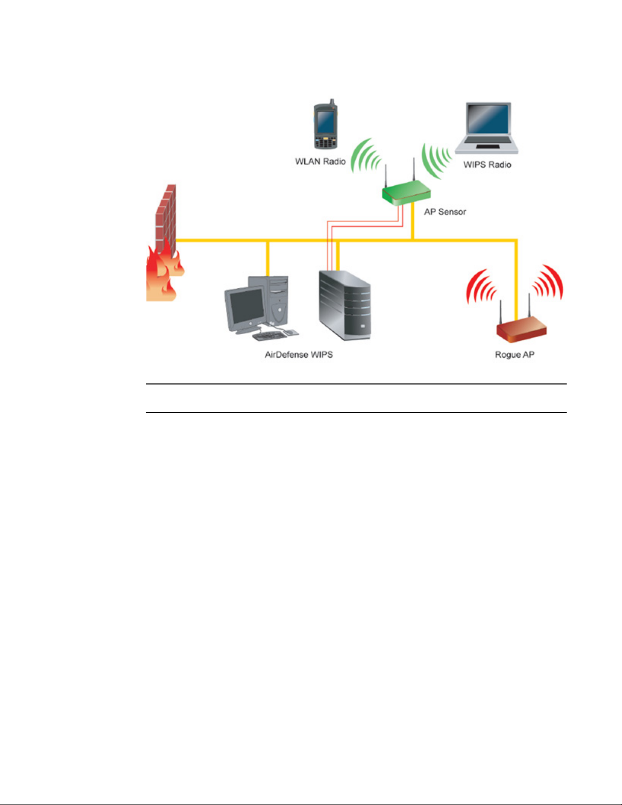
An access point radio can function as a sensor and upload sensor mode operation information to a
dedicated WIPS server. WIPS is not supported on a WLAN basis, rather sensor functionality is
supported on the access point radio(s) available to each WLAN. When an access point radio is
functioning as a WIPS sensor, it is able to scan in sensor mode across all channels within the 2.4
and 5.0 GHz bands.
NOTE
Sensor support requires an AirDefense WIPS Server on the network. Sensor functionality is not
provided by the access point alone. The access point works in conjunction with a dedicated WIPS
server.
The following is a network topology illustrating how a sensor functions within an access point
supported wireless network:
Brocade Mobility 7131N-FGR Product Reference Guide 5
53-1001947-01
Feature overview
1
A radio in sensor mode supports three basic features:
NOTE
The functions described below are conducted on the WIPS server side, not on the access point.
• Wireless Termination - The access point attempts to force an unwanted (or unauthorized)
connection to disconnect.
• Wireless Sniffing - All received frames are reported to the WIPS server. This feature provides
the WIPS server with visibility into the activity on the wireless network. The WIPS server
processes the received traffic and provides the IT administrator with useful information about
the 802.11 RF activities in the enterprise.
• Spectrum Analysis - The data needed to provide the current RF Spectrum is provided to the
WIPS server. The access point does not display the data, but it is available to the WIPS server.
Spectrum analysis can operate only when there are no WLAN radios configured. The WIPS
daemon and server are responsible for limiting operation only when there is no radio in WLAN
mode. When a configuration change is made at the AP, the Spectrum Analysis operation stops.
• Live View- The WIPS application provides a live view of the sensors, APs and MUs operating in
a WLAN. Live view support exists throughout the WIPS application, wherever a device icon
appears in an information panel or navigation tree. Access Live View by right-clicking on the
device, which automatically limits the data to the specific device your choose.
Sensor radios can be tuned to channels in both the 2.4GHz and 5.0 GHz band. The channels in use
by a given radio are defined by the WIPS application. There is no need to explicitly set a band for a
sensor radio. Instead, select either default values or specific channels. Specific channels can be in
either band.
6 Brocade Mobility 7131N-FGR Product Reference Guide
53-1001947-01

Feature overview
CAUTION
Users cannot define a radio as a sensor when one of the access point radios is functioning as a
rogue AP detector. To use one of the radios as a WIPS sensor, you must disable its current
detector method(s) first, then set the radio for WIPS sensor support. For information on disabling
rogue AP detection, see “Configuring rogue AP detection” on page 195.
1
Mesh Roaming Client
Enable the Mesh Roaming Client feature (using the access point’s CLI) to allow a client bridge to
associate in the same manner as a regular mesh client bridge. After an initial (single) association,
the client bridge will not attempt additional associations. Since STP will be disabled, the
association forwards data as soon as the association attempt is successful. When Mesh Roaming
Client is enabled, base bridge mode is not supported to avoid a loop within the mesh topology.
Thus, the Mesh Roaming Client is always an end point (by design) within the mesh wireless
topology. The base bridge will need STP disabled to immediately begin forwarding data when a
roaming client bridge associates.
Dual mode radio options
When the access point is manufactured as a dual-radio access point, as is the case with the
Brocade Mobility 7131N-FGR Access Point, the access point enables you to configure one radio for
802.11a/n support, and the other for 802.11b/g/n support.
The two models available to the Brocade Mobility 7131N-FGR Access Point series are:
• BR-7131N-66040-FGR (802.11an and 802.11bgn capable)
• BR-7131N-66040-FWW (802.11an and 802.11bgn capable)
For detailed information, see “Setting the WLAN’s radio configuration” on page 137.
Separate LAN and WAN ports
The access point has one LAN (GE1/POE) port and one WAN (GE2) port, each with their own MAC
address. The access point must manage all data traffic over the LAN connection carefully as either
a DHCP client, BOOTP client, DHCP server or using a static IP address. The access point can only
use a Power-over-Ethernet device when connected to the LAN port.
For detailed information on configuring the LAN port, see “Configuring the LAN interface” on
page 99.
A Wide Area Network (WAN) is a widely dispersed telecommunications network. In a corporate
environment, the WAN port might connect to a larger corporate network. For a small business, the
WAN port might connect to a DSL or cable modem to access the Internet. Regardless, network
address information must be configured for the access point’s intended mode of operation.
For detailed information on configuring the access point’s WAN port, see “Configuring WAN
settings” on page 111.
The LAN and WAN port MAC addresses can be located within the LAN and WAN Stats screens.
Brocade Mobility 7131N-FGR Product Reference Guide 7
53-1001947-01

Feature overview
1
For detailed information on locating the access point’s MAC addresses, see “Viewing WAN
statistics” on page 216 and “Viewing LAN statistics” on page 218. For information on access point
MAC address assignments, see “MAC address assignment” on page 22.
Multiple mounting options
The access point attaches to a wall, mounts under a ceiling or above a ceiling (attic). Choose a
mounting option based on the physical environment of the coverage area. Do not mount the
access point in a location that has not been approved in a radio coverage site survey.
For detailed information on the mounting options available, see “Mounting a Brocade Mobility
7131N-FGR Access Point” on page 27.
Antenna support for 2.4 GHz and 5 GHz radios
The access point supports several 802.11a/n and 802.11b/g/n radio antennas. Select the
antenna best suited to the radio transmission requirements of your coverage area.
For an exhaustive overview of the antennas and associated components supported by the Brocade
access point family, refer to “Antenna options” on page 25.
Sixteen configurable WLANs
A Wireless Local Area Network (WLAN) is a data-communications system that flexibly extends the
functionalities of a wired LAN. A WLAN does not require lining up devices for line-of-sight
transmission, and are thus, desirable for wireless networking. Roaming users can be handed off
from one access point to another like a cellular phone system. WLANs can therefore be configured
around the needs of specific groups of users, even when they are not in physical proximity. Sixteen
WLANs are configurable on each access point.
To enable and configure WLANs on an access point radio, see “Enabling Wireless LANs (WLANs)”
on page 119.
Support for 4 BSSIDs per radio
The access point supports four BSSIDs per radio. Each BSSID has a corresponding MAC address.
The first MAC address corresponds to BSSID #1. The MAC addresses for the other three BSSIDs
(BSSIDs #2, #3, #4) are derived by adding 1, 2, 3, respectively, to the radio MAC address.
If the radio MAC address displayed on the Radio Settings screen is 00:23:68:72:20:DC, then the
BSSIDs for that radio will have the following MAC addresses:
8 Brocade Mobility 7131N-FGR Product Reference Guide
53-1001947-01

Feature overview
BSSID MAC Address Hexadecimal Addition
BSSID #1 00:23:68:72:20:DC Same as Radio MAC address
BSSID #2 00:23:68:72:20:DD Radio MAC address +1
BSSID #3 00:23:68:72:20:DE Radio MAC address +2
BSSID #4 00:23:68:72:20:DF Radio MAC address +3
For detailed information on strategically mapping BSSIDs to WLANs, see “Configuring the
802.11a/n or 802.11b/g/n radio” on page 142. For information on access point MAC address
assignments, see “MAC address assignment” on page 22.
1
Quality of Service (QoS) support
The QoS implementation provides applications running on different wireless devices a variety of
priority levels to transmit data to and from the access point. Equal data transmission priority is fine
for data traffic from applications such as Web browsers, file transfers or email, but is inadequate
for multimedia applications.
Voice over Internet Protocol (VoIP), video streaming and interactive gaming are highly sensitive to
latency increases and throughput reductions. These forms of higher priority data traffic can
significantly benefit from the QoS implementation.The WiFi Multimedia QOS Extensions (WMM)
implementation used by the shortens the time between transmitting higher priority data traffic and
is thus desirable for multimedia applications. In addition, U-APSD (WMM Power Save) is also
supported.
WMM defines four access categories—voice, video, best effort and background—to prioritize traffic
for enhanced multimedia support.
For detailed information on configuring QoS support, see “Setting the WLAN Quality of Service
(QoS) policy” on page 129.
Industry leading data security
The Brocade Mobility 7131N-FGR Access Point a unique set of encryption and authentication
techniques to protect the data transmitting on the WLAN.
The following authentication techniques are supported:
• EAP Authentication
The following encryption techniques are supported:
• WPA2-CCMP (802.11i) encryption
In addition, the access point supports the following additional security features:
• Firewall security
• VPN tunnels
• Content filtering
For an overview on the encryption and authentication schemes available , refer to “Configuring
Access Point Security” on page 161.
Brocade Mobility 7131N-FGR Product Reference Guide 9
53-1001947-01

Feature overview
1
EAP Authentication
The Extensible Authentication Protocol (EAP) feature provides access points and their associated
MUs an additional measure of security for data transmitted over the wireless network. Using EAP,
authentication between devices is achieved through the exchange and verification of certificates.
EAP is a mutual authentication method whereby both the MU and AP are required to prove their
identities. Using EAP, the user loses device authentication if the server cannot provide proof of
device identification.
Using EAP, a user requests connection to a WLAN through the access point. The access point then
requests the identity of the user and transmits that identity to an authentication server. The server
prompts the AP for proof of identity (supplied to the by the user) and then transmits the user data
back to the server to complete the authentication process.
An MU is not able to access the network if not authenticated. When configured for EAP support, the
access point displays the MU as an EAP station.
EAP is only supported on mobile devices running Windows XP, Windows 2000 (using Service Pack
#4) and Windows Mobile 2003. Refer to the system administrator for information on configuring a
Radius Server for EAP (802.1x) support.
For detailed information on EAP configurations, see “Configuring 802.1x EAP settings” on
page 165.
WPA2-CCMP (802.11i) encryption
WPA2 is a newer 802.11i standard that provides even stronger wireless security than Wi-Fi
Protected Access (WPA) and WEP. Counter-mode/CBC-MAC Protocol (CCMP) is the security
standard used by the Advanced Encryption Standard (AES). AES serves the same function TKIP
does for WPA-TKIP. CCMP computes a Message Integrity Check (MIC) using the proven Cipher
Block Message Authentication Code (CBC-MAC) technique. Changing just one bit in a message
produces a totally different result.
WPA2-CCMP is based on the concept of a Robust Security Network (RSN), which defines a
hierarchy of keys with a limited lifetime (similar to TKIP). Like TKIP, the keys the administrator
provides are used to derive other keys. Messages are encrypted using a 256-bit secret key and a
256-bit block of data. The end result is an encryption scheme as secure as any the access point
provides.
For detailed information on WPA2-CCMP, see “Configuring WPA2-CCMP (802.11i)” on page 169.
Firewall security
A firewall keeps personal data in and hackers out. The access point’s firewall prevents suspicious
Internet traffic from proliferating the access point managed network. The access point performs
Network Address Translation (NAT) on packets passing to and from the WAN port. This combination
provides enhanced security by monitoring communication with the wired network.
For detailed information on configuring the access point’s firewall, see “Configuring firewall
settings” on page 171.
10 Brocade Mobility 7131N-FGR Product Reference Guide
53-1001947-01

Feature overview
1
VPN tunnels
Virtual Private Networks (VPNs) are IP-based networks using encryption and tunneling providing
users remote access to a secure LAN. In essence, the trust relationship is extended from one LAN
across the public network to another LAN, without sacrificing security. A VPN behaves like a private
network; however, because the data travels through the public network, it needs several layers of
security. The access point can function as a robust VPN gateway.
For detailed information on configuring VPN security support, see “Configuring VPN tunnels” on
page 178.
Content filtering
Content filtering allows system administrators to block specific commands and URL extensions
from going out through the WAN port. Therefore, content filtering affords system administrators
selective control on the content proliferating the network and is a powerful screening tool. Content
filtering allows the blocking of up to 10 files or URL extensions and allows blocking of specific
outbound requests.
For detailed information on configuring content filtering support, see “Configuring content filtering
settings” on page 192.
VLAN support
A Virtual Local Area Network (VLAN) can electronically separate data on the same AP from a single
broadcast domain into separate broadcast domains. By using a VLAN, you can group by logical
function instead of physical location. There are 16 VLANs supported on the access point. An
administrator can map up to 16 WLANs to 16 VLANs and enable or disable dynamic VLAN
assignment. In addition to these 16 VLANs, the access point supports dynamic, user-based, VLANs
when using EAP authentication.
VLANs enable organizations to share network resources in various network segments within large
areas (airports, shopping malls, etc.). A VLAN is a group of clients with a common set of
requirements independent of their physical location. VLANs have the same attributes as physical
LANs, but they enable administrators to group clients even when they are not members of the
same network segment.
For detailed information on configuring VLAN support, see “Configuring VLAN support” on
page 102.
Multiple management accessibility options
The access point can be accessed and configured using one of the following:
• Java-Based Web UI
• Human readable config file (imported via SFTP)
• MIB (Management Information Base)
• Command Line Interface (CLI) accessed via RS-232 or Telnet. Use the access point’s DB-9
serial port for direct access to the command-line interface from a PC. Use a Null-Modem cable
for the best fitting connection.
Brocade Mobility 7131N-FGR Product Reference Guide 11
53-1001947-01

Feature overview
1
Updatable firmware
Brocade periodically releases updated versions of device firmware to the Brocade Web site. If the
firmware version displayed on the System Settings screen (see “Configuring system settings” on
page 56) is older than the version on the Web site, Brocade recommends updating the access
point to the latest firmware version for full feature functionality.
For detailed information on updating the firmware using SFTP, see “Updating device firmware” on
page 94.
Programmable SNMP v1/v2/v3 trap support
Simple Network Management Protocol (SNMP) facilitates the exchange of management
information between network devices. SNMP uses Management Information Bases (MIBs) to
manage the device configuration and monitor Internet devices in remote locations. MIB
information accessed via SNMP is defined by a set of managed objects called Object Identifiers
(OIDs). An OID is used to uniquely identify each object variable of a MIB.
SNMP allows a network administrator to configure the access point, manage network performance,
find and solve network problems, and plan network growth. The access point supports SNMP
management functions for gathering information from its network components. The access point’s
download site contains MIB files supporting the access point:
The access point’s SNMP agent functions as a command responder and is a multilingual agent
responding to SNMPv1, v2c and v3 managers (command generators). The factory default
configuration maintains SNMPv1/2c support of community names, thus providing backward
compatibility.
For detailed information on configuring SNMP traps, see “Configuring SNMP settings” on page 75.
MU-MU Transmission Disallow
The access point’s MU-MU Disallow feature prohibits MUs from communicating with each other
even if on the same WLAN, assuming one of the WLAN’s is configured to disallow MU-MU
communication. Therefore, if an MU’s WLAN is configured for MU-MU disallow, it will not be able to
communicate with any other MUs connected to this access point.
For detailed information on configuring an WLAN to disallow MU to MU communications, see
“Creating/editing individual WLANs” on page 121.
Voice prioritization
Each access point WLAN has the capability of having its QoS policy configured to prioritize the
network traffic requirements for associated MUs. A WLAN QoS page is available for each enabled
WLAN on either the 802.11a/n or 802.11b/g/n radio.
Use the QoS page to enable voice prioritization for devices to receive the transmission priority they
may not normally receive over other data traffic. Voice prioritization allows the access point to
assign priority to voice traffic over data traffic, and (if necessary) assign legacy voice supported
devices (non WMM supported voice devices) additional priority.
For detailed information on configuring voice prioritization over other voice enabled devices, see
“Setting the WLAN Quality of Service (QoS) policy” on page 129.
12 Brocade Mobility 7131N-FGR Product Reference Guide
53-1001947-01

Feature overview
1
Support for CAM and PSP MUs
The access point supports both CAM and PSP powered MUs. CAM (Continuously Aware Mode) MUs
leave their radios on continuously to hear every beacon and message transmitted. These systems
operate without any adjustments by the access point.
A beacon is a uniframe system packet broadcast by the AP to keep the network synchronized. A
beacon includes the ESSID, MAC address, Broadcast destination addresses, a time stamp, a DTIM
(Delivery Traffic Indication Message) and the TIM (Traffic Indication Map).
PSP (Power Save Polling) MUs power off their radios for short periods. When a MU in PSP mode
associates with an access point, it notifies the access point of its activity status. The access point
responds by buffering packets received for the MU. PSP mode is used to extend an MU’s battery
life by enabling the MU to “sleep” during periods of inactivity.
Statistical displays
The access point can display robust transmit and receive statistics for the WAN and LAN ports.
WLAN stats can be displayed collectively and individually for enabled WLANs. Transmit and receive
statistics are available for the access point’s 802.11a/n and 802.11b/g/n radios. An advanced
radio statistics page is also available to display retry histograms for specific data packet retry
information.
Associated MU stats can be displayed collectively and individually for specific MUs. An echo (ping)
test is also available to ping specific MUs to assess association strength. Finally, the access point
can detect and display the properties of other APs detected within its radio coverage area. The type
of AP detected can be displayed as well as the properties of individual APs.
For detailed information on available access point statistical displays and the values they
represent, see “Monitoring Statistics” on page 215.
Transmit power control
The access point has a configurable power level for each radio. This enables the network
administrator to define the antenna’s transmission power level in respect to the access point’s
placement or network requirements as defined in the site survey.
For detailed information on setting the radio transmit power level, see “Configuring the 802.11a/n
or 802.11b/g/n radio” on page 142.
Advanced event logging capability
The access point periodically logs system events. Logging events is useful in assessing the
throughput and performance of the access point or troubleshooting problems on the access point
managed Local Area Network (LAN).
For detailed information on access point events, see “Logging configuration” on page 90.
Brocade Mobility 7131N-FGR Product Reference Guide 13
53-1001947-01

Feature overview
1
Configuration file import/export functionality
Configuration settings for an access point can be downloaded from the current configuration of
another access point. This affords the administrator the ability to save the current configuration
before making significant changes or restoring a default configuration. A configuration file from a
dual radio Brocade Mobility 7131N-FGR Access Point can be imported to another dual radio model
Brocade Mobility 7131N-FGR Access Point.
For detailed information on importing or exporting configuration files, see “Importing/exporting
configurations” on page 92.
Default configuration restoration
The access point can restore its default configuration or a partial default configuration (with the
exception of current WAN and SNMP settings). Restoring the default configuration is a good way to
create new WLANs if the MUs the access point supports have been moved to different radio
coverage areas.
For detailed information on restoring a default or partial default configuration, see “Configuring
system settings” on page 56.
DHCP support
The access point can use Dynamic Host Configuration Protocol (DHCP) to obtain a leased IP
address and configuration information from a remote server. DHCP is based on the BOOTP protocol
and can coexist or interoperate with BOOTP. Configure the access point to send out a DHCP
request searching for a DHCP/BOOTP server to acquire HTML, firmware or network configuration
files when the access point boots. Because BOOTP and DHCP interoperate, whichever responds
first becomes the server that allocates information.
The access point can be set to only accept replies from DHCP or BOOTP servers or both (this is the
default setting). Disabling DHCP disables BOOTP and DHCP and requires network settings to be set
manually. If running both DHCP and BOOTP, do not select BOOTP Only. BOOTP should only be used
when the server is running BOOTP exclusively.
The DHCP client automatically sends a DHCP request at an interval specified by the DHCP server to
renew the IP address lease as long as the access point is running (this parameter is programmed
at the DHCP server). For example: Windows 2000 servers typically are set for 3 days.
Mesh networking
Utilize the new mesh networking functionality to allow the access point to function as a bridge to
connect two Ethernet networks or as a repeater to extend your network’s coverage area without
additional cabling. Mesh networking is configurable in two modes. It can be set in a wireless client
bridge mode and/or a wireless base bridge mode (which accepts connections from client bridges).
These two modes are not mutually exclusive.
In client bridge mode, the access point scans to find other access points using the selected
WLAN’s ESSID. The access point must go through the association and authentication process to
establish a wireless connection. The mesh networking association process is identical to the
access point’s MU association process. Once the association/authentication process is complete,
14 Brocade Mobility 7131N-FGR Product Reference Guide
53-1001947-01

Feature overview
the wireless client adds the connection as a port on its bridge module. This causes the access
point (in client bridge mode) to begin forwarding configuration packets to the base bridge. An
access point in base bridge mode allows the access point radio to accept client bridge
connections.
The two bridges communicate using the Spanning Tree Protocol (STP). The spanning tree
determines the path to the root and detects if the current connection is part of a network loop with
another connection. Once the spanning tree converges, both access points begin learning which
destinations reside on which side of the network. This allows them to forward traffic intelligently.
After the access point (in client bridge mode) establishes at least one wireless connection, it will
begin beaconing and accepting wireless connections (if configured to support mobile users). If the
access point is configured as both a client bridge and a base bridge, it begins accepting client
bridge connections. In this way, the mesh network builds itself over time and distance.
Once the access point (in client bridge mode) establishes at least one wireless connection, it
establishes other wireless connections in the background as they become available. In this way,
the access point can establish simultaneous redundant links. An access point (in client bridge
mode) can establish up to 3 simultaneous wireless connections with other access points. A client
bridge always initiates the connections and the base bridge is always the acceptor of the mesh
network data proliferating the network.
Since each access point can establish up to 3 simultaneous wireless connections, some of these
connections may be redundant. In that case, the STP algorithm determines which links are the
redundant links and disables the links from forwarding.
1
For an overview on mesh networking as well as details on configuring the access point’s mesh
networking functionality, see “Configuring Mesh Networking” on page 519.
Additional LAN subnet
In a typical retail or small office environment (wherein a wireless network is available along with a
production WLAN) it is often necessary to segment a LAN into two subnets. Consequently, a second
LAN is required to “segregate” wireless traffic.
The access point has a second LAN subnet enabling administrators to segment the access point’s
LAN connection into two separate networks. The main access point LAN screen now allows the
user to select either LAN1 or LAN2 as the active LAN over the access point’s Ethernet port. Both
LANs can still be active at any given time, but only one can transmit over the access point’s
physical LAN connection. Each LAN has a separate configuration screen (called LAN 1 and LAN 2
by default) accessible under the main LAN screen. The user can rename each LAN as necessary.
Additionally, each LAN can have its own Ethernet Type Filter configuration, and subnet access
(HTTP, SSH, SNMP and telnet) configuration.
For detailed information on configuring the access point for additional LAN subnet support, see
“Configuring the LAN interface” on page 99.
On-board Radius Server authentication
The access point can function as a Radius Server to provide user database information and user
authentication. Several new screens have been added to the access point’s menu tree to configure
Radius server authentication and configure the local user database and access policies. The new
Radius Server functionality allows an administrator to define the data source, authentication type
and associate digital certificates with the authentication scheme. The LDAP screen allows the
administrator to configure an external LDAP Server for use with the access point. A new Access
Brocade Mobility 7131N-FGR Product Reference Guide 15
53-1001947-01

Feature overview
1
Policy screen enables the administrator to set WLAN access based on user groups defined within
the User Database screen. Each user is authorized based on the access policies applicable to that
user. Access policies allow an administrator to control access to a user groups based on the WLAN
configurations.
For detailed information on configuring the access point for AAA Radius Server support, see
“Configuring user authentication” on page 201.
Hotspot support
The access point allows hotspot operators to provide user authentication and accounting without a
special client application. The access point uses a traditional Internet browser as a secure
authentication device. The access point issues an IP address to the user using a DHCP server,
authenticates the user and grants the user to access the Internet.
If a tourist visits a public hotspot and wants to browse a Web page, they boot their laptop and
associate with a local Wi-Fi network by entering a valid SSID. They start a browser, and the
hotspot’s access controller forces the un-authenticated user to a Welcome page (from the hotspot
operator) that allows the user to login with a username and password. In order to send a redirected
page (a login page), a TCP termination exists locally on the access point. Once the login page
displays, the user enters their credentials. The access point connects to the Radius server and
determines the identity of the connected wireless user. Thus, allowing the user to access the
Internet once successfully authenticated.
For detailed information on configuring the access point for Hotspot support, see “Configuring
WLAN hotspot support” on page 133.
Routing Information Protocol (RIP)
RIP is an interior gateway protocol that specifies how routers exchange routing-table information.
The parent Router screen also allows the administrator to select the type of RIP and the type of RIP
authentication used.
For detailed information on configuring RIP functionality as part of the access point’s Router
functionality, see “Setting the RIP configuration” on page 154.
Manual date and time settings
As an alternative to defining a NTP server to provide access point system time, the access point
can now have its date and time set manually. A new Manual Date/Time Setting screen can be used
to set the time using a Year-Month-Day HH:MM:SS format.
For detailed information on manually setting the access point’s system time, see “Configuring
Network Time Protocol (NTP)” on page 88.
Dynamic DNS
The access point supports the Dynamic DNS service. Dynamic DNS (or DynDNS) is a feature
offered by www.dyndns.com allowing the mapping of domain names to dynamically assigned IP
addresses. When the dynamically assigned IP address of a client changes, the new IP address is
sent to the DynDNS service and traffic for the specified domain(s) is routed to the new IP address.
For information on configuring Dynamic DNS, see “Configuring Dynamic DNS” on page 118.
16 Brocade Mobility 7131N-FGR Product Reference Guide
53-1001947-01

Feature overview
1
Auto negotiation
Auto negotiation enables the access point to automatically exchange information about data
transmission speed and duplex capabilities. Auto negotiation is helpful when using the access
point in an environment where different devices are connected and disconnected on a regular
basis. For information on configuring the auto negotiation feature, see “Configuring the LAN
interface” on page 99 or “Configuring WAN settings” on page 111.
Adaptive AP
An adaptive AP (AAP) is an access point that can adopt like an access port (L3). The management
of an AAP is conducted by a switch, once the access point connects to a A Brocade Mobility
RFS7000-GR Controller and receives its AAP configuration.
An AAP provides:
• local 802.11 traffic termination
• local encryption/decryption
• local traffic bridging
• the tunneling of centralized traffic to the wireless switch
For a information overview of the adaptive AP feature as well as how to configure it, refer to
“Adapt ive A P” on page 545.
Rogue AP enhancements
The access point can scan for rogues over all channels on both of the access point’s radio bands.
The switching of radio bands is based on a timer with no user intervention required.
For information on configuring the access point for Rogue AP support, see “Configuring rogue AP
detection” on page 195.
Radius time-based authentication
An external server maintains a users and groups database used by the access point for access
permissions. Various kinds of access policies can be applied to each group. Individual groups can
be configured with their own time-based access policy. Each group’s policy has a user defined
interval defining the days and hours access is permitted. Authentication requests for users
belonging to the group are honored only during these defined hourly intervals.
For more information on defining access point access policies by group, see “Defining user access
permissions by group” on page 211.
QBSS support
Each access point radio can be configured to optionally allow the access point to communicate
channel usage data to associated devices and define the beacon interval used for channel
utilization transmissions. The QBSS load represents the percentage of time the channel is in
use by the access point and the access point’s station count. This information is very helpful in
assessing the access point’s overall load on a channel, its availability for additional device
associations and multi media traffic support.
Brocade Mobility 7131N-FGR Product Reference Guide 17
53-1001947-01

Theory of operations
1
For information on enabling QBSS and defining the channel utilization transmission interval,
see “Configuring the 802.11a/n or 802.11b/g/n radio” on page 142.
Theory of operations
To understand access point management and performance alternatives, users need familiarity
with functionality and configuration options. The access point includes features for different
interface connections and network management.
The access point uses electromagnetic waves to transmit and receive electric signals without
wires. Users communicate with the network by establishing radio links between mobile units (MUs)
and access points.
The access point uses DSSS (direct sequence spread spectrum) to transmit digital data from one
device to another. A radio signal begins with a carrier signal that provides the base or center
frequency. The digital data signal is encoded onto carriers using a DSSS chipping algorithm. The
radio signal propagates into the air as electromagnetic waves. A receiving antenna (on the MU) in
the path of the waves absorbs the waves as electrical signals. The receiving MU interprets
(demodulates) the signal by reapplying the direct sequence chipping code. This demodulation
results in the original digital data.
The access point uses its environment (the air and certain objects) as the transmission
medium.The access point can either transmit in the 2.4 to 2.5-GHz frequency range (802.11b/g/n
radio) or the 5 GHz frequency range (802.11a/n radio), the actual range is country-dependent.
Brocade devices, like other Ethernet devices, have unique, hardware encoded Media Access
Control (MAC) or IEEE addresses. MAC addresses determine the device sending or receiving data.
A MAC address is a 48-bit number written as six hexadecimal bytes separated by colons. For
example: 00:A0:F8:24:9A:C8 Also see the following:
• Wireless coverage
• MAC layer bridging
• Content filtering
• DHCP support
• Media types
• Direct-sequence spread spectrum
• MU association process
• Operating modes
• Management access options
• MAC address assignment
Wireless coverage
An access point establishes an average communication range with MUs called a Basic Service Set
(BSS) or cell. When in a particular cell, the MU associates and communicates with the access point
supporting the radio coverage area of that cell. Adding access points to a single LAN establishes
more cells to extend the range of the network. Configuring the same ESSID (Extended Service Set
Identifier) on all access points makes them part of the same Wireless LAN.
18 Brocade Mobility 7131N-FGR Product Reference Guide
53-1001947-01
 Loading...