

Page 1

53-1002517-01
14 May 2012
Brocade Mobility 7131
Access Point
®
Product Reference Guide
Supporting software release 4.4.0.0 and later
Page 2

Copyright © 2012 Brocade Communications Systems, Inc. All Rights Reserved.
Brocade, Brocade Assurance, the B-wing symbol, DCX, Fabric OS, MLX, SAN Health, VCS, and VDX are registered trademarks, and
AnyIO, Brocade One, CloudPlex, Effortless Networking, ICX, NET Health, OpenScript, and The Effortless Network are trademarks of
Brocade Communications Systems, Inc., in the United States and/or in other countries. Other brands, products, or service names
mentioned may be trademarks of their respective owners.
Notice: This document is for informational purposes only and does not set forth any warranty, expressed or implied, concerning
any equipment, equipment feature, or service offered or to be offered by Brocade. Brocade reserves the right to make changes to
this document at any time, without notice, and assumes no responsibility for its use. This informational document describes
features that may not be currently available. Contact a Brocade sales office for information on feature and product availability.
Export of technical data contained in this document may require an export license from the United States government.
The authors and Brocade Communications Systems, Inc. shall have no liability or responsibility to any person or entity with
respect to any loss, cost, liability, or damages arising from the information contained in this book or the computer programs that
accompany it.
The product described by this document may contain “open source” software covered by the GNU General Public License or other
open source license agreements. To find out which open source software is included in Brocade products, view the licensing
terms applicable to the open source software, and obtain a copy of the programming source code, please visit
http://www.brocade.com/support/oscd.
Brocade Communications Systems, Incorporated
Corporate and Latin American Headquarters
Brocade Communications Systems, Inc.
130 Holger Way
San Jose, CA 95134
Tel: 1-408-333-8000
Fax: 1-408-333-8101
E-mail: info@brocade.com
European Headquarters
Brocade Communications Switzerland Sàrl
Centre Swissair
Tour B - 4ème étage
29, Route de l'Aéroport
Case Postale 105
CH-1215 Genève 15
Switzerland
Tel: +41 22 799 5640
Fax: +41 22 799 5641
E-mail: emea-info@brocade.com
Asia-Pacific Headquarters
Brocade Communications Systems China HK, Ltd.
No. 1 Guanghua Road
Chao Yang District
Units 2718 and 2818
Beijing 100020, China
Tel: +8610 6588 8888
Fax: +8610 6588 9999
E-mail: china-info@brocade.com
Asia-Pacific Headquarters
Brocade Communications Systems Co., Ltd. (Shenzhen WFOE)
Citic Plaza
No. 233 Tian He Road North
Unit 1308 – 13th Floor
Guangzhou, China
Tel: +8620 3891 2000
Fax: +8620 3891 2111
E-mail: china-info@brocade.com
Document History
Title Publication number Summary of changes Date
Brocade Mobility 7131 Access Point
Product Reference Guide
53-1002517-01 New document May 2012
Page 3

Contents
About This Guide
In this chapter . . . . . . . . . . . . . . . . . . . . . . . . . . . . . . . . . . . . . . . . . . . . xi
Supported hardware and software . . . . . . . . . . . . . . . . . . . . . . . . . . . xi
Document Conventions . . . . . . . . . . . . . . . . . . . . . . . . . . . . . . . . . . . . xi
Text formatting . . . . . . . . . . . . . . . . . . . . . . . . . . . . . . . . . . . . . . . . xi
Notes. . . . . . . . . . . . . . . . . . . . . . . . . . . . . . . . . . . . . . . . . . . . . . . xii
Related publications . . . . . . . . . . . . . . . . . . . . . . . . . . . . . . . . . . . . . . xii
Getting technical help. . . . . . . . . . . . . . . . . . . . . . . . . . . . . . . . . . . . . xii
Chapter 1 Introduction
In this chapter . . . . . . . . . . . . . . . . . . . . . . . . . . . . . . . . . . . . . . . . . . . . 1
New Features. . . . . . . . . . . . . . . . . . . . . . . . . . . . . . . . . . . . . . . . . . . . . 2
Power Management Antenna Configuration File. . . . . . . . . . . . . 2
Hotspot Customization . . . . . . . . . . . . . . . . . . . . . . . . . . . . . . . . . 3
WAN Failover . . . . . . . . . . . . . . . . . . . . . . . . . . . . . . . . . . . . . . . . . 3
Proxy ARP Support . . . . . . . . . . . . . . . . . . . . . . . . . . . . . . . . . . . . . 4
Multi Cipher Support . . . . . . . . . . . . . . . . . . . . . . . . . . . . . . . . . . . 4
Dynamic Chain Selection. . . . . . . . . . . . . . . . . . . . . . . . . . . . . . . . 5
Broadcast/Multicast Transmit Rate Control. . . . . . . . . . . . . . . . . 5
Dedicated Sensor Support . . . . . . . . . . . . . . . . . . . . . . . . . . . . . . 5
LED Disable . . . . . . . . . . . . . . . . . . . . . . . . . . . . . . . . . . . . . . . . . . 5
Brocade Mobility 7131 Access Point Product Reference Guide iii
53-1002517-01
Page 4

Feature Overview. . . . . . . . . . . . . . . . . . . . . . . . . . . . . . . . . . . . . . . . . . 6
802.11n Support . . . . . . . . . . . . . . . . . . . . . . . . . . . . . . . . . . . . . . 7
Sensor Support . . . . . . . . . . . . . . . . . . . . . . . . . . . . . . . . . . . . . . . 7
Mesh Roaming Client. . . . . . . . . . . . . . . . . . . . . . . . . . . . . . . . . . . 9
Single or Dual Mode Radio Options . . . . . . . . . . . . . . . . . . . . . . . 9
Separate LAN and WAN Ports . . . . . . . . . . . . . . . . . . . . . . . . . . . . 9
Multiple Mounting Options . . . . . . . . . . . . . . . . . . . . . . . . . . . . . 10
Antenna Support for 2.4 GHz and 5 GHz Radios. . . . . . . . . . . .10
Sixteen Configurable WLANs. . . . . . . . . . . . . . . . . . . . . . . . . . . . 10
Support for 4 BSSIDs per Radio . . . . . . . . . . . . . . . . . . . . . . . . .11
Quality of Service (QoS) Support . . . . . . . . . . . . . . . . . . . . . . . . 11
Industry Leading Data Security. . . . . . . . . . . . . . . . . . . . . . . . . . 11
VLAN Support . . . . . . . . . . . . . . . . . . . . . . . . . . . . . . . . . . . . . . . . 15
Multiple Management Accessibility Options . . . . . . . . . . . . . . .15
Updatable Firmware. . . . . . . . . . . . . . . . . . . . . . . . . . . . . . . . . . .15
Programmable SNMP v1/v2/v3 Trap Support. . . . . . . . . . . . . .16
Power-over-Ethernet Support . . . . . . . . . . . . . . . . . . . . . . . . . . .16
MU-MU Transmission Disallow . . . . . . . . . . . . . . . . . . . . . . . . . . 16
Voice Prioritization . . . . . . . . . . . . . . . . . . . . . . . . . . . . . . . . . . . . 17
Support for CAM and PSP MUs . . . . . . . . . . . . . . . . . . . . . . . . . . 17
Statistical Displays. . . . . . . . . . . . . . . . . . . . . . . . . . . . . . . . . . . . 17
Transmit Power Control . . . . . . . . . . . . . . . . . . . . . . . . . . . . . . . .18
Advanced Event Logging Capability . . . . . . . . . . . . . . . . . . . . . .18
Configuration File Import/Export Functionality . . . . . . . . . . . . .18
Default Configuration Restoration . . . . . . . . . . . . . . . . . . . . . . . 18
DHCP Support . . . . . . . . . . . . . . . . . . . . . . . . . . . . . . . . . . . . . . . 18
Mesh Networking . . . . . . . . . . . . . . . . . . . . . . . . . . . . . . . . . . . . . 19
Additional LAN Subnet. . . . . . . . . . . . . . . . . . . . . . . . . . . . . . . . .19
On-board Radius Server Authentication. . . . . . . . . . . . . . . . . . . 20
Hotspot Support. . . . . . . . . . . . . . . . . . . . . . . . . . . . . . . . . . . . . .20
Routing Information Protocol (RIP) . . . . . . . . . . . . . . . . . . . . . . . 21
Manual Date and Time Settings . . . . . . . . . . . . . . . . . . . . . . . . . 21
Dynamic DNS . . . . . . . . . . . . . . . . . . . . . . . . . . . . . . . . . . . . . . . . 21
Auto Negotiation. . . . . . . . . . . . . . . . . . . . . . . . . . . . . . . . . . . . . . 21
Adaptive AP. . . . . . . . . . . . . . . . . . . . . . . . . . . . . . . . . . . . . . . . . . 21
Rogue AP Enhancements . . . . . . . . . . . . . . . . . . . . . . . . . . . . . .22
Radius Time-Based Authentication. . . . . . . . . . . . . . . . . . . . . . . 22
QBSS Support . . . . . . . . . . . . . . . . . . . . . . . . . . . . . . . . . . . . . . .22
Triple Radio Support . . . . . . . . . . . . . . . . . . . . . . . . . . . . . . . . . .22
IP Filtering. . . . . . . . . . . . . . . . . . . . . . . . . . . . . . . . . . . . . . . . . . .23
MU Rate Limiting . . . . . . . . . . . . . . . . . . . . . . . . . . . . . . . . . . . . .23
Per Radio MU Limit . . . . . . . . . . . . . . . . . . . . . . . . . . . . . . . . . . . 23
Power Setting Configuration . . . . . . . . . . . . . . . . . . . . . . . . . . . . 24
AMSDU Transmission Support . . . . . . . . . . . . . . . . . . . . . . . . . .24
IPSec VPN Support . . . . . . . . . . . . . . . . . . . . . . . . . . . . . . . . . . . 24
iv Brocade Mobility 7131 Access Point Product Reference Guide
53-1002517-01
Page 5

Theory of Operations. . . . . . . . . . . . . . . . . . . . . . . . . . . . . . . . . . . . . .25
Wireless Coverage . . . . . . . . . . . . . . . . . . . . . . . . . . . . . . . . . . . . 25
MAC Layer Bridging . . . . . . . . . . . . . . . . . . . . . . . . . . . . . . . . . . .26
Media Types . . . . . . . . . . . . . . . . . . . . . . . . . . . . . . . . . . . . . . . . .27
Direct-Sequence Spread Spectrum . . . . . . . . . . . . . . . . . . . . . .27
MU Association Process . . . . . . . . . . . . . . . . . . . . . . . . . . . . . . . 27
Operating Modes . . . . . . . . . . . . . . . . . . . . . . . . . . . . . . . . . . . . .28
Management Access Options . . . . . . . . . . . . . . . . . . . . . . . . . . .29
MAC Address Assignment . . . . . . . . . . . . . . . . . . . . . . . . . . . . . .29
Chapter 2 Hardware Installation
In this chapter . . . . . . . . . . . . . . . . . . . . . . . . . . . . . . . . . . . . . . . . . . . 31
Precautions . . . . . . . . . . . . . . . . . . . . . . . . . . . . . . . . . . . . . . . . . . . . .31
Requirements . . . . . . . . . . . . . . . . . . . . . . . . . . . . . . . . . . . . . . . . . . . 31
Package Contents . . . . . . . . . . . . . . . . . . . . . . . . . . . . . . . . . . . . . . . .32
Access Point Placement . . . . . . . . . . . . . . . . . . . . . . . . . . . . . . . . . . . 33
Site Surveys . . . . . . . . . . . . . . . . . . . . . . . . . . . . . . . . . . . . . . . . .33
Antenna Options. . . . . . . . . . . . . . . . . . . . . . . . . . . . . . . . . . . . . . 33
Power Options . . . . . . . . . . . . . . . . . . . . . . . . . . . . . . . . . . . . . . . . . . .35
Power Injector System. . . . . . . . . . . . . . . . . . . . . . . . . . . . . . . . . . . . .35
Installing the Power Injector . . . . . . . . . . . . . . . . . . . . . . . . . . . . 37
Mounting an Mobility 7131 Access Point or
Mobility 7131N Access Point . . . . . . . . . . . . . . . . . . . . . . . . . . . . . . . 38
Wall Mounted Installations . . . . . . . . . . . . . . . . . . . . . . . . . . . . .38
Suspended Ceiling T-Bar Installations . . . . . . . . . . . . . . . . . . . . 41
Above the Ceiling (Plenum) Installations . . . . . . . . . . . . . . . . . .43
LED Indicators . . . . . . . . . . . . . . . . . . . . . . . . . . . . . . . . . . . . . . . . . . . 45
Three Radio Mobility 7131N Access Point LEDs . . . . . . . . . . . .46
Dual Radio (2.4/5 GHz) LEDs . . . . . . . . . . . . . . . . . . . . . . . . . . . 47
Single Radio 2.4 GHz LEDs . . . . . . . . . . . . . . . . . . . . . . . . . . . . .48
Single Radio 5 GHz LEDs. . . . . . . . . . . . . . . . . . . . . . . . . . . . . . .48
Rear LED. . . . . . . . . . . . . . . . . . . . . . . . . . . . . . . . . . . . . . . . . . . .49
Setting Up MUs . . . . . . . . . . . . . . . . . . . . . . . . . . . . . . . . . . . . . . . . . .49
Legacy MUs . . . . . . . . . . . . . . . . . . . . . . . . . . . . . . . . . . . . . . . . .49
802.11n MUs . . . . . . . . . . . . . . . . . . . . . . . . . . . . . . . . . . . . . . . . 49
Chapter 3 Getting Started
In this chapter . . . . . . . . . . . . . . . . . . . . . . . . . . . . . . . . . . . . . . . . . . . 51
Installing the Access Point . . . . . . . . . . . . . . . . . . . . . . . . . . . . . . . . . 51
Configuration Options . . . . . . . . . . . . . . . . . . . . . . . . . . . . . . . . . . . . . 51
Initially Connecting to the Access Point. . . . . . . . . . . . . . . . . . . . . . .52
Connecting to the Access Point using the WAN Port . . . . . . . . .52
Connecting to the Access Point using the LAN Port . . . . . . . . .52
Brocade Mobility 7131 Access Point Product Reference Guide v
53-1002517-01
Page 6

Basic Device Configuration. . . . . . . . . . . . . . . . . . . . . . . . . . . . . . . . .53
Configuring Device Settings . . . . . . . . . . . . . . . . . . . . . . . . . . . .55
Testing Connectivity . . . . . . . . . . . . . . . . . . . . . . . . . . . . . . . . . . .64
Where to Go from Here? . . . . . . . . . . . . . . . . . . . . . . . . . . . . . . .64
Chapter 4 System Configuration
In this chapter . . . . . . . . . . . . . . . . . . . . . . . . . . . . . . . . . . . . . . . . . . .67
Configuring System Settings . . . . . . . . . . . . . . . . . . . . . . . . . . . . . . . 67
Configuring Power Settings. . . . . . . . . . . . . . . . . . . . . . . . . . . . . . . . . 70
Adaptive AP Setup. . . . . . . . . . . . . . . . . . . . . . . . . . . . . . . . . . . . . . . .75
Configuring Data Access. . . . . . . . . . . . . . . . . . . . . . . . . . . . . . . . . . . 77
Managing Certificate Authority (CA) Certificates. . . . . . . . . . . . . . . . 81
Importing a CA Certificate . . . . . . . . . . . . . . . . . . . . . . . . . . . . . . 81
Creating Self Certificates for Accessing the VPN. . . . . . . . . . . .82
Creating a Certificate for Onboard Radius Authentication . . . . 85
Configuring SNMP Settings . . . . . . . . . . . . . . . . . . . . . . . . . . . . . . . . 87
Configuring SNMP Access Control . . . . . . . . . . . . . . . . . . . . . . .92
Enabling SNMP Traps . . . . . . . . . . . . . . . . . . . . . . . . . . . . . . . . .93
Configuring Specific SNMP Traps . . . . . . . . . . . . . . . . . . . . . . . . 95
Configuring SNMP RF Trap Thresholds. . . . . . . . . . . . . . . . . . . .98
Configuring LLDP Settings . . . . . . . . . . . . . . . . . . . . . . . . . . . . . . . . .99
Configuring Network Time Protocol (NTP) . . . . . . . . . . . . . . . . . . . .100
Logging Configuration . . . . . . . . . . . . . . . . . . . . . . . . . . . . . . . . . . . .103
Importing/Exporting Configurations . . . . . . . . . . . . . . . . . . . . . . . .104
Updating Device Firmware . . . . . . . . . . . . . . . . . . . . . . . . . . . . . . . .109
Chapter 5 Network Management
In this chapter . . . . . . . . . . . . . . . . . . . . . . . . . . . . . . . . . . . . . . . . . .115
Configuring the LAN Interface . . . . . . . . . . . . . . . . . . . . . . . . . . . . .115
Configuring VLAN Support . . . . . . . . . . . . . . . . . . . . . . . . . . . . .118
Configuring LAN1 and LAN2 Settings. . . . . . . . . . . . . . . . . . . .121
Configuring WAN Settings. . . . . . . . . . . . . . . . . . . . . . . . . . . . . . . . .127
Configuring Network Address Translation (NAT) Settings . . . .132
Configuring Dynamic DNS . . . . . . . . . . . . . . . . . . . . . . . . . . . . .135
Enabling Wireless LANs (WLANs). . . . . . . . . . . . . . . . . . . . . . . . . . .137
Creating/Editing Individual WLANs. . . . . . . . . . . . . . . . . . . . . .139
Setting the Radio Configuration for a WLAN . . . . . . . . . . . . . .161
Configuring MU Rate Limiting . . . . . . . . . . . . . . . . . . . . . . . . . .176
Configuring Router Settings . . . . . . . . . . . . . . . . . . . . . . . . . . . . . . . 178
Setting the RIP Configuration . . . . . . . . . . . . . . . . . . . . . . . . . .179
Configuring IP Filtering . . . . . . . . . . . . . . . . . . . . . . . . . . . . . . . . . . .181
Applying a Filter to LAN1, LAN2 or a WLAN (1-16). . . . . . . . . .183
IP Filter Configuration - Example. . . . . . . . . . . . . . . . . . . . . . . .184
vi Brocade Mobility 7131 Access Point Product Reference Guide
53-1002517-01
Page 7

Chapter 6 Configuring Access Point Security
In this chapter . . . . . . . . . . . . . . . . . . . . . . . . . . . . . . . . . . . . . . . . . .189
Configuring Security Options . . . . . . . . . . . . . . . . . . . . . . . . . . . . . .190
Setting Passwords. . . . . . . . . . . . . . . . . . . . . . . . . . . . . . . . . . . . . . .190
Resetting the Access Point Password. . . . . . . . . . . . . . . . . . . .192
Enabling Authentication and Encryption Schemes. . . . . . . . . . . . .192
Configuring Kerberos Authentication. . . . . . . . . . . . . . . . . . . . . . . .194
Configuring 802.1x EAP Authentication. . . . . . . . . . . . . . . . . . . . . .196
Configuring WEP Encryption. . . . . . . . . . . . . . . . . . . . . . . . . . . . . . .199
Configuring KeyGuard Encryption . . . . . . . . . . . . . . . . . . . . . . . . . .201
Configuring WPA/WPA2 Using TKIP . . . . . . . . . . . . . . . . . . . . . . . . .203
Configuring WPA2-CCMP (802.11i) . . . . . . . . . . . . . . . . . . . . . . . . .205
Configuring Multi Cipher Support. . . . . . . . . . . . . . . . . . . . . . . . . . .208
Configuring Firewall Settings . . . . . . . . . . . . . . . . . . . . . . . . . . . . . . 210
Configuring LAN to WAN Access . . . . . . . . . . . . . . . . . . . . . . . .212
Configuring Advanced Subnet Access . . . . . . . . . . . . . . . . . . .215
Configuring VPN Tunnels . . . . . . . . . . . . . . . . . . . . . . . . . . . . . . . . .216
Creating a VPN Tunnel between Two Access Points . . . . . . . .219
Configuring Manual Key Settings . . . . . . . . . . . . . . . . . . . . . . .221
Configuring Auto Key Settings . . . . . . . . . . . . . . . . . . . . . . . . . .224
Configuring IKE Key Settings. . . . . . . . . . . . . . . . . . . . . . . . . . .226
VPN Configuration - Example . . . . . . . . . . . . . . . . . . . . . . . . . .229
Viewing VPN Status . . . . . . . . . . . . . . . . . . . . . . . . . . . . . . . . . .230
Configuring Content Filtering Settings. . . . . . . . . . . . . . . . . . . . . . .231
Configuring Rogue AP Detection . . . . . . . . . . . . . . . . . . . . . . . . . . .234
Moving Rogue APs to the Allowed AP List . . . . . . . . . . . . . . . .236
Using MUs to Detect Rogue Devices. . . . . . . . . . . . . . . . . . . . .239
Configuring User Authentication . . . . . . . . . . . . . . . . . . . . . . . . . . .240
Configuring the Radius Server . . . . . . . . . . . . . . . . . . . . . . . . .241
Configuring LDAP Authentication . . . . . . . . . . . . . . . . . . . . . . .242
Configuring a Proxy Radius Server . . . . . . . . . . . . . . . . . . . . . .244
Managing the Local User Database . . . . . . . . . . . . . . . . . . . . .246
Defining User Access Permissions by Group . . . . . . . . . . . . . .248
Chapter 7 Monitoring Statistics
In this chapter . . . . . . . . . . . . . . . . . . . . . . . . . . . . . . . . . . . . . . . . . .253
Viewing WAN Statistics . . . . . . . . . . . . . . . . . . . . . . . . . . . . . . . . . . .253
Viewing LAN Statistics. . . . . . . . . . . . . . . . . . . . . . . . . . . . . . . . . . . .256
Viewing STP Statistics for a LAN . . . . . . . . . . . . . . . . . . . . . . . .258
Viewing IP Filter Statistics for a LAN . . . . . . . . . . . . . . . . . . . . .260
Viewing Wireless Statistics. . . . . . . . . . . . . . . . . . . . . . . . . . . . . . . .261
Viewing WLAN Statistics . . . . . . . . . . . . . . . . . . . . . . . . . . . . . .262
Viewing IP Filter Statistics for a WLAN . . . . . . . . . . . . . . . . . . .265
Brocade Mobility 7131 Access Point Product Reference Guide vii
53-1002517-01
Page 8

Viewing Radio Statistics Summary . . . . . . . . . . . . . . . . . . . . . . . . .266
Viewing Radio Statistics . . . . . . . . . . . . . . . . . . . . . . . . . . . . . .267
Viewing MU Statistics Summary. . . . . . . . . . . . . . . . . . . . . . . . . . . . 271
Viewing MU Details . . . . . . . . . . . . . . . . . . . . . . . . . . . . . . . . . .272
Pinging Individual MUs . . . . . . . . . . . . . . . . . . . . . . . . . . . . . . . 274
MU Authentication Statistics. . . . . . . . . . . . . . . . . . . . . . . . . . . 274
Viewing the Mesh Statistics Summary . . . . . . . . . . . . . . . . . . . . . .275
Viewing Known Access Point Statistics . . . . . . . . . . . . . . . . . . . . . .277
Chapter 8 CLI Reference
In this chapter . . . . . . . . . . . . . . . . . . . . . . . . . . . . . . . . . . . . . . . . . .281
Connecting to the CLI . . . . . . . . . . . . . . . . . . . . . . . . . . . . . . . . . . . .281
Accessing the CLI through the Serial Port . . . . . . . . . . . . . . . .281
Accessing the CLI via Telnet . . . . . . . . . . . . . . . . . . . . . . . . . . .282
Admin and Common Commands . . . . . . . . . . . . . . . . . . . . . . . . . . .282
Network Commands . . . . . . . . . . . . . . . . . . . . . . . . . . . . . . . . . . . . .286
System Commands . . . . . . . . . . . . . . . . . . . . . . . . . . . . . . . . . . . . . .378
Firmware Update Commands . . . . . . . . . . . . . . . . . . . . . . . . . .431
Statistics Commands . . . . . . . . . . . . . . . . . . . . . . . . . . . . . . . . . . . .433
Chapter 9 Configuring Mesh Networking
In this chapter . . . . . . . . . . . . . . . . . . . . . . . . . . . . . . . . . . . . . . . . . .443
Mesh Networking Overview . . . . . . . . . . . . . . . . . . . . . . . . . . . . . . .443
The Client Bridge Association Process . . . . . . . . . . . . . . . . . . .444
Spanning Tree Protocol (STP) . . . . . . . . . . . . . . . . . . . . . . . . . .445
Defining the Mesh Topology . . . . . . . . . . . . . . . . . . . . . . . . . . .445
Mesh Networking and the Two Subnets of the Access Point .446
Normal Operation. . . . . . . . . . . . . . . . . . . . . . . . . . . . . . . . . . . .446
Impact of Importing/Exporting Configurations
to a Mesh Network. . . . . . . . . . . . . . . . . . . . . . . . . . . . . . . . . . .446
Configuring Mesh Networking Support . . . . . . . . . . . . . . . . . . . . . .447
Setting the LAN Configuration for Mesh Networking Support 447
Configuring a WLAN for Mesh Networking Support. . . . . . . . .449
Configuring the Access Point Radio for Mesh Support . . . . . .452
Mesh Network Deployment - Quick Setup. . . . . . . . . . . . . . . . . . . .457
Scenario 1 - Two Base Bridges and One Client Bridge . . . . . .458
Scenario 2 - Two Hop Mesh Network with a
Base Bridge Repeater and a Client Bridge. . . . . . . . . . . . . . . .464
Mesh Networking Frequently Asked Questions. . . . . . . . . . . . . . . .468
Chapter 10 Adaptive AP
In this chapter . . . . . . . . . . . . . . . . . . . . . . . . . . . . . . . . . . . . . . . . . . 471
viii Brocade Mobility 7131 Access Point Product Reference Guide
53-1002517-01
Page 9

Adaptive AP Overview . . . . . . . . . . . . . . . . . . . . . . . . . . . . . . . . . . . .471
Where to Go From Here . . . . . . . . . . . . . . . . . . . . . . . . . . . . . . .472
Adaptive AP Management . . . . . . . . . . . . . . . . . . . . . . . . . . . . .472
Licensing. . . . . . . . . . . . . . . . . . . . . . . . . . . . . . . . . . . . . . . . . . .472
Switch Discovery . . . . . . . . . . . . . . . . . . . . . . . . . . . . . . . . . . . .472
Securing a Configuration Channel Between Switch and AP . . 474
Adaptive AP WLAN Topology . . . . . . . . . . . . . . . . . . . . . . . . . . . 474
Configuration Updates. . . . . . . . . . . . . . . . . . . . . . . . . . . . . . . . 474
Securing Data Tunnels between the Switch and AAP . . . . . . . 474
Adaptive AP Switch Failure . . . . . . . . . . . . . . . . . . . . . . . . . . . .475
Remote Site Survivability (RSS) . . . . . . . . . . . . . . . . . . . . . . . .475
Adaptive Mesh Support . . . . . . . . . . . . . . . . . . . . . . . . . . . . . . . 475
Supported Adaptive AP Topologies . . . . . . . . . . . . . . . . . . . . . . . . . 476
Topology Deployment Considerations . . . . . . . . . . . . . . . . . . . 476
Extended WLANs Only . . . . . . . . . . . . . . . . . . . . . . . . . . . . . . . . 476
Independent WLANs Only . . . . . . . . . . . . . . . . . . . . . . . . . . . . .477
Extended WLANs with Independent WLANs. . . . . . . . . . . . . . .477
Extended WLAN with Mesh Networking . . . . . . . . . . . . . . . . . . 477
How the AP Receives its Adaptive Configuration . . . . . . . . . . . . . . 477
Establishing Basic Adaptive AP Connectivity. . . . . . . . . . . . . . . . . .478
Adaptive AP Configuration. . . . . . . . . . . . . . . . . . . . . . . . . . . . .479
Switch Configuration . . . . . . . . . . . . . . . . . . . . . . . . . . . . . . . . .481
Adaptive AP Deployment Considerations. . . . . . . . . . . . . . . . .483
Sample Switch Configuration File for
IPSec and Independent WLAN . . . . . . . . . . . . . . . . . . . . . . . . .484
Chapter A Technical Specifications
In this appendix. . . . . . . . . . . . . . . . . . . . . . . . . . . . . . . . . . . . . . . . .489
Physical Characteristics . . . . . . . . . . . . . . . . . . . . . . . . . . . . . . . . . .489
Mobility 7131 Access Point Physical Characteristics. . . . . . . .489
Mobility 7131N Access Point Physical Characteristics . . . . . .489
Electrical Characteristics . . . . . . . . . . . . . . . . . . . . . . . . . . . . . . . . .490
Mobility 7131 Access Point Radio Characteristics . . . . . . . . . . . . .490
Mobility 7131N Access Point Radio Characteristics. . . . . . . . . . . .491
Country Codes . . . . . . . . . . . . . . . . . . . . . . . . . . . . . . . . . . . . . . . . . .491
Chapter B Usage Scenarios
In this appendix. . . . . . . . . . . . . . . . . . . . . . . . . . . . . . . . . . . . . . . . .495
Configuring Automatic Updates using a DHCP or Linux BootP Server495
Windows - DHCP Server Configuration . . . . . . . . . . . . . . . . . . .495
Linux - BootP Server Configuration. . . . . . . . . . . . . . . . . . . . . .499
Configuring an IPSEC Tunnel and VPN FAQs . . . . . . . . . . . . . . . . . .501
Configuring a VPN Tunnel Between Two Access Points . . . . . .501
Configuring a Cisco VPN Device . . . . . . . . . . . . . . . . . . . . . . . .505
Frequently Asked VPN Questions . . . . . . . . . . . . . . . . . . . . . . .505
Brocade Mobility 7131 Access Point Product Reference Guide ix
53-1002517-01
Page 10

x Brocade Mobility 7131 Access Point Product Reference Guide
53-1002517-01
Page 11

About This Guide
In this chapter
•Supported hardware and software. . . . . . . . . . . . . . . . . . . . . . . . . . . . . . . . . . xi
•Document Conventions. . . . . . . . . . . . . . . . . . . . . . . . . . . . . . . . . . . . . . . . . . . xi
•Related publications . . . . . . . . . . . . . . . . . . . . . . . . . . . . . . . . . . . . . . . . . . . . xii
•Getting technical help . . . . . . . . . . . . . . . . . . . . . . . . . . . . . . . . . . . . . . . . . . . xii
Supported hardware and software
This guide provides configuration and setup information for the Brocade Mobility 7131 Series
Access Point.
Document Conventions
This section describes text formatting conventions and important notice formats used in this
document.
Text formatting
The narrative-text formatting conventions that are used are as follows:
bold text Identifies command names
italic text Provides emphasis
code text Identifies CLI output
For readability, command names in the narrative portions of this guide are presented in bold; for
example, show version.
Identifies the names of user-manipulated GUI elements
Identifies keywords
Identifies text to enter at the GUI or CLI
Identifies variables
Identifies document titles
Brocade Mobility 7131 Access Point Product Reference Guide xi
53-1002517-01
Page 12

Notes
The following notice statement is used in this manual.
NOTE
A note provides a tip, guidance or advice, emphasizes important information, or provides a reference
to related information.
Related publications
The following Brocade Communications Systems, Inc. document supplements the information in
this guide and can be located at http://www.brocade.com/ethernetproducts.
• Brocade Mobility RFS4000, RFS6000 and RFS7000 CLI Reference Guide - Describes the
Command Line Interface (CLI) and Management Information Base (MIB) commands used to
configure the Brocade wireless controllers.
If you find errors in the guide, send an e-mail to documentation@brocade.com.
Getting technical help
To contact Technical Support, go to http://www.brocade.com/services-support/index.page for the
latest e-mail and telephone contact information.
xii Brocade Mobility 7131 Access Point Product Reference Guide
53-1002517-01
Page 13

Chapter
Introduction
In this chapter
As a standalone access point, the Mobility 7131 Access Point provides small and medium-sized
businesses with a consolidated wired and wireless networking infrastructure, all in a single device.
The integrated router, gateway, firewall, DHCP and AAA Radius servers, VPN, hot-spot gateway and
Power-over-Ethernet (PoE) simplify and reduce the costs associated with networking by eliminating
the need to purchase and manage multiple pieces of equipment.
The access point is also designed to meet the needs of large, distributed enterprises by converging
the functionality of a thick access point and thin access port into a single device. This mode
enables the deployment of a fully featured intelligent access point that can be centrally configured
and managed via a Brocade wireless switch in either corporate headquarters or a network
operations center (NOC). In the event the connection between the access point and the wireless
switch is lost, a Remote Site Survivability (RSS) feature ensures the delivery of uninterrupted
wireless services at the local or remote site. All traffic between the adaptive access points and the
wireless switch is secured though an IPSec tunnel. Additionally, compatibility with Brocade’s RF
Management Suite (RFMS) allows you to centrally plan, deploy, monitor and secure large
deployments.
1
•New Features. . . . . . . . . . . . . . . . . . . . . . . . . . . . . . . . . . . . . . . . . . . . . . . . . . . 2
•Feature Overview. . . . . . . . . . . . . . . . . . . . . . . . . . . . . . . . . . . . . . . . . . . . . . . . 6
•Theory of Operations . . . . . . . . . . . . . . . . . . . . . . . . . . . . . . . . . . . . . . . . . . . . 25
With the introduction of the Mobility 7131 Access Point 4.x firmware baseline, Brocade is also
introducing a new series of Mobility 7131N model access points as a compliment to the existing
Mobility 7131 Access Point family. The new Mobility 7131N model access points support the same
feature set and firmware as existing Mobility 7131 model access points, however Mobility 7131N
Access Points support a three radio model (with the third radio dedicated exclusively for sensor
support). For more information on the three radio Mobility 7131N Access Point, see IP Filtering on
page 1-23.
NOTE
Both the Mobility 7131 Access Point and Mobility 7131N model access points share the same Web
applet (user interface) and installation methods. Therefore, the UI and installation descriptions
within this guide apply to both models. There are instances where this common interface is used
differently to configure various features (radio configuration, power management etc.), however
those differences are carefully noted.
If you are new to using an access point for managing your network, refer to Theory of Operations on
page 1-25 for an overview on wireless networking fundamentals.
Brocade Mobility 7131 Access Point Product Reference Guide 1
53-1002517-01
Page 14

1
New Features
The following features are now available with the introduction of the Mobility 7131N Access Point
hardware and WiNG 4.4 firmware baseline:
• Power Management Antenna Configuration File
• Hotspot Customization
• WAN Failover
• Proxy ARP Support
• Multi Cipher Support
• Dynamic Chain Selection
• Broadcast/Multicast Transmit Rate Control
• Dedicated Sensor Support
• LED Disable
Power Management Antenna Configuration File
With this most recent release of the access point firmware, a Power Management Antenna
Configuration File (PMACF) has been added to the access point firmware that automatically
configures the access point’s radio transmit power based on the antenna type deployed, its
supported gain and the deployed country’s regulatory domain restrictions. The antenna type is
defined using the access point’s CLI by assigning a numerical code representing a particular type
(or category) of antenna. The following are the numerical codes representing available antenna
types: 0-Default antenna, 1-Dual band antenna, 2-Omni antenna, 3-Yagi antenna, 4-Embedded
antenna,
5-Panel antenna, 6-Patch antenna and 7-Sector antenna. The antenna gain can be defined using
either the access point’s CLI, applet or SNMP interfaces.
Once the antenna type and gain are provided, the access point calculates the power range. The
PMACF contains transmit power data for each Brocade approved antenna type. Professional
installers enter the antenna type (using the access point’s CLI interface), and the access point
firmware calculates the transmit power automatically. Therefore, professional installers no longer
need to second guess whether the power is over the maximum allowed level.
NOTE
The antenna type and antenna gain values are maintained by the access point after a power cycle,
and are available in imported or exported configurations.
For information on specifying the antenna type and gain for the 2.4 and 5 GHz radios using the
access point CLI, see br7131>admin(network.wireless.radio.802-11n[2.4 GHz])>set for the access
point’s 2.4 GHz radio and br7131>admin(network.wireless.radio.802-11n[5.0 GHz])>set for the
access point’s 5 GHz radio.
For information on defining the antenna gain using the access point’s GUI applet, see Configuring
the 802.11a/n or 802.11b/g/n Radio on page 5-167 and Configuring the 802.11a/n or
802.11b/g/n Radio on page 5-167.
2 Brocade Mobility 7131 Access Point Product Reference Guide
53-1002517-01
Page 15

1
Hotspot Customization
To date, the default hotspot supported on the access point does not allow users to change the text
on the hotspot portal or the logo for the enterprise where the hotspot is deployed. With this most
recent release of the access point firmware, users now have the ability to customize the
appearance of an access point’s WLAN hotspot pages. The access point’s hotspot feature is
supported by four customer accessible pages (login page, welcome page, failure page, and no
service page) displayed on the client attempting to access the AP’s supported hotspot. These four
pages can be unique to each hotspot supported by one of the access point’s 16 WLANs. The
content of the four hotspot pages can be customized by:
• Altering the text that displays on the screen
• Altering the properties of various screen elements (such as background colors, banner and
logos)
NOTE
The access point allows two logos to be displayed per page. The user has the ability to alter logo
placement and screen banner color schemes.
• Configuring a cascading style sheet (css) to define how hotspot pages display font usage, text
size etc.
• Four different screens are available for customization:
• Login Page – Page used to get user’s credentials.
• Welcome Page – Page displayed when the user successfully logs on.
• Fail Page – Page displayed when the user fails to log on.
• No Service Page – Page displayed when the AP temporarily loses connection to the
authentication server or the adopted wireless controller.
For information on customizing a WLAN’s hotspot display, see Customizing a Hotspot Display on
page 5-156.
For information on the access point’s existing (default) hotspot functionality, see Hotspot Support
on page 1-20.
WAN Failover
With this most recent release of the Mobility 7131N Access Point firmware, a WAN failover feature
has been introduced, since a cellular network infrastructure is completely separate from the
access point’s wired transmission infrastructure.
A WWAN card is a specialized network interface card, allowing a network device to connect,
transmit and receive data over a cellular WAN. The WWAN card uses point to point protocol (PPP) to
connect to an Internet Service Provider (ISP) and access the Internet. PPP is the protocol used for
establishing internet links over dial-up modems, DSL connections, and many other types of
point-to-point links.
The wired WAN is the primary WAN link for a Mobility 7131N Access Point, as long as it is enabled
and connected, and the wireless WAN interface is the secondary link. For a WWAN to be a WAN or
LAN recovery solution, the Mobility 7131N Access Point needs to monitor the link status of the
wired WAN and actively check the health of the WAN connection. If a wired WAN or LAN connection
failure is detected, a Mobility 7131N Access Point immediately establishes the WWAN connection
and updates the default gateway to the WWAN interface.
Brocade Mobility 7131 Access Point Product Reference Guide 3
53-1002517-01
Page 16

1
The WWAN card is detected automatically when inserted into the Mobility 7131N Access Point
express card slot. The card is detected as a USB/Serial device once its modules are loaded. If the
card is inserted before or during module installation, the user has to wait until all the modules are
loaded before the card is operational. These modules are loaded when the Mobility 7131N Access
Point boots up (at runtime). Activate and configure the WWAN card from the access point’s applet
and CLI.
NOTE
The WAN failover feature is only supported on Mobility 7131N Access Point model access points, as
theMobility 7131 model access point does not support the required PCI express card slot.
For more information on configuring a Mobility 7131N Access Point model access point for WAN
failover support, see Configuring WAN Settings on page 5-127.
Proxy ARP Support
With this most recent release of the access point firmware, the access point can respond to ARP
requests on behalf of an associated MU and protect the MU’s network credentials from being
broadcasted on a publicly accessible network.
When Proxy ARP is enabled on the access point (it’s enabled by default), the access point can
make an MU physically located on one network appear part of a different network connected to the
same access point. Proxy AP allows the access point to “hide” an MU’s IP address behind the
access point’s firewall, while still having the MU appear to be on the public network. Proxy ARP
supports both strict and dynamic modes on the access point.
For example, when Proxy ARP is enabled on the access point (it’s disabled by default) and the
access point receives an ARP request (either a wired or wireless request) for the IP address of an
associated MU, the access point responds directly to the request (on behalf of the MU) instead of
broadcasting the ARP request over the publicly accessible wireless network.
When enabled, any system on the wireless network that ARPs for the IP address of an associated
MU will receive an ARP reply from the access point stating the requesting system should be
sending packets destined for the MU to access point instead. In turn, the access point forwards the
requesting packets to the target MU. Through this process, the access point can pass ARP requests
in both directions, making an MU appear to be connected to a public network even though it’s on a
private network hidden behind the access point.
For detailed information on configuring Proxy AP support of the access point, see Enabling Wireless
LANs (WLANs) on page 5-137.
Multi Cipher Support
Beginning with this release, professional installers have the option of deploying both new and
legacy MUs within the same WLAN. Multi cipher support extends the access point’s existing WLAN
security options by allowing dynamic WEP and 802.11i configurations to co-exist, and allowing
multiple security policies to be associated with the same ESSID on different WLANs. Within such an
environment, legacy MUs are capable of WEP, while new MUs are capable of WPA/2-TKIP and
WPA2-CCMP encryption. This particular form of multi cipher (security) support helps maintain the
co-existence of dynamic WEP and 802.11i based environments.
For information on configuring Multi Cipher support, see Configuring Multi Cipher Support on page
6-208.
4 Brocade Mobility 7131 Access Point Product Reference Guide
53-1002517-01
Page 17

1
Dynamic Chain Selection
When enabled, dynamic chain selection forces an access point radio to transmit packets using
legacy transmit rates (11b, 11g and/or 11a rates) using a single transmit chain. Transmissions
utilizing 11n rates (MCS0 - MCS15) continue to use a normal number of transmit chains, which
may be 1, 2, or 3 depending on the configuration and power source. If dynamic chain selection is
disabled, all transmissions utilize the same number of transmit chains. This feature is disabled by
default.
Brocade has determined some of our 802.11abg-based phones don't receive frames transmitted
by the a Mobility 7131 series access point very well if all 3 transmit chains are used. When only a
single transmit chain is used, communication between the access point and the phones works
better. This Brocade phone issue could also exist with other 802.11 legacy devices.
For information on enabling dynamic chain selection using the access point Web applet, see
Configuring the 802.11a/n or 802.11b/g/n Radio on page 5-167.
For information on using the CLI to set the access point’s dynamic chain selection configuration,
see br7131>admin(network.wireless.radio.802-11n[2.4 GHz])>set for the access point’s 2.4 GHz
radio and br7131>admin(network.wireless.radio.802-11n[5.0 GHz])>set for the access point 5
GHz radio.
Broadcast/Multicast Transmit Rate Control
Beginning with this release, professional installers now have the ability to define the access point’s
broadcast/multicast transmission configuration. Traditionally, the access point used the lowest
basic rate for broadcast/multicast transmissions, which was ideal from a range perspective (and
remains the default configuration).
The new enhancement provides an option to increase performance by transmitting
broadcast/multicast group packets at a higher rate (based on the radio’s defined basic data rates).
This option is optimal in environments where the access point’s broadcast/multicast (group
packet) transmission range is secondary to performance. Broadcast/multicast rate control is
configurable from the access point’s GUI applet, CLI and SNMP interfaces.
For information on configuring broadcast/multicast transmit rate control, see Configuring the
802.11a/n or 802.11b/g/n Radio on page 5-167.
Dedicated Sensor Support
Beginning with this release, the access point supports a CLI command enabling an access point
radio to convert to sensor only support. When enabled, only sensor mode radio configurations are
permitted. Radio configurations supporting data (WLAN) support are not configurable using the
access point’s GUI, CLI or SNMP interfaces.
LED Disable
Through extensive field research, Brocade has learned that not all customers wish to deploy an
access point with blinking LEDs. Health care deployments in particular have requested an option to
disable blinking LEDs. With this most recent release of the Mobility 7131N Access Point firmware,
an option has been added to the access point’s GUI applet and CLI to disable blinking LEDs. The
LEDs display and blink default until the disable option is invoked.
Brocade Mobility 7131 Access Point Product Reference Guide 5
53-1002517-01
Page 18

1
For information on disabling the access points LEDs, refer to Configuring System Settings on page
4-67.
Feature Overview
The following legacy features have been carried forward into the 4.x firmware baseline:
• 802.11n Support
• Sensor Support
• Mesh Roaming Client
• Single or Dual Mode Radio Options
• Separate LAN and WAN Ports
• Multiple Mounting Options
• Antenna Support for 2.4 GHz and 5 GHz Radios
• Sixteen Configurable WLANs
• Support for 4 BSSIDs per Radio
• Quality of Service (QoS) Support
• Industry Leading Data Security
• VLAN Support
• Multiple Management Accessibility Options
• Updatable Firmware
• Programmable SNMP v1/v2/v3 Trap Support
• Power-over-Ethernet Support
• MU-MU Transmission Disallow
• Voice Prioritization
• Support for CAM and PSP MUs
• Statistical Displays
• Transmit Power Control
• Advanced Event Logging Capability
• Configuration File Import/Export Functionality
• Default Configuration Restoration
• DHCP Support
• Mesh Networking
• Additional LAN Subnet
• On-board Radius Server Authentication
• Hotspot Support
• Routing Information Protocol (RIP)
• Manual Date and Time Settings
• Dynamic DNS
• Auto Negotiation
6 Brocade Mobility 7131 Access Point Product Reference Guide
53-1002517-01
Page 19

1
• Adaptive AP
• Rogue AP Enhancements
• Radius Time-Based Authentication
• QBSS Support
• Triple Radio Support
• IP Filtering
• MU Rate Limiting
• Per Radio MU Limit
• Power Setting Configuration
• AMSDU Transmission Support
• IPSec VPN Support
802.11n Support
Brocade provides full life-cycle support for either a new or existing 802.11n mobility deployment,
from network design to day-to-day support. For information on deploying your 802.11n radio, see
Configuring the 802.11a/n or 802.11b/g/n Radio on page 5-167.
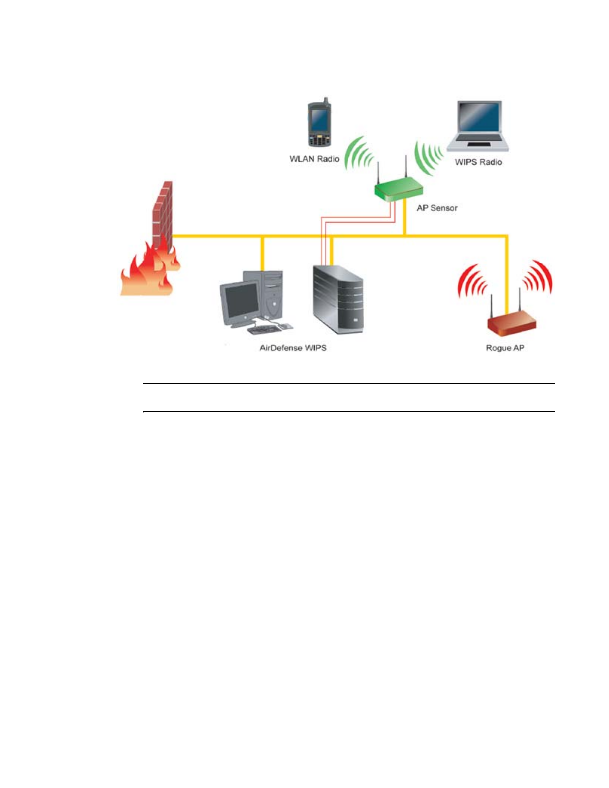
Sensor Support
The Brocade Wireless Intrusion Protection System (WIPS) protects your wireless network, mobile
devices and traffic from attacks and unauthorized access. WIPS provides tools for standards
compliance and around-the-clock 802.11a/b/g wireless network security in a distributed
environment. WIPS allows administrators to identify and accurately locate attacks, rogue devices
and network vulnerabilities in real time and permits both a wired and wireless lockdown of wireless
device connections upon acknowledgement of a threat.
An access point radio can function as a sensor and upload sensor mode operation information to a
dedicated WIPS server. WIPS is not supported on a WLAN basis, rather sensor functionality is
supported on the access point radio(s) available to each WLAN. When an access point radio is
functioning as a WIPS sensor, it is able to scan in sensor mode across all channels within the 2.4
and 5.0 GHz bands.
NOTE
Sensor support requires a Brocade AirDefense WIPS Server on the network. Sensor functionality is
not provided by the access point alone. The access point works in conjunction with a dedicated WIPS
server. For information on configuring an AirDefense server for optimal use with an access point in
sensor mode, go to
http://support.symbol.com/support/product/manuals.do, select AirDefense and
download the Brocade AirDefense Enterprise 7.3.3 Users Guide.
The following is a network topology illustrating how a sensor functions within an access point
supported wireless network:
Brocade Mobility 7131 Access Point Product Reference Guide 7
53-1002517-01
Page 20
1
A radio in sensor mode supports the following basic features:
NOTE
The functions described below are conducted on the WIPS server side, not on the access point.
• Wireless Termination - The access point attempts to force an unwanted (or unauthorized)
connection to disconnect.
• Wireless Sniffing - All received frames are reported to the WIPS server. This feature provides
the WIPS server with visibility into the activity on the wireless network. The WIPS server
processes the received traffic and provides the IT administrator with useful information about
the 802.11 RF activities in the enterprise.
• Spectrum Analysis - The data needed to provide the current RF Spectrum is provided to the
WIPS server. The access point does not display the data, but it is available to the WIPS server.
Spectrum analysis can operate only when there are no WLAN radios configured. The WIPS
daemon and server are responsible for limiting operation only when there is no radio in WLAN
mode. When a configuration change is made at the AP, the Spectrum Analysis operation stops.
• Live View- The WIPS application provides a live view of the sensors, APs and MUs operating in a
WLAN. Live view support exists throughout the WIPS application, wherever a device icon
appears in an information panel or navigation tree. Access Live View by right-clicking on the
device, which automatically limits the data to the specific device your choose.
Sensor radios can be tuned to channels in both the 2.4GHz and 5.0 GHz band. The channels in use
by a given radio are defined by the WIPS application. There is no need to explicitly set a band for a
sensor radio. Instead, select either default values or specific channels. Specific channels can be in
either band.
8 Brocade Mobility 7131 Access Point Product Reference Guide
53-1002517-01
Page 21

1
NOTE
Mobility 7131N Access Point models with three radios never dedicate the third radio to traditional
WLAN support. The third radio is either disabled or set exclusively to WIPS support (referred to in the
access point interface as sensor mode).
CAUTION
Users cannot define a radio as a WIPS sensor when one of the access point radios is functioning
as a rogue AP detector. To use one of the radios as a WIPS sensor, you must disable its current
detector method(s) first, then set the radio for WIPS sensor support. For information on disabling
rogue AP detection, see Configuring Rogue AP Detection on page 6-234.
WIPS functionality is defined as part of the access point’s quick setup procedure. For information
on using the access point’s Quick Setup screen to define how WIPS can be supported on an access
point radio, see Configuring Device Settings on page 3-55.
Mesh Roaming Client
Enable the Mesh Roaming Client feature (using the access point’s CLI) to allow a client bridge to
associate in the same manner as a regular mesh client bridge. After an initial (single) association,
the client bridge will not attempt additional associations. Since STP will be disabled, the
association forwards data as soon as the association attempt is successful. When Mesh Roaming
Client is enabled, base bridge mode is not supported to avoid a loop within the mesh topology.
Thus, the Mesh Roaming Client is always an end point (by design) within the mesh wireless
topology. The base bridge will need STP disabled to immediately begin forwarding data when a
roaming client bridge associates.
Single or Dual Mode Radio Options
One or two possible configurations are available on legacy Mobility 7131 access pointsMobility
7131 Access Point depending on which model is purchased. If the access pointMobility 7131
Access Point is manufactured as a single radio access point, the access pointMobility 7131 Access
Point enables you to configure the single radio for either 802.11a/n or 802.11b/g/n support.
If the access point Mobility 7131 Access Point is manufactured as a dual-radio access point, the
Mobility 7131 Access Point access point enables you to configure one radio for 802.11a/n support,
and the other for 802.11b/g/n support.
For detailed information Mobility 7131 Access Point, see Setting the Radio Configuration for a
WLAN on page 5-161.
Separate LAN and WAN Ports
The access pointMobility 7131 Access Point has one LAN (GE1/POE) port and one WAN (GE2) port,
each with their own MAC address. The access point must manage all data traffic over the LAN
connection carefully as either a DHCP client, BOOTP client, DHCP server or using a static IP
address. The access point can only use a Power-over-Ethernet device when connected to the LAN
port.
Brocade Mobility 7131 Access Point Product Reference Guide 9
53-1002517-01
Page 22

1
For detailed information on configuring the Mobility 7131 Access Point LAN port, see Configuring
the LAN Interface on page 5-115.
A Wide Area Network (WAN) is a widely dispersed telecommunications network. In a corporate
environment, the WAN port might connect to a larger corporate network. For a small business, the
WAN port might connect to a DSL or cable modem to access the Internet. Regardless, network
address information must be configured for the access pointMobility 7131 Access Point’s intended
mode of operation.
For detailed information on configuring the Mobility 7131 Access Pointaccess point’s WAN port, see
Configuring WAN Settings on page 5-127.
The LAN and WAN port MAC addresses can be located within the LAN and WAN Stats screens.
For detailed information on locating the access point’s MAC addresses, see Viewing WAN Statistics
on page 7-253 and Viewing LAN Statistics on page 7-256. For information on access point MAC
address assignments, see MAC Address Assignment on page 1-29.
Multiple Mounting Options
The Mobility 7131 Access Point access point attaches to a wall, mounts under a ceiling or above a
ceiling (attic). Choose a mounting option based on the physical environment of the coverage area.
Do not mount the access point Mobility 7131 Access Point in a location that has not been approved
in a radio coverage site survey.
For detailed information on the mounting options available Mobility 7131 Access Point, see
Mounting an Mobility 7131 Access Point or Mobility 7131N Access Point on page 2-38.
Antenna Support for 2.4 GHz and 5 GHz Radios
The Mobility 7131 Access Pointaccess point supports several 802.11a/n and 802.11b/g/n radio
antennas. Select the antenna best suited to the radio transmission requirements of your coverage
area.
For an exhaustive overview of the antennas and associated components supported by the Brocade
access point family, refer to the Enterprise Wireless LAN Antenna Specification Guide available at
http://support.symbol.com/support/product/manuals.do.
Sixteen Configurable WLANs
A Wireless Local Area Network (WLAN) is a data-communications system that flexibly extends the
functionalities of a wired LAN. A WLAN does not require lining up devices for line-of-sight
transmission, and are thus, desirable for wireless networking. Roaming users can be handed off
from one access point Mobility 7131 Access Point to another like a cellular phone system. WLANs
can therefore be configured around the needs of specific groups of users, even when they are not
in physical proximity. Sixteen WLANs are configurable on each access point Mobility 7131 Access
Point.
To enable and configure WLANs on an access point Mobility 7131 Access Point radio, see Enabling
Wireless LANs (WLANs) on page 5-137.
10 Brocade Mobility 7131 Access Point Product Reference Guide
53-1002517-01
Page 23

1
Support for 4 BSSIDs per Radio
The access point supports four BSSIDs per radio. Each BSSID has a corresponding MAC address.
The first MAC address corresponds to BSSID #1. The MAC addresses for the other three BSSIDs
(BSSIDs #2, #3, #4) are derived by adding 1, 2, 3, respectively, to the radio MAC address.
If the radio MAC address displayed on the Radio Settings screen is 00:23:68:72:20:DC, then the
BSSIDs for that radio will have the following MAC addresses:
BSSID MAC Address Hexadecimal Addition
BSSID #1 00:23:68:72:20:DC Same as Radio MAC address
BSSID #2 00:23:68:72:20:DD Radio MAC address +1
BSSID #3 00:23:68:72:20:DE Radio MAC address +2
BSSID #4 00:23:68:72:20:DF Radio MAC address +3
For detailed information on strategically mapping BSSIDs to WLANs, see Configuring the
802.11a/n or 802.11b/g/n Radio on page 5-167. For information on access point MAC address
assignments, see
MAC Address Assignment on page 1-29.
Quality of Service (QoS) Support
The Mobility 7131 Access Point QoS implementation provides applications running on different
wireless devices a variety of priority levels to transmit data to and from the access point Mobility
7131 Access Point. Equal data transmission priority is fine for data traffic from applications such as
Web browsers, file transfers or email, but is inadequate for multimedia applications.
Voice over Internet Protocol (VoIP), video streaming and interactive gaming are highly sensitive to
latency increases and throughput reductions. These forms of higher priority data traffic can
significantly benefit from the Mobility 7131 Access Point QoS implementation.The WiFi Multimedia
QOS Extensions (WMM) implementation used by the Mobility 7131 Access Point shortens the time
between transmitting higher priority data traffic and is thus desirable for multimedia applications.
In addition, U-APSD (WMM Power Save) is also supported.
WMM defines four access categories—voice, video, best effort and background—to prioritize traffic
for enhanced multimedia support.
For detailed information on configuring QoS support Mobility 7131 Access Point, see Setting the
WLAN Quality of Service (QoS) Policy on page 5-147.
Industry Leading Data Security
The Mobility 7131 Access Point access point supports numerous encryption and authentication
techniques to protect the data transmitting on the WLAN.
The following authentication techniques are supported:
• Kerberos Authentication
• EAP Authentication
The following encryption techniques are supported Mobility 7131 Access Point:
• WEP Encryption
Brocade Mobility 7131 Access Point Product Reference Guide 11
53-1002517-01
Page 24

1
• KeyGuard Encryption
• Wi-Fi Protected Access (WPA) Using TKIP Encryption
• WPA2-CCMP (802.11i) Encryption
In addition, the Mobility 7131 Access Point access point supports the following additional security
features:
• Firewall Security
• VPN Tunnels
• Content Filtering
For an overview on the encryption and authentication schemes available Mobility 7131 Access
Point, refer to Configuring Access Point Security on page 6-189.
Kerberos Authentication
Authentication is a means of verifying information transmitted from a secure source. If information
is authentic, you know who created it and you know it has not been altered in any way since it was
originated. Authentication entails a network administrator employing a software “supplicant” on
their computer or wireless device.
Authentication is critical for the security of any wireless LAN device. Traditional authentication
methods are not suitable for use in wireless networks where an unauthorized user can monitor
network traffic and intercept passwords. The use of strong authentication methods that do not
disclose passwords is necessary. The access point uses the Kerberos authentication service
protocol (specified in RFC 1510) to authenticate users/clients in a wireless network environment
and to securely distribute the encryption keys used for both encrypting and decrypting.
A basic understanding of RFC 1510 Kerberos Network Authentication Service (V5) is helpful in
understanding how Kerberos works. By default, WLAN devices operate in an open system network
where any wireless device can associate with an AP without authorization. Kerberos requires
device authentication before access to the wired network is permitted.
For detailed information on Kerbeors configurations, see Configuring Kerberos Authentication on
page 6-194.
EAP Authentication
The Extensible Authentication Protocol (EAP) feature provides access points and their associated
MUs an additional measure of security for data transmitted over the wireless network. Using EAP,
authentication between devices is achieved through the exchange and verification of certificates.
EAP is a mutual authentication method whereby both the MU and AP are required to prove their
identities. Like Kerberos, the user loses device authentication if the server cannot provide proof of
device identification.
Using EAP, a user requests connection to a WLAN through the access point Mobility 7131 Access
Point. The access point Mobility 7131 Access Point then requests the identity of the user and
transmits that identity to an authentication server. The server prompts the AP for proof of identity
(supplied to the Mobility 7131 Access Point by the user) and then transmits the user data back to
the server to complete the authentication process.
An MU is not able to access the network if not authenticated. When configured for EAP support, the
access point displays the MU as an EAP station.
12 Brocade Mobility 7131 Access Point Product Reference Guide
53-1002517-01
Page 25

1
EAP is only supported on mobile devices running Windows XP, Windows 2000 (using Service Pack
#4) and Windows Mobile 2003. Refer to the system administrator for information on configuring a
Radius Server for EAP (802.1x) support.
For detailed information on EAP configurations, see Configuring 802.1x EAP Authentication on
page 6-196.
WEP Encryption
All WLAN devices face possible information theft. Theft occurs when an unauthorized user
eavesdrops to obtain information illegally. The absence of a physical connection makes wireless
links particularly vulnerable to this form of theft. Most forms of WLAN security rely on encryption to
various extents. Encryption entails scrambling and coding information, typically with mathematical
formulas called algorithms, before the information is transmitted. An algorithm is a set of
instructions or formula for scrambling the data. A key is the specific code used by the algorithm to
encrypt or decrypt the data. Decryption is the decoding and unscrambling of received encrypted
data.
The same device, host computer or front-end processor, usually performs both encryption and
decryption. The transmit or receive direction determines whether the encryption or decryption
function is performed. The device takes plain text, encrypts or scrambles the text typically by
mathematically combining the key with the plain text as instructed by the algorithm, then transmits
the data over the network. At the receiving end, another device takes the encrypted text and
decrypts, or unscrambles, the text revealing the original message. An unauthorized user can know
the algorithm, but cannot interpret the encrypted data without the appropriate key. Only the sender
and receiver of the transmitted data know the key.
Wired Equivalent Privacy (WEP) is an encryption security protocol specified in the IEEE Wireless
Fidelity (Wi-Fi) standard, 802.11b and supported by the Mobility 7131 Access Point AP. WEP
encryption is designed to provide a WLAN with a level of security and privacy comparable to that of
a wired LAN. The level of protection provided by WEP encryption is determined by the encryption
key length and algorithm. An encryption key is a string of case sensitive characters used to encrypt
and decrypt data packets transmitted between a mobile unit (MU) and the access point Mobility
7131 Access Point. An access point Mobility 7131 Access Point and its associated wireless clients
must use the same encryption key (typically 1 through 4) to interoperate.
For detailed information on WEP, see Configuring WEP Encryption on page 6-199.
KeyGuard Encryption
Use KeyGuard to shield the master encryption keys from being discovered through hacking.
KeyGuard negotiation takes place between the access point and MU upon association. The access
point can use KeyGuard with Brocade MUs. KeyGuard is only supported on Brocade MUs making it
a Brocade proprietary security mechanism.
For detailed information on KeyGuard configurations, see Configuring KeyGuard Encryption on
page 6-201.
Wi-Fi Protected Access (WPA) Using TKIP Encryption
Wi-Fi Protected Access (WPA) is a security standard for systems operating with a Wi-Fi wireless
connection. WEP’s lack of user authentication mechanisms is addressed by WPA. Compared to
WEP, WPA provides superior data encryption and user authentication.
WPA addresses the weaknesses of WEP by including:
Brocade Mobility 7131 Access Point Product Reference Guide 13
53-1002517-01
Page 26

1
• a per-packet key mixing function
• a message integrity check
• an extended initialization vector with sequencing rules
• a re-keying mechanism
WPA uses an encryption method called Temporal Key Integrity Protocol (TKIP). WPA employs
802.1X and Extensible Authentication Protocol (EAP).
For detailed information on WPA using TKIP configurations, see Configuring WPA/WPA2 Using TKIP
on page 6-203.
WPA2-CCMP (802.11i) Encryption
WPA2 is a newer 802.11i standard that provides even stronger wireless security than Wi-Fi
Protected Access (WPA) and WEP. Counter-mode/CBC-MAC Protocol (CCMP) is the security
standard used by the Advanced Encryption Standard (AES). AES serves the same function TKIP
does for WPA-TKIP. CCMP computes a Message Integrity Check (MIC) using the proven Cipher Block
Message Authentication Code (CBC-MAC) technique. Changing just one bit in a message produces
a totally different result.
WPA2-CCMP is based on the concept of a Robust Security Network (RSN), which defines a
hierarchy of keys with a limited lifetime (similar to TKIP). Like TKIP, the keys the administrator
provides are used to derive other keys. Messages are encrypted using a 128-bit secret key and a
128-bit block of data. The end result is an encryption scheme as secure as any the access point
Mobility 7131 Access Point provides.
For detailed information on WPA2-CCMP, see Configuring WPA2-CCMP (802.11i) on page 6-205.
Firewall Security
A firewall keeps personal data in and hackers out. The Mobility 7131 Access Pointaccess point’s
firewall prevents suspicious Internet traffic from proliferating the access point Mobility 7131 Access
Point managed network. The Mobility 7131 Access Pointaccess point performs Network Address
Tra nsla tion (NAT) on packets passing to and from the WAN port. This combination provides
enhanced security by monitoring communication with the wired network.
For detailed information on configuring the access point’s Mobility 7131 Access Point firewall, see
Configuring Firewall Settings on page 6-210.
VPN Tunnels
Virtual Private Networks (VPNs) are IP-based networks using encryption and tunneling providing
users remote access to a secure LAN. In essence, the trust relationship is extended from one LAN
across the public network to another LAN, without sacrificing security. A VPN behaves like a private
network; however, because the data travels through the public network, it needs several layers of
security. The Mobility 7131 Access Point access point can function as a robust VPN gateway.
For detailed information on configuring VPN security support, see Configuring VPN Tunnels on page
6-216.
14 Brocade Mobility 7131 Access Point Product Reference Guide
53-1002517-01
Page 27

1
Content Filtering
Content filtering allows system administrators to block specific commands and URL extensions
from going out through the Mobility 7131 Access Point WAN port. Therefore, content filtering
affords system administrators selective control on the content proliferating the network and is a
powerful screening tool. Content filtering allows the blocking of up to 10 files or URL extensions and
allows blocking of specific outbound HTTP, SMTP, and FTP requests.
For detailed information on configuring content filtering support, see Configuring Content Filtering
Settings on page 6-231.
VLAN Support
A Virtual Local Area Network (VLAN) can electronically separate data on the same AP from a single
broadcast domain into separate broadcast domains. By using a VLAN, you can group by logical
function instead of physical location. There are 16 VLANs supported on the access point Mobility
7131 Access Point. An administrator can map up to 16 WLANs to 16 VLANs and enable or disable
dynamic VLAN assignment. In addition to these 16 VLANs, the access point supports dynamic,
user-based, VLANs when using EAP authentication.
VLANs enable organizations to share network resources in various network segments within large
areas (airports, shopping malls, etc.). A VLAN is a group of clients with a common set of
requirements independent of their physical location. VLANs have the same attributes as physical
LANs, but they enable administrators to group clients even when they are not members of the
same network segment.
For detailed information on configuring VLAN support, see Configuring VLAN Support on page
5-118.
Multiple Management Accessibility Options
The access point Mobility 7131 Access Point can be accessed and configured using one of the
following:
• Java-Based Web UI
• Human readable config file (imported via FTP or TFTP)
• MIB (Management Information Base)
• Command Line Interface (CLI) accessed via RS-232 or Telnet. Use the access point’sMobility
7131 Access Point DB-9 serial port for direct access to the command-line interface from a PC.
Use a Null-Modem cable (Part No. 25-632878-0) for the best fitting connection.
Updatable Firmware
Brocade periodically releases updated versions of device firmware to the Brocade Web site. If the
Mobility 7131 Access Point firmware version displayed on the System Settings screen (see
Configuring System Settings on page 4-67) is older than the version on the Web site, Brocade
recommends updating the access point Mobility 7131 Access Point to the latest firmware version
for full feature functionality.
For detailed information on updating the Mobility 7131 Access Point firmware using FTP or TFTP,
see Updating Device Firmware on page 4-109.
Brocade Mobility 7131 Access Point Product Reference Guide 15
53-1002517-01
Page 28

1
Programmable SNMP v1/v2/v3 Trap Support
Simple Network Management Protocol (SNMP) facilitates the exchange of management
information between network devices. SNMP uses Management Information Bases (MIBs) to
manage the device configuration and monitor Internet devices in remote locations. MIB information
accessed via SNMP is defined by a set of managed objects called Object Identifiers (OIDs). An OID
is used to uniquely identify each object variable of a MIB.
SNMP allows a network administrator to configure the access point, manage network performance,
find and solve network problems, and plan network growth. The access point Mobility 7131 Access
Point supports SNMP management functions for gathering information from its network
components. The access point’s download site contains the following MIB files supporting the
access point:
• Symbol-CC-WS2000-MIB-2.0 (standard MIB file)
• Symbol-AP_MIB
The Mobility 7131 Access Point access point’s SNMP agent functions as a command responder
and is a multilingual agent responding to SNMPv1, v2c and v3 managers (command generators).
The factory default configuration maintains SNMPv1/2c support of community names, thus
providing backward compatibility.
For detailed information on configuring SNMP traps, see Configuring SNMP Settings on page 4-87.
Power-over-Ethernet Support
When users purchase a Brocade WLAN solution, they often need to place access points in obscure
locations. In the past, a dedicated power source was required for each access point in addition to
the Ethernet infrastructure. This often required an electrical contractor to install power drops at
each access point location.
An approved Power Injector solution merges power and Ethernet into one cable, reducing the
burden of installation and allows optimal access point Mobility 7131 Access Point placement in
respect to the intended radio coverage area. The access point can only use a Power-over-Ethernet
device when connected to the access point’s LAN (GE1/POE) port. The access point can also
support 3af/3at compliant products from other vendors.
The Power Injector (Part No. AP-PSBIAS-1P3-AFR) is a single-port Power over Ethernet hub
combining low-voltage DC with Ethernet data in a single cable connecting to the access point
Mobility 7131 Access Point. The Power Injector’s single DC and Ethernet data cable creates a
modified Ethernet cabling environment on the Mobility 7131 Access Pointaccess point’s LAN port
eliminating the need for separate Ethernet and power cables. For detailed information on using the
Power Injector, see Power Injector System on page 2-35.
MU-MU Transmission Disallow
The access point’s MU-MU Disallow feature prohibits MUs from communicating with each other
even if on the same WLAN, assuming one of the WLAN’s is configured to disallow MU-MU
communication. Therefore, if an MU’s WLAN is configured for MU-MU disallow, it will not be able to
communicate with any other MUs connected to this access point.
For detailed information on configuring an Mobility 7131 Access Point WLAN to disallow MU to MU
communications, see Creating/Editing Individual WLANs on page 5-139.
16 Brocade Mobility 7131 Access Point Product Reference Guide
53-1002517-01
Page 29

1
Voice Prioritization
Each Mobility 7131 Access Pointaccess point WLAN has the capability of having its QoS policy
configured to prioritize the network traffic requirements for associated MUs. A WLAN QoS page is
available for each enabled WLAN on either the Mobility 7131 Access Point802.11a/n or
802.11b/g/n radio.
Use the QoS page to enable voice prioritization for devices to receive the transmission priority they
may not normally receive over other data traffic. Voice prioritization allows the access point Mobility
7131 Access Point to assign priority to voice traffic over data traffic, and (if necessary) assign
legacy voice supported devices (non WMM supported voice devices) additional priority.
For detailed information on configuring voice prioritization over other voice enabled devices, see
Setting the WLAN Quality of Service (QoS) Policy on page 5-147.
Support for CAM and PSP MUs
The access point Mobility 7131 Access Point supports both CAM and PSP powered MUs. CAM
(Continuously Aware Mode) MUs leave their radios on continuously to hear every beacon and
message transmitted. These systems operate without any adjustments by the access point Mobility
7131 Access Point.
A beacon is a uniframe system packet broadcast by the AP to keep the network synchronized. A
beacon includes the ESSID, Mobility 7131 Access Point MAC address, Broadcast destination
addresses, a time stamp, a DTIM (Delivery Traffic Indication Message) and the TIM (Traffic
Indication Map).
PSP (Power Save Polling) MUs power off their radios for short periods. When a MU in PSP mode
associates with an access pointMobility 7131 Access Point, it notifies the Mobility 7131 Access
Pointaccess point of its activity status. The access point Mobility 7131 Access Point responds by
buffering packets received for the MU. PSP mode is used to extend an MU’s battery life by enabling
the MU to “sleep” during periods of inactivity.
Statistical Displays
The access point Mobility 7131 Access Point can display robust transmit and receive statistics for
the WAN and LAN ports. WLAN stats can be displayed collectively and individually for enabled
WLANs. Transmit and receive statistics are available for the Mobility 7131 Access Pointaccess
point’s 802.11a/n and 802.11b/g/n radios. An advanced radio statistics page is also available to
display retry histograms for specific data packet retry information.
Associated MU stats can be displayed collectively and individually for specific MUs. An echo (ping)
test is also available to ping specific MUs to assess association strength. Finally, the access point
Mobility 7131 Access Point can detect and display the properties of other APs detected within its
radio coverage area. The type of AP detected can be displayed as well as the properties of
individual APs.
For detailed information on available Mobility 7131 Access Pointaccess point statistical displays
and the values they represent, see Monitoring Statistics on page 7-253.
Brocade Mobility 7131 Access Point Product Reference Guide 17
53-1002517-01
Page 30

1
Transmit Power Control
The access point Mobility 7131 Access Point has a configurable power level for each radio. This
enables the network administrator to define the antenna’s transmission power level in respect to
the access point’s placement or network requirements as defined in the Mobility 7131 Access
Point site survey.
For detailed information on setting the radio transmit power level, see Configuring the 802.11a/n
or 802.11b/g/n Radio on page 5-167.
Advanced Event Logging Capability
The access point Mobility 7131 Access Point periodically logs system events. Logging events is
useful in assessing the throughput and performance of the access point Mobility 7131 Access
Point or troubleshooting problems on the Mobility 7131 Access Pointaccess point managed Local
Area Network (LAN).
For detailed information on access point Mobility 7131 Access Point events, see Logging
Configuration on page 4-103.
Configuration File Import/Export Functionality
Configuration settings for an access point Mobility 7131 Access Point can be downloaded from the
current configuration of another access point Mobility 7131 Access Point. This affords the
administrator the ability to save the current configuration before making significant changes or
restoring a default configuration. A configuration file from a single radio Mobility 7131 Access Point
can be imported to a single radio model Mobility 7131N Access Point. Similarly, a configuration file
from a dual radio Mobility 7131 Access Point can be imported to a dual radio model Mobility 7131N
Access Point.
For detailed information on importing or exporting configuration files, see Importing/Exporting
Configurations on page 4-104.
Default Configuration Restoration
The access point Mobility 7131 Access Point can restore its default configuration or a partial
default configuration (with the exception of current WAN and SNMP settings). Restoring the default
configuration is a good way to create new WLANs if the MUs the Mobility 7131 Access Point access
point supports have been moved to different radio coverage areas.
For detailed information on restoring a default or partial default configuration, see Configuring
System Settings on page 4-67.
DHCP Support
The access point Mobility 7131 Access Point can use Dynamic Host Configuration Protocol (DHCP)
to obtain a leased IP address and configuration information from a remote server. DHCP is based
on the BOOTP protocol and can coexist or interoperate with BOOTP. Configure the access point
Mobility 7131 Access Point to send out a DHCP request searching for a DHCP/BOOTP server to
acquire HTML, firmware or network configuration files when the Mobility 7131 Access Pointaccess
point boots. Because BOOTP and DHCP interoperate, whichever responds first becomes the server
that allocates information.
18 Brocade Mobility 7131 Access Point Product Reference Guide
53-1002517-01
Page 31

1
The access point Mobility 7131 Access Point can be set to only accept replies from DHCP or BOOTP
servers or both (this is the default setting). Disabling DHCP disables BOOTP and DHCP and requires
network settings to be set manually. If running both DHCP and BOOTP, do not select BOOTP Only.
BOOTP should only be used when the server is running BOOTP exclusively.
The DHCP client automatically sends a DHCP request at an interval specified by the DHCP server to
renew the IP address lease as long as the Mobility 7131 Access Pointaccess point is running (this
parameter is programmed at the DHCP server). For example: Windows 2000 servers typically are
set for 3 days.
Mesh Networking
Utilize the new mesh networking functionality to allow the access point to function as a bridge to
connect two Ethernet networks or as a repeater to extend your network’s coverage area without
additional cabling. Mesh networking is configurable in two modes. It can be set in a wireless client
bridge mode and/or a wireless base bridge mode (which accepts connections from client bridges).
These two modes are not mutually exclusive.
In client bridge mode, the access point scans to find other access points using the selected WLAN’s
ESSID. The access point must go through the association and authentication process to establish a
wireless connection. The mesh networking association process is identical to the access point’s
MU association process. Once the association/authentication process is complete, the wireless
client adds the connection as a port on its bridge module. This causes the access point (in client
bridge mode) to begin forwarding configuration packets to the base bridge. An access point in base
bridge mode allows the access point radio to accept client bridge connections.
The two bridges communicate using the Spanning Tree Protocol (STP). The spanning tree
determines the path to the root and detects if the current connection is part of a network loop with
another connection. Once the spanning tree converges, both access points begin learning which
destinations reside on which side of the network. This allows them to forward traffic intelligently.
After the access point (in client bridge mode) establishes at least one wireless connection, it will
begin beaconing and accepting wireless connections (if configured to support mobile users). If the
access point is configured as both a client bridge and a base bridge, it begins accepting client
bridge connections. In this way, the mesh network builds itself over time and distance.
Once the access point (in client bridge mode) establishes at least one wireless connection, it
establishes other wireless connections in the background as they become available. In this way,
the access point can establish simultaneous redundant links. An access point (in client bridge
mode) can establish up to 3 simultaneous wireless connections with other access points. A client
bridge always initiates the connections and the base bridge is always the acceptor of the mesh
network data proliferating the network.
Since each access point can establish up to 3 simultaneous wireless connections, some of these
connections may be redundant. In that case, the STP algorithm determines which links are the
redundant links and disables the links from forwarding.
For an overview on mesh networking as well as details on configuring the access point’s mesh
networking functionality, see on page 9-443.
Additional LAN Subnet
In a typical retail or small office environment (wherein a wireless network is available along with a
production WLAN) it is often necessary to segment a LAN into two subnets. Consequently, a second
LAN is required to “segregate” wireless traffic.
Brocade Mobility 7131 Access Point Product Reference Guide 19
53-1002517-01
Page 32

1
The access point has a second LAN subnet enabling administrators to segment the access point’s
LAN connection into two separate networks. The main access point LAN screen now allows the user
to select either LAN1 or LAN2 as the active LAN over the access point’s Ethernet port. Both LANs
can still be active at any given time, but only one can transmit over the access point’s physical LAN
connection. Each LAN has a separate configuration screen (called LAN 1 and LAN 2 by default)
accessible under the main LAN screen. The user can rename each LAN as necessary. Additionally,
each LAN can have its own Ethernet Type Filter configuration, and subnet access (HTTP, SSH,
SNMP and telnet) configuration.
For detailed information on configuring the access point for additional LAN subnet support, see
Configuring the LAN Interface on page 5-115.
On-board Radius Server Authentication
The access point can function as a Radius Server to provide user database information and user
authentication. Several new screens have been added to the access point’s menu tree to configure
Radius server authentication and configure the local user database and access policies. The new
Radius Server functionality allows an administrator to define the data source, authentication type
and associate digital certificates with the authentication scheme. The LDAP screen allows the
administrator to configure an external LDAP Server for use with the access point. A new Access
Policy screen enables the administrator to set WLAN access based on user groups defined within
the User Database screen. Each user is authorized based on the access policies applicable to that
user. Access policies allow an administrator to control access to a user groups based on the WLAN
configurations.
For detailed information on configuring the access point for AAA Radius Server support, see
Configuring User Authentication on page 6-240.
Hotspot Support
The access point allows hotspot operators to provide user authentication and accounting without a
special client application. The access point uses a traditional Internet browser as a secure
authentication device. Rather than rely on built-in 802.11security features to control access point
association privileges, you can configure a WLAN with no WEP (an open network). The access point
issues an IP address to the user using a DHCP server, authenticates the user and grants the user to
access the Internet.
If a tourist visits a public hotspot and wants to browse a Web page, they boot their laptop and
associate with a local Wi-Fi network by entering a valid SSID. They start a browser, and the
hotspot’s access controller forces the un-authenticated user to a Welcome page (from the hotspot
operator) that allows the user to login with a username and password. In order to send a redirected
page (a login page), a TCP termination exists locally on the access point. Once the login page
displays, the user enters their credentials. The access point connects to the Radius server and
determines the identity of the connected wireless user. Thus, allowing the user to access the
Internet once successfully authenticated.
For detailed information on configuring the access point for Hotspot support, see Configuring
WLAN Hotspot Support on page 5-152.
20 Brocade Mobility 7131 Access Point Product Reference Guide
53-1002517-01
Page 33

1
Routing Information Protocol (RIP)
RIP is an interior gateway protocol that specifies how routers exchange routing-table information.
The parent Router screen also allows the administrator to select the type of RIP and the type of RIP
authentication used.
For detailed information on configuring RIP functionality as part of the access point’s Router
functionality, see Setting the RIP Configuration on page 5-179.
Manual Date and Time Settings
As an alternative to defining a NTP server to provide access point system time, the access point can
now have its date and time set manually. A new Manual Date/Time Setting screen can be used to
set the time using a Year-Month-Day HH:MM:SS format. Mobility 7131 Access Point
For detailed information on manually setting the access point’s system time, see Configuring
Network Time Protocol (NTP) on page 4-100.
Dynamic DNS
The access point supports the Dynamic DNS service. Dynamic DNS (or DynDNS) is a feature
offered by www.dyndns.com allowing the mapping of domain names to dynamically assigned IP
addresses. When the dynamically assigned IP address of a client changes, the new IP address is
sent to the DynDNS service and traffic for the specified domain(s) is routed to the new IP address.
For information on configuring Dynamic DNS, see Configuring Dynamic DNS on page 5-135.
Auto Negotiation
Auto negotiation enables the access point to automatically exchange information about data
transmission speed and duplex capabilities. Auto negotiation is helpful when using the access
point in an environment where different devices are connected and disconnected on a regular
basis. For information on configuring the auto negotiation feature, see Configuring the LAN
Interface on page 5-115 or Configuring WAN Settings on page 5-127.
Adaptive AP
An adaptive AP (AAP) is an access point that can adopt like a br300 (L3). The management of an
AAP is conducted by a switch, once the access point connects to a Brocade RFS4000, RFS6000 or
RFS7000 model switch and receives its AAP configuration.
An AAP provides:
• local 802.11 traffic termination
• local encryption/decryption
• local traffic bridging
• the tunneling of centralized traffic to the wireless switch
For a information overview of the adaptive AP feature as well as how to configure it, refer to
Adaptive AP on page 10-471.
Brocade Mobility 7131 Access Point Product Reference Guide 21
53-1002517-01
Page 34

1
Rogue AP Enhancements
The access point can scan for rogues over all channels on both of the access point’s radio bands. The switching of
radio bands is based on a timer with no user intervention required.
For information on configuring the access point for Rogue AP support, see Configuring Rogue AP
Detection on page 6-234.
Radius Time-Based Authentication
An external server maintains a users and groups database used by the access point for access
permissions. Various kinds of access policies can be applied to each group. Individual groups can
be configured with their own time-based access policy. Each group’s policy has a user defined
interval defining the days and hours access is permitted. Authentication requests for users
belonging to the group are honored only during these defined hourly intervals.
For more information on defining access point access policies by group, see Defining User Access
Permissions by Group on page 6-248.
QBSS Support
Each access point radio can be configured to optionally allow the access point to communicate
channel usage data to associated devices and define the beacon interval used for channel
utilization transmissions. The QBSS load represents the percentage of time the channel is in use by
the access point and the access point’s station count. This information is very helpful in assessing
the access point’s overall load on a channel, its availability for additional device associations and
multi media traffic support.
For information on enabling QBSS and defining the channel utilization transmission interval, see
Configuring the 802.11a/n or 802.11b/g/n Radio on page 5-167.
Triple Radio Support
The new Mobility 7131N model access points are available in single, dual and three radio
configurations. The third Mobility 7131N Access Point radio is never a WLAN radio. The third radio
is either disabled or set to sensor mode. A radio’s mode is called its RF function. By default, a
radio’s RF function is WLAN. A WLAN radio is a traditional access point radio that does not provide
WIPS support. When a radio’s RF function becomes WIPS, the radio takes on the role of what is
typically referred to as a sensor.
NOTE
Since the only radio function allowed for the third radio is WIPS, there is no radio 3 submenu in the
access point CLI.
For information on setting the configuration of a three radio model Mobility 7131N Access Point,
see Configuring the 802.11a/n or 802.11b/g/n Radio on page 5-167.
22 Brocade Mobility 7131 Access Point Product Reference Guide
53-1002517-01
Page 35

1
IP Filtering
IP filtering determines which IP packets are processed normally and which are discarded. If
discarded, the packet is deleted and completely ignored (as if never received). Optionally apply
different criteria to better refine which packets to filter.
IP filtering supports the creation of up to 20 filter rules enforced at layer 3. Once defined (using the
access point’s SNMP, GUI or CLI), filtering rules can be enforced on the access point’s LAN1, LAN2
and WLAN interfaces. An additional default action is also available denying traffic when the filter
rules fail. Lastly, imported and exported configurations retain their defined IP filtering
configurations.
For information on configuring the access point’s IP filtering functionality, see Configuring IP
Filtering on page 5-181.
MU Rate Limiting
MU rate limiting enables an administrator to determine how much radio bandwidth is allocated to
each MU within any one of the 16 supported WLANs.
Before the 4.x firmware baseline, Mobility 7131 series access points supported bandwidth
management on a per-WLAN basis. Each WLAN could be configured to receive (at most) a certain
percentage of the total available downstream bandwidth. The new rate limiting feature is a
replacement of the bandwidth management feature allowing for better MU radio bandwidth
allotments on a per WLAN basis.
To globally enable or disable the MU rate limit and assess the WLANs in which it’s currently
invoked, see Configuring MU Rate Limiting on page 5-176.
To define the actual MU rate limit (maximum downstream bandwidth allocation in kbps), see
Creating/Editing Individual WLANs on page 5-139.
Per Radio MU Limit
Prior to the 4.x AP firmware baseline, an Mobility 7131 Access Point series allowed a total of 127
MU associations, regardless of the number of radios on the AP. With a dual-radio AP, if there were
already 127 MUs associated to one radio, that were no slots available for a MU to associate with
another radio.
An access point can now reserve slots on each radio so MUs of one radio type (11a/n or 11bg/n)
have better chances for AP association. Therefore, the total number of MUs allowed to associate
remains at 127, but you can now strategically distribute the 127 MU associations between the data
radios.
For information on setting the number of MU associations on a specific radio, see Configuring the
802.11a/n or 802.11b/g/n Radio on page 5-167.
Brocade Mobility 7131 Access Point Product Reference Guide 23
53-1002517-01
Page 36

1
Power Setting Configuration
The access point’s power management functionality automatically configures the AP's operational
mode so it safely operates within available power. The power setting feature enables the user to
select one of three power operating modes, 3af, 3at and full power. When an access point is
operating in either 3af or 3at mode, the transmit power is always lower than the full power setting.
With the introduction of the Mobility 7131N model access point and its optional three radio SKU,
the power options available amongst single, dual and three radio model access points has never
been more diverse, and careful consideration must be made before deploying the access point.
The AP’s hardware design uses a complex programmable logic device (CPLD). When an AP is
powered on (or performing a cold reset), the CPLD determines the maximum power available to the
AP by a POE device. Once an operational power configuration is defined, the AP firmware can read
the power setting and configure operating characteristics based on the AP’s SKU and power
configuration. If the POE cannot provide sufficient power (with all interfaces enabled), the following
interfaces could be disabled or modified:
• Radio transmit power could be reduced due to lack of sufficient power or the radio can be
disabled
• The WAN port configuration could be changed (enabled or disabled)
For information on configuring the access point’s power configuration, see Configuring Power
Settings on page 4-70.
AMSDU Transmission Support
Aggregate MAC Service Data Unit (AMSDU) is an 802.11n specific MAC feature which enhances
the transmission of multiple MSDU contents wrapped within a single preamble/packet
infrastructure. The AMSDU transmission limit is set to 3839 bites by default.
For information on configuring AMSDU support for an access point radio, see Configuring the
802.11a/n or 802.11b/g/n Radio on page 5-167. AMSDU support can be defined by selecting the
Set Aggregation button within the Network Configuration -> Wireless -> Radio Configuration ->
Radio1 screen.
IPSec VPN Support
A VPN ensures data privacy between two end points, even while using a communication medium
which is itself insecure (like the Internet). VPNs create a secure tunnel between two end points as if
they are directly connected over a secure connection. Traffic is secured using a robust IPSec
encryption technique.
You can get the safety of a VPN in a WLAN by hosting the VPN server at the access point, and the
VPN client software on the MU. For that reason, a VPN provides secure WLAN access to MUs. A VPN
solution was more common before 802.11i was introduced, but is not as common now, since
802.11i/WPA2 is considered more secure.
For information on configuring VPN support, see Configuring VPN Tunnels on page 6-216. For
instructions on configuring a IPSec VPN tunnel using two access points, see Creating a VPN Tunnel
between Two Access Points on page 6-219.
24 Brocade Mobility 7131 Access Point Product Reference Guide
53-1002517-01
Page 37

Theory of Operations
To understand Mobility 7131 Access Pointaccess point management and performance
alternatives, users need familiarity with Mobility 7131 Access Point Mobility 7131 Access Point
functionality and configuration options. The Mobility 7131 Access Pointaccess point includes
features for different interface connections and network management.
The Mobility 7131 Access Point access point uses electromagnetic waves to transmit and receive
electric signals without wires. Users communicate with the network by establishing radio links
between mobile units (MUs) and access points.
The access point Mobility 7131 Access Point uses DSSS (direct sequence spread spectrum) to
transmit digital data from one device to another. A radio signal begins with a carrier signal that
provides the base or center frequency. The digital data signal is encoded onto carriers using a
DSSS chipping algorithm. The Mobility 7131 Access Point radio signal propagates into the air as
electromagnetic waves. A receiving antenna (on the MU) in the path of the waves absorbs the
waves as electrical signals. The receiving MU interprets (demodulates) the signal by reapplying the
direct sequence chipping code. This demodulation results in the original digital data.
The access point Mobility 7131 Access Point uses its environment (the air and certain objects) as
the transmission medium.The Mobility 7131 Access Point Mobility 7131 Access Point access point
can either transmit in the 2.4 to 2.5-GHz frequency range (802.11b/g/n radio) or the
5 GHz frequency range (802.11a/n radio), the actual range is country-dependent. Brocade
devices, like other Ethernet devices, have unique, hardware encoded Media Access Control (MAC)
or IEEE addresses. MAC addresses determine the device sending or receiving data. A MAC address
is a 48-bit number written as six hexadecimal bytes separated by colons. For example:
00:A0:F8:24:9A:C8
Also see the following:
1
• Wireless Coverage
• MAC Layer Bridging
• Content Filtering
• DHCP Support
• Media Types
• Direct-Sequence Spread Spectrum
• MU Association Process
• Operating Modes
• Management Access Options
• MAC Address Assignment
Wireless Coverage
An access point Mobility 7131 Access Point establishes an average communication range with MUs
called a Basic Service Set (BSS) or cell. When in a particular cell, the MU associates and
communicates with the Mobility 7131 Access Pointaccess point supporting the radio coverage area
of that cell. Adding Mobility 7131 Access Pointaccess points to a single LAN establishes more cells
to extend the range of the network. Configuring the same ESSID (Extended Service Set Identifier)
on all access pointMobility 7131 Access Points makes them part of the same Wireless LAN.
Brocade Mobility 7131 Access Point Product Reference Guide 25
53-1002517-01
Page 38

1
Mobility 7131 Access Point access points with the same ESSID define a coverage area. A valid
ESSID is an alphanumeric, case-sensitive identifier up to 32 characters. An MU searches for an
access point Mobility 7131 Access Point with a matching ESSID and synchronizes (associates) to
establish communications. This device association allows MUs within the coverage area to move
about or roam. As the MU roams from cell to cell, it associates with a different access point Mobility
7131 Access Point. The roam occurs when the MU analyzes the reception quality at a location and
determines a different Mobility 7131 Access Point provides better signal strength and lower MU
load distribution.
If the MU does not find an Mobility 7131 Access Point access point with a workable signal, it can
perform a scan to find any AP. As MUs switch APs, the AP updates its association statistics.
The user can configure the ESSID to correspond to up to 16 WLANs on each 802.11a/n or
802.11b/g/n radio.
A Wireless Local Area Network (WLAN) is a data-communications system that flexibly extends the
functionalities of a wired LAN. A WLAN does not require lining up devices for line-of-sight
transmission, and are thus, desirable. Within the WLAN, roaming users can be handed off from one
Mobility 7131 Access Point access point to another like a phone system. WLANs can therefore be
configured around the needs of specific groups of users, even when they are not in physical
proximity.
MAC Layer Bridging
The access point Mobility 7131 Access Point provides MAC layer bridging between its interfaces.
The Mobility 7131 Access Point access point monitors traffic from its interfaces and, based on
frame address, forwards the frames to the proper destination. The access point tracks source and
destination addresses to provide intelligent bridging as MUs roam or network topologies change.
The access point Mobility 7131 Access Point also handles broadcast and multicast messages and
responds to MU association requests.
The access point Mobility 7131 Access Point listens to all packets on its LAN and WAN interfaces
and builds an address database using MAC addresses. An address in the database includes the
interface media that the device uses to associate with the Mobility 7131 Access Point access point.
The access point Mobility 7131 Access Point uses the database to forward packets from one
interface to another. The bridge forwards packets addressed to unknown systems to the Default
Interface (Ethernet).
The access point Mobility 7131 Access Point internal stack interface handles all messages directed
to the access point Mobility 7131 Access Point. Each Mobility 7131 Access Point stores information
on destinations and their interfaces to facilitate forwarding. When a user sends an ARP (Address
Resolution Protocol) request packet, the access point Mobility 7131 Access Point forwards it over
all enabled interfaces except over the interface the ARP request packet was received.
On receiving the ARP response packet, the access point Mobility 7131 Access Point database
keeps a record of the destination address along with the receiving interface. With this information,
the access point Mobility 7131 Access Point forwards any directed packet to the correct
destination. Transmitted ARP request packets echo back to other MUs. The access point removes
from its database the destination or interface information not used for a specified time. The AP
refreshes its database when it transmits or receives data from these destinations and interfaces.
26 Brocade Mobility 7131 Access Point Product Reference Guide
53-1002517-01
Page 39

1
Media Types
The access point Mobility 7131 Access Point radio interface conforms to IEEE 802.11
specifications. The Mobility 7131 Access Point access point supports multiple-cell operations with
fast roaming between cells. Within a direct-sequence system, each cell can operates
independently. Adding cells to the network provides an increased coverage area and total system
capacity.
The serial port provides a Command Line Interface (CLI) connection. The serial link supports a
direct serial connection. The Mobility 7131 Access Point access point is a Data Terminal Equipment
(DTE) device with male pin connectors for the RS-232 port. Connecting the Mobility 7131 Access
Point access point to a PC requires a null modem serial cable.
Direct-Sequence Spread Spectrum
Spread spectrum (broadband) uses a narrowband signal to spread the transmission over a
segment of the radio frequency band or spectrum. Direct-sequence is a spread spectrum
technique where the transmitted signal is spread over a particular frequency range. The access
point uses Direct-Sequence Spread Spectrum (DSSS) for radio communication.
Direct-sequence systems communicate by continuously transmitting a redundant pattern of bits
called a chipping sequence. Each bit of transmitted data is mapped into chips by the access point
Mobility 7131 Access Point and rearranged into a pseudorandom spreading code to form the
chipping sequence. The chipping sequence is combined with a transmitted data stream to produce
the output signal.
MUs receiving a direct-sequence transmission use the spreading code to map the chips within the
chipping sequence back into bits to recreate the original data transmitted by the access point
Mobility 7131 Access Point. Intercepting and decoding a direct-sequence transmission requires a
predefined algorithm to associate the spreading code used by the transmitting access point
Mobility 7131 Access Point to the receiving MU. This algorithm is established by IEEE 802.11b
specifications. The bit redundancy within the chipping sequence enables the receiving MU to
recreate the original data pattern, even if bits in the chipping sequence are corrupted by
interference.
The ratio of chips per bit is called the spreading ratio. A high spreading ratio increases the
resistance of the signal to interference. A low spreading ratio increases the bandwidth available to
the user. The access point Mobility 7131 Access Point uses different modulation schemes to
encode more bits per chip at higher data rates.
MU Association Process
An Mobility 7131 Access Pointaccess point recognizes MUs as they begin the association process.
An Mobility 7131 Access Point access point keeps a list of the MUs it services. MUs associate with
an access point Mobility 7131 Access Point based on the following conditions:
• Signal strength between the Mobility 7131 Access Point and MU
• Number of MUs currently associated with the Mobility 7131 Access Point access point
• MUs encryption and authentication capabilities
• MUs supported data rate
Brocade Mobility 7131 Access Point Product Reference Guide 27
53-1002517-01
Page 40

1
MUs perform pre-emptive roaming by intermittently scanning for Mobility 7131 Access Point’s and
associating with the best available access pointMobility 7131 Access Point. Before roaming and
associating, MUs perform full or partial scans to collect Mobility 7131 Access Point statistics and
determine the direct-sequence channel used by the Mobility 7131 Access Point access point.
Scanning is a periodic process where the MU sends out probe messages on all channels defined by
the country code. The statistics enable an MU to reassociate by synchronizing its channel to the
access pointMobility 7131 Access Point. The MU continues communicating with that Mobility 7131
Access Point until it needs to switch cells or roam.
MUs perform partial scans at programmed intervals, when missing expected beacons or after
excessive transmission retries. In a partial scan, the MU scans access points classified as
proximate on the Mobility 7131 Access Point access point table. For each channel, the MU tests for
Clear Channel Assessment (CCA). The MU broadcasts a probe with the ESSID and broadcast
BSS_ID when the channel is transmission-free. It sends an ACK to a directed probe response from
the access point Mobility 7131 Access Point and updates the table.
An MU can roam within a coverage area by switching Mobility 7131 Access Point access points.
Roaming occurs when:
• Unassociated MU attempts to associate or reassociate with an available Mobility 7131 Access
Point access point
• Supported rate changes or the MU finds a better transmit rate with another Mobility 7131
Access Point access point
• RSSI (received signal strength indicator) of a potential access point Mobility 7131 Access Point
exceeds the current access pointMobility 7131 Access Point
• Ratio of good-transmitted packets to attempted-transmitted packets that fall below a
threshold.
An MU selects the best available access pointMobility 7131 Access Point and adjusts itself to the
access point Mobility 7131 Access Point direct-sequence channel to begin association. Once
associated, the Mobility 7131 Access Point access point begins forwarding frames addressed to
the target MU. Each frame contains fields for the current direct-sequence channel. The MU uses
these fields to resynchronize to the Mobility 7131 Access Point access point.
The scanning and association process continues for active MUs. This process allows MUs to find
new Mobility 7131 Access Pointaccess points and discard out-of-range or deactivated Mobility
7131 Access Point access points. By testing the airwaves, MUs can choose the best network
connection available.
Operating Modes
The Mobility 7131 Access Point access point can operate in a couple of configurations.
• Access Point - As an Access Point, the Mobility 7131 Access Point access point functions as a
layer 2 bridge. The wired uplink can operate as a trunk and support multiple VLANs. Up to 16
WLANs can be defined and mapped to access point Mobility 7131 Access Point WLANs. Each
WLAN can be configured to be broadcast by one or both Mobility 7131 Access Point access
point radios. An Mobility 7131 Access Point or Mobility 7131N Access Point can operate in both
an Access Point mode and Wireless Gateway/Router mode simultaneously. The network
architecture and access point configuration define how the Access Point and Wireless
Gateway/Router mode are negotiated.
28 Brocade Mobility 7131 Access Point Product Reference Guide
53-1002517-01
Page 41

1
• Wireless Gateway/Router - If operating as a Wireless Gateway/Router, the access point
functions as a router between two layer 2 networks: the WAN uplink (the ethernet port) and the
Wireless side. The following options are available providing a solution for single-cell
deployment:
• PPPoE - The WAN interface can terminate a PPPoE connection, thus enabling the access
point Mobility 7131 Access Point to operate in conjunction with a DSL or Cable modem to
provide WAN connectivity.
• NAT - (Network Address Translation) on the Wireless interface. Using NAT, the Mobility
7131 Access Point router is able to manage a private IP scheme. NAT allows translation of
private addresses to the WAN IP address.
• DHCP - The access point Mobility 7131 Access Point can assign private IP addresses.
• Firewall - A Firewall protects against a number of known attacks.
Management Access Options
Managing the Mobility 7131 Access Point access point includes viewing network statistics and
setting configuration options. Statistics track the network activity of associated MUs and data
transfers on the AP interfaces.
The Mobility 7131 Access Point access point requires one of the following connection methods to
perform a custom installation and manage the network:
• Secure Java-Based WEB UI - (use Sun Microsystems’ JRE 1.5 or higher available from Sun’s
Web site and be sure to disable Microsoft’s Java Virtual Machine if installed)
• Command Line Interface (CLI) via Serial, Telnet and SSH
• Config file - Human-readable; Importable/Exportable via FTP and TFTP
MIB (Management Information Base) accessing the access point Mobility 7131 Access Point SNMP
function using a MIB Browser. The access point’s download site contains the following MIB files
supporting the access point:
• Symbol-CC-WS2000-MIB-2.0 (standard MIB file)
• Symbol-AP_MIB
Make configuration changes to access point Mobility 7131 Access Point’s individually. Optionally,
use the access pointMobility 7131 Access Point
import/export configuration function to download settings to other access points.
For detailed information, see Importing/Exporting Configurations on page 4-104.
MAC Address Assignment
MAC address assignments are as follows:
• LAN (GE1) - The access point MAC address can be found underneath the access point chassis.
• WAN (GE2) - The number of the LAN MAC address + 1.
• LAN2 - A virtual LAN not mapped to the LAN Ethernet port. This address is the lowest of the two
radio MAC addresses.
• Radio1 (802.11b/g/n) - Random address located on the Web UI, CLI and SNMP interfaces.
• Radio2 (802.11a/n) - Random address located on the Web UI, CLI and SNMP interfaces.
Brocade Mobility 7131 Access Point Product Reference Guide 29
53-1002517-01
Page 42

1
The access point’s BSS (virtual AP) MAC addresses are calculated as follows:
• BSS1 - The same as the corresponding base radio’s MAC address.
• BSS2 - Base radio MAC address +1
• BSS3 - Base radio MAC address +2
• BSS4 - Base radio MAC address +3
30 Brocade Mobility 7131 Access Point Product Reference Guide
53-1002517-01
Page 43

Chapter
Hardware Installation
In this chapter
•.Precautions . . . . . . . . . . . . . . . . . . . . . . . . . . . . . . . . . . . . . . . . . . . . . . . . . . . 31
•Requirements . . . . . . . . . . . . . . . . . . . . . . . . . . . . . . . . . . . . . . . . . . . . . . . . . 31
•Package Contents . . . . . . . . . . . . . . . . . . . . . . . . . . . . . . . . . . . . . . . . . . . . . . 32
•Access Point Placement . . . . . . . . . . . . . . . . . . . . . . . . . . . . . . . . . . . . . . . . . 33
•Power Options . . . . . . . . . . . . . . . . . . . . . . . . . . . . . . . . . . . . . . . . . . . . . . . . . 35
•Power Injector System . . . . . . . . . . . . . . . . . . . . . . . . . . . . . . . . . . . . . . . . . . . 35
•Mounting an Mobility 7131 Access Point or Mobility 7131N Access Point . 38
•LED Indicators . . . . . . . . . . . . . . . . . . . . . . . . . . . . . . . . . . . . . . . . . . . . . . . . . 45
•Setting Up MUs . . . . . . . . . . . . . . . . . . . . . . . . . . . . . . . . . . . . . . . . . . . . . . . . 49
A Mobility 7131 Access Point or Mobility 7131N Access Point installation includes mounting the
access point, connecting the access point to the network, connecting antennae and applying
power. Installation procedures vary for different environments.
2
Precautions
Before installing a Mobility 7131 or Mobility 7131N model access points, verify the following:
• Do not install in wet or dusty areas without additional protection. Contact a Brocade Mobility
• Verify the environment has a continuous temperature range between -20° C to 50° C.
Requirements
The minimum installation requirements for a single-cell, peer-to-peer network:
• A Mobility 7131 or Mobility 7131N model access points (either a single, dual or three radio
• 48 Volt Power Supply Part No. 50-14000-247R or Power Injector
CAUTION
Brocade Mobility recommends conducting a radio site survey prior to installing an access point. A
site survey is an excellent method of documenting areas of radio interference and providing a
tool for device placement.
representative for more information.
model)
(Part No. AP-PSBIAS-1P3-AFR))
Brocade Mobility 7131 Access Point Product Reference Guide 31
53-1002517-01
Page 44

2
• A power outlet
• Dual-band antennae or an antenna specifically supporting the AP’s 2.4 or 5 GHz band
Package Contents
Check package contents for the correct model and accessories. Each available configuration (at a
minimum), contains:
• Mobility 7131 or Mobility 7131N model access points (accessories dependent on SKU ordered)
• Mobility 7131 Access Point Install Guide (supports both Mobility 7131 Access Point and
Mobility 7131N Access Point models)
• China ROHS compliance addendum
• Wall mount screw and anchor kit
• Accessories Bag (4 rubber feet and a LED light pipe and badge with label for above the ceiling
installations)
Contact the Brocade Mobility Support Center to report missing or improperly functioning items.
NOTE
The access point façade with 6 Element Antenna (Part No.
ML-2452-PTA2M3X3-1) is separately orderable and provides an integrated antenna option. The
facade connects to the access point as illustrated. Once attached, the LEDs continue to illuminate
through the facade. Contact your Brocade Mobility sales associate for information on ordering a
facade with your access point.
32 Brocade Mobility 7131 Access Point Product Reference Guide
53-1002517-01
Page 45

Access Point Placement
For optimal performance, install the access point away from transformers, heavy-duty motors,
fluorescent lights, microwave ovens, refrigerators and other industrial equipment. Signal loss can
occur when metal, concrete, walls or floors block transmission. Install the access point in an open
area or add access points as needed to improve coverage.
Antenna coverage is analogous to lighting. Users might find an area lit from far away to be not
bright enough. An area lit sharply might minimize coverage and create dark areas. Uniform antenna
placement in an area (like even placement of a light bulb) provides even, efficient coverage.
Place the access point using the following guidelines:
• Install the access point at an ideal height of 10 feet from the ground.
• Orient the access point antennas vertically for best reception.
• Point the access point antennas downward if attaching to the ceiling.
To maximize the access point’s radio coverage area, Brocade Mobility recommends conducting a
site survey to define and document radio interference obstacles before installing the access point.
Site Surveys
2
A site survey analyzes the installation environment and provides users with recommendations for
equipment and placement. The optimum placement of 802.11a/n access points differs from
802.11b/g/n access points, because the locations and number of access points required are
different to support the radio coverage area.
Brocade Mobility recommends conducting a new site survey and developing a new coverage area
floor plan when switching from legacy access points ( Mobility 5181 Access Points model) to a new
Mobility 7131 Access Point or Mobility 7131N Access Point model, as the device placement
requirements could be significantly different.
Antenna Options
Brocade Mobility supports two antenna suites for Mobility 7131 Access Point and Mobility 7131N
Access Point models. One antenna suite supporting the 2.4 GHz band and another antenna suite
supporting the 5 GHz band. Select an antenna model best suited to the intended operational
environment of your access point. The Mobility 7131N model access point can be purchased in a
three radio configuration. If a three radio SKU is purchased, the access point ships with a single
antenna, factory connected, to the access point chassis (next to the existing R1-A connector). This
antenna is in addition to the other six antennas available to the access point’s other two radios.
The single antenna supporting the Mobility 7131N Access Point’s third radio supports sensor mode
only and can not function as a WLAN radio.
NOTE
On a single-radio access point, Radio 1 can be configured to be either a 2.4 GHz or 5 GHz radio. On
a dual-radio model, Radio 1 refers to the
2.4 GHz radio and Radio 2 refers to the 5 GHz radio. However, there could be some cases where a
dual-radio access point is performing a Rogue AP detector function. In this scenario, the access
point is receiving in either 2.4 GHz or 5 GHz over the Radio 1 or Radio 2 antennae depending on
which radio is selected for the scan.
Brocade Mobility 7131 Access Point Product Reference Guide 33
53-1002517-01
Page 46

2
Antenna connectors for single radio model access points are located on the same side of the
access point as the LAN and WAN port connections (GE1/POE and GE2). On single radio versions,
the R-SMA connectors can support both bands and should be connected to a R-SMA dual-band
antenna or an appropriate single band antenna. If necessary a R-SMA to R-BNC adapter (Part No.
25-72178-01) can be purchased separately from Brocade Mobility.
R1 defines the access point’s radio 1 antenna connectors and R2 defines radio 2 antenna
connectors.
The 2.4 GHz antenna suite includes the following models:
Part No. Antenna Type Approximate Gain (dBi)
ML-2499-11PNA2-01R Wide Angle Directional 8.5
ML-2499-HPA3-01R Omni-Directional Antenna 3.3
ML-2499-BYGA2-01R Yagi Antenna 13.9
ML-2452-APA2-01 Dual-Band 3/4
ML-2452-PTA2M3X3-1 Facade with 6 Element
Antenna Module
ML-2452-PTA3M3-036 3 Port MIMO Antenna 5/5
4.75/5.5
NOTE
An additional adapter is required to use ML-2499-11PNA2-01 and
ML-2499-BYGA2-01 model antennae. Please contact Brocade Mobility for more information.
The 5 GHz antenna suite includes the following models:
34 Brocade Mobility 7131 Access Point Product Reference Guide
53-1002517-01
Page 47

2
Part No. Antenna Type Approximate Gain (dBi)
ML-5299-WPNA1-01R Panel Antenna 13
ML-5299-HPA1-01R Wide-Band Omni-Directional
Antenna
ML-2452-APA2-01 Dual-Band 3/4
ML-2452-PTA2M3X3-1 Facade with 6 Element
Antenna Module
ML-2452-PTA3M3-036 3 Port MIMO Antenna 5/5
ML-2452-APA6J-01 Dipole 2.4GHz Peak Gain: -5.76dBi
For a more exhaustive overview of the antennas and associated components supported by the
Brocade Mobility access point family, refer to the Enterprise Wireless LAN Antenna Specification
Guide available at http://support.symbol.com/support/product/manuals.do.
5.0
4.75/5.5
5GHz Peak Gain:
band 1: -3.77dBi
band 2: -3.38dBi
band 3: -2.84dBi
band 4: -2.94dBi
Power Options
The power options for either a Mobility 7131 Access Point and Mobility 7131N Access Point include:
• 48-Volt Power Supply (Part No. 50-14000-247R)
• Power Injector (Part No. AP-PSBIAS-1P3-AFR)
CAUTION
A Mobility 7131 Access Point and Mobility 7131N Access Point cannot use the AP-5181
recommended 48-Volt Power Supply (Part No. 50-14000-243R), and must use the 48-Volt Power
Supply designed specifically for use with the Mobility 7131 Access Point model family (Part No.
50-14000-247R). Additionally, a single-port Power of Ethernet Power Injector is available for use
with the Mobility 7131 Access Point and
Mobility 7131N Access Point (Part No. AP-PSBIAS-1P3-AFR). Only these two powering solutions
should be used with the Mobility 7131 Access Point and Mobility 7131N Access Point.
Power Injector System
The Mobility 7131 Access Point and Mobility 7131N Access Point can receive power via an Ethernet
cable connected to the access point’s GE1/POE (LAN) port.
Brocade Mobility 7131 Access Point Product Reference Guide 35
53-1002517-01
Page 48

2
When users purchase a WLAN solution, they often need to place access points in obscure
locations. In the past, a dedicated power source was required for each access point in addition to
the Ethernet infrastructure. This often required an electrical contractor to install power drops at
each access point location. The Power Injector merges power and Ethernet into one cable, reducing
the burden of installation and allowing optimal access point placement in respect to the intended
coverage area.
The Power Injector (Part No. AP-PSBIAS-1P3-AFR) is a high power POE Injector delivering up to 30
watts. The access point can only use a Power Injector when connecting the unit to the access
point’s GE1/POE port. The Power Injector is a separately ordered component and not shipped with
an existing access point SKU.
A Mobility 7131 Access Point and Mobility 7131N Access Point can also be used with the 3af power
injector (AP-PSBIAS-1P2-AFR). However, AP functionality is limited when powered by an
AP-PSBIAS-1P2-AFR, since the AP has Ethernet connectivity limited to only the GE1 port.
The Brocade Mobility access point Power Supply (Part No. 50-14000-247R) is not included with the
access point and is orderable separately as an accessory. If the access point is provided both POE
power over the GE1/POE connection, as well as the 50-14000-247R power supply concurrently, the
access point will source power from the 50-14000-247R supply only. Disconnecting AC power from
the
50-14000-247R, causes the AP to re-boot before sourcing power from the POE power injector. If the
AP is operating using injector supplied power, the AP will not automatically reboot if an AC adapter
is connected. The AP continues to operate with power supplied from the AC adapter without change
to the AP operating configuration. If using AC adapter supplied power and a change to the AP’s
operating configuration is warranted (for example, if needing to access the GE2 port), the AP needs
to be manually rebooted by the customer.
CAUTION
The access point supports any standards-based compliant power source (including non-Brocade
Mobility power sources). However, using the wrong solution (including a POE system used on a
legacy Brocade Mobility access point) could either limit functionality or severely damage the
access point and void the product warranty.
36 Brocade Mobility 7131 Access Point Product Reference Guide
53-1002517-01
Page 49

2
‘
A separate Power Injector is required for each access point comprising the network.
Installing the Power Injector
Refer to the following sections for information on planning, installing, and validating the
installation:
• Preparing for Site Installation
• Cabling the Power Injector
Preparing for Site Installation
The Power Injector can be installed free standing, on an even horizontal surface or wall mounted
using the unit’s wall mounting key holes. The following guidelines should be adhered to before
cabling the Power Injector to an Ethernet source and access point:
• Do not block or cover airflow to the Power Injector
• Keep the unit away from excessive heat, humidity, vibration and dust.
• The Power Injector is not a repeater, and does not amplify the Ethernet data signal. For optimal
performance, ensure the unit is placed as close as possible to the network data port.
CAUTION
To avoid problematic performance and restarts, disable POE from a wired switch port connected
to an access point if mid-span power sourcing equipment (PSE) is used between the two,
regardless of the manufacturer of the switch.
Cabling the Power Injector
To install a Power Injector to an Ethernet data source and an access point:
CAUTION
Ensure AC power is supplied to the Power Injector using an AC cable with an appropriate ground
connection approved for the country of operation.
1. Connect an RJ-45 Ethernet cable between the network data supply (host) and the Power
Injector’s Data In connector.
2. Connect an RJ-45 Ethernet cable between the Power Injector’s Data & Power Out connector
and the access point’s GE1/POE port.
CAUTION
Cabling a Power Injector to the WAN port (GE2) renders the AP non-operational. Only use a
AP-PSBIAS-1P3-AFR (or AP-PSBIAS-1P2-AFR) Power Injector with the access point’s GE1/POE
(LAN) port.
Brocade Mobility 7131 Access Point Product Reference Guide 37
53-1002517-01
Page 50

2
Ensure the cable length from the Ethernet source (host) to the Power Injector and access
point does not exceed 100 meters (333 ft). The Power Injector has no On/Off power
switch.
The Power Injector receives power and is ready for access point connection and operation
as soon as AC power is applied. Refer to the Installation Guide shipped with the Power
Injector for a description of the device’s LED behavior.
3. Verify all cable connections are complete before supplying power to the access point.
Mounting an Mobility 7131 Access Point or Mobility 7131N Access Point
Both the Mobility 7131 Access Point and Mobility 7131N Access Point can attach to a wall, mount
under a suspended T-Bar or above a ceiling (plenum or attic) following the same installation
instructions. Choose one of the following mounting options based on the physical environment of
the coverage area. Do not mount the access point in a location that has not been approved in a site
survey.
Refer to the following, depending on how you intend to mount the access point:
• Wall Mounted Installations
• Suspended Ceiling T-Bar Installations
• Above the Ceiling (Plenum) Installations
Wall Mounted Installations
Wall mounting requires hanging the access point along its width (or length) using the pair of slots
on the bottom of the unit and using the access point mounting template for the screws.
CAUTION
An access point should be wall mounted to concrete or plaster-wall-board (dry wall) only. Do not
wall mount an access point to combustible surfaces.
The hardware and tools (customer provided) required to install the access point on a wall consists
of:
• Two Phillips pan head self-tapping screws (ANSI Standard) #6-18 X 0.875in. Type A or AB
Self-Tapping screw, or (ANSI Standard Metric) M3.5 X 0.6 X 20mm Type D Self-Tapping screw
• Two wall anchors
• Wall mount template (included on next page)
• Security cable (optional third part provided accessory)
To mount the access point on a wall using the provided template:
38 Brocade Mobility 7131 Access Point Product Reference Guide
53-1002517-01
Page 51

2
1. Xerox copy the template (on the previous page) to a blank piece of paper. Do not reduce or
enlarge the scale of the template.
CAUTION
If printing the mounting template (on the previous page) from an electronic PDF, dimensionally
confirm the template by measuring each value for accuracy.
Brocade Mobility 7131 Access Point Product Reference Guide 39
53-1002517-01
Page 52

2
2. Tape the template to the wall mounting surface.
• If the installation requires the antenna be positioned vertically, the centerline reference (of
the template) needs to be positioned vertically. The cabling shall exit the access point in a
vertical direction.
• If the installation requires the antenna be positioned horizontally, the vertical centerline
(of the template) needs to be positioned horizontally. The cabling shall exit the access
point in a horizontal direction.
3. At mounting targets A and B, mark the mounting surface through the template at the target
center.
4. Discard the mounting template.
5. At each point, drill a hole in the wall, insert an anchor, screw into the anchor the wall mounting
screw and stop when there is 1mm between the screw head and the wall.
If pre-drilling a hole, the recommended hole size is 2.8mm (0.11in.) if the screws are going
directly into the wall and 6mm (0.23in.) if wall anchors are being used.
6. If required, install and attach a security cable to the access point’s lock port.
7. Attach the antennas to their correct connectors.
For more information on available antennas, see Antenna Options on page 2-33.
8. Place the large center opening of each of the mount slots over the screw heads.
9. Slide the access point down along the mounting surface to hang the mount slots on the screw
heads.
CAUTION
Ensure you are placing the antennas on the correct connectors (depending on your single or
dual-radio model and frequency used) to ensure the successful operation of the access point.
NOTE
It is recommended the access point be mounted with the RJ45 cable connector oriented upwards
or downwards to ensure proper operation.
10. Cable the access point using either the Power Injector solution or an approved line cord and
power supply.
For Power Injector installations:
a. Connect a RJ-45 CAT5e (or CAT6) Ethernet cable between the network data supply (host)
and the Power Injector Data In connector.
b. Connect a RJ-45 CAT5e (or CAT6) Ethernet cable between the Power Injector Data &
Power Out connector and the access point’s GE1/POE port.
c. Ensure the cable length from the Ethernet source to the Power Injector and access point
does not exceed 100 meters (333 ft). The Power Injector has no On/Off power switch. The
Power Injector receives power as soon as AC power is applied. For more information on
using the Power Injector, see Power Injector System on page 2-35.
For standard 48-Volt Power Adapter (Part No. 50-14000-247R) and line cord installations:
40 Brocade Mobility 7131 Access Point Product Reference Guide
53-1002517-01
Page 53

2
a. Connect RJ-45 CAT5e (or CAT6) Ethernet cable between the network data supply (host)
and the access point’s GE1/POE port.
b. Verify the power adapter is correctly rated according the country of operation.
c. Connect the power supply line cord to the power adapter.
d. Attach the power adapter cable into the power connector on the access point.
e. Plug the power adapter into an outlet.
11. Verify the behavior of the access point’s LEDs. For more information, see LED Indicators on
page 2-45.
The access point is ready to configure. For information on an access point default
configuration, see Getting Started on page 3-51. For specific details on system
configurations, see System Configuration on page 4-67.
Suspended Ceiling T-Bar Installations
A suspended ceiling mount requires holding the access point up against the T-bar of a suspended
ceiling grid, and twisting the chassis onto the T-bar.
The mounting tools (customer provided) and hardware required to install the access point on a
ceiling
T-bar consists of:
• Safety wire (recommended and customer supplied)
• Security cable (and customer supplied)
To install the access point on a ceiling T-bar:
1. Brocade Mobility recommends you loop a safety wire—with a diameter of at least 1.01 mm (.04
in.), but no more than 0.158 mm (.0625 in.) —through the tie post (above the console
connector) and secure the loop.
2. If desired, install and attach a security cable to the access point’s lock port.
3. Attach the radio antennas to their correct connectors.
For more information on available antennas, see Antenna Options on page 2-33.
4. Cable the access point using either the Power Injector or an approved power supply.
CAUTION
Do not supply power to the access point until the cabling of the unit is complete.
For Power Injector installations:
a. Connect a RJ-45 CAT5e (or CAT6) Ethernet cable between the network data supply (host)
and the Power Injector Data In connector.
b. Connect a RJ-45 CAT5e (or CAT6) Ethernet cable between the Power Injector Data &
Power Out connector and the access point’s GE1/POE port.
Brocade Mobility 7131 Access Point Product Reference Guide 41
53-1002517-01
Page 54

2
c. Ensure the cable length from the Ethernet source to the Power Injector and access point
does not exceed 100 meters (333 ft). The Power Injector has no On/Off power switch. The
Power Injector receives power as soon as AC power is applied. For more information on
using the Power Injector, see Power Injector System on page 2-35.
For standard 48-Volt Power Adapter (Part No. 50-14000-247R) and line cord installations:
a. Connect a RJ-45 CAT5e (or CAT6) Ethernet cable between the network data supply (host)
and the access point’s GE1/POE port.
b. Verify the power adapter is correctly rated according the country of operation.
c. Connect the power supply line cord to the power adapter.
d. Attach the power adapter cable into the power connector on the access point.
e. Plug the power adapter into an outlet.
5. Verify the behavior of the LEDs. For more information, see LED Indicators on page 2-45.
6. Align the bottom of the ceiling T-bar with the back of the access point.
7. Orient the access point’s chassis by its length and the length of the ceiling T-bar.
8. Rotate the access point chassis 45 degrees clockwise.
9. Push the back of the access point chassis on to the bottom of the ceiling T-bar.
CAUTION
Ensure the safety wire and cabling used in the T-Bar installation is securely fastened to the
building structure in order to provide a safe operating environment.
10. Rotate the access point chassis 45 degrees counter-clockwise. The clips click as they fasten to
the T-bar.
42 Brocade Mobility 7131 Access Point Product Reference Guide
53-1002517-01
Page 55

2
11. The access point is ready to configure. For information on an access point default
configuration, see Getting Started on page 3-51. For specific details on access point system
configurations, see System Configuration on page 4-67.
Above the Ceiling (Plenum) Installations
An above the ceiling installation requires placing the access point above a suspended ceiling and
installing the provided light pipe under the ceiling tile for viewing the rear panel status LEDs of the
unit. An above the ceiling installation enables installations compliant with drop ceilings, suspended
ceilings and industry standard tiles from .625 to .75 inches thick.
NOTE
Both the Mobility 7131 Access Point and Mobility 7131N Access Point are Plenum rated to UL2043
and NEC1999 to support above the ceiling installations.
CAUTION
Brocade Mobility does not recommend mounting the access point directly to any suspended
ceiling tile with a thickness less than 12.7mm (0.5in.) or a suspended ceiling tile with an
unsupported span greater than 660mm (26in.). Brocade Mobility strongly recommends fitting
the access point with a safety wire suitable for supporting the weight of the device. The safety
wire should be a standard ceiling suspension cable or equivalent steel wire between 1.59mm
(.062in.) and 2.5mm (.10in.) in diameter.
The mounting hardware required to install the access point above a ceiling consists of:
• Light pipe
• Badge for light pipe
• Decal for badge
• Safety wire (strongly recommended)
• Security cable (optional)
To install the access point above a ceiling:
1. If possible, remove the adjacent ceiling tile from its frame and place it aside.
2. Install a safety wire, between 1.5mm (.06in.) and 2.5mm (.10in.) in diameter, in the ceiling
space.
3. If required, install and attach a security cable to the access point’s lock port.
4. Mark a point on the finished side of the tile where the light pipe is to be located.
5. Create a light pipe path hole in the target position on the ceiling tile.
6. Use a drill to make a hole in the tile the approximate size of the LED light pipe.
CAUTION
Brocade Mobility recommends care be taken not to damage the finished surface of the ceiling
tile when creating the light pipe hole and installing the light pipe.
Brocade Mobility 7131 Access Point Product Reference Guide 43
53-1002517-01
Page 56

2
7. Remove the light pipe’s rubber stopper before installing the light pipe.
8. Connect the light pipe to the bottom of the access point. Align the tabs and rotate
approximately 90 degrees. Do not over tighten
9. Fit the light pipe into hole in the tile from its unfinished side.
10. Place the decal on the back of the badge and slide the badge onto the light pipe from the
finished side of the tile.
11. Attach the radio antennas to their correct connectors. For more information on available
antennas, see Antenna Options on page 2-33.
12. Brocade Mobility recommends attaching safety wire to the access point’s safety wire tie point
or security cable (if used) to the access point’s lock port.
13. Align the ceiling tile into its former ceiling space.
14. Cable the access point using either a Power Injector or approved line cord and power supply.
CAUTION
Do not supply power to the access point until the cabling of the unit is complete.
For Power Injector installations:
a. Connect a RJ-45 CAT5e (or CAT6) Ethernet cable between the network data supply (host)
and the Power Injector Data In connector.
b. Connect a RJ-45 CAT5e (or CAT6) Ethernet cable between the Power Injector Data &
Power Out connector and the access point’s GE1/POE port.
c. Ensure the cable length from the Ethernet source to the Power Injector and access point
does not exceed 100 meters (333 ft). The Power Injector has no On/Off power switch. The
Power Injector receives power as soon as AC power is applied. For more information on
using the Power Injector, see Power Injector System on page 2-35.
For standard 48-Volt Power Adapter (Part No. 50-14000-247R) and line cord installations:
a. Connect a RJ-45 CAT5e (or CAT6) Ethernet cable between the network data supply (host)
and the access point’s GE1/POE port.
b. Verify the power adapter is correctly rated according the country of operation.
44 Brocade Mobility 7131 Access Point Product Reference Guide
53-1002517-01
Page 57

15. Verify the behavior of the LEDs. For more information, see LED Indicators on page 2-45.
16. Place the ceiling tile back in its frame and verify it is secure.
LED Indicators
Both Mobility 7131 and Mobility 7131N model access points have six LEDs on the top of the access
point housing, and one optional LED light pipe at the bottom of the unit. However, a Mobility 7131
Access Point model access point does not use LED 6, as no third radio is available. Five LEDs
illuminate (on top of the housing) for dual radios models and four illuminate for single radio
models.
2
c. Connect the power supply line cord to the power adapter.
d. Attach the power adapter cable into the power connector on the access point.
e. Plug the power adapter into an outlet.
The access point is ready to configure. For information on an access point default
configuration, see Getting Started on page 3-51. For specific details on system
configurations, see System Configuration on page 4-67.
The access point utilizes two (different colored) lights below each LED. Only one light displays
within a LED at any given time. Every light within each LED is exercised during startup to allow the
user to see if an LED is non-functional. The LEDs turn on and off while rotating around in a circle.
Since two LEDs feed each light pipe, the pattern is from left to right, then right to left.
NOTE
LED blink rate is proportional to activity. The busiest traffic corresponds to the fastest blink, while
the slowest traffic corresponds to slowest blink.
NOTE
Depending on how the 5 GHz and 2.4 GHz radios are configured, the LEDs will blink at different
intervals between amber and yellow (5 GHz radio) and emerald and yellow (2.4 GHz radio).
Brocade Mobility 7131 Access Point Product Reference Guide 45
53-1002517-01
Page 58

2
The LEDs on the top housing of the access point are clearly visible in wall and below ceiling
installations. The top housing LEDs have the following display and functionality:
Three Radio Mobility 7131N Access Point LEDs
A three radio model Mobility 7131N Access Point has the following unique LED behavior:
LED 1 LED 2 (LAN) LED 3 (WAN) LED 4 - 5 GHz LED 5 - 2.4 GHz LED 6
Blinking Red
indicates
booting. Solid
Red defines
the diagnostic
mode.
White defines
normal
operation.
Green
defines
normal GE1
operation.
Green
defines
normal GE2
operation.
Blinking Amber
indicates 802.11a
activity.
A 5 second Amber
and Yellow blink
rate defines
802.11an activity.
A 2 second Amber
and Yellow blink
rate defines
802.11an
(40 MHz) activity.
When functioning
as a sensor, LED
alternates between
Amber and Yellow.
The blink interval is
0.5 seconds. It’s 1
second when no
Server is
connected.
Blinking Emerald
indicates 802.11bg
activity.
A 5 second
Emerald and
Yellow blink rate
defines 802.11bgn
activity.
A 2 second
Emerald and
Yellow blink rate
defines 802.11bgn
(40 MHz) activity.
When functioning
as a sensor, LED
alternates between
Emerald and
Yellow.
The blink interval is
0.5 seconds. It’s 1
second when no
Server is
connected.
Blinking Emerald
indicates the radio
is defined as a
sensor, but is
disabled. Alternates
between Emerald
and Amber when
the radio is defined
as a sensor with no
Server connected.
The blink interval is
1 second.
Alternates between
Emerald and
Amber when the
radio is defined as
a sensor and a
Server is
connected. The
blink interval is 0.5
seconds.
46 Brocade Mobility 7131 Access Point Product Reference Guide
53-1002517-01
Page 59

Dual Radio (2.4/5 GHz) LEDs
A dual radio (2.4/5 Ghz) model access point has the following unique LED behavior:
LED 1 LED 2 (LAN) LED 3 (WAN) LED 4 - 5 GHz LED 5 - 2.4 GHz LED 6
2
Blinking Red
indicates
booting.Solid Red
defines the
diagnostic mode.
White defines
normal operation.
Green
defines
normal GE1
operation.
Green defines
normal GE2
operation.
Blinking Amber
indicates 802.11a
activity.
A 5 second Amber
and Yellow blink
rate defines
802.11an activity.
A 2 second Amber
and Yellow blink
rate defines
802.11an
(40 MHz) activity.
When functioning
as a sensor, LED
alternates between
Amber and Yellow.
The blink interval is
0.5 seconds. It’s 1
second when no
Server is
connected.
Blinking Emerald
indicates 802.11bg
activity.
A 5 second
Emerald and
Yellow blink rate
defines 802.11bgn
activity.
A 2 second
Emerald and
Yellow blink rate
defines 802.11bgn
(40 MHz) activity.
When functioning
as a sensor, LED
alternates between
Emerald and
Yellow.
The blink interval is
0.5 seconds. It’s 1
second when no
Server is
connected.
Not used
Brocade Mobility 7131 Access Point Product Reference Guide 47
53-1002517-01
Page 60

2
Single Radio 2.4 GHz LEDs
A single 2.4 Ghz radio model has the following unique LED behavior:
LED 1 LED 2 (LAN) LED 3 (WAN) LED 4 - 5 GHz LED 5 - 2.4 GHz LED 6
Blinking Red
indicates booting.
Solid Red defines the
diagnostic mode.
White defines normal
operation.
Green defines
normal GE1
operation.
Green defines
normal GE2
operation.
Off Blinking Emerald
Single Radio 5 GHz LEDs
A single 5 Ghz radio model has the following unique LED behavior:
Not used
indicates 802.11bg
activity.
A 5 second
Emerald and
Yellow blink rate
defines 802.11bgn
activity.
A 2 second
Emerald and
Yellow blink rate
defines 802.11bgn
(40 MHz) activity.
When functioning
as a sensor, LED
alternates between
Emerald and
Yellow.
The blink interval is
0.5 seconds. It’s 1
second when no
Server is connected
LED 1 LED 2 (LAN) LED 3 (WAN) LED 4 - 5 GHz LED 5 - 2.4 GHz LED 6
Blinking Red
indicates booting.
Solid Red defines
the diagnostic
mode. White
defines normal
operation.
Green defines
normal GE1
operation.
Green defines
normal GE2
operation.
Blinking Amber
indicates 802.11a
activity.
A 5 second Amber
and Yellow blink
rate defines
802.11an activity.
A 2 second Amber
and Yellow blink
rate defines
802.11an
(40 MHz) activity.
When functioning
as a sensor, LED
alternates between
Amber and Yellow.
The blink interval is
0.5 seconds. It’s 1
second when no
Server is
connected.
Off Not used
48 Brocade Mobility 7131 Access Point Product Reference Guide
53-1002517-01
Page 61

Rear LED
The LED on the rear (bottom) of the access point is optionally viewed using a single (customer
installed) extended light pipe, adjusted as required to suit above the ceiling installations. The LED
light pipe has the following color display and functionality:
LED 7
Blinking Red (160 msec) indicates a failure condition.
Solid Red defines the diagnostic mode.
White defines normal operation.
Setting Up MUs
Legacy MUs
For a discussion of how to initially test the access point to ensure it can interoperate with the MUs
intended for its operational environment, see Basic Device Configuration on page 3-53 and
specifically Testing Connectivity on page 3-64.
2
Refer to the LA-5030 & LA-5033 Wireless Networker PC Card and PCI Adapter Users Guide,
available from the Brocade Mobility Web site, for installing drivers and client software if operating
in an 802.11a/g network environment.
Refer to the Spectrum24 LA-4121 PC Card, LA-4123 PCI Adapter & LA-4137 Wireless Networker
User Guide, available from the Brocade Mobility Web site, for installing drivers and client software if
operating in an 802.11b network environment.
Use the default values for the ESSID and other configuration parameters until the network
connection is verified. MUs attach to the network and interact with the AP transparently.
802.11n MUs
Third-party 802.11n clients can connect to the access point using default settings with no
additional user intervention. However, there could be instances where the specific
(high-performance) 802.11n settings cannot be sustained due to adverse radio traffic conditions
within the network. When this occurs, Brocade Mobility recommends changing the Windows XP
settings so the adapter can use settings defined for legacy (802.11a/bg) adapter operation. Once
network conditions improve, use Windows XP to re-enable the adapter for 802.11n support.
To change the access point’s settings to support legacy 802.11a/bg operation (using Windows XP):
1. Select My Network Places.
2. Right-click and select Properties. The Network Connections screen displays.
3. Select (right-click on) the adapter supporting 802.11n operation with the access point and
select Properties.
4. Click on the Configure button.
The Network Connection screen displays supporting the 802.11n adapter.
5. Select the Advanced tab.
Brocade Mobility 7131 Access Point Product Reference Guide 49
53-1002517-01
Page 62

2
6. Select 802.11n Network from the Property field and select either Enable or Disable from the
Value drop-down menu.
Select Disable when the 802.11n rate settings and performance values defined on the
access point cannot be sustained (due to network congestion or interference). Once
network conditions improve to the point where 802.11n traffic can be sustained, enable
the 802.11n Network parameter once again.
NOTE
If re-enabling the adapter for 802.11 support, ensure additional 802.11n settings (Aggregation,
Channel Width, Guard Interval etc.) are also enabled to ensure optimal operation.
7. C l ic k OK to save the updates to the adapter’s configuration.
50 Brocade Mobility 7131 Access Point Product Reference Guide
53-1002517-01
Page 63

Chapter
Getting Started
In this chapter
The access point should be installed in an area tested for radio coverage using one of the site
survey tools available to the field service technician. Once an installation site has been identified,
the installer should carefully follow the hardware precautions, requirements, mounting guidelines
and power options outlined in Hardware Installation.
See the following sections for more details:
•Installing the Access Point . . . . . . . . . . . . . . . . . . . . . . . . . . . . . . . . . . . . . . . 51
•Configuration Options . . . . . . . . . . . . . . . . . . . . . . . . . . . . . . . . . . . . . . . . . . . 51
•Initially Connecting to the Access Point . . . . . . . . . . . . . . . . . . . . . . . . . . . . . 52
•Basic Device Configuration. . . . . . . . . . . . . . . . . . . . . . . . . . . . . . . . . . . . . . . 53
Installing the Access Point
3
Make the required cable and power connections before mounting the access point in its final
operating position. Test the access point with an associated MU before mounting and securing the
access point. Carefully follow the mounting instructions in one of the following sections to ensure
the access point is installed correctly:
• For instructions on mounting the access point to a wall, see Wall Mounted Installations on
page 2-38.
• For instructions on mounting an access point to a ceiling T-bar, see Suspended Ceiling T-Bar
Installations on page 2-41.
• For instructions on installing the access point in an above the ceiling attic space, see Above
the Ceiling (Plenum) Installations on page 2-43.
For information on the antenna suite available to the Mobility 7131 Access Point, see Antenna
Options on page 2-33. For more information on using a Power Injector to combine Ethernet and
power in one cable to an access point, see Power Injector System on page 2-35. To verify LED
behavior once installed, see LED Indicators on page 2-45.
Configuration Options
Once installed and powered, the access point can be configured using one of several connection
techniques. Managing the Mobility 7131 Access Point includes viewing network statistics and
setting configuration options. The Mobility 7131 Access Point requires one of the following
connection methods to manage the network:
Brocade Mobility 7131 Access Point Product Reference Guide 51
53-1002517-01
Page 64

3
• Secure Java-Based WEB UI - (use Sun Microsystems’ JRE 1.5 or higher available from Sun’s
Web site. Disable Microsoft’s Java Virtual Machine if installed). For information on using the
Web UI to set Mobility 7131 Access Point default configuration, see Basic Device Configuration
on page 3-53 or chapters 4 through 7 of this guide.
• Command Line Interface (CLI) via Serial, Telnet and SSH. The access point CLI is accessed
through the RS232 port, via Telnet or SSH. The CLI follows the same configuration conventions
as the device user interface with a few documented exceptions. For details on using the CLI to
manage the access point, see CLI Reference on page 8-281.
• Config file - Readable text file; Importable/Exportable via FTP, TFTP and HTTP. Configuration
settings for an access point can be downloaded from the current configuration of another
access point meeting the import/export requirements. For information on importing or
exporting configuration files, see Importing/Exporting Configurations on page 4-104.
• MIB (Management Information Base) accessing the Mobility 7131 Access Point SNMP
functions using a MIB Browser. The access point download package contains the following 2
MIB files:
• Symbol-CC-WS2000-MIB-2.0
• Symbol-AP_MIB
Initially Connecting to the Access Point
NOTE
The procedures described below assume this is the first time you are connecting to a Mobility 7131
or Mobility 7131N model access points.
NOTE
The computer being used should be configured to use the same IP address and subnet mask as the
access point.
Connecting to the Access Point using the WAN Port
To initially connect to the access point using the access point’s WAN port:
8. Connect AC power to the access point, as Power-Over-Ether support is not available on the
access point’s WAN (or GE2) port.
9. Start a browser and enter the access point’s static IP address (10.1.1.1). The default password
is “admin123.”
10. Refer to Basic Device Configuration on page 3-53 for instructions on the initial (basic)
configuration of the access point.
Connecting to the Access Point using the LAN Port
To initially connect to the access point using the access point’s LAN port:
1. The LAN (or GE1/POE) port default is set to DHCP. Connect the access point’s GE1/POE port to
a DHCP server.
The access point will receive its IP address automatically.
52 Brocade Mobility 7131 Access Point Product Reference Guide
53-1002517-01
Page 65

3
2. To view the IP address, connect one end of a null modem serial cable to the access point and
the other end to the serial port of a computer running HyperTerminal or similar emulation
program.
3. Configure the following settings:
• Baud Rate - 19200
• Data Bits - 8
• Stop Bits - 1
• No Parity
• No Flow Control
4. Press <ESC> or <Enter> to access the access point CLI.
5. Enter the default username of “admin” and the default password of “admin123.”
As this is the first time you are logging into the access point, you are prompted to enter a
new password and set the county code. Refer to Country Codes on page A-491 for a list of
each available countries two digit country code.
6. At the CLI prompt (admin>), type “summary.”
The access point’s LAN IP address will display.
7. Using a Web browser, use the access point’s IP address to access the access point.
8. Refer to Basic Device Configuration on page 3-53 for instructions on the initial (basic)
configuration of the access point.
Basic Device Configuration
For the basic setup described in this section, the Java-based Web UI will be used to configure the
access point. Use the access point’s LAN interface for establishing a link with the access point.
Configure the access point as a DHCP client. For optimal screen resolution, set your screen
resolution to 1024 x 768 pixels or greater.
1. Log in using admin as the default Username and admin123 as the default Password. Use your
new password if it has been updated from default.
NOTE
For optimum compatibility, use Sun Microsystems’ JRE 1.5 or higher (available from Sun’s Website),
and be sure to disable Microsoft’s Java Virtual Machine if installed.
Brocade Mobility 7131 Access Point Product Reference Guide 53
53-1002517-01
Page 66

3
2. If the default login is successful, the Change Admin Password window displays. Change the
password.
Enter the current password and a new admin password in fields provided. Click Apply.
Once the admin password has been updated, a warning message displays stating the
access point must be set to a country.
The export function will always export the encrypted Admin User password. The import
function will import the Admin Password only if the access point is set to factory default. If
the access point is not configured to factory default settings, the Admin User password
WILL NOT get imported.
NOTE
Though the Mobility 7131 Access Point can have its basic settings defined using a number of
different screens, Brocade Mobility recommends using the Mobility 7131 Access Point Quick Setup
screen to set the correct country of operation and define its minimum required configuration from
one convenient location.
54 Brocade Mobility 7131 Access Point Product Reference Guide
53-1002517-01
Page 67

3
Configuring Device Settings
Configure a set of minimum required device settings within the Quick Setup screen. The values
(LAN, WAN etc.) can often be defined in other locations within the menu tree. When you change the
settings in the Quick Setup screen, the values also change within the screen where these
parameters also exist. Additionally, if the values are updated in these other screens, the values
initially set within the Quick Setup screen will be updated.
NOTE
A scheme for radio configuration and WIPS server management has been added within the Quick
Setup GUI applet. Up to eight radio buttons are now available (depending on the number radios
supported by the SKU). These radio buttons define how WLAN and sensor functionality are
supported amongst the radios available to the access point. The options available depend on the
SKU supported (and are described within this section).
To define a basic access point configuration:
1. Select System Configuration -> Quick Setup from the menu tree, if the Quick Setup screen is
not already displayed.
2. Select the System Configuration tab to define the access point’s system, WIPS server and
radio configuration.
NOTE
The WIPS Server designation and radio configuration is defined as part of the access point’s quick
setup. For a description of sensor functionality and how it relates to access point operation, see
Sensor Support on page 1-7.
Brocade Mobility 7131 Access Point Product Reference Guide 55
53-1002517-01
Page 68

3
3. Refer to the AP-71xx System Settings field to define the following parameters:
System Name Assign a System Name to define a title for this access point. The System Name is useful if
multiple devices are being administered.
56 Brocade Mobility 7131 Access Point Product Reference Guide
53-1002517-01
Page 69

3
Country Select the Country for the Mobility 7131 Access Point’s country of operation. The access point
prompts for the correct country code on the first login. A warning message also displays stating an
incorrect country setting may result in illegal radio operation. Selecting the correct country is
central to legally operating the access point. Each country has its own regulatory restrictions
concerning electromagnetic emissions and the maximum RF signal strength that can be
transmitted. To ensure compliance with national and local laws, set the country accurately. CLI and
MIB users cannot configure their access point until a two character country code (for example,
United States - us) is set. Refer to Country Codes on page A-491 for the two character country
codes.
Time Server Optionally enter the IP address of the server used to provide system time to the Mobility 7131
Access Point within the
Access Point’s Network Time Protocol (NTP) functionality is engaged automatically. Refer to
Configuring Network Time Protocol (NTP) on page 4-100 (if necessary) for information on setting
alternate time servers and setting a synchronization interval for the Mobility 7131 Access Point to
adjust its displayed time.
WIPS Servers Define a primary and alternate WIPS server IP Address for WIPS Server 1 and 2. These are the
addresses of the primary and secondary WIPS console server. WIPS support requires a Brocade
Mobility AirDefense WIPS Server on the network. WIPS functionality is not provided by the access
point alone. The access point works in conjunction with the dedicated WIPS server(s).
NOTE
The System Name and Country are also configurable within the System Settings screen. Refer to
Configuring System Settings on page 4-67 (if necessary) to set a system location and admin email
address for the Mobility 7131 Access Point or to view other default settings.
Time Server field. Once the IP address is entered, the Mobility 7131
4. Refer to the new Radio Configuration field to define how WLAN and WIPS are supported by the
access point’s radio(s). Remember, the options available depend on the single, dual or three
radio model SKU deployed.
NOTE
If using a three radio model Mobility 7131N Access Point, the radio three configuration option could
be rendered unavailable if Rogue AP detection is enabled, or if the power source cannot provide
adequate power for the third radio.
The Quick Setup screen on the previous page displays the Radio Configuration field with
all 8 radio button options available. This is only the case with three radio access point
SKUs. A dual radio model access point would display 7 of the eight possible configuration
options and a single radio model would display 4. Refer to the following table for the
options available to single, dual and three radio models.
Radio Button Single Radio SKU Dual Radio SKU Three Radio SKU
2.4 GHz WLAN,
5.0 GHz WLAN
& Sensor
2.4 GHz WLAN,
& Sensor
5.0 GHz WLAN
& Sensor
Not Available Not Available Radio 1 WLAN,
Radio 2 WLAN,
Radio 3 WIPS
Not Available Radio1 WLAN,
Radio 2 WIPS
Not Available Radio 1 WIPS,
Radio 2 WLAN
Radio 1 WLAN,
Radio 2 WIPS,
Radio 3 WIPS
Radio 1 WIPS,
Radio 2 WLAN,
Radio 3 WIPS
Brocade Mobility 7131 Access Point Product Reference Guide 57
53-1002517-01
Page 70

3
2.4 GHz WLAN &
5.0 GHz WLAN only -
no Sensor
Sensor only Spectrum
Analysis mode
(no WLAN)
2.4 GHz WLAN -
no Sensor
5.0 GHz WLAN -
no Sensor
Radios Off Radio 1 Disabled Radios 1 and 2 Disabled Radios 1, 2 and 3 Disabled
Not Available Radio 1 WLAN,
Radio 2 WLAN
Radio 1 WIPS Radio 1 WIPS,
Radio 2 WIPS
Radio 1 WLAN (B/G/N) Radio1 WLAN,
Radio 2 Disabled
Radio 1 WLAN (A/N) Radio1 Disabled,
Radio 2 WLAN
Radio 1 WLAN,
Radio 2 WLAN,
Radio 3 Disabled
Radio 1 WIPS,
Radio 2 WIPS,
Radio 3 Disabled
Radio 1 WLAN,
Radio 2 Disabled,
Radio 3 Disabled
Radio 1 Disabled,
Radio 2 WLAN,
Radio 3 Disabled
NOTE
If an access point transitions from a one-wlan-radio configuration to a two-wlan-radio config, the
radio’s previous user set values (like maximum MUs on radio) are not remembered and need to be
defined again.
\
CAUTION
Only a qualified wireless network administrator should set the access point radio configuration.
Refer to Configuring the 802.11a/n or 802.11b/g/n Radio on page 5-167 for an understanding
of additional radio values and their implications.
5. Select the Quick Setup screen’s Network Configuration tab to define a minimum set of WAN or
LAN configuration values. The WAN tab displays by default.
58 Brocade Mobility 7131 Access Point Product Reference Guide
53-1002517-01
Page 71

3
Set a minimum set of parameters for using the WAN interface.
a. Select the Enable WAN Interface checkbox to enable a connection between the Mobility
7131 Access Point and a larger network or outside world through the WAN port. Disable
this option to effectively isolate the Mobility 7131 Access Point’s WAN connection. No
connections to a larger network or the Internet will be possible. MUs cannot communicate
beyond the configured subnets.
b. Select the This Interface is a DHCP Client checkbox to enable DHCP for the Mobility 7131
Access Point’s WAN connection. This is useful, if the larger corporate network or Internet
Service Provider (ISP) uses DHCP. DHCP is a protocol that includes mechanisms for IP
address allocation and delivery of host-specific configuration parameters from a DHCP
server to a host. Some of these parameters are IP address, network mask, and gateway.
NOTE
Brocade Mobility recommends that the WAN and LAN ports should not be configured as DHCP
clients at the same time.
c. Specify an IP address for the Mobility 7131 Access Point’s WAN connection. An IP address
uses a series of four numbers expressed in dot notation, for example, 190.188.12.1 (no
DNS names supported).
Brocade Mobility 7131 Access Point Product Reference Guide 59
53-1002517-01
Page 72

3
d. Specify a Subnet Mask for the Mobility 7131 Access Point’s WAN connection. This number
is available from the ISP for a DSL or cable-modem connection, or from an administrator if
the Mobility 7131 Access Point connects to a larger network. A subnet mask uses a series
of four numbers expressed in dot notation. For example, 255.255.255.0 is a valid subnet
mask.
e. Define a Default Gateway address for the Mobility 7131 Access Point’s WAN connection.
The ISP or a network administrator provides this address.
f. Specify the address of a Primary DNS Server. The ISP or a network administrator provides
this address.
g. Optionally, use the Enable PPP over Ethernet checkbox to enable Point-to-Point Protocol
over Ethernet (PPPoE) for a high-speed connection that supports this protocol. Most DSL
providers are currently using or deploying this protocol. PPPoE is a data-link protocol for
dialup connections. PPPoE will allow the access point to use a broadband modem (DSL,
cable modem, etc.) for access to high-speed data networks.
h. Select the Keep Alive checkbox to enable occasional communications over the WAN port
even when client communications to the WAN are idle. Some ISPs terminate inactive
connections, while others do not. In either case, enabling Keep-Alive maintains the WAN
connection, even when there is no traffic. If the ISP drops the connection after the idle
time, the Mobility 7131 Access Point automatically reestablishes the connection to the ISP.
i. Specify the Username entered when connecting to the ISP. When the Internet session
begins, the ISP authenticates the username.
j. Specify the Password entered when connecting to the ISP. When the Internet session
starts, the ISP authenticates the password.
For additional Mobility 7131 Access Point WAN port configuration options, see Configuring
WAN Settings on page 5-127.
6. Select the LAN#1 tab to set a minimum set of parameters to use the LAN#1 interface.
a. Select the Enable LAN Interface checkbox to forward data traffic over the Mobility 7131
Access Point’s LAN connection. The LAN connection is enabled by default.
b. Use the This Interface drop-down menu to specify how network address information is
defined over the LAN connection. Select DHCP Client if the larger corporate network uses
DHCP. DHCP is a protocol that includes mechanisms for IP address allocation and delivery
of host-specific configuration parameters from a DHCP server to a host. Some of these
parameters are IP address, network mask, and gateway. Select DHCP Server to use the
Mobility 7131 Access Point as a DHCP server over the LAN connection. Select the Bootp
client option to enable a diskless system to discover its own IP address.
.
NOTE
Brocade Mobility recommends that the WAN and LAN ports should not both be configured as DHCP
clients.
c. Enter the network-assigned IP Address of the Mobility 7131 Access Point.
NOTE
DNS names are not supported as a valid IP address for the Mobility 7131 Access Point. The user is
required to enter a numerical IP address.
60 Brocade Mobility 7131 Access Point Product Reference Guide
53-1002517-01
Page 73

3
d. The Subnet Mask defines the size of the subnet. The first two sets of numbers specify the
network domain, the next set specifies the subset of hosts within a larger network. These
values help divide a network into subnetworks and simplify routing and data transmission.
e. If using the static or DHCP Server option, enter a Default Gateway to define the numerical
IP address of a router the Mobility 7131 Access Point uses on the Ethernet as its default
gateway.
f. If using the static or DHCP Server option, enter the Primary DNS Server numerical IP
address.
g. If using the DHCP Server option, use the Address Assignment Range parameter to specify
a range of IP address reserved for mapping clients to IP addresses. If a manually (static)
mapped IP address is within the IP address range specified, that IP address could still be
assigned to another client. To avoid this, ensure all statically mapped IP addresses are
outside of the IP address range assigned to the DHCP server.
For additional Mobility 7131 Access Point LAN port configuration options, see Configuring
the LAN Interface on page 5-115.
7. Se l e ct th e WLAN #1 tab (WLANs 1 - 4 are available within the Quick Setup screen) to define its
ESSID and security scheme for basic operation.
NOTE
A maximum of 16 WLANs are configurable within the Wireless Configuration screen. The limitation
of 16 WLANs exists regardless of whether the access point is a single or dual-radio model.
a. Enter the Extended Services Set Identification (ESSID) and name associated with the
WLAN. For additional information on creating and editing up to 16 WLANs per Mobility
7131 Access Point, see Creating/Editing Individual WLANs on page 5-139.
b. Use the Available On checkboxes to define whether the target WLAN is operating in the 2.4
or 5 GHz radio band. Ensure the radio selected has been enabled (see step 8).
8. Once the WLAN’s radio designations have been made, the radio must be configured in respect
to intended 2.4 or 5 GHz radio traffic and the antennas used. Refer to
Network Configuration -> Wireless -> Radio Configuration -> Radio1 (or Radio2), and configure
the Radio Settings field (at a minimum). If you know the radio’s Properties, Performance and
Beacon Settings, those fields can also be defined at this time.
Define the Channel Settings, Power Level and 802.11 mode in respect to the 2.4 or 5 GHz
802.11b/g/n or 802.11a/n radio traffic and anticipated gain of the antennas.
CAUTION
Only a qualified wireless network administrator should set the access point radio configuration.
Refer to Configuring the 802.11a/n or 802.11b/g/n Radio on page 5-167 for an understanding
of additional radio values and their implications.
Brocade Mobility 7131 Access Point Product Reference Guide 61
53-1002517-01
Page 74

3
NOTE
Even an access point configured with minimal values must protect its data against theft and
corruption. A security policy should be configured for WLAN1 as part of the basic configuration
outlined in this guide. A security policy can be configured for the WLAN from within the Quick Setup
screen. Policies can be defined over time and saved to be used as needed as security requirements
change. Brocade Mobility recommends you familiarize yourself with the security options available
on the access point before defining a security policy. Refer to Configuring Basic WLAN Security
Settings on page 3-62.
9. Click Apply to save any changes to the Mobility 7131 Access Point Quick Setup screen.
Navigating away from the screen without clicking Apply results in all changes to the screens
being lost.
10. Click Undo Changes (if necessary) to undo any changes made. Undo Changes reverts the
settings displayed on the Mobility 7131 Access Point Quick Setup screen to the last saved
configuration.
Configuring Basic WLAN Security Settings
To configure a basic security policy for a WLAN:
1. From the Quick Setup screen, click the Create button to the right of the Security Policy item.
The New Security Policy screen displays with the Manually Pre-shared key/No
authentication and No Encryption options selected. Naming and saving such a policy (as
is) would provide no security and might only make sense in a guest network wherein no
sensitive data is either transmitted or received. Consequently, at a minimum, a basic
security scheme (in this case WEP 128) is recommended in a network environment
wherein sensitive data is transmitted.
NOTE
For information on configuring the other encryption and authentication options available to the
Mobility 7131 Access Point, see Configuring Security Options on page 6-190.
2. Ensure the Name of the security policy entered suits the intended configuration or function of
the policy.
Multiple WLANs can share the same security policy, so be careful not to name security
policies after specific WLANs or risk defining a WLAN to single policy. Brocade Mobility
recommends naming the policy after the attributes of the authentication or encryption
type selected.
3. Select the WEP 128 (104 bit key) checkbox.
The WEP 128 Settings field displays within the New Security Policy screen.
62 Brocade Mobility 7131 Access Point Product Reference Guide
53-1002517-01
Page 75

3
4. Configure the WEP 128 Settings field as required to define the Pass Key used to generate the
WEP keys
Pass Key Specify a 4 to 32 character pass key and click the Generate
Keys #1-4 Use the
.
button. The access point, other proprietary routers and MUs use
the same algorithm to convert a string to the same hexadecimal
number. Non-Brocade Mobility clients and devices need to enter
WEP keys manually as hexadecimal numbers. The access point
and its target client(s) must use the same pass key to
interoperate.
Key #1-4 fields to specify key numbers. For WEP 64
(40-bit key), the keys are 10 hexadecimal characters in length.
For WEP 128 (104-bit key), the keys are 26 hexadecimal
characters in length. Select one of these keys for activation by
clicking its radio button. The access point and its target client(s)
must use the same key to interoperate.
5. Click the Apply button to save the security policy and return to the Quick Setup screen.
At this point, you can test the Mobility 7131 Access Point for MU interoperability.
Brocade Mobility 7131 Access Point Product Reference Guide 63
53-1002517-01
Page 76

3
Testing Connectivity
Verify the access point’s link with an MU by sending Wireless Network Management Protocol
(WNMP) ping packets to the associated MU. Use the Echo Test screen to specify a target MU and
configure the parameters of the test. The WNMP ping test only works with Brocade Mobility MUs.
Only use a Brocade Mobility MU to test access point connectivity using WNMP.
NOTE
Before testing for connectivity, the target MU needs to be set to the same ESSID as the access point.
Since WEP 128 has been configured for the access point, the MU also needs to be configured for
WEP 128 and use the same WEP keys. Ensure the MU is associated with the access point before
testing for connectivity.
To ping a specific MU to assess its connection with an access point:
1. Select Status and Statistics -> MU Stats from the menu tree.
2. Select the Echo Test button from within the MU Stats Summary screen.
3. Define the following parameters for the test.
Station Address The station address is the IP address of the target MU. Refer to
the MU Stats Summary screen for associated MU IP address
information.
Number of pings Defines the number of packets to be transmitted to the MU. The
default is 100.
Packet Length Specifies the length of each packet transmitted to the MU during
the test. The default length is 100 bytes.
4. Click the Ping button to begin transmitting packets to the specified MU address.
Refer to the Number of Responses value to assess the number of responses from the MU
versus the number of ping packets transmitted by the access point. Use the ratio of
packets sent versus the number of packets received the link quality between the MU and
the access point.
Click the OK button to exit the Echo Test screen and return to the MU Stats Summary
screen.
Where to Go from Here?
Once basic connectivity has been verified, the Mobility 7131 Access Point can be fully configured to
meet the needs of the network and the users it supports. Refer to the following:
• For detailed information on Mobility 7131 Access Point device access, SNMP settings, network
time, importing/exporting device configurations and device firmware updates, see
Chapter 4, System Configuration on page 4-67.
• For detailed information on configuring Mobility 7131 Access Point LAN interface (subnet) and
WAN interface see, Chapter 5, Network Management on page 5-115.
• For detailed information on configuring specific encryption and authentication security
schemes for individual Mobility 7131 Access Point WLANs, see
Chapter 6, Configuring Access Point Security on page 6-189.
64 Brocade Mobility 7131 Access Point Product Reference Guide
53-1002517-01
Page 77

• To view detailed statistics on the Mobility 7131 Access Point and its associated MUs, see
Chapter 7, Monitoring Statistics on page 7-253.
3
Brocade Mobility 7131 Access Point Product Reference Guide 65
53-1002517-01
Page 78

3
66 Brocade Mobility 7131 Access Point Product Reference Guide
53-1002517-01
Page 79

Chapter
System Configuration
In this chapter
•Configuring System Settings. . . . . . . . . . . . . . . . . . . . . . . . . . . . . . . . . . . . . . 67
•Configuring Power Settings. . . . . . . . . . . . . . . . . . . . . . . . . . . . . . . . . . . . . . . 70
•Adaptive AP Setup . . . . . . . . . . . . . . . . . . . . . . . . . . . . . . . . . . . . . . . . . . . . . . 75
•Configuring Data Access . . . . . . . . . . . . . . . . . . . . . . . . . . . . . . . . . . . . . . . . . 77
•Managing Certificate Authority (CA) Certificates . . . . . . . . . . . . . . . . . . . . . . 81
•Configuring SNMP Settings. . . . . . . . . . . . . . . . . . . . . . . . . . . . . . . . . . . . . . . 87
•Configuring LLDP Settings . . . . . . . . . . . . . . . . . . . . . . . . . . . . . . . . . . . . . . . 99
•Configuring Network Time Protocol (NTP) . . . . . . . . . . . . . . . . . . . . . . . . . . 100
•Logging Configuration . . . . . . . . . . . . . . . . . . . . . . . . . . . . . . . . . . . . . . . . . . 103
•Importing/Exporting Configurations. . . . . . . . . . . . . . . . . . . . . . . . . . . . . . . 104
•Updating Device Firmware . . . . . . . . . . . . . . . . . . . . . . . . . . . . . . . . . . . . . . 109
4
The access point contains a built-in browser interface for system configuration and remote
management using a standard Web browser such as Microsoft Internet Explorer, Netscape
Navigator or Mozilla Firefox (version 0.8 or higher is recommended). The browser interface also
allows for system monitoring of the access point.
Web management of the Mobility 7131 Access Point requires either Microsoft Internet Explorer 5.0
or later or Netscape Navigator 6.0 or later.
NOTE
For optimum compatibility, use Sun Microsystems’ JRE 1.5 or higher (available from Sun’s Web site),
and be sure to disable Microsoft’s Java Virtual Machine if installed.
To connect to the access point, an IP address is required. If connected to the access point using the
WAN port, the default static IP address is 10.1.1.1. The default password is “admin123.” If
connected to the access point using the LAN port, the default setting is DHCP client. The user is
required to know the IP address to connect to the access point using a Web browser.
Configuring System Settings
Use the System Settings screen to specify the name and location of the Mobility 7131 Access Point,
assign an email address for the network administrator, restore the AP’s default configuration,
restart the AP or disable the access point’s LEDs.
To configure System Settings for the Mobility 7131 Access Point:
Brocade Mobility 7131 Access Point Product Reference Guide 67
53-1002517-01
Page 80

4
CAUTION
The access point’s country of operation is set from within the System Settings screen. If the
country code is changed, the access point’s power level, primary channel and secondary channel
return to their default values. If changing the country code, be aware these values will require
modification to their previous settings.
1. Select System Configuration -> System Settings from the Mobility 7131 Access Point menu
tree.
2. Configure the Mobility 7131 Access Point System Settings field to assign a system name and
location, set the country of operation and view device version information.
System Name Specify a device name for the Mobility 7131 Access Point. Brocade Mobility recommends
selecting a name serving as a reminder of the user base the Mobility 7131 Access Point
supports (engineering, retail, etc.). This name will appear in the WIPS server when one of
the radios is configured as a sensor and the WIPS functionality connects to the WIPS server.
The WIPS module only accepts names with up to 20 characters, keep that if intending to
use this AP as a sensor.
System Location Enter the location of the Mobility 7131 Access Point. The
acts as a reminder of where the AP can be found. Use the System Name field as a specific
identifier of device location. Use the System Name and System Location fields together to
optionally define the AP name by the radio coverage it supports and specific physical
location. For example, “second floor engineering”
Admin Email Address Specify the AP administrator's email address.
68 Brocade Mobility 7131 Access Point Product Reference Guide
System Location parameter
53-1002517-01
Page 81

4
Country The Mobility 7131 Access Point prompts the user for the correct country code after the first
login. A warning message also displays stating that an incorrect country setting will lead to
an illegal use of the access point. Use the pull-down menu to select the country of
operation. Selecting the correct country is extremely important. Each country has its own
regulatory restrictions concerning electromagnetic emissions (channel range) and the
maximum RF signal strength transmitted. To ensure compliance with national and local
laws, be sure to set the
If using the Mobility 7131 Access Point configuration file, CLI or MIB to configure the
Mobility 7131 Access Point’s country code, see Country Codes on page A-491.
Disable LEDs Select the
startup and normal operation. Selecting this option turns off all of the access point’s light
pipes and none of the access point’s states are displayed by the LEDs. This option is
disabled by default.
AP-71XX Version The dIsplayed number is the current version of the device firmware. Use this information to
determine if the access point is running the most recent firmware available from Brocade
Mobility. Use the
information, see Updating Device Firmware on page 4-109.
System Uptime Displays the current uptime of the Mobility 7131 Access Point defined in the System Name
field. System Uptime is the cumulative time since the Mobility 7131 Access Point was last
rebooted or lost power.
Serial Number Displays the Mobility 7131 Access Point Media Access Control (MAC) address. The Mobility
7131 Access Point MAC address is hard coded at the factory and cannot be modified. The
LAN and WAN port MAC addresses can be located within the LAN and WAN Stats screens.
For information on locating the access point MAC addresses, see Viewing WAN Statistics on
page 7-253 and Viewing LAN Statistics on page 7-256.
AP Mode Displays the access point’s mode of operation to convey whether the access point is
functioning as a standalone access point (Independent mode) or in Adaptive (thin AP)
mode. If in Adaptive mode, the access point attempts to discover a switch through one or
more of several mechanisms: DNS, DHCP, ICMP, CAPWAP or a statically programmed IP
address. For information on adaptive AP, see, Adaptive AP on page 10-471.
Enable DNS Relay Select the radio button to enable DNS relay. DNS relay is used to prevent access to the port
used by DNS. If disabled, clients connected to the access point are not able to browse sites
since DNS is disabled. This feature is enabled by default.
Enable SSLv2 Mode Select the radio button to enable SSL (Secure Socket Layer) version 2 support. SSL
provides session encryption and message authentication. This feature is enabled by
default.
Enable SSHv1 Mode Select the radio button to enable SSH version 1 support. Secure Shell (SSH) is a protocol
that provides a secure, remote connection to an access point. This feature is enabled by
default.
Enable Weak Cipher
Support
Select the radio button to enable the access point to support SSL ciphers less than 128 bits
in length. This feature is enabled by default.
Disable LEDs radio button to stop the access points LEDs from blinking during
Country field correctly.
Firmware Update screen to keep the AP’s firmware up to date. For more
3. Refer to the Factory Defaults field to restore either a full or partial default configuration.
CAUTION
Restoring the access point’s configuration back to default settings changes the administrative
password back to “admin123.” If restoring the configuration back to default settings, be sure you
change the administrative password accordingly.
Brocade Mobility 7131 Access Point Product Reference Guide 69
53-1002517-01
Page 82

4
Restore Default
Configuration
Restore Partial Default
Configuration
Select the Restore Default Configuration button to reset the
AP’s configuration to factory default settings. If selected, a message
displays warning the user the current configuration will be lost if the
default configuration is restored. Before using this feature, Brocade
Mobility recommends using the
export the current configuration for safekeeping, see
Importing/Exporting Configurations on page 4-104.
Select the
restore a default configuration with the exception of the current
LAN, WAN, SNMP settings and IP address used to launch the
browser. If selected, a message displays warning the user all
current configuration settings will be lost with the exception of WAN
and SNMP settings. Before using this feature, Brocade Mobility
recommends using the
the current configuration for safekeeping, see Importing/Exporting
Configurations on page 4-104.
Restore Partial Default Configuration button to
Config Import/Export screen to
Config Import/Export screen to export
4. Use the Restart Mobility 7131 Access Point field to restart the AP (if necessary).
Restart Mobility 7131
Access Point
Click the
AP. Restarting the Mobility 7131 Access Point resets all data
collection values to zero. Brocade Mobility does not recommend
restarting the AP during significant system uptime or data collection
activities.
Restart Mobility 7131 Access Point button to reboot the
CAUTION
After a reboot, static route entries disappear from the AP Route Table if a LAN Interface is set to
DHCP Client. The entries can be retrieved (once the reboot is done) by performing an Apply
operation from the WEB UI or a save operation from the CLI.
5. Click Apply to save any changes to the System Settings screen. Navigating away from the
screen without clicking the Apply button results in all changes to the screen being lost.
NOTE
The Apply button is not needed for restoring the Mobility 7131 Access Point default configuration or
restarting the Mobility 7131 Access Point.
6. Click Undo Changes (if necessary) to undo any changes made. Undo Changes reverts the
settings displayed on the System Settings screen to the last saved configuration.
7. C l ic k Logout to securely exit the Mobility 7131 Access Point applet. A prompt displays
confirming the logout before the applet is closed.
Configuring Power Settings
Use the Power Setting screen to select one of two power modes, 3af or Auto. When automatic is
selected, the access point safely operates within available power. Once the power configuration is
determined, the access point configures its operating power characteristics based on its SKU and
power configuration.
70 Brocade Mobility 7131 Access Point Product Reference Guide
53-1002517-01
Page 83

4
The access point uses a complex programmable logic device (CPLD). The CPLD determines proper
supply sequencing, the maximum power available and other status information. One of the primary
functions of the CPLD is to determine the access point’s maximum power budget. When the AP is
powered on (or performing a cold reset), the CPLD determines the maximum power provided by the
POE device and the budget available to the access point. The CPLD also determines the access
point hardware SKU and the number of radios. If the access point’s POE resource cannot provide
sufficient power to run the access point (with all intended interfaces enabled), some of the
following interfaces could be disabled or modified:
• The access point’s transmit and receive algorithms could be negatively impacted
• The access point’s transmit power could be reduced due to insufficient power
• The access point’s WAN port configuration could be changed (either enabled or disabled)
Automatic is the default mode. When Auto is selected, the CPLD determines how much power is
available at startup, either 3af, Mid Power or Full Power for a Mobility 7131 Access Point or 3af, 3at
or Full Power for a Mobility 7131N Access Point model. Based on the power level, the access point
configures its power consumption based on the table below:
NOTE
Single radio models always operate using a full power configuration. The power management
configurations described in this section do not apply to single radio models.
Mobility 7131 Access Point
Available Power
13 watts (3af)
Power Status: 3af
18 watts
Power Status: Mid Power
24 watts or external power
supply
Power Status: Full Power
Mobility 7131 Access Point Operational Configuration (for Dual Radio)
Two radios, processor running at 500 MHz, GE1 port
(1000BASE-T) and GE2 port disabled.
Two radios, processor running at 500 MHz, GE1 port (1000BASE-T)
and GE2 port (100 BASE-T).
Two radios, processor running at 500 MHz, GE1 port (1000BASE-T)
and GE2 port (1000 BASE-T).
NOTE
An Mobility 7131N model access point has different available power from a Mobility 7131 Access
Point model. An Mobility 7131N Access Point model uses 22 watts when its power status is 3af, 23
- 26 watts when its power status is 3at and 27 watts when its power status is Full Power.
CAUTION
The power modes described in the section are only obtainable using the 48-Volt Power Supply
(Part No. 50-14000-247R) designed specifically for a Mobility 7131 Access Point or Mobility
7131N Access Point, or using the single-port Power Injector (Part No. AP-PSBIAS-1P3-AFR).
Brocade Mobility 7131 Access Point Product Reference Guide 71
53-1002517-01
Page 84

4
NOTE
Radio transmit power is not used as one of the factors to determine the available power budget. If
an external power supply is used, it is assumed it will provide full power. When operating using full
power, each radio has 3x3 antenna mode support and its intended transmit power budget.
Radios at Full Power
The table below describes the maximum transmit power available to each radio (at varying data
rates) when the access point is receiving full DC power and is not compromised in its power budget.
These values should be viewed as the safe limit for the access point’s radio at full power and
should not be exceeded.
Rates (Mbps) MCS Indices EVM Bandwidth Maximum Transmit
Power 2.4 GHz
1 -9 20MHz 23 NA
2 -9 20MHz 23 NA
5.5 -9 20MHz 23 NA
11 -9 20MHz 23 NA
6 -5 20MHz 23 20
9 -8 20MHz 23 20
12 -10 20MHz 23 20
18 -13 20MHz 23 20
24 -16 20MHz 22 20
36 -19 20MHz 22 19
48 -22 20MHz 21 18
54 -25 20MHz 20 17
MCS0/MCS8 -5 HT20/40 23 20
MCS1/MCS9 -10 HT20/40 23 20
MCS2/MCS10 -13 HT20/40 23 20
MCS3/MCS11 -16 HT20/40 23 19
MCS4/MCS12 -19 HT20/40 22 19
MCS5/MCS13 -22 HT20/40 22 18
MCS6/MCS14 -25 HT20/40 21 17
MCS7/MCS15 -28 HT20/40 20 17
Maximum Transmit
Power 5 GHz
Radios at Low Power
The table below describes the maximum transmit power available to each radio (at varying data
rates) when the access point is receiving low DC power in either af or at mode.
CAUTION
Exceeding the limits listed below can cause damage to the access point or cause the radio to
operate unpredictably. Thus, these values should be viewed as the safe limit for the access
point’s radio and should not be exceeded in either af or at mode.
72 Brocade Mobility 7131 Access Point Product Reference Guide
53-1002517-01
Page 85

4
Rates (Mbps) MCS Indices EVM Bandwidth Maximum Transmit
Power 2.4 GHz
1 -9 20MHz 20 NA
2 -9 20MHz 20 NA
5.5 -9 20MHz 20 NA
11 -9 20MHz 20 NA
6 -5 20MHz 22 19
9 -8 20MHz 22 19
12 -10 20MHz 22 19
18 -13 20MHz 22 18
24 -16 20MHz 21 18
36 -19 20MHz 20 17
48 -22 20MHz 18 15
54 -25 20MHz 17 13
MCS0/MCS8 -5 HT20/40 22 19
MCS1/MCS9 -10 HT20/40 22 19
MCS2/MCS10 -13 HT20/40 21 18
MCS3/MCS11 -16 HT20/40 21 17
MCS4/MCS12 -19 HT20/40 20 17
MCS5/MCS13 -22 HT20/40 19 16
MCS6/MCS14 -25 HT20/40 18 15
MCS7/MCS15 -28 HT20/40 17 15
Maximum Transmit
Power 5 GH
NOTE
The access point could allow the operation of only one radio depending on the POE power level
provided. When only one radio is operational, it is configured as either a WIPS or WLAN radio.
Consequently, if the access point transitions from dual to single radio operation, a WIPS radio might
not be available.
To define the access point’s power setting:
1. Select System Configuration -> Power Settings from the menu tree.
Brocade Mobility 7131 Access Point Product Reference Guide 73
53-1002517-01
Page 86

4
Legacy Mobility 7131 Access Point (pre 4.x) version access points display just the power
mode.
2. Refer to the following to assess the access point’s current power state. Once known, determine
how available power resources are applied to the access point’s radios.
NOTE
Within the Power Configuration field, an installation professional selects a power mode based on the
different power resources available to that access point’s SKU. For 3af and 3at, choose between
Default and Option as best suited to that hardware SKU. For example, if Option is selected for 3af
Power, and the access point is a dual radio model, the following configuration is set:
LAN port ON (1000 BAST-T)
WAN port OFF
Radio 1 (2.4) on, 2x3 mode with maximum transmit power 18dBm
Radio 2 (5.0) on, 2x3 mode with maximum transmit power 18dBm
Contact Brocade Mobility Support if unsure of your access point’s optimal power management
settings.
74 Brocade Mobility 7131 Access Point Product Reference Guide
53-1002517-01
Page 87

4
a
Power Status Refer to the (read only) power status field to review the power available to the AP. The
status for a Mobility 7131 Access Point and Mobility 7131N Access Point are slightly
different. For a Mobility 7131 Access Point, the options are 3af, Mid Power or Full Power.
For an Mobility 7131N Access Point model, the options are 3at, 3af or Full Power.
Power Mode When the access point is powered on for the first time, the system determines the power
budget available to the access point. Using the
point automatically determines the best power configuration based on the available power
budget.
If
3af is selected, the AP assumes 12.95 watts are available. If the mode is changed, the
access point requires a reset to implement the change.
3af Power If 3af is selected, the AP is configured assuming 12.95 watts are available using a 3af
power budget, even though there may actually be more power available. Set the 3af Power
to either Default or Option. Changing the power option to 3af restarts the access point in
order to implement the change. The access point’s WAN port is turned off if the power
mode is set to 3af.
3at Power Set the power option for 3at to either Default or Option. Changing the power option to 3at
restarts the access point in order to implement the change. With 3at power, both Ethernet
ports are available using 1000BAST-T mode.
Default Radio Define whether radio 1 or radio 2 is the default radio.With three radio models, this is
especially important when the power budget can only accommodate one radio to be
optimally powered. If using a dual radio access point, power is negotiated between the
radios per the defined configuration. If deploying a three radio model
Mobility 7131N Access Point, the third radio can never be the default radio.
Auto setting (default setting), the access
3. Click Apply to save any changes to the Power Settings screen. Navigating away from the screen
without clicking the Apply button results in all changes to the screen being lost.
4. Click Undo Changes (if necessary) to undo any changes made. Undo Changes reverts the
settings displayed on the Power Settings screen to the last saved configuration.
5. Click Logout to securely exit the access point applet. A prompt displays confirming the logout
before the applet is closed.
Adaptive AP Setup
An access point needs settings defined to discover (and adopt) an available switch and establish a
connection and data tunnel. It’s through this switch adoption that the access point receives its
adaptive AP (AAP) configuration. The access point has a screen to define the mechanisms used to
adopt a switch and route AAP configuration information
NOTE
For an AAP overview and a theoretical discussion of how an access point discovers a switch to
creates a secure data tunnel for adaptive AP operation, see Adaptive AP on page 10-471.
NOTE
The Adaptive AP Setup screen does not display the AAP’s adoption status or adopted switch. This
information is available using the access point’s CLI. To review AAP adoption status and adopted
switch information, see br7131>admin(system.aap-setup)>show on page 8-384.
To configure the access point’s switch discovery method and connection medium:
Brocade Mobility 7131 Access Point Product Reference Guide 75
53-1002517-01
Page 88

4
1. Select System Configuration -> Adaptive AP Setup from the menu tree.
2. Define the following to prioritize a switch connection scheme and AP interface used to adopt to
the switch.
Control Port Define the port used by the switch FQDN to transmit and receive with the AAP. The default
control port is 24576.
Switch FQDN Add a complete switch fully qualified domain name (FQDN) to add a switch to the 12
available switch IP addresses available for connection. The access point resolves the name
to one or more IP addresses if a DNS IP address is present. This method is used when the
access point fails to obtain an IP address using DHCP.
PSK Before the access point sends a packet requesting its mode and configuration, the switch
and the access point require a secure link using a pre-shared key.
Auto Discovery Enable When the
switch discovery (adoption) process using DHCP first, then a user provided domain name,
lastly using static IP addresses. This setting is disabled by default. When disabled, the AP
functions as a standalone access point without trying to adopt a switch. Consequently, the
access point will not be able to obtain an AAP configuration. For an overview of AAP and
instructions on how to setup the AP and switch, see How the AP Receives its Adaptive
Configuration 477.
Enable AP-Switch
Tunnel
This setting is required to enable an IPSec VPN from the AAP to the Wireless Switch.
Auto Discovery Enable checkbox is selected, the access point begins the
76 Brocade Mobility 7131 Access Point Product Reference Guide
53-1002517-01
Page 89

4
Keep-alive Period The Keepalive interval defines a period (in seconds) the AAP uses to terminate its
connection to the switch if no data is received.
Current Switch Displays the IP address of the connected switch. This is the switch from which the access
point receives its adaptive configuration.
AP adoption State Displays whether the access point has been adopted by the switch (whose IP address is
listed in the Current Switch parameter). The access point cannot receive its adaptive
configuration without association. A stand-alone access point can be adopted by a wireless
switch. A stand-alone AP also supports operations without being adopted by a switch.
3. Refer to the 12 available Switch IP Addresses to review the addresses the access point uses to
adopt with a switch.
The access point contacts each switch on the list (from top to bottom) until a viable switch
adoption is made. The access point first populates the list with the IP addresses received
from its DHCP resource. If DHCP is not able to obtain IP addresses, the access point
attempts to resolve the switch's Domain Name if provided within the Switch FQDN
parameter. However, if the access point receives one or more IP addresses from the DHCP
server, it will not solicit an IP address from a user provided domain name. Lastly, provide
static (manually provided) IP addresses to the list as long as there is room. The access
point will defer to these addresses if DHCP and a provided domain address fail to secure a
switch adoption.
4. Click Apply to save any changes to the Adaptive AP Setup screen. Navigating away from the
screen without clicking the Apply button results in all changes to the screen being lost.
5. Click Undo Changes (if necessary) to undo any changes made. Undo Changes reverts the
settings displayed on the Adaptive AP Setup screen to the last saved configuration.
6. Click Logout to securely exit the Mobility 7131 Access Point applet. A prompt displays
confirming the logout before the applet is closed.
Configuring Data Access
Use the Mobility 7131 Access screen to allow/deny management access to the access point from
different subnets (LAN1, LAN2 or WAN) using different protocols such as HTTPS, Telnet, SSH or
SNMP. The access options are either enabled or disabled. It is not meant to function as an ACL in
routers or other firewalls, where you can specify and customize specific IPs to access specific
interfaces.
Use the Access screen checkboxes to enable or disable LAN1, LAN2 and/or WAN access using the
protocols and ports listed. If access is disabled, this effectively locks out the administrator from
configuring the Mobility 7131 Access Point using that interface. To avoid jeopardizing the network
data managed by the Mobility 7131 Access Point, Brocade Mobility recommends enabling only
those interfaces used in the routine (daily) management of the network, and disabling all other
interfaces until they are required.
The Access screen also has a new facility allowing customers to create a login message with
customer generated text. When enabled (using either the access point Web UI or CLI), the login
message displays when the user is logging into the access point. If the login message is disabled,
the default login screen displays with no message.
To configure access for the Mobility 7131 Access Point:
1. Select System Configuration -> Mobility 7131 Access from the menu tree.
Brocade Mobility 7131 Access Point Product Reference Guide 77
53-1002517-01
Page 90

4
2. Use the AP-71xx Access field checkboxes to enable/disable the following on the access point’s
LAN1, LAN2 or WAN interfaces:
Applet HTTP (port 80) Select the LAN1, LAN2 and/or WAN checkboxes to enable access to the Mobility 7131
Access Point configuration applet using a Web browser.
Applet HTTPS (port
443)
CLI TELNET (port 23) Select the LAN1, LAN2 and/or WAN checkboxes to enable access to the Mobility 7131
CLI SSH (port 22) Select the LAN1, LAN2 and/or WAN checkboxes to enable access to the Mobility 7131
SNMP (port 161) Select the LAN1, LAN2 and/or WAN checkboxes to enable access to the Mobility 7131
Select the LAN1, LAN2 and/or WAN checkboxes to enable access to the Mobility 7131
Access Point configuration applet using a Secure Sockets Layer (SSL) for encrypted HTTP
sessions.
Access Point CLI via the TELNET terminal emulation TCP/IP protocol.
Access Point CLI using the SSH (Secure Shell) protocol.
Access Point configuration settings from an SNMP-capable client.
3. Refer to the Applet Timeout field to set an HTTPS timeout interval.
HTTP/S Timeout Disables access to the access point if no data activity is detected over Applet HTTPS
(port 443) after the user defined interval. Default is 0 Mins.
4. Configure the Secure Shell field to set timeout values to reduce network inactivity.
78 Brocade Mobility 7131 Access Point Product Reference Guide
53-1002517-01
Page 91

4
Authentication
Timeout
SSH Keepalive Interval The SSH Keepalive Interval defines a period (in seconds) after which if no data has been
Defines the maximum time (between 30 - 120 seconds) allowed for SSH authentication to
occur before executing a timeout. The minimum permissible value is 30 seconds.
received from a client, SSH sends a message through the encrypted channel to request a
response from the client. The default is 0, and no messages will be sent to the client until a
non-zero value is set. Defining a Keepalive interval is important, otherwise programs
running on a server may never notice if the other end of a connection is rebooted.
5. Use the Admin Authentication buttons to specify the authentication server connection method.
Local The Mobility 7131 Access Point verifies the authentication connection.
Radius Designates that a Radius server is used in the authentication credential verification. If
using this option, the connected PC is required to have its Radius credentials verified with
an external Radius server. Additionally, the Radius Server’s Active Directory should have a
valid user configured and have a PAP based Remote Access Policy configured for Radius
Admin Authentication to work.
6. Use the Radius Server if a Radius server has been selected as the authentication server. Enter
the required network address information.
Radius Server IP Specify the numerical (non DNS name) IP address of the Remote Authentication Dial-In
User Service (Radius) server. Radius is a client/server protocol and software enabling
remote-access servers to communicate with a server used to authenticate users and
authorize access to the requested system or service.
Port Specify the port on which the server is listening. The Radius server typically listens on ports
1812 (default port).
Shared Secret Define a shared secret for authentication on the server. The shared secret is required to be
the same as the shared secret defined on the Radius server. Use shared secrets to verify
Radius messages (with the exception of the Access-Request message) sent by a
Radius-enabled device configured with the same shared secret.
Apply the qualifications of a well-chosen password to the generation of a shared secret.
Generate a random, case-sensitive string using letters and numbers. The default is
admin123.
7. Update the Administrator Access field to change the administrative password used to access
the configuration settings.
Change Admin Password Click the
administrator password. Enter and confirm a new administrator password as
required.
Brocade Mobility 7131 Access Point Product Reference Guide 79
53-1002517-01
Change Admin Password button to display a screen for updating the AP
Page 92

4
8. Refer to the Login Message field to optionally define a message displayed to the customer as
they login into the access point.
Message Settings Click the Message Settings button to display a screen used to
create a text message. Once displayed, select the
Message
displayed when the user is logging into the access point. If the
checkbox is not selected (as is the case by default), the user will
encounter the login screen with no additional message.
When the login message function is enabled, the user can enter a
(511 character maximum) message describing any usage caveat
required (such as the authorization disclaimer displayed on the
following page). Thus, the login message can serve an important
function by discouraging unauthorized users from illegally
managing the access point. As your message is entered, the
character usage counter is updated to allow you to visualize how
close you are coming to the maximum allowed number of
characters. Click the
contents of the message and begin a new one. Once you have
finished creating your message, click the
Access screen.
checkbox to allow your customized message to be
Clear button at any time to remove the
OK button to return to the
Enable Login
9. Click Apply to save any changes to the Access screen. Navigating away from the screen without
clicking the Apply button results in all changes to the screen being lost.
10. Click Undo Changes (if necessary) to undo any changes made. Undo Changes reverts the
settings displayed on the Access screen to the last saved configuration.
80 Brocade Mobility 7131 Access Point Product Reference Guide
53-1002517-01
Page 93

11. Click Logout to securely exit the access point applet. A prompt displays confirming the logout
before the applet is closed.
Managing Certificate Authority (CA) Certificates
Certificate management includes the following sections:
• Importing a CA Certificate
• Creating Self Certificates for Accessing the VPN
Importing a CA Certificate
A certificate authority (CA) is a network authority that issues and manages security credentials and
public keys for message encryption. The CA signs all digital certificates that it issues with its own
private key. The corresponding public key is contained within the certificate and is called a CA
certificate. A browser must contain this CA certificate in its Trusted Root Lib rary so it can trust
certificates “signed” by the CA's private key.
Depending on the public key infrastructure, the digital certificate includes the owner's public key,
the certificate expiration date, the owner's name and other public key owner information.
4
The Mobility 7131 Access Point can import and maintain a set of CA certificates to use as an
authentication option for Virtual Private Network (VPN) access. To use the certificate for a VPN
tunnel, define a tunnel and select the IKE settings to use either RSA or DES certificates. For
additional information on configuring VPN tunnels, see Configuring VPN Tunnels on page 6-216.
CAUTION
Loaded and signed CA certificates will be lost when changing the access point’s firmware version
using either the GUI or CLI. After a certificate has been successfully loaded, export it to a secure
location to ensure its availability after a firmware update.
If restoring the access point’s factory default firmware, you must export the certificate file
BEFORE restoring the access point’s factory default configuration. Import the file back after the
updated firmware is installed. For information on using the access point CLI to import and export
the access point’s configuration, see br7131>admin(system.cmgr)>impcert on page 8-394 and
br7131>admin(system.cmgr)>expcert on page 8-393.
Refer to your network administrator to obtain a CA certificate to import into the Mobility 7131
Access Point.
NOTE
Verify the Mobility 7131 Access Point device time is synchronized with an NTP server before
importing a certificate to avoid issues with conflicting date/time stamps. For more information, see
Configuring Network Time Protocol (NTP) on page 4-100.
To import a CA certificate:
1. Select System Configuration -> Certificate Mgmt -> CA Certificates from the menu tree.
Brocade Mobility 7131 Access Point Product Reference Guide 81
53-1002517-01
Page 94

4
2. Copy the content of the CA Certificate message (using a text editor such as notepad) and click
on Paste from Clipboard.
The content of the certificate displays in the Import a root CA Certificate field.
3. Click the Import root CA Certificate button to import it into the CA Certificate list.
4. Once in the list, select the certificate ID within the View Imported root CA Certificates field to
view the certificate issuer name, subject, and certificate expiration data.
5. To delete a certificate, select the Id from the drop-down menu and click the Del button.
Creating Self Certificates for Accessing the VPN
The Mobility 7131 Access Point requires two kinds of certificates for accessing the VPN, CA
certificates and self certificates. Self certificates are certificate requests you create, send to a
Certificate Authority (CA) to be signed, then import the signed certificate into the management
system.
CAUTION
Self certificates can only be generated using the access point GUI and CLI interfaces. No
functionality exists for creating a self-certificate using the access point’s SNMP configuration
option.
To create a self certificate:
82 Brocade Mobility 7131 Access Point Product Reference Guide
53-1002517-01
Page 95

1. Select System Configuration -> Certificate Mgmt -> Self Certificates from the Mobility 7131
Access Point menu tree.
2. Click on the Add button to create the certificate request.
4
The Certificate Request screen displays.
3. Complete the request form with the pertinent information. Only 4 values are required, the
others optional.
Key ID Enter a logical name for the certificate to help distinguish between certificates. The name
can be up to 7 characters in length.
Subject The required
the CA signing the certificate to determine the content of the Subject parameter.
Signature Algorithm Use the drop-down menu to select the signature algorithm used for the certificate. Options
include:
Subject value contains important information about the certificate. Contact
• MD5-RSA - Message Digest 5 algorithm in combination with RSA
encryption.
• SHA1-RSA - Secure Hash Algorithm 1 in combination with RSA
encryption.
Key Length Defines the length of the key. Possible values are 512, 1024, and 2048.
4. When the form is completed, click the Generate button.
Brocade Mobility 7131 Access Point Product Reference Guide 83
53-1002517-01
Page 96

4
The Certificate Request screen disappears and the ID of the generated certificate request
displays in the drop-down list of certificates within the Self Certificates screen.
5. Click the Generate Request button.
The generated certificate request displays in Self Certificates screen text box.
6. Click the Copy to Clipboard button.
The content of certificate request is copied to the clipboard.
Create an email to your CA, paste the content of the request into the body of the message
and send it to the CA.
The CA signs the certificate and will send it back. Once received, copy the content from the
email into the clipboard.
7. Cl i c k t h e Paste from clipboard button.
The content of the email displays in the window.
Click the Load Certificate button to import the certificate and make it available for use as a
VPN authentication option. The certificate ID displays in the Signed list.
NOTE
If the Mobility 7131 Access Point is restarted after a certificate request has been generated but
before the signed certificate is imported, the import will not execute properly. Do not restart the
Mobility 7131 Access Point during this process.
84 Brocade Mobility 7131 Access Point Product Reference Guide
53-1002517-01
Page 97

4
8. To use the certificate for a VPN tunnel, first define a tunnel and select the IKE settings to use
either RSA or DES certificates. For additional information on configuring VPN tunnels, see
Configuring VPN Tunnels on page 6-216.
Creating a Certificate for Onboard Radius Authentication
The Mobility 7131 Access Point can use its on-board Radius Server to generate certificates to
authenticate MUs for use with the access point. In addition, a Windows 2000 or 2003 Server is
used to sign the certificate before downloading it back to the access point’s on-board Radius server
and loading the certificate for use with the access point.
Both a CA and Self certificate are required for Onboard Radius Authentication. For
information on CA Certificates, see Importing a CA Certificate on page 4-81
certificate is in a Base 64 Encoded format
CAUTION
If using the Radius time-based authentication feature to authenticate access point user
permissions, ensure the access point’s time is synchronized with the CA server used to generate
certificate requests.
or risk loading an invalid certificate.
. Ensure the
CAUTION
Self certificates can only be generated using the access point GUI and CLI interfaces. No
functionality exists for creating a self-certificate using the access point’s SNMP configuration
option.
To create a self certificate for on-board Radius authentication:
1. Select System Configuration -> Certificate Mgmt -> Self Certificates from the Mobility 7131
Access Point menu tree.
2. Click on the Add button to create the certificate request.
The Certificate Request screen displays.
3. Complete the request form with the pertinent information.
Key ID (required) Enter a logical name for the certificate to help distinguish between certificates. The name
can be up to 7 characters in length.
Subject (required) The required
the CA signing the certificate to determine the content of the Subject parameter.
Department Optionally enter a value for your organizations’s department name if needing to
differentiate the certificate from similar certificates used in other departments within your
organization.
Organization Optionally enter the name of your organization for supporting information for the certificate
request.
City Optionally enter the name of the City where the access point (using the certificate) resides.
State Optionally enter the name of the State where the access point (using the certificate)
resides.
Subject value contains important information about the certificate. Contact
Brocade Mobility 7131 Access Point Product Reference Guide 85
53-1002517-01
Page 98

4
Postal Code Optionally enter the name of the Postal (Zip) Code where the access point (using the
certificate) resides.
Country Code Optionally enter the access point’s Country Code.
Email Enter a organizational email address (avoid using a personal address if possible) to
associate the request with the proper requesting organization.
Domain Name Ensure the Domain name is the name of the CA Server. This value must be set correctly to
ensure the certificate is properly generated.
IP Address Enter the IP address of this access point (as you are using the access point’s onbard
Radius server).
Signature Algorithm Use the drop-down menu to select the signature algorithm used for the certificate. Options
include:
• MD5-RSA - Message Digest 5 algorithm in combination with RSA
encryption.
• SHA1-RSA - Secure Hash Algorithm 1 in combination with RSA
encryption.
Key Length Defines the length of the key. Possible values are 512, 1024, and 2048. Brocade Mobility
recommends setting this value to 1024 to ensure optimum functionality.
4. Complete as many of the optional values within the Certificate Request screen as possible.
5. When the form is completed, click the Generate button from within the Certificate Request
screen.
The Certificate Request screen disappears and the ID of the generated certificate request
displays in the drop-down list of certificates within the Self Certificates screen.
NOTE
A Warning screen may display at this phase stating key information could be lost if you proceed with
the certificate request. Click the OK button to continue, as the certificate has not been signed yet.
6. Click the Generate Request button from within the Self Certificates screen. The certificate
content displays within the Self Certificate screen.
7. Cl i c k t h e Copy to clipboard button. Save the certificate content to a secure location.
8. Connect to the Windows 2000 or 2003 server used to sign the certificate.
9. Select the Request a certificate option. Click Next to continue.
10. Select the Advanced request checkbox from within the Choose Request Type screen and click
Next to continue.
11. From within the Advanced Certificate Requests screen, select the Submit a certificate request
using a base 64 encoded PKCS #10 file or a renewal request using a base64 encoded PKCS
file option. Click Next to continue.
12. Paste the content of certificate in the Saved Request field (within the Submit a Saved Request
screen).
NOTE
An administrator must make sure the Web Server option is available as a selectable option for those
without administrative privileges.
86 Brocade Mobility 7131 Access Point Product Reference Guide
53-1002517-01
Page 99

If you do not have administrative privileges, ensure the Web Server option has been
selected from the Certificate Template drop-down menu. Click Submit.
13. Select the Base 64 encoded checkbox option from within the Certificate Issued screen and
select the Download CA Certificate link.
A File Download screen displays prompting the user to select the download location for the
certificate.
14. Click the Save button and save the certificate to a secure location.
4
15. Load the certificates on the access point
CAUTION
Ensure the CA Certificate is loaded before the Self Certificate, or risk an invalid certificate load.
16. Open the certificate file and copy its contents into the CA Certificates screen by clicking the
Paste from Clipboard button.
The certificate is now ready to be loaded into the access point’s flash memory.
17. Cli ck th e Import root CA Certificate button from within the CA Certificates screen.
18. Verify the contents of the certificate file display correctly within the CA Certificates screen.
19. Open the certificate file and copy its contents into the Self Certificates screen by clicking the
Paste from Clipboard button.
20. Click the Load Certificate button.
21. Verify the contents of the certificate file display correctly within the Self Certificates screen.
The certificate for the onboard Radius authentication of MUs has now been generated and
loaded into the access point’s flash memory.
.
Configuring SNMP Settings
Simple Network Management Protocol (SNMP) facilitates the exchange of management
information between network devices. SNMP uses Management Information Bases (MIBs) to
manage the device configuration and monitor Internet devices in potentially remote locations. MIB
information accessed via SNMP is defined by a set of managed objects called object identifiers
(OIDs). An object identifier (OID) is used to uniquely identify each object variable of a MIB. The
access point’s download site contains the following MIB files supporting the access point:
• Symbol-CC-WS2000-MIB-2.0 (standard MIB file)
• Symbol-AP_MIB
Brocade Mobility 7131 Access Point Product Reference Guide 87
53-1002517-01
Page 100

4
NOTE
The Symbol-AP_MIB contains the majority of the information contained within the
Symbol-CC-WS2000-MIB-2.0 file. This feature rich information has been validated with the Brocade
Mobility WS2000 and proven reliable for use with a Mobility 7131 or Mobility 7131N model access
points. The remaining portion of the Symbol-AP_MIB contains supplemental information unique to
the access point feature set.
Use the table below to locate the MIB where the given feature can be configured.
Feature MIB Feature MIB
LAN Configuration Symbol-AP_MIB Subnet Configuration Symbol-CC-WS2000-MIB-2.0
VLAN Configuration Symbol-AP_MIB DHCP Server
Configuration
Symbol-CC-WS2000-MIB-2.0
802.1x Port
Authentication
Ethernet Type Filter
Configuration
Wireless Configuration Symbol-AP_MIB PPP Over Ethernet Symbol-CC-WS2000-MIB-2.0
Security Configuration Symbol-AP_MIB NAT Address Mapping Symbol-CC-WS2000-MIB-2.0
MU ACL Configuration Symbol-AP_MIB VPN Tunnel
QOS Configuration Symbol-AP_MIB VPN Tunnel status Symbol-CC-WS2000-MIB-2.0
Radio Configuration Symbol-AP_MIB Content Filtering Symbol-CC-WS2000-MIB-2.0
Bandwidth
Management
SNMP Trap Selection Symbol-AP_MIB Firewall Configuration Symbol-CC-WS2000-MIB-2.0
SNMP RF Trap
Thresholds
Config Import/Export Symbol-AP_MIB Advanced LAN Access Symbol-CC-WS2000-MIB-2.0
MU Authentication
Stats
WNMP Ping
Configuration
Known AP Stats Symbol-AP_MIB AP 5181 Access Symbol-CC-WS2000-MIB-2.0
Flash LEDs Symbol-AP_MIB Certificate Mgt Symbol-CC-WS2000-MIB-2.0
Automatic Update Symbol-AP_MIB SNMP Access
Symbol-AP_MIB Advanced DHCP
Server configuration
Symbol-AP_MIB WAN IP Configuration Symbol-CC-WS2000-MIB-2.0
Configuration
Symbol-AP_MIB Rogue AP Detection Symbol-CC-WS2000-MIB-2.0
Symbol-AP_MIB LAN to WAN Access Symbol-CC-WS2000-MIB-2.0
Symbol-AP_MIB Router Configuration Symbol-CC-WS2000-MIB-2.0
Symbol-AP_MIB System Settings Symbol-CC-WS2000-MIB-2.0
Configuration
SNMP Trap
Configuration
NTP Server
Configuration
Logging Configuration Symbol-CC-WS2000-MIB-2.0
Firmware Update Symbol-CC-WS2000-MIB-2.0
Wireless Stats Symbol-CC-WS2000-MIB-2.0
Symbol-CC-WS2000-MIB-2.0
Symbol-CC-WS2000-MIB-2.0
Symbol-CC-WS2000-MIB-2.0
Symbol-CC-WS2000-MIB-2.0
Symbol-CC-WS2000-MIB-2.0
88 Brocade Mobility 7131 Access Point Product Reference Guide
53-1002517-01
 Loading...