


User’s Guide Manuel d’utilisation Manual de usauario

Copyright
This manual is copyrighted with all rights reserved. No portion of this manual may be copied or reproduced by any means without the prior consent of Brady Worldwide, Inc.
While every precaution has been taken in preparation of this document, Brady assumes no liability to any party for any loss or damage caused by errors or omissions or by statements resulting from negligence, accident, or any other cause. Brady further assumes no liability arising out of the application or use of any product or system described, herein; nor any liability for incidental or consequential damages arising from the use of this document. Brady disclaims all warranties of merchantability or fitness for a particular purpose.
Brady reserves the right to make changes without further notice to any product or system herein to improve reliability, function, or design.
Reproduction of this material, in part or whole, is strictly prohibited without the written permission of Brady Worldwide, Inc. For more information, contact: Brady Worldwide, Inc. Signmark® Division, 2221 W. Camden Road, Milwaukee, WI 53209.
Disclaimer
Every effort has been made to make this guide as accurate and complete as possible. Brady Worldwide, Inc. is not responsible for labeling inaccuracies and omissions occurring during the use of this guide.
This manual is proprietary to Brady Worldwide, Inc. and may be revised from time to time without notice. Brady Worldwide, Inc. disclaims any understanding to provide you with revisions, if any.
All brand or product names referenced in this manual are trademarks or registered trademarks of their respective companies or organizations.
© 2007 Brady Worldwide, Inc. All rights reserved.
www.bradycorp.com
ii |
¡ |
Copyright |

System Warranty
This system is warranted to be free of defects in materials and workmanship under normal use for a period of 6 months from the date of purchase.
This warranty applies to the original purchaser only. This warranty is void if the system has been tampered with in any way without the express written consent of Brady Worldwide, Inc.
If the machine requires repair during the warranty period, call 1-800-368-3362 to receive a return authorization number, then ship the machine back to us in the original container along with a copy of the sales invoice to Brady Worldwide, Inc. Signmark® Division, 2221 W. Camden Road, Milwaukee, WI 53209, Attention: Repair. The machine will be returned to you after repair, freight prepaid by Brady Worldwide, Inc.
IN CANADA call 1-800-263-6179 to receive a return authorization number, then ship the machine to us in the original container along with a copy of the sales invoice to W. H. Brady, Inc. Signmark® Division, 56 Leek Cr., Richmond Hill, ON L4B 1H1, Attention: Repair. The machine will be returned to you after repair, freight prepaid by W. H. Brady, Inc.
Brady Warranty
Our products are sold with the understanding that the buyer will test them in actual use and determine for him or herself their adaptability to his/her intended uses. Brady warrants to the buyer that its products are free from defects in material and workmanship, but limits its obligation under this warranty to replacement of the product shown to Brady’s satisfaction to have been defective at the time Brady sold it. This warranty does not extend to any persons obtaining the product from the buyer.
THIS WARRANTY IS IN LIEU OF ANY OTHER WARRANTY, EXPRESS OR IMPLIED, INCLUDING, BUT NOT LIMITED TO, ANY IMPLIED WARRANTY OF MERCHANTABILITY OR FITNESS FOR A PARTICULAR PURPOSE, AND OF ANY OTHER OBLIGATIONS OR LIABILITY ON BRADY’S PART. UNDER NO CIRCUMSTANCES WILL BRADY BE LIABLE FOR ANY LOSS, DAMAGE, EXPENSE OR CONSEQUENTIAL DAMAGES OF ANY KIND ARISING IN CONNECTION WITH THE USE, OR INABILITY TO USE, BRADY’S PRODUCTS.
¡iii

FCC Notice - US Only
Warning: This equipment generates, uses and can radiate radio frequency energy. If not installed and used in accordance with the manufacturer’s instructions, it may cause interference to radio communications. It has been tested and found to comply with the limits for a Class A computing device pursuant to Subpart B of Part 15 of the FCC rules, which are designed to provide reasonable protection against interference when operating in a commercial environment. Operation of this equipment in a residential area is likely to cause interference, in which case required corrective measures will be at the owner’s expense.
The user is cautioned that any changes or modifications not expressly approved by Brady Worldwide, Inc. could void the user’s authority to use the equipment.
Canada
This Class A digital apparatus meets all requirements of the Canadian Interference-Causing Equipment Regulations.
Cet appareil numerique de la classe A respecte toutes les exigences du Reglement sur le materialbroilleur du Canada.
Europe
This is a Class A product. In a domestic environment this product may cause radio interference, in which case the user may be required to take adequate measures.
iv |
¡ |
Brady Warranty |
International Power Cords
Users in countries outside of North America may have to supply their own power cord for connecting the system to an AC electrical outlet. The table below shows the specifications for the power cord to be used in various countries:
In this country: |
Use this power cord: |
|
|
|
|
Sweden, Denmark, Norway, Finland, |
Specifications |
|
Holland, Switzerland, Austria, Germany, |
plug:CEE-7 |
|
Italy, Belgium, France, Spain, Portugal, |
connector:IEC 320 |
|
Hungary |
||
conductor size:3 x 1.00 mm2 |
||
|
||
|
description:H05VVF3G1.0 |
|
|
typ. stranding:32/0.2 mm |
|
|
current rating:10A |
|
|
voltage rating:250 VAC |
|
|
maximum length:less than 3 meters |
|
|
|
|
United Kingdom, Ireland, South Africa |
Specifications |
|
|
plug:BS 1363A |
|
|
connector:IEC 320 |
|
|
conductor size:3 x 1.00 mm2 |
|
|
description:H05VVF3G1.0 |
|
|
typ. stranding:32/0.2 mm |
|
|
current rating:10A |
|
|
voltage rating:250 VAC |
|
|
maximum length:less than 3 meters |
|
|
|
|
Australia, New Zealand |
Specifications |
|
|
plug:AS 3112-1981 |
|
|
connector:IEC 320 |
|
|
conductor size:3 x 1.00 mm2 |
|
|
description:AS 3191 |
|
|
typ. stranding:32/0.2 mm |
|
|
current rating:10A |
|
|
voltage rating:250 VAC |
|
|
maximum length:less than 3 meters |
|
|
|
¡v

Specifications
Model Number
zSign and Label Maker PM3
Physical characteristics
zSize: 12.38 x 19.8 x 19.13 inches (31.45 x 49.73 x 48.59 cm)
zWeight: 45 pounds (20.25 kg)
Environmental characteristics
zAmbient operating temperature: 40° F to 105° F (4° C to 41° C)
zRelative humidity: 20 to 80% (non-condensing)
zStorage requirements: 0° F to 140° F (-18° C to 60° C), relative humidity 10 to 95% (noncondensing)
Electrical characteristics
zInput current: 2.0 Amps
zInput voltages: 120/230/240 VAC
zInput frequency: 50 to 60 Hz
vi |
¡ |
Specifications |

Contents
Chapter 1: System Basics ......................................................... |
1-1 |
Setting up your system ..................................................... |
1-2 |
Unpacking and setting up the printer ..................................... |
1-2 |
Inserting and removing tape .................................................. |
1-5 |
Inserting and removing ribbon ............................................... |
1-8 |
Using the display screen ................................................. |
1-13 |
The text entry area .............................................................. |
1-16 |
The navigation area ............................................................. |
1-16 |
The preview area ................................................................. |
1-17 |
The selection window ........................................................... |
1-18 |
Markers ............................................................................... |
1-19 |
System messages ................................................................ |
1-20 |
Using the keyboard .................................................................. |
1-21 |
Overtyping and inserting ...................................................... |
1-21 |
Deleting and clearing .......................................................... |
1-22 |
Typing all capital letters ....................................................... |
1-23 |
Typing special characters..................................................... |
1-25 |
Typing accented characters ................................................. |
1-25 |
Setting system defaults ........................................................... |
1-26 |
Checking system status .......................................................... |
1-29 |
Chapter 2: Label Creation ......................................................... |
2-1 |
Creating a basic label ................................................................ |
2-2 |
Label creation options ............................................................... |
2-5 |
How installed ribbons affect label composition ..................... |
2-6 |
Adding lines, labels and areas to freeform labels .................. |
2-7 |
Creating labels with multiple lines ......................................... |
2-7 |
Correcting multiple line problems .......................................... |
2-8 |
Entering multiple labels ......................................................... |
2-9 |
Using standard layouts ........................................................... |
2-11 |
Entering text in a standard layout ......................................... |
2-12 |
Using label options in standard layouts................................. |
2-13 |
Using specialty applications 15 |
|
¡vii
Chapter 3: Label Design ............................................................ |
3-1 |
Changing the look of the text ................................................... |
3-2 |
Selecting a font..................................................................... |
3-2 |
Changing type size ............................................................... |
3-4 |
Changing type options .......................................................... |
3-6 |
Adding graphics 3-11 |
|
Changing the look of the label 3-13 |
|
Setting label length .............................................................. |
3-13 |
Selecting label options ......................................................... |
3-18 |
Adding frames ..................................................................... |
3-22 |
Using the date and time option .............................................. |
3-24 |
Entering the date and time on a label ................................... |
3-24 |
Setting the time ................................................................... |
3-25 |
Setting the date ................................................................... |
3-26 |
Setting the date/time format ................................................. |
3-27 |
Creating sequences ................................................................. |
3-28 |
Working with bar codes .......................................................... |
3-30 |
Inserting a bar code on a label ............................................. |
3-31 |
Selecting bar code options ................................................... |
3-32 |
Working with supplies................................................................ |
3-1 |
Chapter 4: Printing .................................................................... |
4-1 |
Supply tape .......................................................................... |
4-2 |
Supply ribbon ....................................................................... |
4-3 |
Selecting ribbon type ............................................................ |
4-5 |
Swapping ribbons during printing .......................................... |
4-6 |
Operating the system without supplies installed ..................... |
4-7 |
Changing supplies ................................................................ |
4-8 |
Supply storage and handling ................................................. |
4-8 |
Printing labels ............................................................................ |
4-9 |
Printing multiple copies .......................................................... |
4-11 |
Changing print density/thermal energy ................................. |
4-12 |
viii |
¡ |
Specifications |
Chapter 5: Label Storage........................................................... |
5-1 |
Installing and removing memory cards ................................... |
5-2 |
Checking available memory ...................................................... |
5-3 |
Saving files ................................................................................. |
5-4 |
Getting saved files ..................................................................... |
5-5 |
Copying files to or from a memory card .................................. |
5-7 |
Printing a list of saved files ...................................................... |
5-9 |
Deleting saved files ................................................................. |
5-10 |
Clearing a memory card .......................................................... |
5-12 |
Chapter 6: Using the Printer with a PC ..................................... |
6-1 |
Requirements ............................................................................. |
6-2 |
Setting up the print driver ......................................................... |
6-3 |
Installing the print driver........................................................ |
6-3 |
Connecting the system to a PC ............................................. |
6-5 |
Printing from a PC ................................................................ |
6-6 |
Chapter 7: Maintenance ............................................................ |
7-1 |
Cleaning the system................................................................... |
7-1 |
Maintaining the system ............................................................. |
7-2 |
Signs Application
Hazardous Waste Labels Application
Pipe Markers Application
Symbols Reference
¡ix
x |
¡ |
Specifications |
Chapter 1: System Basics
Welcome! This user’s guide describes your new labeling system, which lets you create and print professional-looking labels and signs for use just about anywhere. All you need to do is pop in the ribbon and tape you want to use, type your text and print! Your label or sign prints on adhesivebacked tape that can be placed wherever you need clear, easy-to-read labels and signs.
The system is designed to handle a range of tape widths, from 4 to 10 inches (100 to 250 mm), to provide the versatility you need. In addition, the system can use special ribbons that contain multiple colors, allowing you to design labels and signs that are truly eye-catching.
To type your labels and signs, you use the standard keyboard attached to the printer. A display screen on the front of the printer lets you preview what you’ve typed. By just pressing the function keys on the keyboard, you can easily apply special type effects, change the font, add graphics, incorporate bar codes—and more! You can even save your labels and signs so that you can print more copies when you need them by just pressing a few keys.
This user’s guide covers all system features. Follow the steps in this chapter for setting up your system, and your system will be ready to go in no time. Then move on to Chapter 2, where you’ll find step-by-step instructions for creating a label. We encourage you to try out the variety of options described in the remaining chapters and see just what your system can do. Whoever said work couldn’t be fun!
¡1-1
Setting up your system
This section describes how to get your system up and running. It includes instructions for installing or replacing the ribbon and tape supplies.
Unpacking and setting up the printer
Your system is so easy to set up, you’ll be creating labels in just minutes! Follow these steps to get started:
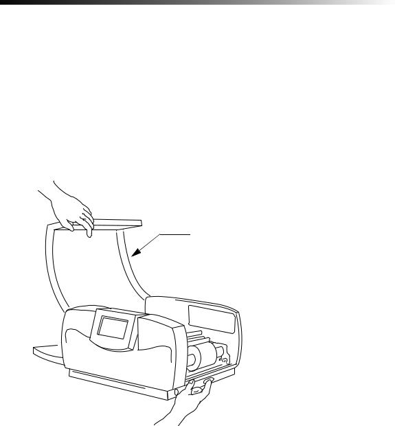
1)Remove the bag from around the printer.
2)Press the red cover release button and raise the printer cover up and away to the left.
The release button is located on the lower right side of the printer.
Printer cover
 Cover release button
3) Remove and discard the foam piece that surrounds the printhead inside the printer.
1-2 ¡ |
Setting up your system |
4)Close the printer cover by pressing down on the top right side until you hear it click into place.
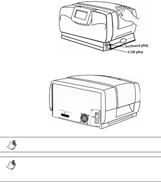
5)Plug the keyboard into the lower right side of the printer as shown above.
6)Plug the power cord into the back of the printer as shown below. Plug the other end of the cord into an AC power outlet.
on/off switch
Power plug
Note: Be sure the AC power outlet is located near the printer and is easily accessible.
Note: Users in countries outside of North America may need to supply their own power cord to meet the specifications required in individual countries. For information on power cord requirements, refer to the table on page v in this guide.
System Basics |
¡ |
1-3 |
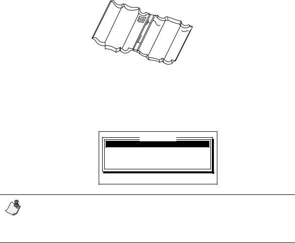
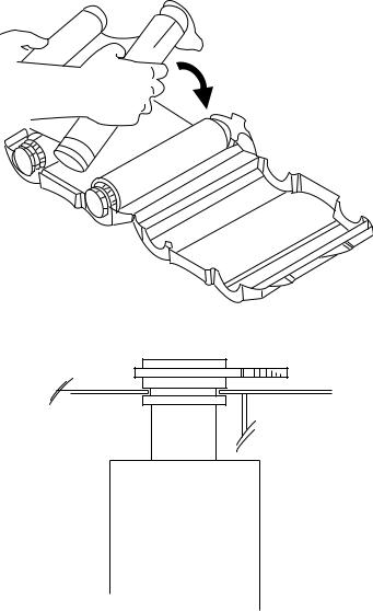
7)Locate the two sides of the clear ribbon cartridge case. Hold one side in each hand so that the interlocking pieces on each side are facing each other. Hold the sides together so that they form an upside-down V. Then fit the interlocking pieces in place and snap the sides together.
8)Follow the steps in the next two subsections in this chapter to load ribbon and tape in the printer.
9)To turn on the system’s power, push down on the left side of the power switch (the 1 position). Refer to the illustration in step 6.
When you first turn the system on, an introductory screen displays briefly and then the Application window appears. The items listed depend on which applications are available in your system.
Application
Freeform
Signs
Hazardous Waste Labels
Pipe Markers
Press ↑↓, ENTER or SETUP
Note: If supplies are not installed when you turn on the system, the “Unknown supply type” message appears. Refer to Working with supplies on page 4-1 for details on this message and how to respond to it. Also note that if the system doesn’t detect a keyboard, it assumes you want to control it from a PC, and the “On line” message displays. Refer to Chapter 6, “Using the Printer With a PC,” for details.
Refer to Using the display screen on page 1-13 for details on using the windows and for other introductory information about the system. Then refer to the remaining chapters in this guide for details on creating labels and making them look just the way you want!
1-4 ¡ |
Setting up your system |
Inserting and removing tape
This section describes how to insert and remove the system’s supply tape. These directions assume that you are facing the front of the printer (where the display screen is located).
Note: When you open the printer, you’ll see a set of illustrations attached to the inside of the unit. These illustrations show you how to install the tape (on the right side of the printer) and the ribbon (on the left side). Illustrations five through seven refer to tape loading.
1)Press the red cover release button and raise the printer cover up and away to the left.
The release button is located on the lower right side of the printer, as shown on page 1-2.
2)If a roll of tape is already installed, remove it.
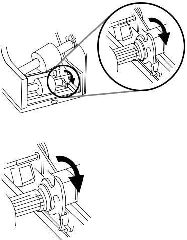
•Flip the blue memory cell flag counter-clockwise out of the red memory cell holder.
•Rotate the tape roll clockwise until the leading edge of the tape is removed from the tape feed slot and starts to rewind around the tape roll.
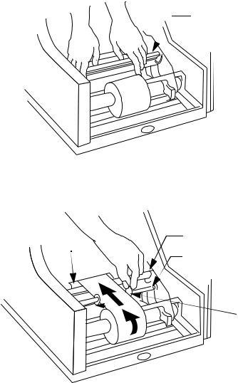
•Grasp the tape spool and pull it toward you, compressing the spring on the near side of the printer. When the gray tape roll insert is no longer covering the blue drive cone, lift the tape spool out of the printer.
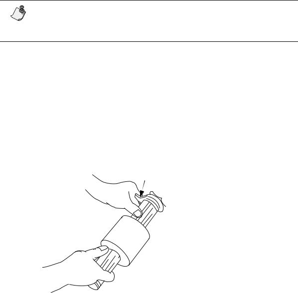
3)If you are inserting a new roll of tape, remove the shrinkwrap from it and pull off the yellow tab. Hold the tape spool you are inserting so that the blue memory cell flag is on
the far side of the roll.
Blue memory cell flag
 Tape spool
System Basics |
¡ |
1-5 |
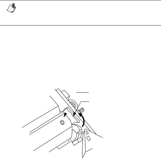
4)Place the near end of the gray tape roll insert over the blue drive cone in the lower right side of the machine. Pull the tape spool toward you, then place the opposite end of the gray tape roll insert over the blue drive cone on that side.
5)Flip the blue memory cell flag clockwise so that it is seated in the red memory cell holder.
1-6 ¡ |
Setting up your system |
6)Lift and remove the tape wiper from the printer.
If you need to replace the wiper pad, see Cleaning the system on page 7-1.
Tape wiper
7)Grasp the leading edge of the tape and guide it over the metal bar and black roller and into the red tape feed slot. (Note that you may need to first slide the two red tape guides out of the way.)
A set of arrows marks the tape feed slot. Feed the tape in below those arrows.
Black roller
Tape feed slot
Metal bar
 Tape guides
8)Slide the two red tape guides towards the tape so they snap into place along each side of the tape, as shown above.
9)Replace the tape wiper.
10)Close the printer cover by pressing down on the top right side until you hear it click into place.
System Basics |
¡ |
1-7 |
Inserting and removing ribbon
This section describes how to insert and remove the system’s supply ribbon. These directions assume that you are facing the front of the printer (where the display screen is located).
Note: When you open the printer, you’ll see a set of illustrations attached to the inside of the unit. These illustrations show you how to install the tape (on the right side of the printer) and the ribbon (on the left side). Illustrations 1-4 refer to ribbon loading.
1)If this is the first time you have used the printer, unpack the clear plastic ribbon cartridge case, and remove the wrapping.
2)Press the red cover release button on the printer, and raise the printer cover up and away to the left.
The release button is located on the lower right side of the printer, as shown on page 1-2.
3)If a ribbon is already installed, remove the ribbon cartridge case from the printer.
•Locate the clear ribbon cartridge case in the upper left side of the printer.
•Flip the blue memory cell flag counter-clockwise out of the red memory cell holder.
•Snap the hook on the memory cell flag to the ribbon cartridge case.
Ribbon cartridge case
Memory cell flag
1-8 ¡ |
Setting up your system |
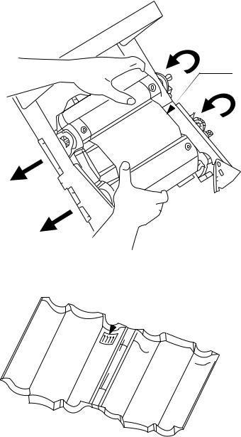
•Grasp both sides of the ribbon cartridge case and pull it toward you, compressing the spring on the near side of the printer. When the far side of the gray ribbon roll inserts no longer cover the blue drive cones, lift the ribbon cartridge case out of the printer.
Ribbon wiper is located here beneath the ribbon cartridge.
4)Set the ribbon cartridge case on a flat surface and open the case. If the case contains a ribbon, lift it out of the case. Place the case so that the white “Flag here” label is on the far side of the case.
 “Flag here” label
System Basics |
¡ |
1-9 |
5)If you’re inserting a new ribbon, remove and discard the shrinkwrap.
6)Hold the ribbon cartridge you are inserting so that the blue memory cell flag is on the far right side of the cartridge. Place the ribbon cartridge into the ribbon cartridge case, ensuring that the memory cell flag is in the opening indicated by the label.
7)Place the second groove on the ribbon cartridge insert into the edges of the ribbon cartridge case.
1-10 ¡ |
Setting up your system |
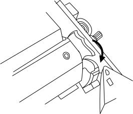
8)Close the ribbon cartridge case as shown below. Hook the blue memory cell flag onto the ribbon cartridge case.
9)Place the near end of the gray ribbon roll inserts over each of the blue drive cones in the upper left side of the printer. Grasp both sides of the case and pull it toward you so that the spring compresses, then place the opposite ends of the gray ribbon inserts over the blue drive cones on that side.
System Basics |
¡ 1-11 |
10)Flip the blue memory cell flag clockwise so that it is seated in the red memory cell holder.
11)Close the printer cover by pressing down on the top right side until you hear it click into place.
1-12 ¡ |
Setting up your system |
Using the display screen
After your system has started, the display screen lists choices similar to the ones shown below. You can choose to run a specialty application, such as Signs, which guides you through the steps of creating certain kinds of safety and warning signs. You can also choose to create a freeform label, which gives you complete control over setting up labels and selecting options. Chapter 2 discusses each of these label creation methods.
Note: When the Application window is displayed, you can press the Setup key on the labeling system keyboard to choose settings before selecting an application. Refer to Setting system defaults on page 1-26.
Application
Freeform
Signs
Hazardous Waste Labels
Pipe Markers
Press ↑↓, ENTER or SETUP
System Basics |
¡ 1-13 |
If you select the Freeform option in the Application window (by moving the cursor to that option and pressing Enter), the display screen functions as described in this section. If you choose one of the specialty applications, the display screen is used a little differently. Refer to Using standard layouts on page 2-11 and to the sections describing the specialty applications located at the end of this guide.
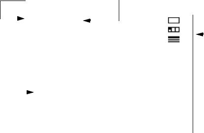
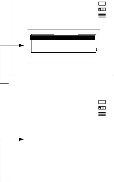
The screen on your system displays several types of information as shown in the following illustrations and discussed in the following subsections.
Text entry area: Displays text and |
|
Cursor: Blinking character that shows |
other label elements as you type. |
|
current position in the display. |
|
|
|
|
High Pressure Steam= |
|
|
: |
|
1 |
|
|
|
|
|
|
|
|
||||||||
|
|
|
|
|
|
|||||||
|
|
|
|
|
|
|
|
: |
|
1 |
|
|
|
|
|
|
|
|
|
|
: |
|
1 |
|
|
|
|
|
|
|
|
|
|
|
1 |
|
|
|
|
|
|
|
|
|
|
|
|
|
|
|
|
|
|
|
|
|
|
|
|
|
|
|
|
|
|
|
|
|
|
|
|
|
|
|
Navigation area: |
||
|
|
|
|
|
|
|
|
|
|
|||
|
|
|
|
|
|
|
|
|
|
Indicates current |
||
|
|
|
|
|
|
|
|
|
|
label, area and line |
||
|
|
|
|
|
High Pressure Steam |
|
|
number. Also |
||||
|
|
|
|
|
|
|
|
|
|
displays label |
||
Preview area: |
|
|
|
|
|
|
||||||
|
|
|
|
|
|
length. |
||||||
Shows what the |
|
|
|
|
|
|
||||||
|
|
|
|
|
|
|
|
|
||||
label will look |
|
|
|
|
|
|
|
|
|
|||
like when |
|
|
|
|
|
|
|
|
|
|||
|
|
|
|
|
|
|
|
|
||||
printed. |
|
|
|
|
|
|
|
|
|
|||
|
|
|
|
|
|
|
|
|
|
|
|
|
1-14 ¡ |
Using the display screen |
|
|
|
|
High Pressure Steam= |
: |
1 |
|
|
: |
1 |
|
|
|
|
|
|
: |
1 |
|
|
|
1 |
|
|
|
|
|
Type Options |
|
Color: |
**Black* |
Expand/Condense: |
100% |
Italics: |
Off |
Underline: |
Off |
Press ↑↓←→, ENTER or ESCAPE |
|
A |
|
a |
|
Selection window: Displays options you can set and choices you can make.
|
|
|
|
High Pressure Steam= |
: |
|
1 |
|||
|
|
|
|
|
: |
|
1 |
|||
|
|
|
|
|
: |
|
1 |
|||
|
|
|
|
|
|
|
|
1 |
|
|
|
|
|
|
|
|
|
|
|
|
|
|
|
|
|
|
|
|
|
|
|
|
|
|
|
|
Printing paused. |
|
|
|
|
|
|
|
|
|
|
Press Enter to continue or Escape |
|
|
|
|
|
|
|
|
|
|
|
|
|
|
|||
|
|
|
|
to quit. |
|
|
|
|
|
|
|
|
|
|
|
|
|
|
|
|
|
|
|
|
|
|
|
|
|
|
|
|
|
|
|
|
|
|
|
|
|
|
|
Message window: Displays information or instructions about something you need to do.
System Basics |
¡ 1-15 |

The text entry area
As you create labels, the information you enter (such as text and formatting markers) displays in the text entry area. If you type more characters on a line than will fit in the display window, the display scrolls so the new characters are visible. Press the Enter key to begin a new line on the label. Use the up and down (↑ and ↓) and left and right (← and →) arrow keys on the keyboard to move the cursor around the text entry area within a label.
As you work on a label, the information is stored in the system’s temporary memory which is called the text buffer. The text buffer stores everything you enter until you delete or clear it or turn the system off. As previously noted, all information in the text buffer isn’t visible at once. If you have created several labels or areas using the New Label and New Area keys, only one label or area is visible at a time. Use the Next/Prev Label and Next/Prev Area keys to move between labels and areas.
The navigation area
The navigation area indicates the number of the label, area and line you are currently working in. It also displays the current label length and provides a way to quickly move to other labels, areas and lines. Note that the navigation area is used for moving between labels, areas and lines that already exist. To create new items, you need to use the New Label, New Area and Enter keys.
•To move to a specific label, area or line, press the Tab key to move the cursor from the text entry area to the navigation area. Use the up and down arrow keys (↑ and ↓) to move to the label, area or line field. Type the number of the item you want to move to (for example, enter 5 in the label field) and press Enter. The cursor moves to the specified line, area or label. (You can press Tab again to return the cursor to the text entry area without moving to a different label, area or line.)
•If the area or line you chose to move to does not exist, the cursor moves to the first line or area in the specified label. If the requested label does not exist, the following message displays:
Label does not exist
The cursor returns to the navigation area, and you can press Escape to return the cursor to the text entry area.
1-16 ¡ |
Using the display screen |
•The bottom line in the navigation area shows the length of the current label. If you haven’t specified a label length (see Setting label length on page 3-13), this value indicates the length of the data you have entered for the current label. This length includes the leader and trailer, which are the blank tape at the beginning and end of a label. If you have specified a label length, that value is displayed.
The label length indicator uses the unit of measure selected for the Length Units option. See Setting system defaults on page 1-26 for more information.
The preview area
The preview area is designed to give you an idea of what a label will look like when it’s printed. Unless you turn Off the Automatic Preview setting in Setup, the system automatically displays the text and symbols you’ve entered and applies any formatting changes you’ve made, bar codes you’ve inserted, date and time information you’ve entered, and so on. Note that the preview area does not show any colors that you’ve selected. Refer to Setting system defaults on page 1-26 for more information about the Automatic preview setting.
System Basics |
¡ 1-17 |
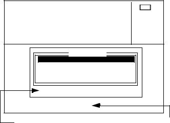
The selection window
The selection window lets you choose options that you want to set and select settings for those options. When you press a function key on the labeling system keyboard, a selection window with the same name as the key you pressed displays in the preview area. For example, when you press the Type Options key, you need to select settings for the options. The window shown below appears when you press the Type Options key.
High Pressure Steam |
: 1 |
 : 1
: 1  : 1
: 1
13.75”
|
Type Options |
Color: |
**Black* |
Expand/Condense:100% |
|
Italics:Off |
|
Underline:Off |
|
|
Press ↑↓←→, ENTER or ESC |
|
Aa |
The help line below the |
In some cases, the sample area |
selection window displays the |
shows you the effect of the setting |
keys that are available. |
that’s currently selected. |
In most selection windows, you can use the following keys.
•Press the up and down arrow keys (↑ and ↓) to move the cursor between the options displayed in the window. If an arrow appears on the right side of the window, the window contains options that don’t fit in the display. Press the arrow keys to display the additional options.
•When an option is highlighted, press the left and right arrow keys (← and →) to display the choices you can select. Some options, such as underlining, have on/off options. For other options, such as Justification, you can select from several choices. Continue to press the keys to scroll through the available choices. The setting that is displayed when you close the window is the one that will be used.
•Use the alphanumeric keys on the keyboard to type your choice when an option requires it. For example, if you are changing the type size, you need to type the size you want to use.
•Press the Enter key to accept any changes you’ve made in the selection window. The system then either returns you to the text entry area and redisplays the preview area or carries out the function you chose. In some cases, additional windows or prompts may appear.
•Press the Escape key to return to the text entry area without accepting any changes you’ve made in the selection window.
1-18 ¡ |
Using the display screen |

Markers
The symbols illustrated and described in the following table are called markers. They appear in the text entry area to show where you have changed the look of a label or inserted a special feature such as a sequence or a bar code. When you print a label, the markers do not print but the information in the marker is used to determine how the label should be printed.
Marker |
What it represents |
|
|
Change marker |
Displays when you use the Type Options key or if you select a type style |
|
or type size for a certain section of text. All text following the marker |
|
uses the setting that was selected at the marker until the setting is |
|
changed again. The system inserts a change marker each time you |
|
make a type change; you could have several markers in a row if you |
|
make multiple changes. (If you make multiple changes in a window at |
|
one time, such as in the Type Options window, all changes are stored in |
|
the same change marker.) If you prefer to have fewer change markers, |
|
make your first type change, place the cursor on that change marker and |
|
make your other changes. This stores the changes in one marker. |
|
|
Sequence marker |
Appears if you have pressed the Sequence key to set up a series of |
|
labels. Refer to Creating sequences on page 3-28. |
|
|
Symbol marker |
Appears when you have placed a special symbol within the text by |
|
pressing the Graphics key and entering a symbol number. Refer to Add- |
|
ing graphics on page 3-11. |
|
|
Date/time marker |
Indicates that the time and/or date will be printed at that point on the |
|
label. See Using the date and time option on page 3-24. |
|
|
Bar code marker |
Appears when you press the Bar Code key. All information between the |
|
two bar code markers is considered to be part of the bar code. Refer to |
|
Working with bar codes on page 3-30. |
Special bar code characAppears when you hold down the Alt key and press Bar Code while ter marker entering certain bar code symbologies. Refer to Working with bar
codes on page 3-30.
System Basics |
¡ 1-19 |
The text buffer can contain up to 64 type changes made with change markers (such as fonts, type sizes and underlining). If you exceed this number, the following message displays. You’ll need to delete an existing type change before you can add another one.
Too many type changes
System messages
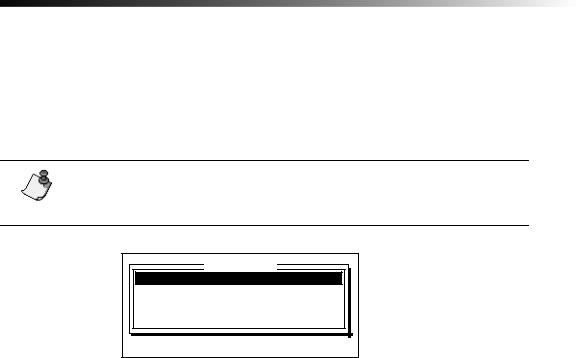
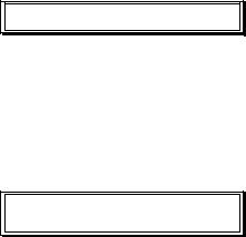
System messages may display in the preview area to give information about something you have done, ask you to confirm an action (such as deleting a file) or tell you what you’ve done wrong if you’ve made an error. Many of these messages disappear from the screen automatically, although some ask you to press a key to continue.
Ribbon out. Reload ribbon. Press any key to continue.
Some messages require you to respond to a question, as shown below. If a yes/no response is required, you can press Enter to accept the displayed response, press the ← or → key to display Yes or No and then press Enter, or type the first letter of the word.
|
Are you sure? |
No |
|
|
|
|
|
|
|
|
|
1-20 ¡ |
Using the display screen |
 Loading...