


 Loading...
Transfer Printer BP-PR PLUS series
Quick Operator’s Guide
Edition 7/06

BP-PR PLUS series
Information on the scope of delivery, appearance, performance, dimensions and weight reflect our knowledge at the time of printing. We reserve the right to make modifications.
All rights, including those regarding the translation, are reserved.
Approval
The transfer printers comply with the following safety guidelines: CE EC Low-Voltage Directive (73/23/EEC)
EC Machine Directive (98/37/EC)
EC Electromagnetic Compatibility Directive (89/336/EEC)
FCC Conditions from Part 15 of the FCC Regulations for Class A computing devices.
Operation of this device may cause radio or television interference under unfavorable conditions, which would need to be remedied by the operator using countermeasures.
W.H. Brady |
Identification Solutions Division |
Lindestraat 21 |
6555 W. Good Hope Road |
Industriepark C3 |
PO Box 2131 |
9240 Zele Belgium |
Milwaukee, WI 53201 U.S.A. |
Tel.: +32 52 457 811 |
Phone: 1-800-537-8791 Fax: 1-800-292-2289 |
e-mail: support@brady.be |
|
2 |
Quick Operator’s Guide |
Edition 7/06 |

BP-PR PLUS series
Notes on the documentation
1 Notes on the documentation
The documentation for the BP-PR PLUS series transfer printers is comprised of the following parts:
•Operating Instructions
•Configuration Instructions
•Service Instructions
Additional documentation
•Spare parts lists
•Programming manual
2 Safety and the environment
Read these operating instructions carefully before using the transfer printer for the first time. The operating instructions describe all of the functions of the transfer printer during operation. The available functions depend on the version used for a specific job.
A detailed product description with all the technical data can be found in the “Configuration Instructions for the BP-PR PLUS series“.
2.1Intended use
•The transfer printer is a state-of-the-art device which complies with the recognized safety-related rules and regulations. Despite this, a danger to life and limb of the user or third parties could arise and the transfer printer or other property could be damaged while operating the device.
•The transfer printer may only be used while in proper working order and for the intended purpose. Users must be safe, aware of potential dangers and must comply with the operating instructions! Faults, in particular those which affect safety, must be remedied immediately.
•The transfer printer is solely intended to print suitable media which have been approved by the manufacturer. Any other or additional use is not intended. The manufacturer/supplier is not liable for damage resulting from misuse. Any misuse is at your own risk.
•Intended use includes heeding the operating instructions, including the maintenance recommendations/regulations specified by the manufacturer.
Edition 7/06 |
Quick Operator’s Guide |
3 |

BP-PR PLUS series
Safety and the environment
2.2Safety notes
•The transfer printer is designed for power supply systems from 100 V AC to 240 V AC. Connect the transfer printer only to electrical outlets with a ground contact.
•Couple the transfer printer to devices using extra low voltage only.
•Before making or undoing connections, switch off all devices involved (computer, printer, accessories etc.).
•Operate the transfer printer in a dry environment only and do not get it wet (sprayed water, mist etc.).
•If the transfer printer is operated with the cover open, ensure that clothing, hair, jewelry and similar personal items do not contact the exposed rotating parts.
•The print mechanism can become hot during printing. Do not touch it during operation and allow it to cool down before changing the media or before removal or adjustment.
•Carry out only the actions described in these operating instructions. Other tasks may only be performed by trained personnel or service technicians.
DANGER!
Risk of death via mains voltage!
Do not open the housing of the transfer printer.
2.3Environmentally-friendly disposal
Used devices contain valuable recyclable materials which should be utilized.
Dispose of used devices separately from other waste, i.e. via an appropriate collection site.
The modular nature of the transfer printer allows it to easily be disassembled into its component parts so that the parts can be turned in for recycling.
The PCB of the transfer printer has a lithium battery.
Dispose of this battery in a collection container for old batteries at the store or with the public waste disposal authority.
4 |
Quick Operator’s Guide |
Edition 7/06 |
BP-PR PLUS series
Installation
3 Installation
3.1Unpacking the transfer printer
Lift the transfer printer out of the box via the straps.
Check transfer printer for damage which may have occurred during transport.
Check delivery for completeness.
Scope of delivery
•Transfer printer
•Empty cardboard core, mounted on ribbon take-up hub
•Tear-off plate (basic devices only)
•Dispense plate (peel-off device version only)
•Power cable
•Documentation
 Retain the original packaging for subsequent transport.
3.2Setting up the transfer printer
CAUTION!
The device and the print media can be damaged by moisture and water.
The transfer printer may only be set up in a dry place protected from sprayed water.
Set up printer on a level surface.
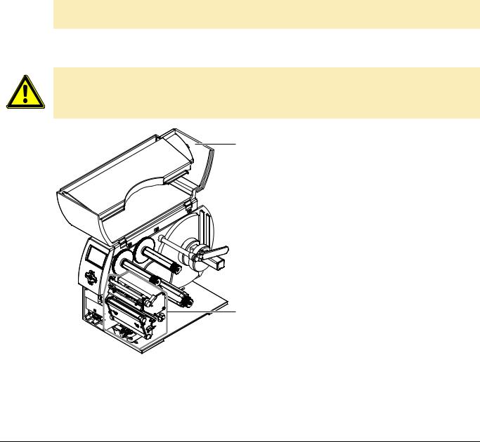
1Open cover (1) of the transfer printer.
Remove foam transportation safeguards near the printhead (2).
2
Fig. 1: Removing the transportation safeguards
Edition 7/06 |
Quick Operator’s Guide |
5 |
BP-PR PLUS series
Installation
3.3Connecting the transfer printer
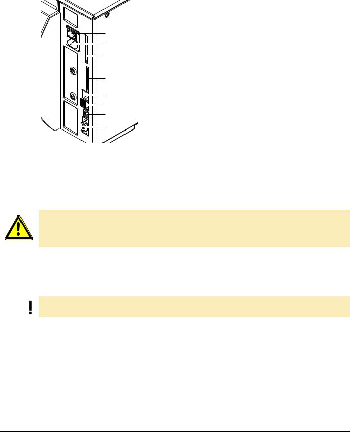
|
1 |
Power switch |
|
2 |
Power connection jack |
1 |
3 |
Slot for Cardbus or a Type II PC card |
4 |
Slot for a CompactFlash memory card |
|
2 |
5 |
Ethernet 10/100 Base-T |
3 |
6 |
USB port for a keyboard or scanner |
7 |
USB high-speed slave port |
|
|
8 |
Serial RS 232 C port |
4 |
|
|
5
6
7
8
Fig. 2: Power and computer connections
3.3.1Connecting to the power supply
The printer is equipped with a versatile power supply unit. The device may be operated with a mains voltage of 230 V AC/ 50 Hz or 115 V AC/60 Hz without any adjustments or modifications.
CAUTION!
The device can be damaged by undefined switch-on currents.
Set the power switch (1) to "O" before plugging in the device.
1.Insert power cable into power connection jack (2).
2.Insert plug of the power cable into a grounded electrical outlet.
3.3.2Connecting to a computer or computer network
Insufficient or missing grounding can cause faults during operation.
Ensure that all computers and connection cables connected to the transfer printer are grounded.
Connect transfer printer to computer or network with a suitable cable.
Details on the configuration of the individual interfaces are found in the “Configuration Instructions“.
3.4Switching the transfer printer on and off
Once all connections have been made:
Switch printer on via the power switch (1).
The printer runs through a system test and then indicates the system status Ready in the display. If an error has occurred while the system was starting up, the  symbol and the error type are displayed.
6 |
Quick Operator’s Guide |
Edition 7/06 |

BP-PR PLUS series
Operating panel
4 Operating panel
4.1Layout of the operating panel
1
2
The operating panel is comprised of the graphical display (1) and the navigator pad (2) with five integrated buttons.
The graphical display informs you of the current status of the printer and the print job, reports errors and shows the printer settings in the menu.
The button functions are dependent on the current printer status:
Active functions are indicated by the illuminated letters and symbols on the buttons of the navigator pad.
While printing, active functions illuminate white (e.g. menu or feed) Active functions are illuminated in orange in the offline menu (arrows, button)
Fig. 3: Operating panel
4.2Functions of the operating panel during printing
4.2.1Symbol indicators
The symbol indicators shown in the following table can appear on the status line of the screen, depending on the configuration of the printer. They inform you of the current status of the printer at a glance. For configuration of the status line, see the “Configuration Instructions“.
Symbol |
Meaning |
Symbol |
Meaning |
|
|
|
|
|
Time |
|
Printhead temperature |
|
|
|
|
|
Date |
|
PPP credit |
|
|
|
|
|
Ribbon supply status |
|
User memory |
|
|
|
|
|
WLAN field strength |
|
Input buffer |
|
|
|
|
|
Ethernet status |
|
Printer receiving data |
|
|
|
|
Tab. 1: Indicator symbols during printing
Edition 7/06 |
Quick Operator’s Guide |
7 |
Loading...