


CONTENTS |
|
Safety Information............................................................................................................................. |
2 |
Warranty ............................................................................................................................................. |
2 |
Product Description .......................................................................................................................... |
3 |
Accessories ....................................................................................................................................... |
3 |
Specifications ................................................................................................................................ |
4-7 |
Electrostatic Discharge Sensitive (ESDS) Device Handling ......................................................... |
8 |
Part List Notes ................................................................................................................................... |
8 |
Frequently Ordered Items ................................................................................................................ |
9 |
Packaging Part List, 3•2•1 Series II Home Entertainment System (see Figure 1) ..................... |
10 |
Figure 1. 3•2•1 Series II Home Entertainment System Packaging View .......................................... |
11 |
Packaging Part List, 3•2•1 Series II Accessory Kit (see Figure 2) .............................................. |
12 |
Figure 2. Accessory Kit Exploded View ............................................................................................. |
12 |
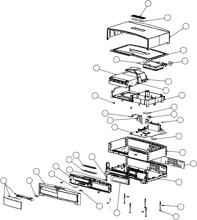
Main Part List, 3•2•1 Series II Console Assembly (see Figure 3) ................................................ |
13 |
Figure 3. 3•2•1 Series II Console Exploded View ............................................................................. |
14 |
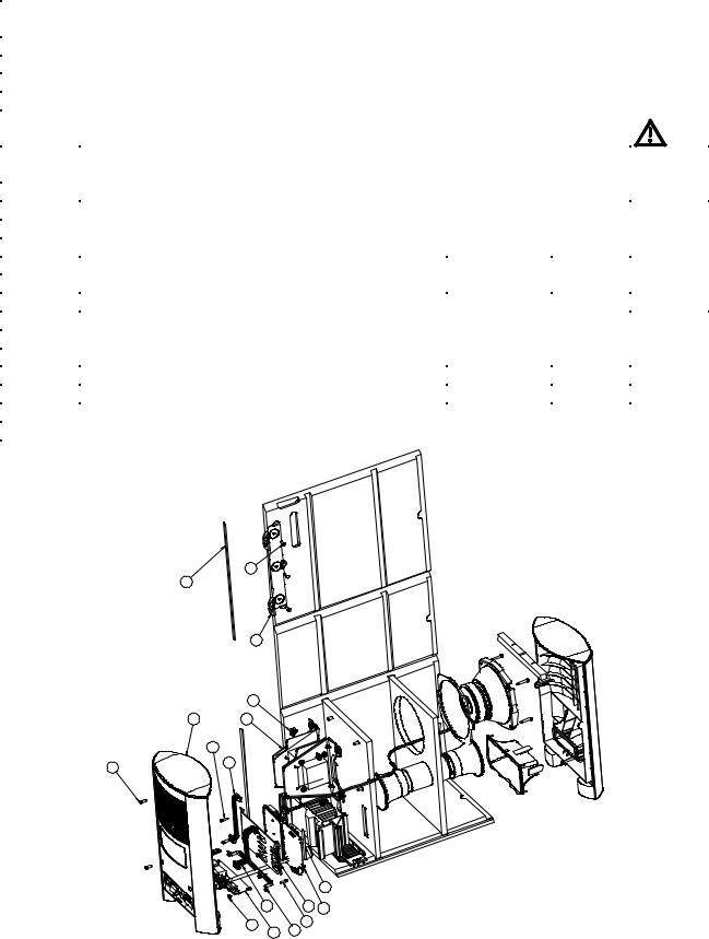
Main Part List, Bass Module (see Figure 4) .................................................................................. |
15 |
Figure 4. Bass Module Packaging View ........................................................................................... |
15 |
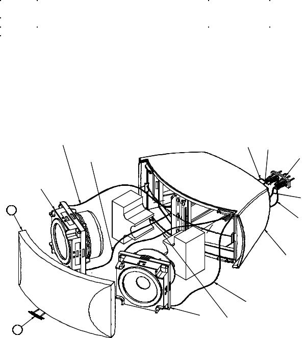
Main Part List, Standard 3•2•1 Array Assembly (see Figure 5) ................................................... |
16 |
Figure 5. Standard 3•2•1 Array Assembly Exploded View ................................................................ |
16 |
Main Part List, 3•2•1 GS Array Assembly (see Figure 6) ............................................................. |
17 |
Figure 6. 3•2•1 GS Array Assembly Exploded View .......................................................................... |
17 |
Electrical Part Lists ................................................................................................................... |
18-41 |
Console Main PCB Assembly .................................................................................................. |
18-29 |
Console Tuner PCB Assembly ................................................................................................. |
30-33 |
Bass Module DSP/Amplifier PCB Assembly ........................................................................... |
34-40 |
Bass Module Input/Output PCB Assembly ................................................................................... |
41 |
Disassembly Procedures ......................................................................................................... |
42-47 |
Console Procedures ................................................................................................................. |
42-45 |
Bass Module Procedures ......................................................................................................... |
45-46 |
Standard Satellite Array Procedures ............................................................................................. |
47 |
GemstoneTM Satellite Array Procedures ........................................................................................ |
47 |
Test Procedures ........................................................................................................................ |
48-52 |
Figure 7. Console Main PCB Layer 1 Topside Etch Layout Diagram ............................................... |
53 |
Figure 8. Console Main PCB Layer 2 Ground Plane Layout Diagram .............................................. |
54 |
Figure 9. Console Main PCB Layer 3 Power Plane Layout Diagram ................................................ |
55 |
Figure 10. Console Main PCB Layer 4 Bottom Etch Layout Diagram .............................................. |
56 |
Figure 11. Console Tuner PCB Topside Etch Layout Diagram ......................................................... |
57 |
Figure 12. Console Tuner PCB Bottom Side Etch Layout Diagram .................................................. |
58 |
Figure 13. Bass Module DSP/Amplifier PCB Topside Etch Layout Diagram .................................... |
59 |
Figure 14. Bass Module DSP/Amplifier PCB Bottom Side Etch Layout Diagram ............................. |
60 |
Figure 15. Bass Module Input/Output PCB Topside Etch Layout Diagram ....................................... |
61 |
Figure 16. Bass Module Input/Output PCB Bottom Side Etch Layout Diagram ............................... |
61 |
Appendix .................................................................................................................................... |
62-66 |
Obtaining System Information from the Media Center Display .................................................. |
62 |
DVD Lock options ..................................................................................................................... |
63-64 |
Setting a password and restriction level ...................................................................................... |
63 |
DVD Lock Bypass ............................................................................................................................ |
64 |
321 Series II System Date of Manufacture Information ............................................................... |
64 |
Glossary of Terms ........................................................................................................................... |
65 |
Service Manual Revision History ................................................................................................... |
66 |
1

SAFETY INFORMATION
1.Parts that have special safety characteristics are identified by the  symbol on schematics or by special notes on the parts list. Use only replacement parts that have critical characteristics recommended by the manufacturer.
2.Make leakage current or resistance measurements to determine that exposed parts are acceptably insulated from the supply circuit before returning the unit to the customer.
Use the following checks to perform these measurements:
A.Leakage Current Hot Check-With the unit completely reassembled, plug the AC line cord directly into a 120V AC outlet. (Do not use an isolation transformer during this test.) Use a leakage current tester or a metering system that complies with American National Standards Institute (ANSI) C101.1 "Leakage Current for Appliances" and Underwriters Laboratories (UL) UL6500 / UL60065 / IEC 60065 paragraph 9.1.1. With the unit AC switch first in the ON position and then in OFF position, measure from a known earth ground (metal waterpipe, conduit, etc.) to all exposed metal parts of the unit (antennas, handle bracket, metal cabinet, screwheads, metallic overlays, control shafts, etc.), especially any exposed metal parts that offer an electrical return path to the chassis. Any current measured must not exceed 0.5 milliamp. Reverse the unit power cord plug in the outlet and repeat test. ANY MEASUREMENTS NOT WITHIN THE LIMITS SPECIFIED HEREIN INDICATE A POTENTIAL SHOCK HAZARD THAT MUST BE ELIMINATED BEFORE RETURNING THE UNIT TO THE CUSTOMER.
B.Insulation Resistance Test Cold Check-(1) Unplug the power supply and connect a jumper wire between the two prongs of the plug. (2) Turn on the power switch of the unit. (3) Measure the resistance with an ohmmeter between the jumpered AC plug and each exposed metallic cabinet part on the unit. When testing 3 wire products, the resistance measured to the product enclosure should be between 2 and infinite MOhms. Also, the resistance measured to exposed input/output connectors should be between 4 and infinite MOhms. When testing 2 wire products, the resistance measured to exposed input/output connectors should be between 4 and infinite MOhms. If it is not within the limits specified, there is the possibility of a shock hazard, and the unit must be repaired and rechecked before it is returned to the customer.
CAUTION: The Bose® 3•2•1 Series II Home Entertainment System contains no user-serviceable parts. To prevent warranty infractions, refer servicing to warranty service stations or factory service.
PROPRIETARY INFORMATION
THIS DOCUMENT CONTAINS PROPRIETARY INFORMATION OF
BOSE CORPORATION WHICH IS BEING FURNISHED ONLY FOR
THE PURPOSE OF SERVICING THE IDENTIFIED BOSE PRODUCT
BY AN AUTHORIZED BOSE SERVICE CENTER OR OWNER OF
THE BOSE PRODUCT, AND SHALL NOT BE REPRODUCED OR
USED FOR ANY OTHER PURPOSE.
WARRANTY
The Bose® 3•2•1 and 3•2•1GS Series II Home Entertainment Systems are covered by a limited 1-year transferable warranty.
2
PRODUCT DESCRIPTION
The 3•2•1 Series II Home Entertainment System is the replacement for the 3•2•1 and 3•2•1GS Series I Home Entertainment Systems. It uses the same system concept of a console with a dedicated bass module with TrueSpaceTM signal processed surround sound from 2 satellite arrays.
The console will play video DVDs, DVD-R and DVD+R discs, audio CDs, Video CDs, CD-R and CD-RWs, and MP3 CDs. MP3 disc tracks must be burned in a single closed session. The MP3 disc format must be ISO9660 and each file must have an “.mp3” extension and have no other periods in the filename.
The bass module electronics house some signal processing, power supplies and amplification for the console. The console and bass module are not compatible with the 3•2•1 Series I console and bass module. They cannot be used to replace the other Series components. The speaker arrays are the same as currently used on the 3•2•1 and 3•2•1GS systems. The system includes an enhanced universal type IR remote control similar to that used on the 3•2•1GS Series I system. The remote is non-repairable.
The 3•2•1 Series II uses standard 3•2•1 arrays with a cloth grille. The arrays are graphite in color. The 3•2•1GS Series II systems use the GemstoneTM arrays in both graphite and silver. The array cable color matches the array color. The console for both 321 and 321GS systems is graphite with a silver front bezel. The bass module is graphite, as is the IR remote control.
ACCESSORIES
The Bose 3•2•1 and 3•2•1GS Series II Home Entertainment Systems shelf speakers are compatible with Bose mounting accessories, including the UB-20 wall brackets, UFS-20 floor stands and UTS-20 table stands.
3
SPECIFICATIONS
System Specifications:
Power Rating:
US/Canada:
Europe/UK/Aus:
Japan:
Dual Voltage:
Console Inputs:
Video Outputs:
External Antennas:
Maximum Ambient Temperature:
Low Frequency Cut-off (typical):
Arrays:
Bass Module:
Woofer Impedance:
Weights:
3•2•1 Series II Packed System: 3•2•1GS Series II Packed System: Console:
Bass Module: 3•2•1 Arrays, each:
3•2•1GS Arrays, each:
IR Remote Control (batteries installed):
Dimensions:
Console: Bass Module:
Bass Module internal volume: 3•2•1 Arrays:
3•2•1GS Arrays: IR Remote:
Distortion and Noise:
Dynamic Range:
Distortion:
Output Noise:
120VAC, 60 Hz, 300W 220-240VAC, 50/60 Hz, 300W 100VAC, 50/60 Hz, 300W 115/230VAC, 50/60 Hz, 300W
VIDEO, CAB/SAT, AUX
Composite Video, S-Video, Component Video
FM, 75 Ohm F-Connector (PAL, Europe) AM Loop, 2.5 mm mono connector
45 degrees C
3•2•1 Array Cube: 180 Hz
3•2•1GS Array Cube: 212 Hz
45 Hz
1.5 Ohms nominal DC resistance single woofer
47.9lb (21.7 kg)
44.1lb (20.0 kg)
6.8lb (3.08 kg)
24.9lb (11.77 kg)
3.0lb (1.40 kg)
1.1lb (0.50 kg)
0.44lb (0.20 kg)
13.8x 10.0 x 3.2 inches (34.9 x 25.3 x 8.2 cm) 14 x 7.5 x 20.1 inches (35.6 x 18.4 x 51.1 cm) 1205 cubic inches (19.7 liters)
7.9x 5.3 x 3.4 inches (200 x 134 x 86 mm)
5.6x 2.6 x 4.2 inches (142 x 65 x 106 mm)
9.0x 2.6 x 1.2 inches (229.6 x 64.8 x 31.2 mm)
-78 dB THD+N, unweighted, 22-22 kHz for a 1 kHz signal at -1 dB -90 dB THD+N,
unweighted, 22-22 kHz for a 1 kHz signal at -10 dB
-90 dB THD+N, unweighted,
22-22 kHz for a 1 kHz signal at -60 dB
<0.1% @ 0.5 W
<400 mVrms, A-weighted
4
SPECIFICATIONS
System Specifications (continued): |
|
Noise when Muted: |
< 400 uVrms, A-weighted |
DC Offset: |
< 50 mVdc, all channels |
Channel Balance: |
+/- 1.5 dB for all volume settings |
Channel Separation: |
> 40 dB @ 1 kHz, > 30 dB @ 10 kHz, stereo mode |
Console Specifications: |
|
Compression Formats Supported for discs |
|
inserted into the DVD/CD drive: |
AC-3, MP3, DTS, MPEG-1 (VCD), MPEG-2 |
Compression Formats NOT Supported for |
|
discs inserted into the DVD/CD drive: |
SACD Format (Sony), MLP |
Digital Formats Supported for sources |
|
connected to the digital inputs: |
AC-3, DTS, AAC (Japan only), PCM |
Analog Input Characteristics: |
|
Maximum source signal for ADC full scale: Minimum source signal for ADC full scale:
Input Impedance:
Input Coupling:
Output level from FM (mono, 75 kHz dev): Output level from AM (30% mod, 100 dBuV):
Source Impedance at 1 kHz:
Output Coupling:
S/PDIF Coaxial Input Characteristics: Sampling Rates Accommodated: Number of bits recognized:
Input Impedance:
Error Checking and Handling:
Input Coupling:
2 Vrms
200 mVrms
100k Ohms nominal +/- 10%
AC coupled to remove source DC offset
0.3 Vrms nominal
0.2 Vrms nominal
1560 Ohms nominal, +/- 10%
AC
38 kHz, 44.1 kHz, 48 kHz 16, 20 and 24
75 Ohms +/- 10%
Implements full error checking and handling, considering CRC, validity bit, loss of lock, parity error, and bi-phase error.
AC
5
SPECIFICATIONS
Console Specifications (continued):
Optical S/PDIF Input Characteristics:
Sampling Rates Accommodated: Number of bits recognized: Error Checking and Handling:
Input Connector:
Volume Control:
Film EQ:
Tone Controls:
Treble Control:
Bass Control:
FM Tuner Performance (per IHF-T-200):
Channel Spacing:
Euro/UK/Aus:
Japan:
Band Limits:
US/Can/Dual Voltage:
Euro/UK/Aus:
Japan:
De-emphasis:
US/Can/Dual Voltage:
Euro/UK/Aus/Japan:
Mono Sensitivity (30dB (S+N+D)/(N+D):
US/Can/Dual Voltage:
Euro/UK/Aus/Japan:
Euro/UK/Aus:
Japan:
50 dB Stereo Quieting Sensitivity:
US/Can/Dual Voltage (98 MHz):
Euro/UK/Aus (98 MHz):
Japan (83 MHz):
Signal to Noise Ratio @ 65 dBf: Harmonic Distortion @ 65 dBf: Capture Ratio @ 45 dBf:
AM Rejection @ 45 dBf:
38 kHz, 44.1 kHz and 48 kHz 16, 20 and 24
Implements full error checking and handling, considering CRC, validity bit, loss of lock, parity error, and bi-phase error.
TOSLINK
0 dB to full attenuation in 100 steps (100 - 0 indicated). 0 volume causes the amplifiers to mute.
Selectable on or off
Range of -12 to +12 dB in 11 steps
Range of -12 to +12 dB in 18 steps
US/Can/Dual Voltage: 200 kHz 50 kHz
100 kHz
87.7MHz - 107.9 MHz
87.50MHz - 108.00 MHz
76.00MHz - 90.00 MHz
75 usec
50 usec
(98 MHz) 15dBf nom/17.5 dBf limit
20 dBf nom / 25 dBf limit
(98 MHz) 16.0 dBf nom / 18.5 dBf limit
(83 MHz) 15.0 dBf nom / 17.5 dBf limit
38 dBf nom / 41.5 dBf limit
39.0 dBf nom / 42.5 dBf limit
38 dBf nom / 41.5 dBf limit
74 nom / limit 69 dB mono, 70 nom / limit 65 dB stereo
Mono 0.3% / limit 0.6%, stereo 0.4% / limit 0.8%
2.0 dB nominal / limit 3.0 dB
60 dB nominal / 50 dB limit
6
SPECIFICATIONS
Console Specifications (continued):
Adjacent Chan Selectivity (200 kHz):
Alternate Chan Selectivity (400 kHz):
US/Can/Dual/Japan:
Euro/UK/Aus:
Image Rejection:
US/Can/Dual/Japan:
Euro/UK/Aus:
RF Intermodulation:
Sub-carrier Product Rejection (at speaker):
Frequency Response relative to ideal deemphasis:
Stereo Channel Separation @ 1 kHz:
Auto Stop Level (seek):
Mono/Stereo Threshold:
AM Tuner Performance (per IHF-T-100):
13 dB nominal / 10 dB limit @ 45 dBf
70 dB nom/65 dB limit @ 45 dBf
75 dB nom/70 dB limit @ 45 dBf
45 dB nominal / 40 dB limit
Meets FTZ (Fernmelde Technischer Zentralamt) requirement
65 dB nominal / 55 dB limit
55 dB nominal / 45 dB limit
30 Hz to 15 kHz +/- 1.0 dB nominal, +/- 2.0 dB limit
35 dB nominal / 25 dB limit
30 dBf +/-5
40 dBf +/-5
Channel Spacing: |
|
US/CAN/DUAL: |
10 kHz |
Euro/UK/Aus/Japan: |
9 kHz |
Band Limits: |
|
US/CAN/Dual: |
530 kHz - 1710 kHz |
Euro/UK/Aus: |
522 kHz - 1611 kHz |
Japan: |
531 kHz - 1629 kHz |
Usable Sensitivity (mono, 1080 kHz): |
48 dB nominal / 54 dB limit |
Adjacent Channel Selectivity: |
23 dB nominal / 18 dB limit |
Alternate Channel Selectivity: |
30 dB nominal / 25 dB limit |
Image Rejection: |
40 dB nominal / 35 dB limit |
Auto Stop Level: |
58 dBuV/m +/- 5 dB |
Signal to Noise Ratio: |
50 dB nominal / 45 dB limit |
Distortion ( 30% modulation): |
1.0% nominal / 1.4% limit |
Frequency Response: |
220 Hz: -3 dB nominal / -6 dB limit |
|
2.0 kHz: -3 dB nominal / -6 dB limit |
7
ELECTROSTATIC DISCHARGE SENSITIVE (ESDS)
DEVICE HANDLING
This unit contains ESDS devices. We recommend the following precautions when repairing, replacing or transporting ESDS devices:
•Perform work at an electrically grounded work station.
•Wear wrist straps that connect to the station or heel straps that connect to conductive floor mats.
•Avoid touching the leads or contacts of ESDS devices or PC boards even if properly grounded. Handle boards by the edges only.
•Transport or store ESDS devices in ESD protective bags, bins, or totes. Do not insert unprotected devices into materials such as plastic, polystyrene foam, clear plastic bags, bubble wrap or plastic trays.
PART LIST NOTES
1.This part is not normally available from Customer Service. Approval from the Field Service Manager is required before ordering.
2.The individual parts located on the PCBs are listed in the Electrical Part List.
3. This part is critical for safety purposes. Failure to use a substitute replacement with the same safety characteristics as the recommended replacement part might create shock, fire and/or other hazards.
4.This part is referenced for informational purposes only. It is not stocked as a repair part. Refer to the next higher assembly for a replacement part.
8

FREQUENTLY ORDERED ITEMS
Main Assemblies |
Part Number |
CONSOLE ASSY, DVD, 120V, GRAPHITE, REGION 1 |
270900-11119 |
ASSEMBLY, BASS MODULE, 120V, GRAPHITE |
273031-11119 |
|
|
Arrays |
Part Number |
ARRAY ASSY, 321 II, GRAPHITE |
255198-001 |
ARRAY ASSY, 321GS II, GRAPHITE |
269990-001 |
ARRAY ASSY, 321GS II, SILVER |
269990-003 |
|
|
Remote Control |
Part Number |
REMOTE, IR, 3.2.1 SERIES II |
270618-001 |
BATTERY, CARBON, AA SIZE (2 REQUIRED) |
147538 |
|
|
Accessory Kits |
Part Number |
ACCESSORY KIT W/REMOTE, 321 II US, GRAPHITE |
273041-011 |
ACCESSORY KIT W/REMOTE, 321GS II, US, GRAPHITE |
273041-111 |
ACCESSORY KIT W/REMOTE, 321GS II, US, SILVER |
273041-311 |
|
|
Cables |
Part Number |
CABLE, BASS MODULE, 13 PIN, GRAPHITE |
269997-001 |
CABLE, STANDARD ARRAY, 9 PIN, GRAPHITE |
255123-001 |
CABLE, GEMSTONETM ARRAY, 9 PIN, GRAPHITE |
269984-001 |
CABLE, GEMSTONE ARRAY, 9 PIN, SILVER |
269984-003 |
CABLE, AUDIO, DUAL RCA |
185931-01 |
CABLE, VIDEO, 6', YL |
183200 |
|
|
Antennas |
Part Number |
ANTENNA, FM DIPOLE, 75 OHM, F CONN |
148589 |
ANTENNA, ASSY, AM, CD 20 |
199824-002 |
|
|
Line Cord |
Part Number |
LINE CORD, 120V, POL, DET, GRAPHITE |
260082-001 |
|
|
Owner's Guide |
Part Number |
GUIDE, OWNERS, 3-LANG 321 II |
274559 |
|
|
Feet |
Part Number |
BUMPER, RECESSED, FOOT, .88" |
142839 |
(QTY 4 FEET PER STRIP, USED ON THE BASS MODULE) |
|
FOOT, CLEAR, .312 X 0.85 |
178321-04 |
(QTY 4 FEET PER STRIP, USED ON THE ARRAYS) |
|
|
|
Other |
Part Number |
DVD, SETUP AND DEMO, 321 II, NTSC |
277723 |
|
|
Extended Length Cables |
Part Number |
SYSTEM CABLE, 25 FOOT, GRAPHITE |
281528-001 |
ARRAY CABLE, 40 FOOT, 321 II, GRAPHITE |
262070-001 |
ARRAY CABLE, 40 FOOT, 321 II, SILVER |
262070-003 |
ARRAY CABLE, 40 FOOT, 321GS II, GRAPHITE |
282301-001 |
ARRAY CABLE, 40 FOOT, 321GS II, SILVER |
282301-003 |
9
PACKAGING PART LIST
3•2•1 Series II Home Entertainment System (see Figure 1)
Item |
Description |
Part Number |
Qty per |
Note |
Number |
|
|
System |
|
1 |
COMMITMENT LETTER |
251001 |
1 |
|
2 |
SHEET, QUICKSTART, GLOBAL |
274561 |
1 |
|
3 |
ACCESSORY KIT, 321 II US, GRAPHITE |
273041-011 |
1 |
|
|
ACCESSORY KIT, 321 II GS, US, GRAPHITE |
273041-111 |
1 |
|
|
ACCESSORY KIT, 321 II GS, US, SILVER |
273041-311 |
1 |
|
4 |
LINE CORD, 120V, POL, DET, GRAPHITE |
260082-001 |
1 |
3 |
|
|
|
|
|
5 |
BAG, POLY, 13.5 x 35 x 9.5 x 2.5 mil |
114522 |
1 |
|
6 |
PACKING, TOP, EPS, CONSOLE |
276335 |
1 |
|
7 |
CONSOLE ASSY, DVD, 120V, GRAPHITE, |
270900-11119 |
1 |
|
|
REGION 1 |
|
|
|
8 |
PACKING, TOP-BTM, EPS, BASS MODULE |
276334 |
2 |
|
9 |
PACKING, TOP-BTM, EPS, SAT |
276336 |
1 |
|
10 |
ARRAY ASSY, 321 II, GRAPHITE |
255198-001 |
2 |
|
|
ARRAY ASSY, 321 II GS, GRAPHITE |
269990-001 |
2 |
|
|
ARRAY ASSY, 321 II GS, SILVER |
269990-003 |
2 |
|
11 |
ASSEMBLY, BASS MODULE, 120V, GRAPH |
273031-11119 |
1 |
US/Can |
|
ASSEMBLY, BASS MODULE, 115/230V, |
273031-61119 |
1 |
Dual |
|
GRAPH |
|
|
Voltage |
12 |
CARTON, RSC, 321 II |
276333 |
1 |
|
|
CARTON, RSC, 321 II GS |
277060 |
1 |
|
13 |
GUIDE, OWNERS, 3-LANG 321 II |
274559 |
1 |
|
14 |
CARD, REGISTRATION |
278529-001 |
1 |
|
15 |
SHEET, SLIP, COMPONENT AUDIO |
255805 |
1 |
|
16 |
ADDRESS PAGE, BOSE |
259434 |
1 |
|
17 |
BAG, POLY, 14.38 x 9.87 x 2 mil |
103351 |
1 |
|
18 |
CARD, 3.2.1 UPDATE |
268158 |
1 |
|
19 |
DVD, SETUP AND DEMO, 321 II, NTSC |
277723 |
1 |
|
- |
ADAPTOR, 120/230V, POLARIZED |
147013 |
1 |
Dual |
|
|
|
|
Voltage |
- |
SHEET, INSTRUCTION, ADAPTOR |
147751 |
1 |
Dual |
|
|
|
|
Voltage |
10
|
1 |
2 |
|
|
3 |
|
4 |
6 |
5 |
|
|
|
7 |
9 10
8
ARRAYS (ITEM 10) |
11 |
INSIDE EPS FOAM |
8
12
13 14 15 16 17 18 19
Figure 1. 3•2•1 Series II Home Entertainment System Packaging View
11

PACKAGING PART LIST
3•2•1 Series II Home Entertainment System Accessory Kit (see Figure 2)
Item |
Description |
|
Part Number |
Note |
Number |
|
|
|
|
1 |
CARTON, DIE CUT, ACCESSORY KIT, 321 II |
|
276337 |
|
2 |
CABLE, AUDIO, DUAL RCA |
|
185931-01 |
|
3 |
ANTENNA, FM DIPOLE, 75 OHM, F CONN |
|
148589 |
|
4 |
CABLE, VIDEO, 6', YL |
|
183200 |
|
5 |
REMOTE, IR, 321 II |
|
270618-001 |
|
6 |
ANTENNA, ASSY, AM, CD 20 |
|
199824-002 |
|
7 |
BAG, POLY,3 X 3 MIL |
|
194392 |
4 |
8 |
BATTERY, CARBON, AA SIZE |
|
147538 |
|
9 |
CABLE, STANDARD ARRAY, 9 PIN, GRAPHITE |
255123-001 |
|
|
|
CABLE, GEMSTONETM ARRAY, 9 PIN, GRAPHITE |
269984-001 |
|
|
|
CABLE, GEMSTONE ARRAY, 9 PIN, SILVER |
|
269984-003 |
|
10 |
BUMPER, RECESSED, FOOT, .88" |
|
142839 |
|
11 |
FOOT, CLEAR, .312 X 0.85 |
|
178321-04 |
|
12 |
CABLE, BASS MODULE, 13 PIN, GRAPHITE |
|
269997-001 |
|
13 |
PACKING, INSERT, ACCESSORY KIT, 321 II |
|
276338 |
|
|
2 |
|
|
|
|
1 |
3 |
|
|
|
|
|
4 |
|
|
|
|
5 |
|
6 |
7 |
|
|
|
8 |
|
9 |
|
10 |
|
11 |
12
13
Figure 2. Accessory Kit Exploded View
12

MAIN PART LIST
3•2•1 Series II Console Assembly (see Figure 3)
Item |
Description |
Part Number |
Qty. |
Note |
Number |
|
|
|
|
1 |
COVER, GATE (USED TO COVER RECESSS |
270910-001 |
1 |
|
|
IN THE TOP COVER, ITEM 3 BELOW) |
|
|
|
2 |
PRESSURE SENSITIVE ADHESIVE, DIE-CUT |
276995-001 |
1 |
|
|
(USED TO SECURE ITEM 1 TO ITEM 3) |
|
|
|
3 |
COVER, CONSOLE, DVD, GRAPHITE |
270909-001 |
1 |
|
4 |
SHIELD, UPPER, COVER |
270911-001 |
1 |
|
5 |
GASKET, EMI (FM ANTENNA CONNECTOR) |
276947-001 |
1 |
|
6 |
PCB ASSY, TUNER, PROGRAMMED, US |
274257-001 |
1 |
2 |
7 |
DRIVE, DVD-ROM, 1712, XQ1B10 |
270013-002 |
1 |
|
8 |
CABLE, RIBBON, ATAPI, 40 POS, 260 MM |
270918-280 |
1 |
|
9 |
CABLE, POWER, DVD, 265 MM |
270917-265 |
1 |
|
10 |
BRACKET, DVD, GRAPHITE |
270904-001 |
1 |
|
11 |
SCREW, M3-0.5 x 8, DOME WASHER |
271671-001 |
4 |
|
12 |
HEATSINK, DSP |
270920-001 |
1 |
|
13 |
CABLE, TUNER, 13 COND, FFC |
271573-120 |
1 |
|
14 |
CABLE, BUTTON, 135 MM |
270914-135 |
1 |
|
15 |
CABLE, DISPLAY, FFC, SHIELD, 5 POS, |
270601-05110 |
1 |
|
|
110 MM |
|
|
|
16 |
GASKET, EMI (BOSE LINK CONNECTOR) |
279058-001 |
1 |
|
17 |
PCB ASSY, MAIN, PROGRAMMED, |
274256-101 |
1 |
2 |
|
STANDARD |
|
|
|
18 |
TAPE, SHIELDING |
279013-001 |
1 |
|
|
(NOT USED IN LATER UNITS) |
|
|
|
19 |
SHIELD, LOWER, BASE |
270902-001 |
1 |
|
20 |
LABEL, INPUT/OUTPUT, CONSOLE |
272176-001 |
1 |
|
21 |
BASE, CONSOLE, DVD, GRAPHITE |
270901-001 |
1 |
|
22 |
FOOT, RUBBER, 12.7 DIA. x 2.38 THICK |
260465 |
4 |
|
23 |
SCREW, # 8-11, COMBO DRIVE |
271670-036 |
6 |
|
24 |
DISPLAY, VACUUM FLUORESCENT (VFD) |
275866-001 |
1 |
|
25 |
CABLE, IR, 32 MM |
270915-032 |
1 |
|
26 |
PAD, SWITCH |
270916-001 |
1 |
|
27 |
BUTTON PCB (PART OF MAIN PCB ASSY) |
- |
1 |
|
28 |
IR RECEIVER PCB |
- |
1 |
|
|
(PART OF MAIN PCB ASSY) |
|
|
|
29 |
SCREW, TAPP, 8-11 x .625, PAN, X SQ. EN |
250817-10 |
3 |
|
30 |
BEZEL, INNER |
270905-001 |
1 |
|
31 |
PIN, EJECTOR, DVD |
271619-001 |
1 |
|
32 |
OUTER BEZEL ASSY, CONSOLE |
277514-001 |
1 |
|
33 |
NAMEPLATE, 29 MM, DIAMOND CUT |
279015-001 |
1 |
|
34 |
DVD BEZEL SUB-ASSEMBLY, CONSISTS OF: |
282440-001 |
1 |
|
|
BEZEL, DVD |
270912-001 |
|
4 |
|
SPRING, TORSION |
273650 |
|
4 |
|
LENS, DVD |
270913-001 |
|
4 |
13
1
6
7
4x 11
14
15
17
|
26 |
25 |
|
27 |
|
|
|
|
|
30 |
|
32 |
28 |
|
31 |
|
|
|
|
34 |
33 |
29 3x 
24
Figure 3. 3•2•1 Series II Console Exploded View
2
3
4
5
8
9
10
12
13
16
18
19
20
21
22 4x
23 6x
14
MAIN PART LIST
Bass Module (see Figure 4)
Item |
Description |
Part |
Qty. |
Note |
Number |
|
Number |
|
|
1 |
FOAM TAPE, .32" W |
255202 |
2 ft. |
|
2 |
SCREW, TAPP, 8-11 x .5, PAN, ASY, SQ |
250817-08 |
6 |
|
3 |
BRACKET, COVER, AMP |
255179 |
1 |
|
4 |
SCREW, MACH, SEMS, WSHR, 10-32 x 0.5 |
264824-08 |
4 |
|
5 |
TRANSFORMER, EI, 100V, 50/60HZ |
261278-102 |
1 |
3 |
|
(120V SYSTEMS) |
|
|
|
|
TRANSFORMER, EI, 115/230V, 50/60HZ, R90 |
261277-102 |
|
|
|
(DUAL VOLTAGE SYSTEMS) |
|
|
|
6 |
ENCLOSURE, REAR, GRAPHITE (120V) |
267187-301 |
1 |
|
|
ENCLOSURE, REAR, GRAPHITE (DUAL VOLT) |
278055-321 |
|
|
7 |
SCREW, 6-32 x 1/2 THREAD ROLLING |
258492-08 |
4 |
|
8 |
CABLE, INPUT / OUTPUT, DIGITAL |
275179-190 |
1 |
|
9 |
SCREW, TT, 8-32 x 0.5, PAN, XREC/SQ |
255191-08 |
4 |
|
10 |
PAD, FOAM, .25" x .75" x .06" |
278144-001 |
3 |
|
11 |
PCB ASSY, INPUT / OUTPUT (120V SYSTEMS) |
270927-001 |
1 |
2 |
|
PCB ASSY, INPUT / OUTPUT (DUAL VOLT) |
270927-006 |
|
|
12 |
CABLE, ARRAY, 10 CONDUCTOR |
271561-190 |
1 |
|
13 |
BRACKET, INPUT / OUTPUT PCB |
267182-001 |
1 |
|
14 |
SCREW, TAPP, 6-13 x .5, PANN |
172783-08 |
2 |
|
15 |
BRACKET, HEATSINK |
267183-001 |
1 |
|
16 |
PCB ASSY, DSP, PROGRAMMED |
274824-001 |
1 |
2 |
17 |
PAD, THERMAL, DIODE |
267968-075 |
1 |
|
6x 2
1
2x 3
4
6 |
5 |
7 4x
8
9 4x
|
|
17 |
12 |
15 |
16 |
|
|
|
3x 10 |
14 2x |
|
13 |
|
|
11 |
|
|
Figure 4. Bass Module Exploded View
15
MAIN PART LIST
Standard 3•2•1 Array Assembly (see Figure 5)
Item |
Description |
Part Number |
Qty per |
Note |
Number |
|
|
Array |
|
1 |
GRILLE, ARRAY, GRAPHITE |
255196-001 |
1 |
|
2 |
NAMEPLATE, BOSE® LOGO |
255177-001 |
1 |
|
Note: Only the parts listed above are replaceable.
RED |
RED |
BLACK |
|
|
|
|
|
REAR PANEL |
|
BLACK |
TERMINAL STRIP |
|
|
TWIDDLERTM
DRIVER
BLACK
 1
1
RED
ARRAY
ENCLOSURE
RED
TWIDDLER
DRIVER BLACK
2
Figure 5. Standard 3•2•1 Array Assembly Exploded View
16

MAIN PART LIST
3•2•1 GS Array Assembly (see Figure 6)
Item |
Description |
Part Number |
Qty per |
Note |
Number |
|
|
Array |
|
1 |
TWIDDLER DRIVER ASSY, 50MM |
273244-001 |
2 |
|
2 |
GRILLE, METAL, ARRAY, GRAPHITE |
273748-001 |
1 |
|
|
GRILLE, METAL, ARRAY, SILVER |
273748-003 |
|
|
3 |
NAMEPLATE, BOSE, ARRAY |
269981-001 |
1 |
|
4 |
FOAM, GRILLE, ARRAY |
272036-001 |
4 |
|
5 |
SCREW, HILO, 4-16 x .375, PAN, XREC |
181621-06 |
8 |
|
1
2
3
1
4 4x
5 8x
Figure 6. 3•2•1 GS Array Assembly Exploded View
17

ELECTRICAL PART LIST
Console Main PCB Assembly
Resistors
Reference |
Description |
Part Number |
Note |
Designator |
|
|
|
JP1 |
JUMPER, CHIP, 0603 |
196042 |
|
R4 |
33.2K, 0603, 1/10W, 1% |
191465-3322 |
|
R8 |
1K, 0603, 1/10W, 1% |
191465-1001 |
|
R10 |
9.09K, 0603, 1/10W, 1% |
191465-9091 |
|
R11 |
39.2K, 0603, 1/10W, 1% |
191465-3922 |
|
R13 |
9.09K, 0603, 1/10W, 1% |
191465-9091 |
|
R14 |
18.2K, 0603, 1/10W, 1% |
191465-1822 |
|
R15 |
1K, 0603, 1/10W, 1% |
191465-1001 |
|
R17 |
33.2K, 0603, 1/10W, 1% |
191465-3322 |
|
R19 |
1K, 0603, 1/10W, 5% |
199403-102 |
|
R20 |
499 OHM, 0603, 1/10W, 1% |
191465-4990 |
|
R21 |
499 OHM, 0603, 1/10W, 1% |
191465-4990 |
|
R22 |
499 OHM, 0603, 1/10W, 1% |
191465-4990 |
|
R30 |
10K, 0603, 1/10W, 1% |
191465-1002 |
|
R33 |
1K, 0603, 1/10W, 5% |
199403-102 |
|
R35 |
10K, 0603, 1/10W, 1% |
191465-1002 |
|
R36 |
13K, 0603, 1/10W, 1% |
191465-1302 |
|
R37 |
3.74K, 0603, 1/10W, 1% |
191465-3741 |
|
R40 |
39.2K, 0603, 1/10W, 1% |
191465-3922 |
|
R42 |
4.7K, 0603, 1/10W, 5% |
199403-472 |
|
R43 |
4.7K, 0603, 1/10W, 5% |
199403-472 |
|
R44 |
22 OHM, 0603, 1/10W, 5% |
199403-220 |
|
R3200 |
5.6K, 0603, 1/10W, 5% |
199403-562 |
|
R3202 |
5.6K, 0603, 1/10W, 5% |
199403-562 |
|
R3203 |
10K, 0603, 1/10W, 1% |
191465-1002 |
|
R3204 |
10K, 0603, 1/10W, 5% |
199403-103 |
|
R3206 |
5.6K, 0603, 1/10W, 5% |
199403-562 |
|
R3207 |
10K, 0603, 1/10W, 5% |
199403-103 |
|
R3215 |
5.6K, 0603, 1/10W, 5% |
199403-562 |
|
R3216 |
5.6K, 0603, 1/10W, 5% |
199403-562 |
|
R3217 |
5.6K, 0603, 1/10W, 5% |
199403-562 |
|
R4000 |
1.00K, 0805, 1/10W, 1% |
133625-1001 |
|
R4001 |
1.00K, 0805, 1/10W, 1% |
133625-1001 |
|
R4003 |
1.00K, 0805, 1/10W, 1% |
133625-1001 |
|
R4005 |
1.00K, 0805, 1/10W, 1% |
133625-1001 |
|
R4006 |
1.00K, 0805, 1/10W, 1% |
133625-1001 |
|
R4008 |
1.00K, 0805, 1/10W, 1% |
133625-1001 |
|
R4009 |
100K, 0603, 1/10W, 1% |
191465-1003 |
|
R4010 |
100K, 0603, 1/10W, 1% |
191465-1003 |
|
R4013 |
100K, 0603, 1/10W, 1% |
191465-1003 |
|
R4014 |
100K, 0603, 1/10W, 1% |
191465-1003 |
|
R4016 |
100K, 0603, 1/10W, 1% |
191465-1003 |
|
R4024 |
100K, 0805, 1/10W, 5% |
133626-1045 |
|
R4025 |
100K, 0805, 1/10W, 5% |
133626-1045 |
|
R4038 |
22 OHM, 0805, 1/10W, 5% |
133626-2205 |
|
R4090 |
1.00K, 0805, 1/10W, 1% |
133625-1001 |
|
18

ELECTRICAL PART LIST
Console Main PCB Assembly
Resistors (continued)
Reference |
Description |
Part Number |
Note |
Designator |
|
|
|
R4091 |
1.00K, 0805, 1/10W, 1% |
133625-1001 |
|
R4099 |
10K, 0603, 1/10W, 1% |
191465-1002 |
|
R4100 |
1.00K, 0805, 1/10W, 1% |
133625-1001 |
|
R4101 |
1.00K, 0805, 1/10W, 1% |
133625-1001 |
|
R4102 |
1.00K, 0805, 1/10W, 1% |
133625-1001 |
|
R4103 |
1.00K, 0805, 1/10W, 1% |
133625-1001 |
|
R4104 |
100K, 0603, 1/10W, 1% |
191465-1003 |
|
R4105 |
100K, 0603, 1/10W, 1% |
191465-1003 |
|
R4106 |
100K, 0603, 1/10W, 1% |
191465-1003 |
|
R4107 |
100K, 0603, 1/10W, 1% |
191465-1003 |
|
R4108 |
100K, 0603, 1/10W, 1% |
191465-1003 |
|
R4109 |
100K, 0603, 1/10W, 1% |
191465-1003 |
|
R4110 |
100K, 0603, 1/10W, 1% |
191465-1003 |
|
R4111 |
100K, 0603, 1/10W, 1% |
191465-1003 |
|
R4112 |
100K, 0603, 1/10W, 1% |
191465-1003 |
|
R4113 |
100K, 0603, 1/10W, 1% |
191465-1003 |
|
R4114 |
100K, 0603, 1/10W, 1% |
191465-1003 |
|
R4115 |
100K, 0603, 1/10W, 1% |
191465-1003 |
|
R4116 |
100K, 0603, 1/10W, 1% |
191465-1003 |
|
R4117 |
100K, 0603, 1/10W, 1% |
191465-1003 |
|
R4118 |
100K, 0603, 1/10W, 1% |
191465-1003 |
|
R4119 |
1.00K, 0805, 1/10W, 1% |
133625-1001 |
|
R4120 |
100K, 0603, 1/10W, 1% |
191465-1003 |
|
R4121 |
150 OHM, 0805, 1/10W, 5% |
133626-1515 |
|
R4122 |
150 OHM, 0805, 1/10W, 5% |
133626-1515 |
|
R4200 |
2.21K, 0603, 1/10W, 1% |
191465-2211 |
|
R4201 |
10K, 0603, 1/10W, 5% |
199403-103 |
|
R4202 |
1K, 0603, 1/10W, 1% |
191465-1001 |
|
R4217 |
10K, 0603, 1/10W, 1% |
191465-1002 |
|
R4218 |
30K, 0603, 1/10W, 5% |
199403-303 |
|
R5000 |
75 OHM, 0603, 1/10W, 5% |
199403-750 |
|
R5001 |
75 OHM, 0603, 1/10W, 5% |
199403-750 |
|
R5002 |
75 OHM, 0603, 1/10W, 5% |
199403-750 |
|
R5003 |
10K, 0603, 1/10W, 5% |
199403-103 |
|
R5004 |
4.75K, 0603, 1/10W, 1% |
191465-4751 |
|
R6200 |
10K, 0603, 1/10W, 5% |
199403-103 |
|
R6201 |
1K, 0603, 1/10W, 5% |
199403-102 |
|
R6210 |
1K, 0603, 1/10W, 5% |
199403-102 |
|
R6212 |
1K, 0603, 1/10W, 5% |
199403-102 |
|
R6213 |
1K, 0603, 1/10W, 5% |
199403-102 |
|
R6214 |
10K, 0603, 1/10W, 1% |
191465-1002 |
|
R6215 |
1K, 0603, 1/10W, 5% |
199403-102 |
|
R6314 |
10K, 0603, 1/10W, 5% |
199403-103 |
|
R6315 |
499 OHM, 0603, 1/10W, 1% |
191465-4990 |
|
R6317 |
499 OHM, 0603, 1/10W, 1% |
191465-4990 |
|
R6319 |
499 OHM, 0603, 1/10W, 1% |
191465-4990 |
|
19

ELECTRICAL PART LIST
Console Main PCB Assembly
Resistors (continued)
Reference |
|
Description |
Part Number |
Note |
Designator |
|
|
|
|
R6500 |
100 |
OHM, 0603, 1/10W, 5% |
199403-101 |
|
R6501 |
100 |
OHM, 0603, 1/10W, 5% |
199403-101 |
|
R6502 |
10K, 0603, 1/10W, 5% |
199403-103 |
|
|
R6503 |
100 |
OHM, 0603, 1/10W, 5% |
199403-101 |
|
R6504 |
2.21K, 0603, 1/10W, 1% |
191465-2211 |
|
|
R6505 |
10K, 0603, 1/10W, 1% |
191465-1002 |
|
|
R6506 |
1.00K, 0805, 1/10W, 5% |
133626-1025 |
|
|
R6510 |
2.21K, 0603, 1/10W, 1% |
191465-2211 |
|
|
R6511 |
100 |
OHM, 0603, 1/10W, 5% |
199403-101 |
|
R6512 |
100 |
OHM, 0603, 1/10W, 5% |
199403-101 |
|
R6513 |
100 |
OHM, 0603, 1/10W, 5% |
199403-101 |
|
R6514 |
100 |
OHM, 0603, 1/10W, 5% |
199403-101 |
|
R6521 |
100 |
OHM, 0603, 1/10W, 5% |
199403-101 |
|
R6522 |
100 |
OHM, 0603, 1/10W, 5% |
199403-101 |
|
R6523 |
100 |
OHM, 0603, 1/10W, 5% |
199403-101 |
|
R6524 |
100 |
OHM, 0603, 1/10W, 5% |
199403-101 |
|
R6700 |
330 |
OHM, 2ES, 0805, 1/10W, 5% |
133626-3315 |
|
R6701 |
330 |
OHM, 2ES, 0805, 1/10W, 5% |
133626-3315 |
|
R6704 |
1K, 0603, 1/10W, 5% |
199403-102 |
|
|
R6705 |
330 |
OHM, 2ES, 0805, 1/10W, 5% |
133626-3315 |
|
R6706 |
330 |
OHM, 2ES, 0805, 1/10W, 5% |
133626-3315 |
|
R6707 |
330 |
OHM, 2ES, 0805, 1/10W, 5% |
133626-3315 |
|
R6718 |
20.0K, 0805, 1/10W, 5% |
133626-2035 |
|
|
R6719 |
20.0K, 0805, 1/10W, 5% |
133626-2035 |
|
|
R6809 |
30K, 0603, 1/10W, 5% |
199403-303 |
|
|
R6810 |
4.7K, 0603, 1/10W, 5% |
199403-472 |
|
|
R6811 |
2.21K, 0603, 1/10W, 1% |
191465-2211 |
|
|
R6812 |
2.21K, 0603, 1/10W, 1% |
191465-2211 |
|
|
R6813 |
100 |
OHM, 0603, 1/10W, 5% |
199403-101 |
|
R6815 |
10K, 0603, 1/10W, 1% |
191465-1002 |
|
|
R6816 |
30K, 0603, 1/10W, 5% |
199403-303 |
|
|
R6818 |
10K, 0603, 1/10W, 1% |
191465-1002 |
|
|
R6819 |
22 OHM, 0805, 1/10W, 5% |
133626-2205 |
|
|
R7000 |
10K, 0603, 1/10W, 5% |
199403-103 |
|
|
R7001 |
100 |
OHM, 0603, 1/10W, 5% |
199403-101 |
|
R7002 |
100 |
OHM, 0603, 1/10W, 5% |
199403-101 |
|
R7003 |
1.5K, 0603, SMD, 1/10W, 5% |
199403-152 |
|
|
R7004 |
3.32 OHM, 0603, 1/10W, 1% |
191465-3R32 |
|
|
R7005 |
1.5K, 0603, 1/10W, 5% |
199403-152 |
|
|
R7007 |
15K, 0603, 1/10W, 5% |
199403-153 |
|
|
R7008 |
1K, 0603, 1/10W, 5% |
199403-102 |
|
|
R7009 |
100 |
OHM, 0603, 1/10W, 5% |
199403-101 |
|
R7010 |
100 |
OHM, 0603, 1/10W, 5% |
199403-101 |
|
R7013 |
1K, 0603, 1/10W, 5% |
199403-102 |
|
|
R7014 |
1K, 0603, 1/10W, 5% |
199403-102 |
|
|
R7015 |
4.7K, 0603, 1/10W, 5% |
199403-472 |
|
|
20
ELECTRICAL PART LIST
Console Main PCB Assembly
Resistors (continued)
Reference |
Description |
Part Number |
Note |
Designator |
|
|
|
R7019 |
1K, 0603, 1/10W, 5% |
199403-102 |
|
R7020 |
2.21K, 0603, 1/10W, 1% |
191465-2211 |
|
R7021 |
13K, 0603, 1/10W, 5% |
199403-133 |
|
R7022 |
13K, 0603, 1/10W, 5% |
199403-133 |
|
R7258 |
100 OHM, 0603, 1/10W, 5% |
199403-101 |
|
R7259 |
187 OHM, 0603, 1/10W, 1% |
191465-1870 |
|
R7260 |
187 OHM, 0603, 1/10W, 1% |
191465-1870 |
|
R7261 |
100 OHM, 0603, 1/10W, 5% |
199403-101 |
|
R7753 |
100 OHM, 0603, 1/10W, 5% |
199403-101 |
|
R7754 |
100 OHM, 0603, 1/10W, 5% |
199403-101 |
|
R7758 |
10K, 0603, 1/10W, 5% |
199403-103 |
|
R7759 |
100 OHM, 0603, 1/10W, 5% |
199403-101 |
|
R7760 |
330 OHM, 2ES, 0805, 1/10W, 5% |
133626-3315 |
|
R8000 |
75 OHM, 0603, 1/10W, 5% |
199403-750 |
|
R8001 |
75 OHM, 0603, 1/10W, 5% |
199403-750 |
|
R8002 |
75 OHM, 0603, 1/10W, 5% |
199403-750 |
|
R8004 |
75 OHM, 0805, 1/10W, 5% |
133626-7505 |
|
R8005 |
75 OHM, 0805, 1/10W, 5% |
133626-7505 |
|
R8006 |
75 OHM, 0805, 1/10W, 5% |
133626-7505 |
|
R8007 |
470 OHM, 0603, 1/10W, 5% |
199403-471 |
|
R8008 |
470 OHM, 0603, 1/10W, 5% |
199403-471 |
|
R8012 |
100 OHM, 0603, 1/10W, 5% |
199403-101 |
|
R8013 |
39.2K, 0603, 1/10W, 1% |
191465-3922 |
|
R8014 |
33.2K, 0603, 1/10W, 1% |
191465-3322 |
|
R8015 |
100 OHM, 0603, 1/10W, 5% |
199403-101 |
|
R8016 |
100 OHM, 0603, 1/10W, 5% |
199403-101 |
|
R8017 |
100 OHM, 0603, 1/10W, 5% |
199403-101 |
|
R8018 |
22 OHM, 0603, 1/10W, 5% |
199403-220 |
|
R8625 |
110 OHM, 0603, 1W, 5% |
199403-111 |
|
R8626 |
100 OHM, 0603, 1/10W, 5% |
199403-101 |
|
R8627 |
1 OHM, 0805, 1/10W, 5% |
133626-1R05 |
|
R9104 |
10K, 0603, 1/10W, 1% |
191465-1002 |
|
R9105 |
4.99K, 0603, 1/10W, 1% |
191465-4991 |
|
R9106 |
10K, 0603, 1/10W, 1% |
191465-1002 |
|
R9107 |
10K, 0603, 1/10W, 1% |
191465-1002 |
|
R9108 |
4.99K, 0603, 1/10W, 1% |
191465-4991 |
|
R9109 |
10K, 0603, 1/10W, 1% |
191465-1002 |
|
R9110 |
2.21K, 0603, 1/10W, 1% |
191465-2211 |
|
R9111 |
1K, 0603, 1/10W, 1% |
191465-1001 |
|
R9112 |
4.99K, 0603, 1/10W, 1% |
191465-4991 |
|
R9113 |
4.99K, 0603, 1/10W, 1% |
191465-4991 |
|
R9200 |
4.70 OHM, 0603, 1/10W, 1% |
191465-4R70 |
|
R9201 |
14K, 0603, 1/10W, 1% |
191465-1402 |
|
R9202 |
3.24K, 0603, 1/10W, 1% |
191465-3241 |
|
R9203 |
14K, 0603, 1/10W, 1% |
191465-1402 |
|
R9204 |
14K, 0603, 1/10W, 1% |
191465-1402 |
|
21
 Loading...