

Page 1
TC9346A Series
Instruction Manual
EN Environmental
Enclosure
Page 2

CONTENTS
Section Page
1.0 GENERAL..................................................................................................3
1.1 IMPORTANT SAFEGUARDS AND WARNINGS ...............................3
2.0 DESCRIPTION ..........................................................................................4
2.1 MODELS............................................................................................4
2.2 OPTIONAL ACCESSORIES..............................................................4
3.0 INSTALLATION ..........................................................................................5
4.0 OPERATION .............................................................................................11
5.0 MAINTENANCE AND TROUBLESHOOTING ..........................................12
5.1 MAINTENANCE................................................................................12
5.2 TROUBLESHOOTING......................................................................12
6.0 SPECIFICATIONS ....................................................................................14
LIST OF ILLUSTRATIONS
Figure Page
1 Exploded Assembly Diagram for Blower and Circuit Board ...............5
2 TC9346A Series Input Wiring Diagram..............................................9
3 Component Locations for Optional Circuit Board..............................12
4 Layout of Traces on Optional Circuit Board .......................................12
5 Wiring Diagram for Optional Circuit Board (O/I-PCB) .......................13
6 TC9346A Dimension Drawing...........................................................15
LIST OF TABLES
Table Page
A 24 VAC Wiring Distances ..................................................................10
2
Page 3
1.0 GENERAL
1.1 IMPORTANT SAFEGUARDS AND WARNINGS
Prior to installation and use of this product, the following WARNINGS should be
observed.
1. Installation and servicing should only be done by qualified service personnel
and conform to all local codes.
2. Unless the unit is specifically marked as a NEMA Type 3, 3R, 3S, 4, 4X, 6, or
6P enclosure, it is designed for indoor use only and it must not be installed
where exposed to rain and moisture.
3. Only use replacement parts recommended by manufacturer.
4. After replacement/repair of this unit’s electrical components, conduct a resistance measurement between line and exposed parts to verify the exposed
parts have not been connected to line circuitry.
5. The installation method and materials should be capable of supporting four
times the weight of the enclosure, pan/tilt, camera and lens combination.
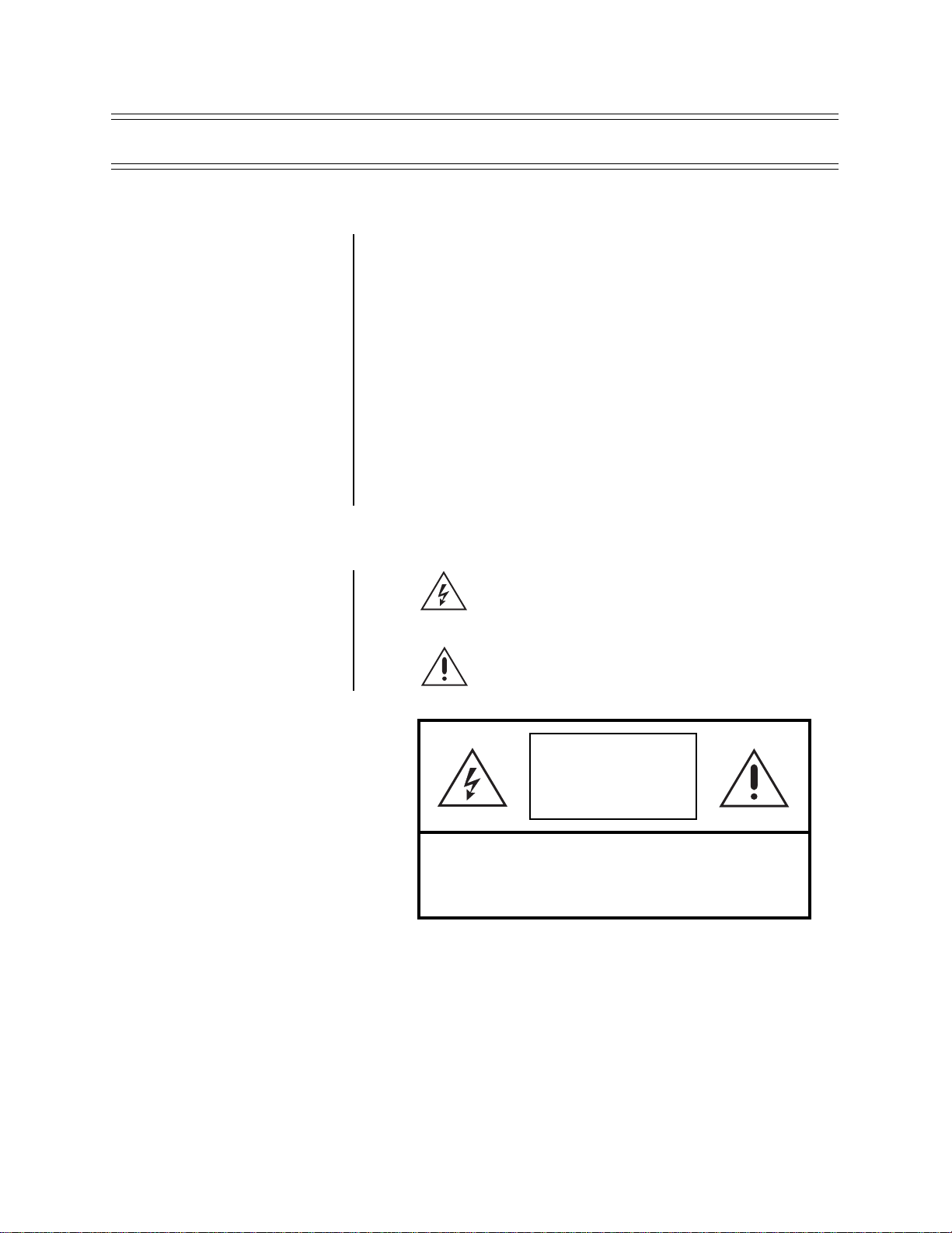
The product and/or manual may bear the following marks:
This symbol indicates that dangerous voltage constituting a
risk of electric shock is present within this unit.
This symbol indicates that there are important operating and
maintenance instructions in the literature accompanying this
unit.
CAUTION:
RISK OF
ELECTRIC SHOCK.
DO NOT OPEN.
TO REDUCE THE RISK OF ELECTRICAL SHOCK,
DO NOT REMOVE COVER. NO USER-
SERVICEABLE PARTS INSIDE. REFER SERVICING
TO QUALIFIED SERVICE PERSONNEL.
CAUTION:
Please thoroughly familiarize yourself with the information
in this manual prior to installation and operation.
3
Page 4

2.0 DESCRIPTION
Environmental enclosures in the TC9346A Series are used with pan/tilt units or
fixed mounts.
The enclosures are constructed of aluminum.
You can install cameras with either fixed focal length lenses or motorized zoom
lenses. All models ha v e an adjustable camer a sled to accommodate different siz es
of cameras and lenses.
2.1 MODELS
TC9346A Environmental enclosure with rear-opening lid. Lid has gas
TC9346A-1 TC9346A with 120 VAC thermostatically controlled heater and
TC9346A-2 TC9346A with 24 VAC thermostatically controlled heater and
TC9346A-3 TC9346A with 230 VAC thermostatically controlled heater and
spring to hold it open. 29-inch (73.66 cm) length.
blower.
blower.
blower.
2.2 OPTIONAL ACCESSORIES
You can order the following optional accessories for the TC9346A Series enclosures:
BK57-1* Blower kit, 120 VAC, 15 watts
BK57-2* Blower kit, 24 VAC, 10 watts
BK57-3* Blower kit, 230 VAC, 15 watts
HK57-1* Heater kit, 120 VAC, 90 watts
HK57-2* Heater kit, 24 VAC, 50 watts
HK57-3* Heater kit, 230 VAC, 70 watts
O/I-PCB Circuit board with thermostats
O/I-LPP* Preset position lens wire harness (must be used with O/I-PCB)
O/I OUTLET* 120 VAC electrical outlet (must be used with O/I-PCB)
SS5729 Sun shroud
TI57 Thermal insulation kit
WD57-1* Window defroster and defogger kit, 120 VAC, 30 watts
WD57-3* Window defroster and defogger kit, 230 VAC, 30 watts
WD57-2* Window defroster and defogger kit, 24 VAC, 30 watts
WW5729-1** Window wiper kit, 120 VAC, 15 watts
WW5729-2** Window wiper kit, 24 VAC, 15 watts
WW5729-3** Window wiper kit, 230 VAC, 15 watts
* These accessories are factory wired with a plug-in connector for use with the
O/I-PCB. The O/I-PCB is included with all -1/-2/-3 models. You must order one
O/I-PCB if you are using a basic enclosure (TC9346A) with these optional
accessories.
** Factory installed option only; consult factory for availability.
4
Page 5
3.0 INSTALLATION
1. Unlatch and raise the enclosure lid. The gas spring will hold the lid in place
when it is fully opened.
2. Remove the camera sled from the rail:
a. Loosen the screws.
b. Slide the sled so that the screws are in the large part of the mounting
slots.
c. Remove the sled.
d. Remove the parts tied to the sled.
3. TC9346A-1, -2, -3 Models Only
If you are installing the enclosure in a marine or high-moisture environment,
make the following modifications to your enclosure:
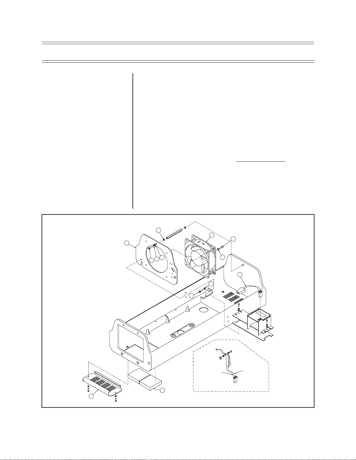
Refer to Figure 1 for an exploded assembly diagram of the blower assembly.
a. Disconnect the electrical plug (3) from the fan (4).
b. Remove the three sets of screws and washers (A, B , and C) that secure
the fan plate (5) and fan (4) to the enclosure.
C
5
C
B
A
A
2
1
4
B
TO FAN
RED
22 GA. (1 FT.)
D
B
3
TO PC BOARD
24 VAC MODELS
BLACK
22 GA. (1 FT.)
Figure 1. Exploded Assembly Diagram for Blower and Circuit Board
5
Page 6

c. Remove the four screws and washers (B and D) that secure the fan to
the fan plate.
d. Turn the fan around so that it blows toward the viewing window (refer to
the arrows on the fan).
e. Reinstall the fan on the fan plate.
f. Reinstall the fan plate and fan in the enclosure.
g. Reconnect the electrical plug on the fan.
h. Close the enclosure lid.
i. On the bottom of the enclosure, remove the vent grill (1) and filters (2) at
the front of the unit. Replace the grill with one of the v ent cov ers that was
attached to the camera sled as loose equipment.
j. On the bottom of the enclosure, attach the other vent plate over the grill
at the rear of the unit.
k. Open the enclosure lid.
4. If you are going to wire the enclosure with cable, remov e the wiring glands and
nuts from the parts bag and install them in the bottom of the enclosure. If you
are going to wire the enclosure with conduit, do not install the glands.
5. Mount the camera/lens to the sled with the 1/4-20 Phillips-head screws that
are provided in the parts bag. You can mount the camera to either side of the
U-shaped sled, depending on the camera height required.
6. There are two threaded mounting holes on the bottom of the enclosure. Mount
the enclosure to a pan/tilt assembly or fixed mount with 1/4-20 screws with
threads that do not exceed 5/8 of an inch (1.59 cm) in length (not supplied with
the enclosure).
7. Install the sled and camera/lens in the enclosure:
a. If the camera’s lens is adjustab le, extend the lens to its maxim um length.
b. Place the sled over the mounting screws in the enclosure.
c. Slide the sled forward until the camera’s lens almost touches the window .
d. Tighten the screws to secure the camera sled to the enclosure.
8. Wire the video output from the camera.
9. If you are going to synchronize cameras, wire the camera’s synchronization
connection.
10. If your camera has a motorized zoom lens control, wire it.
TC9346A Model Only – Wire the camera’s lens control directly to the lens
controller.
TC9346A-1, -2, -3 Models Only
Refer to Figure 2 and wire the motorized zoom lens control as follows:
a. Connect or wire the lens control from the camera to the LENS or LENS
CONTROL connector on the circuit board.
6
Page 7

b. Wire the 10-connector INPUTS terminal on the circuit board to the lens
controller as follows:
• Lens Common - Connector 1
• Focus - Connector 2
• Zoom - Connector 3
• Iris - Connector 4
• Preset Common - Connector 5
• Preset Focus - Connector 6
• Preset Zoom - Connector 7
• Preset High - Connector 8
11. TC9346A-1, -2, -3 Models Only
Refer to Figure 2 and connect the camera’s power input to the circuit board.
There are two ways to supply power to the camer a - when the po wer requirements for the camera and enclosure’ s accessories are the same (for e xample,
if the camera and accessories use 24 VAC), and when the power requirements for the camera and the enclosure’s accessories are different (for example, if the camera uses 24 VAC and the accessories use 120 VAC).
WARNING:
damage possible.
Camera
You
can damage your camera
if you connect it to the
wrong connector.
If your camera will use the same
power as the enclosure, plug the
camera into the CAM 1 socket on
the circuit board.
If your camera’ s voltage will be different from the enclosure’ s voltage,
plug the camera into the CAM 2
socket.
DO NOT
plug the camera
into the CAM 1 socket or you can
damage your camera. CAM 1 has
enclosure voltage on it.
BE CAREFUL - REMEMBER
CAM 1 IS ENCLOSURE
POWER
NEVER PLUG YOUR CAM-
ERA INTO CAM 1 IF THE
CAMERA’S VOLTAGE IS
DIFFERENT FROM THE
ENCLOSURE’S VOLTAGE.
When the power requirements are the same, there are two ways to connect
power:
(1) A three-pin plug is supplied as loose equipment. Connect the wires from
the plug to the camera as follows:
Brown - AC HI
Blue - AC NT
Green - Ground
Connect the plug to the CAM 1 socket on the circuit board (remove the
plastic cover over the power supply section of the circuit board).
or
(2) If both the camera and enclosure use 120 VAC and you ordered the op-
tional 120 VAC electrical outlet accessory (O/I-OUTLET), connect the
120 V A C plug to the camera and the three-pin plug to CAM 1 (remov e the
plastic cover over the power supply section of the circuit board).
When the power requirements are different, connect the wires from the twopin plug, which is supplied as loose equipment, to the camera as follows:
Brown - AC HI
Blue - AC NT
Connect the plug to the CAM 2 socket on the circuit board.
12. Wire power to the enclosure to operate the camera.
TC9346A Model Only – Wire power directly to the camera. If you are using
24 VAC, refer to Table A to determine the size of wire to use.
TC9346A-1, -2, -3 Models Only
• CAM 1 - If the camera’s power input is connected to CAM 1 on the circuit
board, go to step 13.
• CAM 2 - If the camera’s power input is connected to CAM 2 on the circuit
board, wire power for the camera as follows:
a. Connect AC high to connector 9 of the 10-connector INPUTS terminal
block (goes to the brown wire in the CAM 2 connector).
b. Connect AC neutral to connector 10 of the 10-connector INPUTS termi-
nal block (goes to the blue wire in the CAM 2 connector).
7
Page 8

13. TC9346A-1, -2, -3 Models Only
Wire power to the enclosure to operate accessories (and the camera if its
power is connected to CAM 1 on the circuit board) as follows:
a. Remove the plastic cover over the power supply section of the circuit
board.
b. Connect AC high to AC HI of the 3-connector terminal block.
c. Connect AC neutral to AC NT of the 3-connector terminal block.
d. Connect ground to GND of the 3-connector terminal block.
e. Reinstall the plastic cover over the power supply section of the circuit
board.
If the camera’s power is connected to CAM 1 on the circuit board, add the
camera’s wattage to the power consumption of the accessories to determine
the size of wire to use. If you are using 24 VAC, refer to Table A to determine
the size of wire to use. Here are the wattages for the accessories:
Defrosters for all enclosures - 30 watts
Wipers for all enclosures - 15 watts
Blowers for 120 VAC enclosures - 15 watts
Blowers for 24 VAC enclosures - 10 watts
Blowers for 230 VAC enclosures - 15 watts
Heaters for 120 VAC enclosures - 90 watts
Heaters for 24 VAC enclosures - 50 watts
Heaters for 230 VAC enclosures - 70 watts
14. Adjust the camera focus and iris, if necessary.
15. Close the enclosure lid.
8
Page 9

KIT # BK57-2
KIT # BK57-1 (120 V)
KIT # BK57-3 (230 V)
FAN
24 VDC
FAN
120/230 V
PCB9000277ASSY
RED
BLK
RED
BLK
1 2
PLUG
1 2
PLUG
BLK
BLK
PLUG
123
4
WHT
WHT
RED
HEATER
24/120/230 V
HEA TER
24/120/230 V
RED
KIT # HK57-1
KIT # HK57-2
KIT # HK57-3
DEFROSTER
24/120/230 V
KIT # WD57-1
KIT # WD57-2
KIT # WD57-3
WHT
WHT
PLUG
1
2
KIT # WW57-1, -3
TO SWITCH FROM -1, TO -3,
USE JUMPER ON PC BOARD
PCB9000275
120/230 VAC
M
BLK
WHT
BLU
1 2 3 4
PLUG
BLU
WHT
BLK
BLK
BLK/WHT
BLU
BLU/WHT
BRN
BRN/WHT
TRF21240.70.7CM
BLU
WHT
BLK
BLK
WHT
BLU
KIT # WW57-2
PCB9000275
24 VAC
M
1 2 3 4
PLUG
CAUTION
HIGH
VOLTAGE
WIPEON
WASH ON
W/W
W/W
DEF
CAM 1
HTR FAN
FAN
1
1
1
1
P7
P5
P2
TB2
TH1
TH2
TB4
P6
TB3
HTRS
SPARES
AC
HI NT GND 1 2
1
1 2 3 4 5 6 7 8 9 10
PCB9000276 (O/I-PCB)
LENS CONTROL
LENS
J1
5
INPUTS
1
LENS
COM
FOCUS
ZOOM
IRIS
PRST
COM
PRST
FOCUS
PRST
ZOOM
PRST
HI
CAM
CAM
TB1
1
P1
P3
1
1 2
CAM 2
WHT/ORG
WHT/BRN
WHT/RED
WHT/BLU
BLK/WHT
YEL/WHT
RED/WHT
GRN/WHT
LENS CONN W/PRESETS
(SUPPLIED WITH PCB)
LENS
CONN
PLUG
1 2
PLUG
1 2 3
PLUG
1 2 3
OUTLET
PLUG
120 V
OPTIONAL
CAMERA
POWER
(SUPPLIED
WITH PCB)
*
CAMERA POWER
24/120/230 VAC
(SUPPLIED
WITH PCB)
*
KIT # O/I-OUTLET
LENS CONN OPTIONS
CPC CONN.
KIT # O/I-IPP
4 3 2 1 8 9 7 6 5
NOT USED
BRN
BLU
BRN
BLU
GRN
BLK
WHT
GRN
* CONNECT CAM 1 TO CAMERA WHEN THE CAMERA’S
POWER IS THE SAME AS THE AC POWER INPUT.
CONNECT CAM 2 TO CAMERA WHEN THE CAMERA’S
POWER IS DIFFERENT FROM THE AC POWER INPUT.
Figure 2. TC9346A Series Input Wiring Diagr am
9
Page 10

T ab le A. 24 V AC Wiring Distances
The following are the recommended maximum distances for 24 VAC applications
and are calculated with a 10-percent voltage drop. (Ten percent is generally the
maximum allowable voltage drop for AC-powered devices.)
EXAMPLE:
An enclosure that requires 80 vA and is installed 35 feet
(10 m) from the transformer would
require a minimum wire gauge of
20 AWG.
NOTE:
Distances are calculated in
feet; values in parentheses are
meters.
Wire Gauge
20 18 16 14 12 10
10 283 451 716 1142 1811 2880
(86) (137) (218) (348) (551) (877)
20 141 225 358 571 905 1440
(42) (68) (109) (174) (275) (438)
30 94 150 238 380 603 960
(28) (45) (72) (115) (183) (292)
40 70 112 179 285 452 720
(21) (34) (54) (86) (137) (219)
50 56 90 143 228 362 576
(17) (27) (43) (69) (110) (175)
60 47 75 119 190 301 480
(14) (22) (36) (57) (91) (146)
70 40 64 102 163 258 411
(12) (19) (31) (49) (78) (125)
80 35 56 89 142 226 360
(10) (17) (27) (43) (68) (109)
90 31 50 79 126 201 320
(9) (15) (24) (38) (61) (97)
100 28 45 71 114 181 288
(8) (13) (21) (34) (55) (87)
110 25 41 65 103 164 261
(7) (12) (19) (31) (49) (79)
120 23 37 59 95 150 240
Total vA consumed
(7) (11) (17) (28) (45) (73)
130 21 34 55 87 139 221
(6) (10) (16) (26) (42) (67)
140 20 32 51 81 129 205
(6) (9) (15) (24) (39) (62)
150 18 30 47 76 120 192
(5) (9) (14) (23) (36) (58)
160 17 28 44 71 113 180
(5) (8) (13) (21) (34) (54)
170 16 26 42 67 106 169
(4) (7) (12) (20) (32) (51)
180 15 25 39 63 100 160
(4) (7) (11) (19) (30) (48)
190142337 6095151
(4) (7) (11) (18) (28) (46)
200142235 5790144
(4) (6) (10) (17) (27) (43)
Maximum distance from transformer to load
10
Page 11

4.0 OPERATION
If your enclosure has a thermostatically controlled blower, the thermostat is set to
turn the fan on between 77° and 93°F (25° and 34°C) and to turn the fan off between 62° and 78°F (17° and 26°C).
If your enclosure has thermostatically controlled heaters or defroster, the thermostat is set to turn them on between 42° and 58°F (6° and 14°C) and to turn them off
between 72° and 88°F (22° and 31°C).
11
Page 12

5.0 MAINTENANCE AND TROUBLESHOOTING
5.1 MAINTENANCE
Perform the following maintenance at regularly scheduled intervals to prolong the
operational life and appearance of the equipment.
1. Clean the window with a mild non-abrasive detergent in water and a soft cloth
to maintain picture clarity.
2. If your enclosure has a blower, clean the foam filters as follows:
a. On the bottom front of the enclosure, remove the two screws in the vent
grill.
b. Remove the vent grill and tak e out the filters .
c. Clean the filters with warm water and mild detergent, dry thoroughly, and
replace them in the grill.
d. Reinstall the vent grill.
To order replacement filters, use the part number EH550010045.
5.2 TROUBLESHOOTING
If your enclosure has the optional circuit board (O/I-PCB) and you need to troubleshoot it, Figures 3 through 5 show the wiring, component locations, and layout of
traces.
12
Figure 3. Component Locations for Optional Circuit Board
Figure 4. Layout of Traces on Optional Circuit Board
Page 13

REFER TO FIGURE 3 FOR COMPONENT LOCATIONS
ENCLOSURE CIRCUIT BOARD
Figure 5. Wiring Diagram for Optional Circuit Board (O/I-PCB)
13
Page 14

6.0 SPECIFICATIONS
ELECTRICAL
Input Voltage: 24, 120 or 230 VAC, 50/60 Hz
Electrical
Connections: One each of the following when equipped with optional circuit
board (O/I-PCB):
3-connector terminal block for power input
6-pin lens connector
9-connector terminal block for lens wiring
10-connector terminal block for camera/lens wiring
2-connector terminal block for spare connections
3-pin socket for camera power input
2-pin socket for optional camera power input
2-pin socket for blower
2-pin socket for defroster
4-pin socket for heaters
4-pin socket for wiper
2-pin socket for wiper control
Input Power
Heater -1: 90 watts
Heater -2: 50 watts
Heater -3: 70 watts
Defroster -1, -2, -3: 30 watts
Blower-1, -3: 15 watts
Blower -2: 10 watts
Wiper -1, -2, -3: 15 watts
MECHANICAL
Construction: Aluminum, 0.080-inch (0.02 cm) thick (Enclosure body and lid)
Finish: Polyester vinyl powder coat
Cable Entry: Two UL-approved glands on bottom of enclosures; maxi-
Window: Glass, 0.25-inch (0.64 cm) thick
Window Viewing Area: 3.8" H x 4.8" W (9.65 x 12.19 cm)
Camera Mounting: Removable camera sled that can be inverted to accommo-
Max. Camera and
Lens Size
TC9346A: 28" L x 7.5" W x 5.5" H (71.12 x 19.05 x 13.97 cm)
TC9346A-1, -2, -3: 21.5" L x 6.25" W x 5.5" H (54.61 x 15.88 x 13.97 cm)
Latches: Stainless Steel
Dimensions: See Figure 6
mum cable diameter 0.47 inch (1.19 cm). Will accept 1/2-inch
(1.27 cm) conduit without glands.
date various heights of cameras and lenses
14
Weight Unit Shipping
TC9346A: 16 lb (7.26 kg) 18 lb (8.16 kg)
TC9346A-1, -2, -3: 18 lb (8.14 kg) 20 lb (9.07 kg)
Page 15

GENERAL
NEMA Rating: 3R (4 when vent cover plates are used)
iec 144 rating: IP32 (IP56 when vent cover plates are used)
Environment: Indoor/outdoor -10° to 120°F (-23° to 49°C)
(Design and product specifications subject to change without notice.)
10.55
(26.79)
5.25
(13.35)
4.25
(10.79)
8.60
(21.84)
ABC
29.00 14.50 32.50
(73.66) (36.83) (82.55)
6.19
(15.72)
3.06
(7.78)
C
A
B
NOTE: VALUES IN PARENTHESES ARE CENTIMETERS; ALL OTHERS ARE INCHES
Figure 6. TC9346A Dimension Dra wing
15
Page 16

© 2004 Bosch Security Systems GmbH
3935 890 12912 04-33 | Updated August 10 2004 | Data subject to change without notice.
Bosch Security Systems, Inc.
850 Greenfield Road
Lancaster, PA 17601 USA
Tel: 800-326-3270
Fax: 1-717-735-6560
www.boschsecuritysystems.com
Bosch Security Systems B.V.
P.O. Box 80002
5600 JB Eindhoven
The Netherlands
Tele +31 4027 80000
Bosch Security Systems Pte Ltd.
38C Jalan Pemimpin
Singapore 577180
Republic of Singapore
Tel: 65 (6) 319 3486
 Loading...