

Bosch TC9320, TC9320C Instruction Manual
TC9320, TC9320C
Instruction Manual
EN Indoor Ceiling
Housings
IMPORTANT SAFEGUARDS
UNPACKING
1.Read Instructions - All the safety and operating
instructions should be read before the unit is operated.
2.Retain instructions - The safety and operating
instructions should be retained for future reference.
3.Heed Warnings - All warnings on the unit and in the
operating instructions should be adhered to.
4.Follow Instructions - All operating and user instructions
should be followed.
5.Electrical Connections - Only a qualified electrician
should make electrical connections.
6. Attachments - Do not use attachments not recom
mended by the product manufacturer as they may
cause hazards.
7. Cable Runs - All cable runs must be within permissible
distance.
8.Mounting - This unit must be properly and securely
mounted to a supporting structure capable of sustaining
the weight of the unit. Accordingly,
a. The installation should be made by a qualified
installer.
b. The installation should be in compliance with local
codes.
c. Care should be exercised to select suitable hard
ware to install the unit, taking into account both
the composition of the mounting surface and the
weight of the unit. Be sure to periodically examine
the unit and the supporting structure to make sure
that the integrity of the installation is intact.
Failure to comply with the foregoing could result in the
unit separating from the support structure and falling,
with resultant damages or injury to anyone or anything
struckby the falling unit.
Unpack carefully. This is a mechanical equipment and
should be handled carefully.
If an item appears to have been damaged in shipment,
replace it properly in its carton and notify the shipper. If any
items are missing, notify your Bosch Sales Representa-
tive or Customer Service.
The shipping carton is the safest container in which the unit
may be transported. Save it for possible future use.
SERVICE
If the unit ever needs repair service, the customer should
contact the nearest Bosch Service Center for authoriza-
tion to return and shipping instructions.
Service Centers
U.S.A.: 800-366-2283 or 717-735-6638
Fax: 800-366-1329 or 717-735-6639
CCTV Spare Parts
U.S.A: 800-894-5215 or 408-956-3853 or 3854
Fax: 408-957-3198
E-mail:BoschCCTVparts@ca.slr.com
SAFETY PRECAUTIONS
CAUTION
RISK OF ELECTRIC
SHOCK!
CAUTION: TO REDUCE RISK OF ELECTRICAL SHOCK,
DO NOT OPEN COVERS. NO USER SERVICEABLE
PARTS INSIDE. REFER SERVICING TO QUALIFIED
SERVICE PERSONNEL.
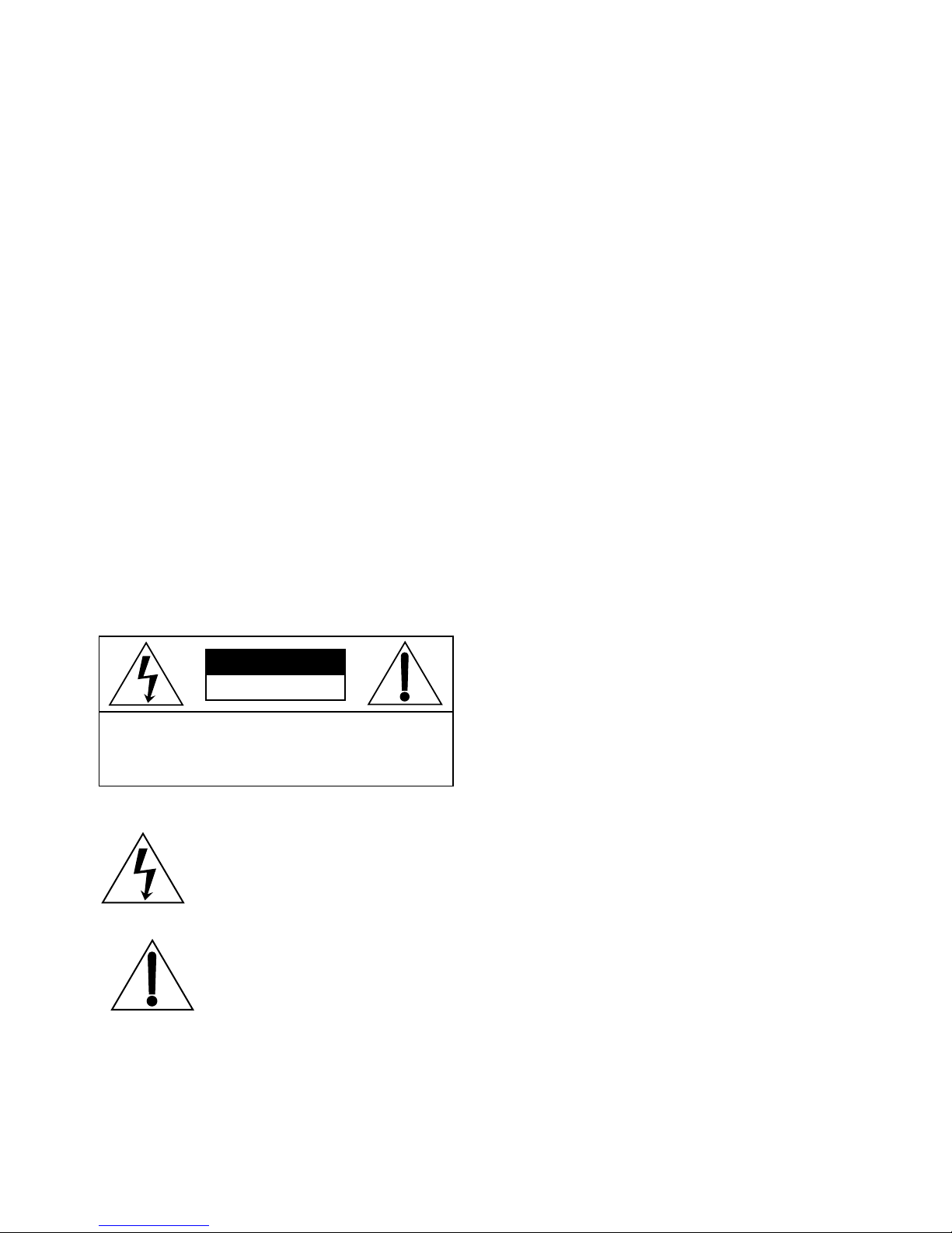
The lightning flash with an arrowhead
symbol, within an equilateral triangle,
is intended to alert the user to the
presence of non-insulated "
dangerous voltage" within the
product's enclosure that may be of
sufficient magnitude to constitute a
risk of electric shock to persons.
The exclamation point within an
equilateral triangle is intended to
alert the user to presence of
important operating and
maintenance (servicing) instructions
in the literature accompanying the
appliance.
- 2 -
MODELS TC9320/TC9320C
Description: A discreet housing system designed for outdoor
applications. Heaters and blowers are available as options.
Designed for pendant mounting, but can be wall, pole, or roof
mount with optional brackets. Unit is also available with liner
assembles with "L" added to part number.
Contents:
(1) ceiling coupling
(1) 1/4-20 housing coupling
(1) rubber gasket
(1) black plastic shroud
(1) upper white plastic housing
(1) acrylic dome
(1) metal pan/tilt mounting plate w/ quick
release plate
(1) black inner liner (L model only)
(2) liner support arms (L model only)
(1) terminal block bracket
(1) terminal block w/ cover and clips
(1) housing packet
(4) 2.5" PVC spacers w/ mounting hardware for
mounting plate.
(1) toolhead driver (for security screws on
acrylic dome)
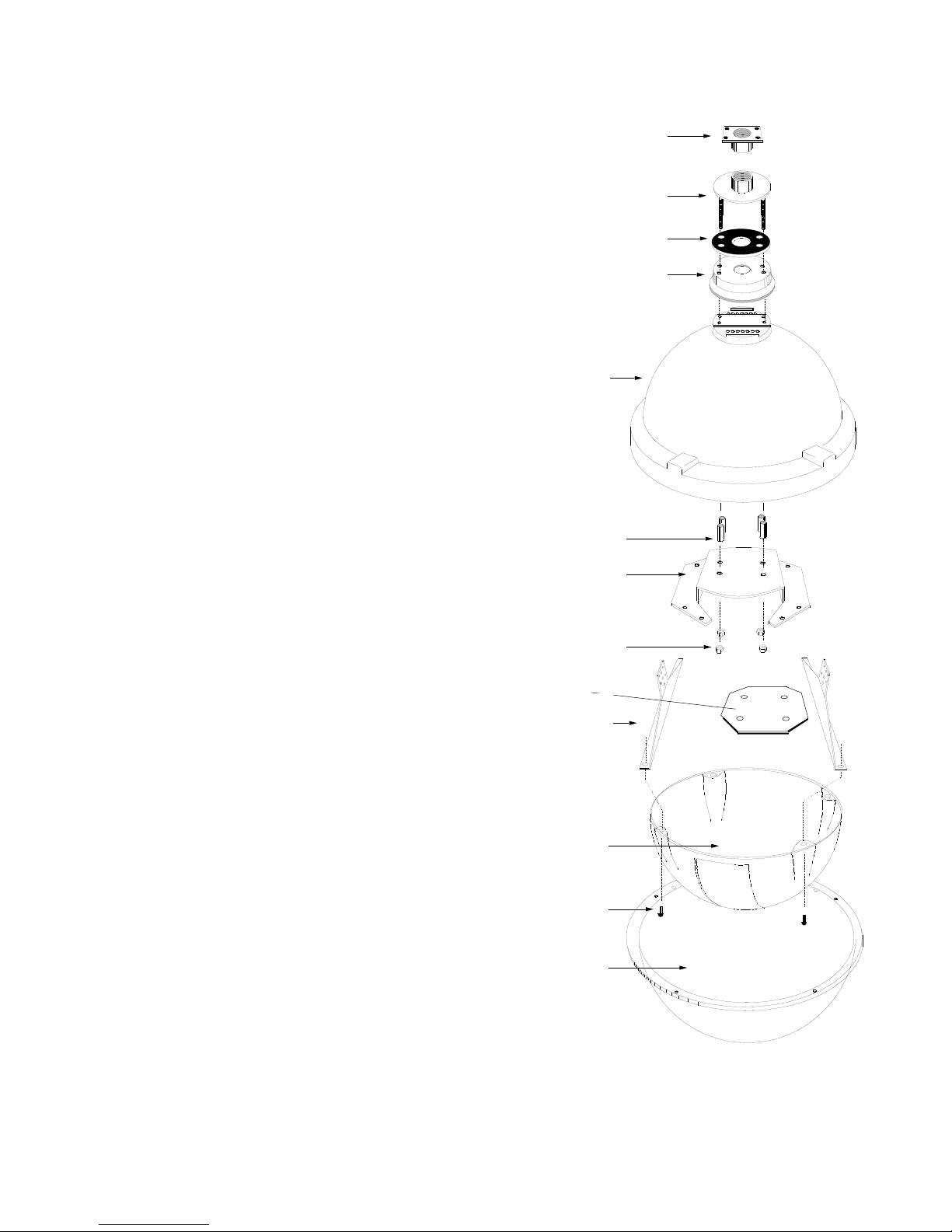
1. Remove contents from box. While unit is still "on the bench",
pre-assemble the upper housing, refering to Fig. 1. Slide the
rubber gasket over the 1/4-20 threaded studs on the metal
housing coupling. Next slide the black shroud onto the coupling,
followed by the white upper housing.
2. Attach the terminal bracket to the pan/tilt mounting bracket,
according to the instructions on page 3.
Figure 1
PRODUCT INSTRUCTIONS
Ceiling Coupling
CEILING COUPLING
32-VL135
HOUSING COUPLING
Housing Coupling
32-VL448
RUBBER GASKET
SHROUD
White Upper Housing
21-TOVL20
WHITE UPPER
HOUSING
2.5" SPACER
P/T Mounting Bracket
P/T MOUNTING
30-VL402
PLATE
3. Open the housing packet and remove the (4) 2.5" spacers
and place them inside the housing over the threaded studs.
Remove the quick release plate from the mounting bracket and
slide the bracket into position over the threaded studs, a shown in
Fig. 1.
NOTE: If you are using optional heaters and/or blower, refer to
electrical accessories section on page 3 prior to installing mounting bracket.
4. Using split lockwashers and 1/4-20 hex nuts, secure this assembly together.
5. Connect mounting bracket to desired location. Bring all
necessary electrical connections down through the pipe, leaving
enough wire hanging out to feed into the housing as it is being
connected to the pipe.
6. Thread upper housing assembly from steps 1 and 2 onto end
of 1.5" pipe until unit is tight and secure. Seal pipe threads and
rubber gasket with silicone.
HEX NUTS AND
Hex Nuts & Washers
WASHERS
P/T Quick Release Plate
30-VL407
METAL LINER
ARMS
Metal Liner Arms
30-VL384
BLACK INNER
LINER
Black Inner Liner
20-LNSS20
BLACK NYLON
PUSH SCREWS
X-mas Tree Fasteners
94-FSXM01
ACRYLIC
DOME
95-FSTD01 - Toolhead Driver
- 3 -
 Loading...