

Page 1
Instruction Manual
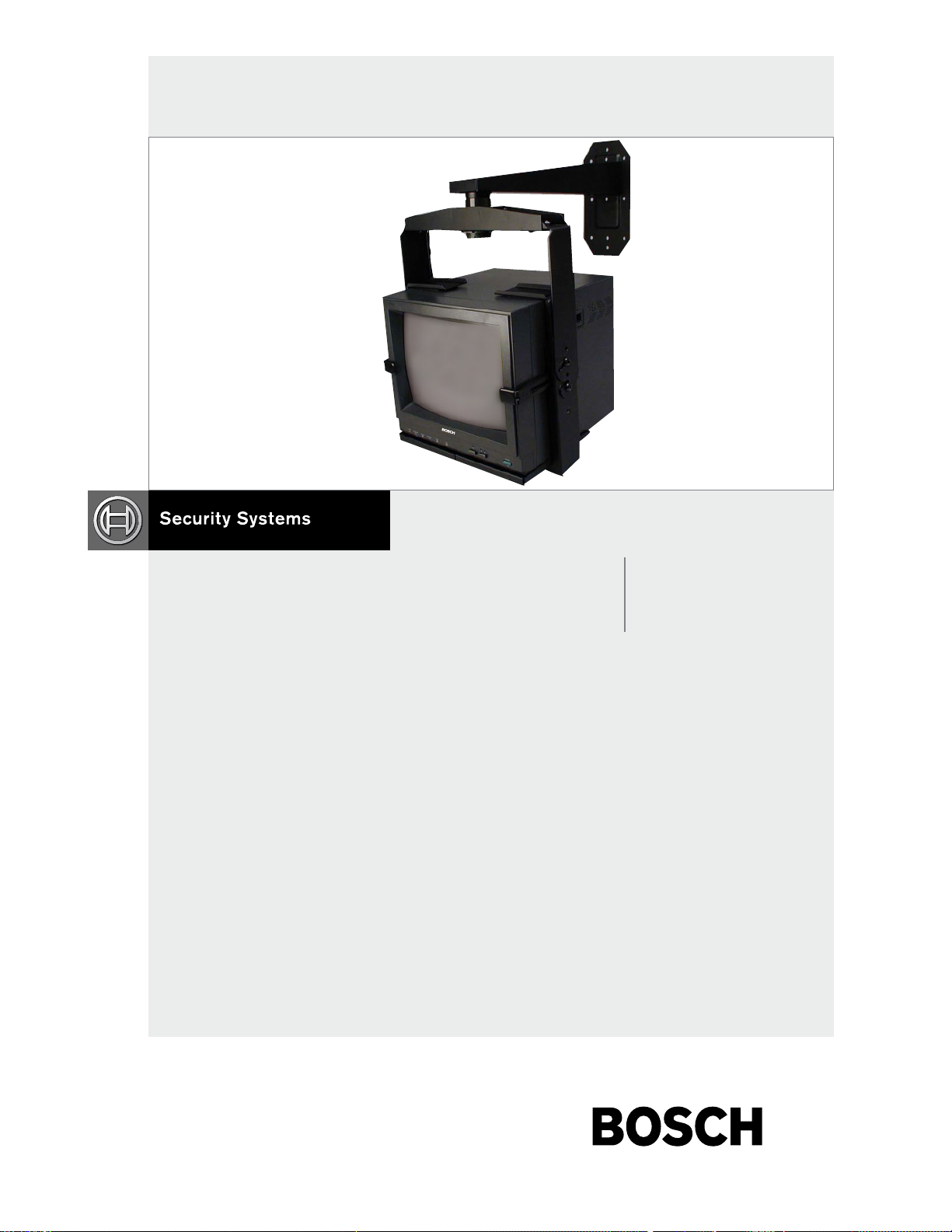
EN Monitor Mounts
TC9217MM-W, TC9220MM-W, TC9227MM-W
1 of 11
ISSUED: 06-25-99 SHEET #: 039-9003-8 02-08-05
Page 2
TC9217MM-W, TC9220MM-W, TC9227MM-W | Instruction Manual |
EN
|
2
Bosch Security Systems | February 3, 2005
MONITOR MOUNT COMPATIBILITY CHART
For Bosch LTC Series Monitors
Bosch Monitor Ceiling Wall
Model No. Mount Mount
Monochrome
LTC 2009/51, /61 MM3000 TC9209MM-W
LTC 2012/51, /61 MM3000 TC9209MM-W
LTC 2017/50, /60 TC9217MM-C TC9217MM-W
LTC 2020/90 TC9220MM-C TC9220MM-W
Color
LTC 2810/90, /91 TC9217MM-C TC9217MM-W
LTC 2813/90 TC9217MM-C TC9217MM-W
LTC 2814/90 TC9217MM-C TC9217MM-W
LTC 2821/90, /91 TC9220MM-C TC9220MM-W
LTC 2910/90 MM3000 TC9209MM-W
LTC 2915/91 TC9217MM-C TC9217MM-W
LTC 2917/91 TC9217MM-C TC9217MM-W
LTC 2919/90 TC9220MM-C TC9220MM-W
27ST220L TC9227MM-C TC9227MM-W
Installation Hint for TC9217MM, TC9220MM, and TC9227MM Series Monitor Mounts, RE: Step 4.
For proper center of gravity alignment of Bosch monitors on the bottom support tray, a recommended starting point is to
use the third (3rd) square hole from the front edge of the tray to mount the vertical support arm using pin E.
SERVICE
If the unit needs servicing, contact the nearest Bosch Security Systems Service Center for authorization to return
and shipping instructions.
Service Centers
USA
Phone: 800-366-2283 or 717-735-6638
Fax: 800-366-1329 or 717-735-6639
CCTV Spare Parts
Phone: 800-894-5215 or 408-956-3853 or 3854
Fax: 408-957-3198
E-mail: BoschCCTVparts@ca.slr.com
Canada
Phone: 514-738-2434
Europe, Middle East & Asia Pacific Region
Phone: 32-1-440-0711
For additional information, see www
.boschsecurity.com.
2 of 11
ISSUED: 06-25-99 SHEET #: 039-9003-8 02-08-05
Page 3
Installation and Assembly
BOSCH Monitor Wall Mounts
BOSCH
Models: TC9217MM-W , TC9220MM-W,
TC9227MM-W
This product is intended for use with UL
R
Product is UL rated up to ___ TV
sizes, per attached chart
Model #:
TC 9 217 MM-W
TC 9 220 MM-W
TC 9 227 MM-W
Listed products and must be installed by a
qualified professional installer.
TV size
17"
21"
27"
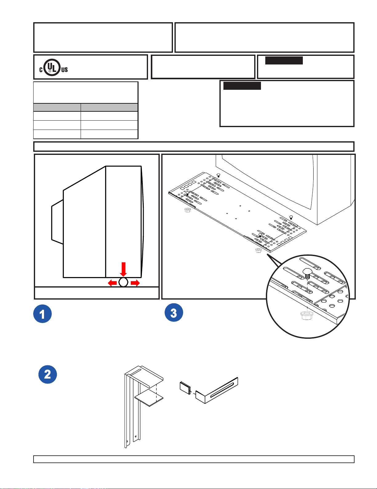
Each monitor mount is for use with a single TV or monitor of a specified size only.
SIDE VIEW
TV
Before you start make sure all parts
shown (see parts list, page 9) are
included with your bracket.
IMPORTANT! If attaching a VCR Mount
carefully study both product instruction sheets
before assembly. The interface bracket
(included with the VCR Mount) must be
attached during monitor mount assembly to
avoid disassembly later.
A
IMPORTANT! Read entire
instruction sheet before you
start installation and assembly .
TV
CENTER OF
GRAVITY
FLOOR
Place TV onto a piece of pipe as
shown. (Pipe should be a few inches
wider than the TV.) Roll TV back and
forth to find the balance point. This is
the center of gravity. Mark the center
of gravity on the side of the TV.
Attach adhesive
pads (X) to top
clamps (Q).
Insert plastic
covers (CC) onto
ends of anti-rollout
hooks (R).
Q
X
Adjust support tray (A, three
pieces) to match width of TV.
Lock support tray using four
carriage bolts (B), washer/
nut combo (C). Tighten
securely.
CC
R
B
C
3 of 12
ISSUED: 06-25-99 SHEET #: 039-9003-8 02-08-05
Page 4
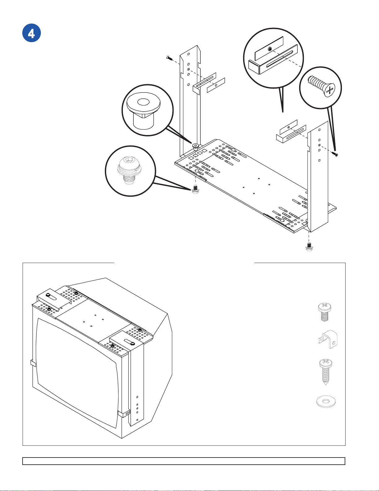
Attach support tray (A)
to vertical support arms
(P) as shown.
Note: Choose the square
hole which aligns closest
with the center of gravity
mark on the TV (as
determined in step 1).
Attach anti-rollout hooks
(R) as shown using M6
screws (Z) and retainer
bars (Y). Note: Extruded
side of retainer bar (Y)
goes towards anti-rollout
hook (R).
Hand tighten only.
E
P
R
Y
Y
R
Z
Y
R
A
TV
(UPSIDE DOWN)
J
O P T I O N A L
TV BOTTOM
Although top clamps (Q) and anti-rollout
hooks (R) [see step 7] will provide more than
adequate support for the TV, some installers
may wish to also attach the support tray to
the TV bottom.
Using uni-clips (G) and M5 screws (F) (see
instruction card in fastener pack), or #10 x
3/4" particle board screws (H) and washers
(I) (for attachment to mounting bosses if
present), or a combination of both, attach
support tray (A) to TV bottom. [To do this
place TV upside down on a flat stable
surface and position support tray upside
down on TV bottom.] Attach at four places
as close to the four corners of the TV bottom
as possible.
A
P
F
G
H
I
4 of 12
ISSUED: 06-25-99 SHEET #: 039-9003-8 02-08-05
Page 5

For Wood Stud Walls drill three 5/32" (4 mm) dia. holes to a minimum depth of 2.5" (64 mm) into stud center.
Attach wall arm (W) using three #14 x 2.5" (6 mm x 65 mm) wood screws (V).
WARNING
• Tighten wood screws so wall arm is firmly attached, but do not tighten with excessive force! Overtightening can
cause stress damage to wood screws, greatly reducing their holding power. Tighten to 80 in • lb (9 N.M.) maxi-
mum torque.
WOOD
STUD
WALL
W
V
5 of 12
ISSUED: 06-25-99 SHEET #: 039-9003-8 02-08-05
Page 6

WARNING
• When installing BOSCH wall mounts on cinder block, verify that you have a minimum of 1-3/8" of actual concrete
surface in the hole to be used for the concrete anchors. Do not drill into mortar joints! Be sure to mount in a solid
part of the block, generally 1" minimum from the side of the block. Cinder block must meet ASTM C-90 specifications. It is suggested that a standard electric drill on slow setting is used to drill the hole instead of a hammer drill
to avoid breaking out the back of the hole when entering a void or cavity .
• Concrete must be 2000 psi density minimum. Lighter density concrete may not hold concrete anchor .
• Make sure that the wall will safely support four times the combined load of the equipment and all attached hardware and components.
For Concrete Walls use wall arm (W), making sure
that it is level, as a template to mark holes. Drill 1/
4" (6 mm) dia. holes to a minimum depth of 2.5" (64
mm). Insert concrete anchors in holes flush with
wall as shown (right). Place wall arm (W) over
anchors and secure with #14 x 2.5" (6 mm x 65
mm) wood screws (V). Tighten all fasteners.
1
concrete
wall
ACC 204
WARNING
• Tighten wood screws so that wall plate is firmly
attached, but do not overtighten. Overtightening can
damage the screws, greatly reducing their holding
power.
• Never tighten in excess of 80 in • lb (9 N.M.).
• Make sure that mounting screws are anchored into the
center of the studs. The use of an "edge to edge" stud
finder is highly recommended.
WARNING
• Concrete anchors are not intended for attachment to
concrete wall covered with a layer of plaster, drywall,
or other finishing material. If mounting to concrete wall
covered with plaster/drywall is unavoidable, plaster/
drywall (up to 5/8" thick) must be counterbored as
shown below. If plaster/drywall is thicker than 5/8",
custom fasteners must be supplied by installer .
Drill hole(s) and insert anchor(s)
2
Place arm over anchor(s) and secure with screw(s)
wall arm
ACC 204
3
Tighten all fasteners
wall
arm
INCORRECT
plaster/
dry wall
CUT AW A Y VIEW
concrete
wall
arm
CORRECT
plaster/
dry wall
concrete
6 of 12
ACC 204
CONCRETE
WALL
W
V
ISSUED: 06-25-99 SHEET #: 039-9003-8 02-08-05
Page 7

Note: Slots in corners of top clamps (Q) and corners of vertical support arms (P) allow for the installation of safety belt
(model ACC 666, sold separately). If using this belt, install it now.
Q
Q
DETAIL 1
Q
DETAIL 2
R
Z
R
R
P
A
R
P
Position TV onto support tray (A). Position anti-rollout hooks (R) against front edge of TV.
Q
P
K
WARNING
• Each anti-rollout hook (R) should have at least 1/4” of surface contact with the front of the TV. If this is not the
case the support tray (A) must be adjusted smaller [see step 2], or the vertical support arms (P) adjusted inward
[see step 4].
Insert top clamps (Q). Note: Top clamps (Q) fit between rollout protectors (R) and vertical support arms (P)
[DETAIL 1]. Press down on each top clamp (Q) while securely tightening each M6 screw (Z).
By hand, thread one serrated flange head screw (K) into each vertical support arm (P) into one of three threaded
holes [1, 2, or 3; DETAIL 2]. Choose the threaded hole that will allow just enough tilt clearance [see step 9].
Leave about 1/4" of exposed thread.
FIRST: From the top fully thread flush mount tube
(T) into threaded fitting in wall arm or ceiling plate.
Install the wall arm or ceiling plate according to
instructions included with it.
NEXT: Attach right and left tilt brackets (AA & BB)
to horizontal support (S) using four screws &
washer combo (J). Before tightening screws make
sure tilt brackets are adjusted horizontally to align
precisely with screws in the side of vertical support
arms (P). Attach horizontal support (S) to wallarm
or ceiling plate using fiber washers (M & N), spacer
(U, only included with smaller models) and retaining
collar (O). IMPORTANT: Retaining collar (O)
requires a safety screw [refer to DETAIL 3, page 8].
FINALLY: Be sure that hooks in right and left tilt
brackets (AA & BB) are open end forward. Hang the
TV / bracket assembly.
M
O
WMJ 025H
**
U
N
BB
T
CMJ 470,
CMJ 480,
CMJ 490
S
AA
WMJ 018,
WMJ 022
T
*
J
WARNING
P
Wall arms & ceiling plates
*
include their own
instructions. Fixed length
and adjustable extension
columns are also available.
Included with models
**
TC9217MM and
TC9220MM only.
7 of 12
• Do not lift more weight than you can handle!
Use additional manpower or mechanical lifting
equipment to safely lift and hang the TV /
Bracket assembly!
Insert one screw & washer combo (J) through slot
in each tilt bracket (AA & BB). Hand tighten.
ISSUED: 06-25-99 SHEET #: 039-9003-8 02-08-05
Page 8

T
S
F
DETAIL 3
(BOTTOM VIEW)
TIL T CLEARANCE
O
S
When attaching the horizontal support (S) to wall arm or
ceiling plate, carefully thread retaining collar (O) onto end of
flush mount (T) tube (or extension column). Tighten at least
four complete turns ending with one of the small threaded
holes aligned with slot in the end of flush mount tube (T) (or
extension column). Insert and tighten one M5 screw (F).
WARNING
• Set screw (F) is self tapping and may be hard to get
started but is essential to this installation. Failure to
install this screw can cause the mount to fall.
Adjust TV to desired tilt then tighten screws. Maximum tilt
is 30°. If tilt clearance is a problem revisit step 7, DETAIL 2.
WARNING
• Tighten all screws securely .
8 of 12
ISSUED: 06-25-99 SHEET #: 039-9003-8 02-08-05
Page 9

Parts Li st
De scri p ti o n Qty. Par t # Par t # Par t #
left end support t ray 1 128-1023 128-1026 128-1026
A1
right end s upport tray 1 128-1024 128-1027 128-1027
A2
cent er s upport t ray 1 128-1128 128-1134 128-1135
A3
5/16 - 18 x 1/2" carriage bolt 4 520-9207 520-9207 520-9207
B
5/16-18 washer/nut combo 4 530-1016 530-1016 530-1016
C
M10-1.5 x .7 flange nut 2 520-9261 520-9261 520-9261
E
M5 x . 8 x 10 m m s crew 6 520-9250 520-9250 520-9250
F
uni-clip 4 2245-081 2245-081 2245-081
G
#10 x 3/ 4" parti cle board screw 4 500-9006 500-9006 500-9006
H
#10 flat washer 4 540-9400 540-9400 540-9400
I
M10 s oc ket head l oc k/flat was her c om bo s crew 8 520-1041 520-1041 520-1041
J
M10 s errated flange head sc rew 2 520-1105 520-1105 520-1105
K
fiber washer - large inside dia. 1 540-9432 540-9432 540-9432
M
fiber washer - small i ns i de dia. 1 540-9431 540-9431 540-9431
N
reta i ni ng col l ar 1 1800-375 1800-375 1800-375
O
vertic al support arm 2 128-1107 128-1109 128-1111
P
top c l amp 2 128-1138 128-1138 128-1138
Q
anti-rollout hook 2 128-1116 128-1116 128-1116
R
horizont al s upport 1 128-1016 128-1017 128-1018
S
flush mount t ube 1 1446-014 1446-014 1446-014
T
spacer 1 128-0067 128-0067 -
U
#14 x 2 . 5" (6 m m x 65 m m) s crew 4 5S1 -015 -C03 5S1-0 15-C0 3 5S1-01 5-C03
V
si ngle wall arm 1 128-1059 128-1059 128-1069
W
adhesive pads (not s hown) 2 570-0024 570-0024 570-0024
X
retainer bar 2 128-1117 128-1117 128-1117
Y
M6 x 18mm flat phi ll ips s c rew 2 520-1166 520-1166 520-1166
Z
til t brack et right 1 128-1342 128-1337 128-1337
AA
til t brack et left 1 128-1341 128-1336 128-1336
BB
plastic cover for anti -rollout hook 2 590-1055 590-1055 590-1055
CC
TC9217MM-W TC9220MM-W TC9227MM-W
Note: Parts may appear slightly different than illustrated.
R
T
Y
U
P
Y
BB
A1
R
A3
P
X
Q
A2
N
S
M
O
X
B
W
C
AA
Q
V
E
J
Z
F
G
I
H
K
CC
9 of 12
ISSUED: 06-25-99 SHEET #: 039-9003-8 02-08-05
Page 10

Mount
Model
Number
TC9217MM-W
TC9220MM-W
TC9227MM-W
GENERAL WALL MOUNT KIT SPECIFICATIONS
TV/Monitor
Support
Product BOSCH rated
when attached to...
Tray
Depth (D)
10"
(254 mm)
10"
(254 mm)
14"
(356 mm)
10"
(254 mm)
14"
(356 mm)
14"
14"
18" (457 mm) for models TC9217MM-W, TC9220MM-W.
14"
22.5" (572 mm) for models TC9227MM-W.
14"
Screen Size
(330 mm) (432 mm)
(482 mm) (533 mm)
(482 mm) (533 mm)
(635 mm) (686 mm)
(635 mm) (686 mm)
(635 mm) (686 mm)
Reach (R)
(635 mm) (686 mm)
(762 mm) (889 mm)
(686 mm) (889 mm)
13" - 17"
19" - 21"
19" - 21"
25" - 27"
25" - 28"
25" - 27"
14"
(940 mm) (1067 mm)
14"
WARNING
(889 mm) (1067 mm)
• Weight of TV or monitor not to exceed Max. Load
Capacity (BOSCH rating)!
wood
stud
125 lb
(57 kg)
125 lb
(57 kg)
125 lb
(57 kg)
125 lb
(57 kg)
125 lb
(57 kg)
125 lb
300 lb
300 lb
300 lb
300 lb
300 lb
concrete,
cinder block
or brick
150 lb
(65 kg)
150 lb
(65 kg)
150 lb
(65 kg)
150 lb
(65 kg)
150 lb
(65 kg)
150 lb
300 lb
300 lb
300 lb
300 lb
300 lb
0
30
range
R
tilt
wall
TV
support tray
D
10 of 12
ISSUED: 06-25-99 SHEET #: 039-9003-8 02-08-05
Page 11

11 of 12 ISSUED: 06-25-99 SHEET #: 039-9003-8 02-08-05
Page 12

© 2005 Bosch Security Systems GmbH
3935 890 28113 05-05 | February 3, 2005 | Data subject to change without notice.
Americas
Bosch Security Systems
130 Perinton Parkway
Fairport, New York, 14450, USA
Phone: +1 (585) 223 4060
Fax: +1 (585) 223 9180
E-mail: security.sales@us.bosch.com
www.boschsecurity.us
Europe, Middle East, Africa
Bosch Security Systems B.V.
P.O. Box 80002
5600 JB Eindhoven, The Netherlands
E-mail:
ema.securitysystems@bosch.com
http://www.boschsecurity.com
Asia-Pacific
Bosch Security Systems Pte Ltd
38C Jalan Pemimpin
Singapore 577180, Singapore
Phone: +65 319 3488
Fax: +65 319 3499
E-mail:
sg.securitysystems@bosch.com
http://www.boschsecurity.com
11 of 11
ISSUED: 06-25-99 SHEET #: 039-9003-8 02-08-05
 Loading...