

Page 1
Plena Loop Amplifier
Installation and User Instructions
PLN-1LA10en
Page 2

Page 3

Plena Loop Amplifier | Installation and User Instructions | Important safeguards en | 3
Important safeguards
Before you install or operate the Plena Loop Amplifier,
you must read the Important Safety Instructions. The
Important Safety Instructions are supplied together with
the Plena Loop Amplifier.
Bosch Security Systems | 2007-08 | 9922 141 50672en
Page 4

Plena Loop Amplifier | Installation and User Instructions | Acknowledgements en | 4
Acknowledgements
Bosch Security Systems thanks the NVVS (Dutch
Association of Hard of Hearing People) for the valuable
information that was provided during the development
of the Plena Loop Amplifier and the creation of the
Installation and User Instructions.
Bosch Security Systems | 2007-08 | 9922 141 50672en
Page 5
Plena Loop Amplifier | Installation and User Instructions | About this manual en | 5
About this manual
Function
The Installation and User Instructions gives the
installers and operators the necessary data to install,
configure and operate the Plena Loop Amplifier.
Digital version
The Installation and User Instructions is available as a
digital file (Portable Document File, PDF).
When the PDF refers you to a location that contains
more data, you can click the text to go there. The text
contains hyperlinks.
Precautions and notes
The Installation and User Instructions uses precautions
and notes. The precaution gives the effect if you do not
obey the instructions. These are the types:
• Note
A note gives more data.
• Caution
If you do not obey the caution, you can cause
damage to the equipment.
• War ning
If you do not obey the warning, you can cause
personal injury or death.
Signs
The Installation and User Instructions shows each
precaution with a sign. The sign shows the effect if you
do not obey the instruction.
Precaution
General sign for cautions and warnings.
Precaution
Risk of electric shock.
The sign that is shown along with a note gives more
data about the note itself.
Note
General sign for notes.
Note
Refer to another information source.
Bosch Security Systems | 2007-08 | 9922 141 50672en
Page 6
Plena Loop Amplifier | Installation and User Instructions | About this manual en | 6
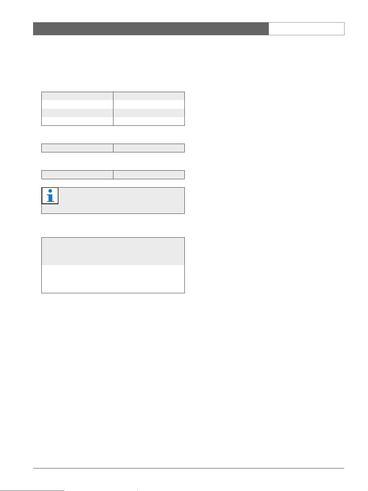
Conversion tables
Length, mass and temperature are in SI units. Refer to
the data below to change SI units to imperial units.
table 1: Conversion of units of length
1 in = 25.4 mm 1 mm = 0.03937 in
1 in = 2.54 cm 1 cm = 0.3937 in
1 ft = 0.3048 m 1 m = 3.281 ft
1 mi = 1.609 km 1 km = 0.622 mi
table 2: Conversion of units of mass
1 lb = 0.4536 kg 1 kg = 2.2046 lb
table 3: Conversion of units of pressure
1 psi = 68.95 hPa 1 hPa = 0.0145 psi
Note
1 hPa = 1 mbar.
table 4: Conversion of units of temperature
9
---
°F
°C
°C 32+⋅=
5
5
---
°F 32–()⋅=
9
Bosch Security Systems | 2007-08 | 9922 141 50672
Page 7

Plena Loop Amplifier | Installation and User Instructions | Table of contents en | 7
Table of contents
Important safeguards ...................................................................................................................................................3
Acknowledgements.......................................................................................................................................................4
About this manual .........................................................................................................................................................5
Table of contents ...........................................................................................................................................................7
1. System overview ...........................................................................................................................................................9
1.1 Loop amplifier ...........................................................................................................................................................................9
1.2 Induction loop systems ..........................................................................................................................................................9
1.2.1 Introduction .........................................................................................................................................................................9
1.2.2 Principle ...............................................................................................................................................................................9
1.2.3 Benefits ............................................................................................................................................................................. 10
1.3 Plena .......................................................................................................................................................................................10
1.4 Block diagram .......................................................................................................................................................................10
1.5 Supervision ............................................................................................................................................................................ 10
1.6 Quadrature system ..............................................................................................................................................................10
1.7 Controls, connectors and indicators ...............................................................................................................................12
1.7.1 Front view ......................................................................................................................................................................... 12
1.7.2 Rear view .......................................................................................................................................................................... 12
2. Design and planning ................................................................................................................................................. 13
2.1 Introduction ............................................................................................................................................................................13
2.2 System types ......................................................................................................................................................................... 13
2.2.1 Simple system ................................................................................................................................................................. 13
2.2.2 Quadrature systems ....................................................................................................................................................... 13
2.2.3 Expanded quadrature systems ....................................................................................................................................15
2.2.4 Low-spill system ..............................................................................................................................................................15
2.3 Induction loops ..................................................................................................................................................................... 16
2.3.1 Introduction ...................................................................................................................................................................... 16
2.3.2 Position ............................................................................................................................................................................. 16
2.3.3 Wire diameter .................................................................................................................................................................. 16
2.3.4 Magnetic field strength .................................................................................................................................................. 16
2.3.5 Connection ....................................................................................................................................................................... 16
2.3.6 Configuration ................................................................................................................................................................... 16
2.4 Potential problems ...............................................................................................................................................................18
2.4.1 Metal loss .........................................................................................................................................................................18
2.4.2 Overspill ............................................................................................................................................................................ 18
2.4.3 Earth loops .......................................................................................................................................................................18
3. Installation ................................................................................................................................................................... 19
4. External connections ................................................................................................................................................ 21
4.1 Induction loops ..................................................................................................................................................................... 21
4.2 Audio inputs .......................................................................................................................................................................... 21
4.3 Priority input ........................................................................................................................................................................... 22
4.4 Fault output ............................................................................................................................................................................ 23
4.5 Line output .............................................................................................................................................................................23
4.6 Power supply ......................................................................................................................................................................... 23
4.7 Slave to Master ..................................................................................................................................................................... 25
4.8 Slave to slave ........................................................................................................................................................................ 25
5. Configuration .............................................................................................................................................................. 27
Bosch Security Systems | 2007-08 | 9922 141 50672en
Page 8

Plena Loop Amplifier | Installation and User Instructions | Table of contents en | 8
5.1 Master and slaves ................................................................................................................................................................ 27
5.2 Electric current ...................................................................................................................................................................... 27
5.2.1 Master induction loops ..................................................................................................................................................27
5.2.2 Slave induction loops .................................................................................................................................................... 28
5.2.3 Bracket .............................................................................................................................................................................. 28
5.3 Metal loss compensation ....................................................................................................................................................28
5.4 Supervision ............................................................................................................................................................................ 29
5.5 Fault contact .......................................................................................................................................................................... 29
5.6 Priority input ........................................................................................................................................................................... 29
5.7 AGC/Limiter ..........................................................................................................................................................................29
5.7.1 Introduction ...................................................................................................................................................................... 29
5.7.2 Switch on and off ........................................................................................................................................................... 29
5.7.3 Range ................................................................................................................................................................................ 30
5.8 Frequency range ................................................................................................................................................................... 30
5.9 Audio inputs .......................................................................................................................................................................... 30
5.9.1 Sensitivity ......................................................................................................................................................................... 30
5.9.2 Phantom power ............................................................................................................................................................... 30
5.9.3 Voice activation ...............................................................................................................................................................31
6. Operation ..................................................................................................................................................................... 33
6.1 Switch on ............................................................................................................................................................................... 33
6.2 Switch off ............................................................................................................................................................................... 33
6.3 Change volume .....................................................................................................................................................................33
6.4 Change tone .......................................................................................................................................................................... 34
6.5 Condition LEDs ....................................................................................................................................................................34
Bosch Security Systems | 2007-08 | 9922 141 50672en
Page 9
Plena Loop Amplifier | Installation and User Instructions | System overview en | 9
1 System overview
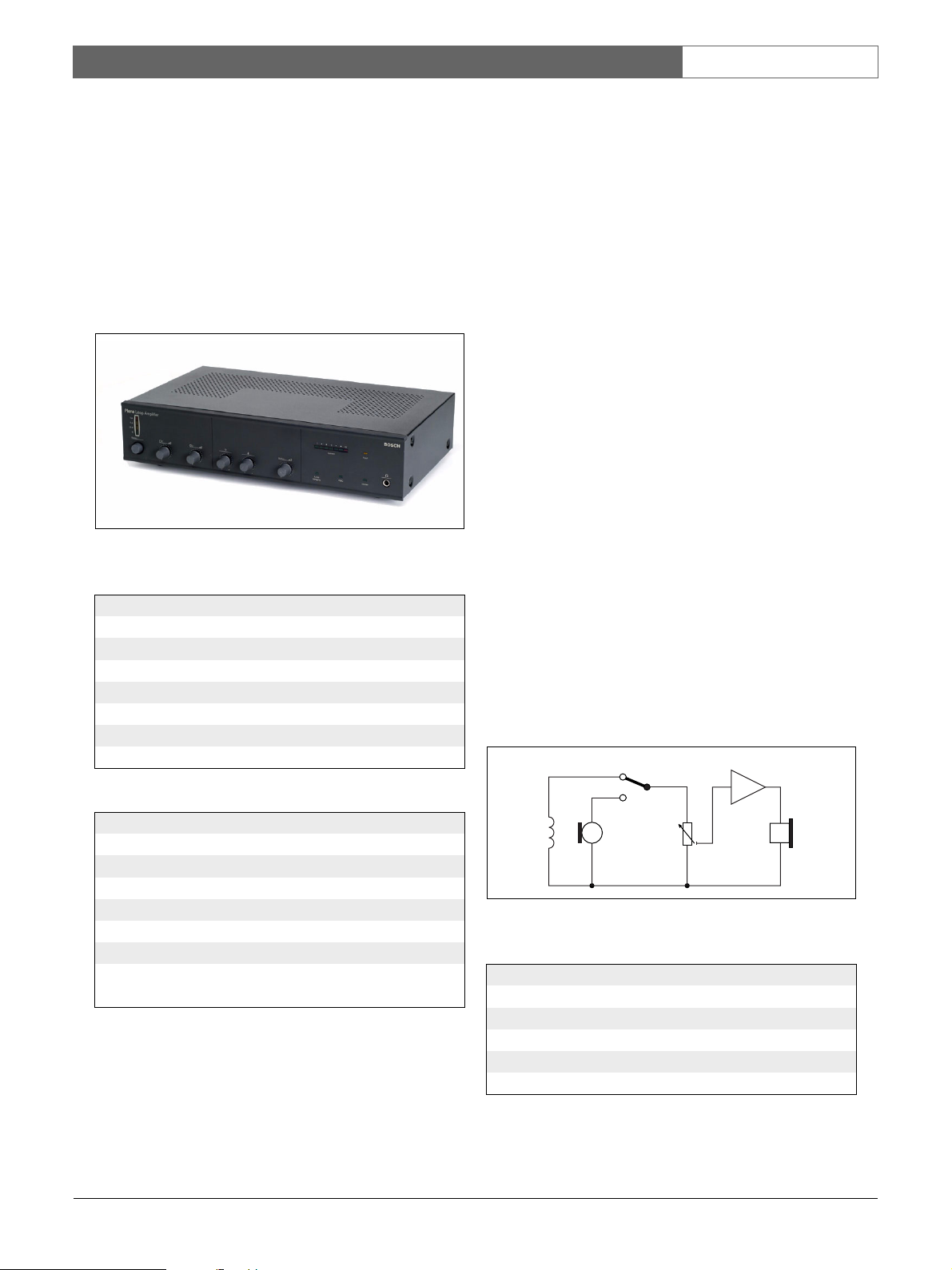
1.1 Loop amplifier
The PLN-1LA10 Plena Loop Amplifier has been
designed as a very high-quality amplifier for medium to
large size induction loop systems. Ease of installation
and use have been major factors in the design,
combined with optimized performance.
figure 1.1: Plena Loop Amplifier
table 1.1: Performance
Frequency response:
60 Hz to 10 kHz (+1/-3 dB, @ -10 dB @ rated output
Distortion:
< 1% @ rated output, 1 kHz
Bass control:
-8/+8 dB @ 100 Hz
Treble control:
-8/+8 dB @ 10 kHz
1.2 Induction loop systems
1.2.1 Introduction
An induction loop system consists of a looped wire that
is installed along the walls of a room and a loop
amplifier.
1.2.2 Principle
The loop amplifier changes incoming audio signals in
an alternating electric current that is sent through the
induction loop. The strength and frequency of the
electric current varies with the tone and the amplitude
of the incoming audio signal and generates an
alternating magnetic field inside the induction loop.
People with assistive listening devices who are located
inside the induction loop, can put their assistive listening
devices in the T or MT mode to listen to the audio
signals.
In the T or MT mode, a little coil is activated (T stands
for ‘tele-coil’). The coil receives the alternating magnetic
field and changes it into an alternating voltage, which
the assistive listening devices change into an audio
signal. This audio signal is not entirely the same as the
incoming audio signal of the loop amplifier, because the
assistive listening devices also compensate for individual
hearing disabilities (for example, signal strength and
frequency range).
T/MT
4
table 1.2: Certifications and approvals
EMC emission:
acc. to EN55103-1
EMC immunity:
acc. to EN55103-2
Safety:
acc. to EN60065
Induction loop systems:
acc. to EN60118-4
acc. to IEC118-4
Bosch Security Systems | 2007-08 | 9922 141 50672en
12 3 5
figure 1.2: Assistive listening device
table 1.3: Assistive listening device
No. Description
1 Tele-coil
2 Microphone
3 Gain control
4 Amplifier
5 Earphone
Page 10

Plena Loop Amplifier | Installation and User Instructions | System overview en | 10
1.2. 3 Benefit s
Ambient noise prevents hard-of-hearing people from
listening to a specific sound in a room. The ambient
noise can result from other people in the room,
equipment, but also from the acoustics. Depending on
the acoustics of the room, hard-of-hearing people
already find the reflected noise a strain when the
distance between them and the speaker is more than
2 m. The induction loop, to which the hard-of-hearing
people can listen with their assistive listening devices,
virtually reduces the distance to the speaker. Their
distance to the speaker seems equal to the distance
between the speaker and the microphone.
1.3 Plena
The Plena Loop Amplifier is part of the Plena product
range. Plena provides public address solutions for places
where people gather to work, worship, trade or simply
enjoy themselves. It is a family of system elements that
are combined to create public address systems tailored
for virtually any application. The range includes mixer,
pre, system and power amplifiers, a source unit, digital
message manager, feedback suppressor, conventional
and PC call stations, an ‘All-in-One’ system and a voice
alarm system. Each element is designed to complement
all others thanks to matched acoustical, electrical and
mechanical specifications.
1.4 Block diagram
Refer to figure 1.4 for a block diagram of the Plena
Loop Amplifier.
1.5 Supervision
All vital functions of the loop amplifier are supervised.
The loop amplifier checks its internal power amplifier,
the integrity of the connected induction loop and the
priority input with a pilot tone. When a supervised
function fails, a LED on the front panel of the loop
amplifier is lit and the fault contact is de-energized.
1.6 Quadrature system
One of the key features of the Plena Loop Amplifier is
that it can be used in quadrature systems. In a
quadrature system, an even number of Plena Loop
Amplifiers work together to create a magnetic field that
has the same strength throughout the whole covered
area and drops rapidly to zero beyond the borders of
the covered area. This is achieved by introducing a
phase difference of 90° in the electric current that flows
through two adjacent induction loops.
Bosch Security Systems | 2007-08 | 9922 141 50672en
Page 11
Plena Loop Amplifier | Installation and User Instructions | System overview en | 11
1 2
0dB
-6 dB
-20 dB
Power
1
0
2 Master
0
_
_
+
+
0
11 8 7 6 5 410 9
Metal loss
compensation
AGC
Master In
AGC
Limiter
2425
Slave Out
VU LED
PRE Amp. POST Amp.
Master Slave
Priority input
5K 10K
231422
Line Out
0º
90º
12
0
100 V
Vox Mix On Off
Fault
Supervision
NOCNC
On Off
Phantom Phantom
Mic Line On Off
1510
Current
Loop
Integrity
Mic Line
AGC Limiter
Line fuse: 230V 3A
Out Com
3
Fault
181712 15 1613
230V115V
Apparatus delivered
Connected for 230V
115V 6 A
Loop
192021
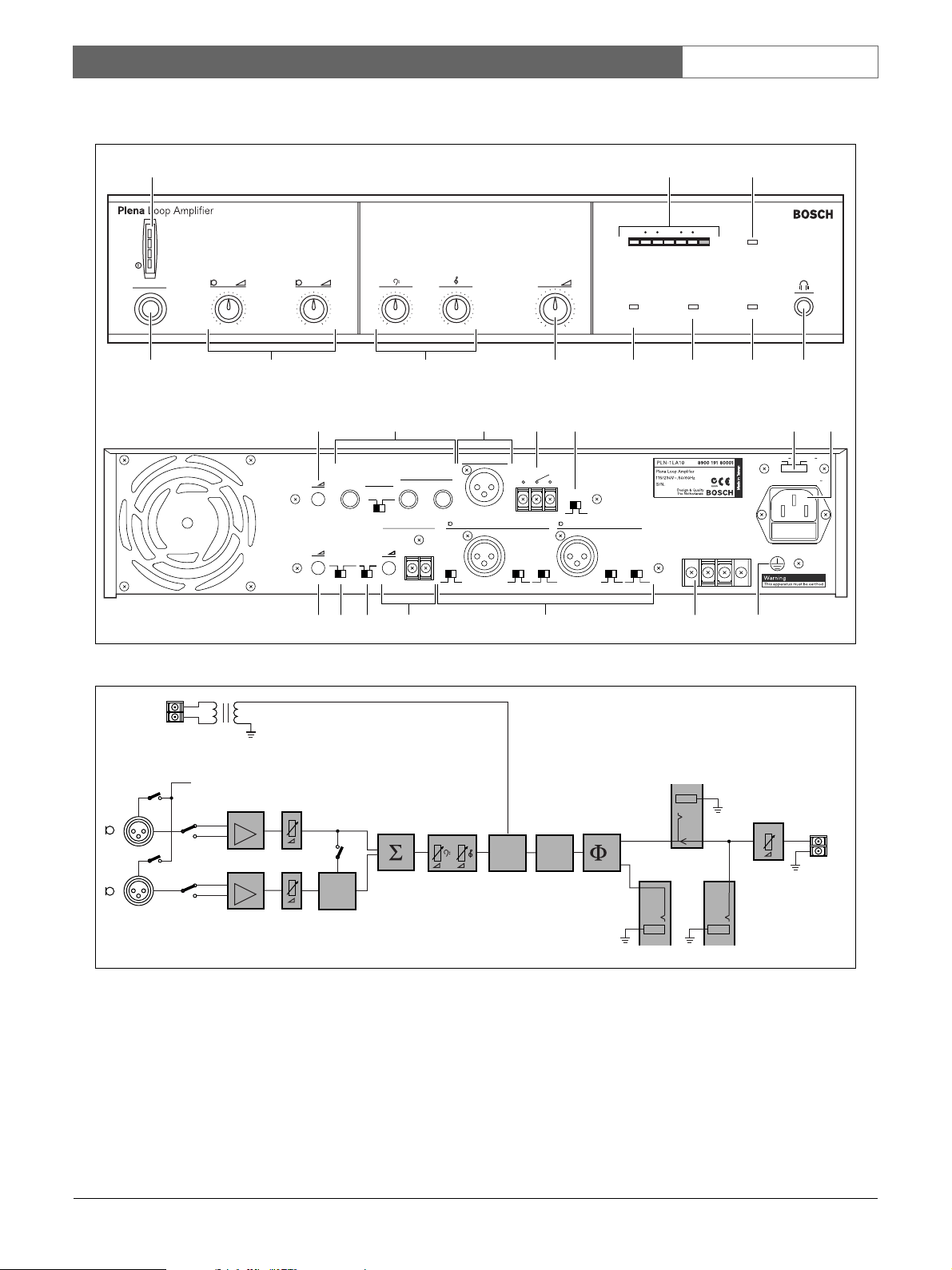
figure 1.3: Front and rear views
Priority
100 V
input
0
Phantom
Bal. input
Mic
1
Line
Bal. input
Mic
2
Line
figure 1.4: Block diagram
Vox Mix
Mute
Tone
Priority
control
Limiter
0º
90º
Master in
Slave out
90º 0º
Master
Out
Com
Bosch Security Systems | 2007-08 | 9922 141 50672en
Page 12

Plena Loop Amplifier | Installation and User Instructions | System overview en | 12
1.7 Controls, connectors and
indicators
1.7.1 Front view
The front of the loop amplifier (refer to figure 1.3)
contains:
1 Power LED/VU Meter - A combined power LED
and VU meter. The green power LED comes on
when the loop amplifier is switched on. The VU
meter shows the master VU level: 0 dB (red), -6 dB,
-20 dB (yellow).
2 Electric current meter - Show the electric
current through the induction loop.
3 Fault LED - Comes on when a supervised function
of the loop amplifier fails (refer to section 6.5).
4 Headphones socket - Connects headphones to
the loop amplifier.
5 Limiter LED - Comes on when the limiter is active
(refer to section 6.5).
6 AGC LED - Comes on when the automatic gain
control (AGC) is active (refer to section 6.5).
7 Loop integrity LED - Comes on when the
induction loop is intact (refer to section 6.5).
8 Master volume control - Sets the maximum
electric current that flows through the induction loop
(refer to section 5.2).
9 Tone c o ntro l s - Controls the high and low tones of
the audio signal on the induction loop (refer to
section 6.4).
10 Input volume controls - Control the volume of
audio input 1 and audio input 2 (refer to section 6.3).
11 On/off switch - Switches the loop amplifier on and
off (refer to section 6.1 and section 6.2).
1.7.2 Rear view
The rear of the loop amplifier (refer to figure 1.3)
contains:
12 Metal loss compensation control - Controls the
metal loss compensation (refer to section 5.3).
13 Master/slave sockets - Connect master and slaves
to the loop amplifier (refer to section 4.7).
14 Line output - Connects an external recording
device to the loop amplifier (refer to section 4.5).
15 Fault output - Sends the condition of the loop
amplifier to other equipment (refer to section 4.4).
16 Supervision switch - Switches supervision of the
priority input on and off (refer to section 5.4).
17 Voltage selector - Selects the voltage on which the
loop amplifier must operate (refer to section 4.6).
18 Power inlet - Connects the loop amplifier to the
mains power supply with a power cable (refer to
section 4.6).
19 Ground screw - Connects the loop amplifier to
ground.
20 Induction loop output - Connects the induction
loop to the loop amplifier (refer to section 4.1).
21 Audio inputs - Connects the loop amplifier to
external audio inputs (refer to section 4.2).
22 Priority input - Connect the loop amplifier to
systems that can override the audio signal on the
induction loop (refer to section 4.3). For example, a
Plena Voice Alarm System or a Praesideo system.
23 Frequency range switch - Select the frequency
range of the audio signal on the induction loop (refer
to section 5.8).
24 AGC/Limiter switch - Selects the automatic gain
control (AGC) or the limiter (refer to section 5.7.2).
25 AGC range control - Controls the range of the
automatic gain control (see section 5.7.3).
Bosch Security Systems | 2007-08 | 9922 141 50672en
Page 13

Plena Loop Amplifier | Installation and User Instructions | Design and planning en | 13
2 Design and planning
2.1 Introduction
We advise you to contact the local association of
hard-of-hearing people to make sure that the induction
loop system will be satisfactory in every way.
2.2 System types
2.2.1 Simple system
A simple induction loop system consists of a (master)
loop amplifier with one or more induction loops (refer
to figure 2.1 and figure 2.2).
When you connect more than one induction loop to a
(master) loop amplifier, make sure that the induction
loops are of the same size (refer to figure 2.2).
M
figure 2.2: Simple system, multiple loops
M
figure 2.1: Simple system, single loop
2.2.2 Quadrature systems
2.2.2.1 Introduction
One of the key features of the Plena Loop Amplifier is
that it can be used in quadrature systems. In a
quadrature system, an even number of Plena Loop
Amplifiers work together to make a magnetic field that
has the same strength throughout the whole covered
area drops fast to zero beyond the borders of the
covered area.
Bosch Security Systems | 2007-08 | 9922 141 50672en
Page 14

Plena Loop Amplifier | Installation and User Instructions | Design and planning en | 14
2.2.2.2 Simple quadrature system
A simple quadrature system consists of (refer to
figure 2.3):
• A master loop amplifier (M) with one induction loop.
• A slave loop amplifier (S) with one induction loop.
Note
Although it is not required, the sizes of the
master and slave induction loops are typically
the same.
0°
M
To cover larger areas, create a basic system with
multiple induction loops (refer to figure 2.4 for an
example). Such a system consists of:
• A master loop amplifier (M) with multiple induction
loops. All master induction loops must have the
same size.
• A slave loop amplifier (S) with multiple induction
loops. All slave induction loops must have the same
size.
Note
Although it is not required, the sizes of the
master and slave induction loops are typically
the same.
0°
90°
figure 2.3: Simple system, single loops
S
M
90°
0°
90°
figure 2.4: Simple system, multiple loops
S
Bosch Security Systems | 2007-08 | 9922 141 50672en
Page 15

Plena Loop Amplifier | Installation and User Instructions | Design and planning en | 15
2.2.3 Expanded quadrature systems
To cover very large areas, create an expanded
quadrature system (refer to figure 2.5 for an example).
Such a system consists of:
• A master loop amplifier (M) with one or more
induction loops. All master induction loops must
have the same size.
• An odd number of slave amplifiers (S1, S2, S3, etc.)
with one or more induction loops. All slave
induction loops must have the same size.
Note
Although it is not required, the sizes of the
master and slave induction loops are typically
the same.
0°
2.2.4 Low-spill system
A special type of quadrature system is the low-spill
system (refer to figure 2.6 for an example). A low-spill
system makes sure that the magnetic field strength drops
even more rapid to zero beyond the borders of the
covered area. Such a system consists of:
• A master loop amplifier (M) with one or more
induction loops. All master induction loops must
have the same size.
• An odd number of slave amplifiers (S1 in this
example) with one or more induction loops. All slave
induction loops must have the same size.
• Two slave amplifier (S2 and S3 in this example) with
one induction loop. The width of the induction loops
must be between 50 and 66% of the width of the
master induction loops.
0°
50-66%W
S2
90°
0°
M
figure 2.5: Expanded system (example)
90°
S1
S3
S2
90°
0°
M
figure 2.6: Low-spill system (example)
90°
W
W
50-66%W
S1
S3
Bosch Security Systems | 2007-08 | 9922 141 50672en
Page 16

Plena Loop Amplifier | Installation and User Instructions | Design and planning en | 16
2.3 Induction loops
2.3.1 Introduction
When you make an induction loop, you must take a
number of parameters into consideration. However,
sometimes there are special situations, which make the
design and planning of the induction loop even more
important. A number of potential problems and
solutions will be discussed later.
2.3.2 Position
For the best audio quality and the smallest variation in
the magnetic field strength, the distance between the
induction loop and the listening plane must be between
12 and 15% of the width of the room (refer to
figure 2.7).
H
Loop
12..15% W 12..15% W
Loop
W
figure 2.7: Position
For example, in a room with a width (W) of 10 m, the
induction loop should be installed 0 to 0.4 m below or
2.4 to 2.8 m above the floor for the best audio quality
and the smallest variation in the magnetic field strength.
Typically, you will install the induction loop in the floor
or in the ceiling of a room. When the distance between
the floor and the induction loop is too small (less than
8% of the width) or too large (more than 20% of the
width), refer to figure 2.8. The figure 2.8 shows the extra
power that the loop amplifier needs to make the correct
magnetic field. The numbers next to the curves show
the distance from the floor to the induction loop in % of
the width (W) of the room.
L
2.3.3 Wire diameter
For the best audio quality, the DC (direct current)
resistance of the induction loop must be between 1 and
3 Ω. The DC resistance depends on the wire diameter
and the wire length. Do as follows:
1 Calculate the wire length. The wire length depends
on the size of the induction loop.
2 Use figure 2.9 to get the allowed wire diameter.
For example, in a rectangular room with a width (W) of
10 m and a length (L) of 30 m, the wire length is 80 m.
According to figure 2.9, the wire diameter must be
between 0.77 and 1.34 mm. Thus, you can use AWG 20
wire or a wire with a standard diameter of 1.00 mm.
2.3.4 Magnetic field strength
For the best audio quality, the vertical component of the
magnetic field must be 100 mA/m ± 3 dB at 1.2 m
above the floor in the area that is surrounded by an
induction loop. The strength of the magnetic field
depends on the electric current through the induction
loop. Peaks in the strength of the magnetic field must be
less than 400 mA/m at 1.2 m above the floor in the area
that is surrounded by the induction loop.
2.3.5 Connection
Refer to section 4.1 for instructions that tell you how to
connect an induction loop to the loop amplifier.
2.3.6 Configuration
Refer to section 5.2 for instructions that tell you how to
configure the electric current through the induction
loop.
Bosch Security Systems | 2007-08 | 9922 141 50672en
Page 17

Plena Loop Amplifier | Installation and User Instructions | Design and planning en | 17
3
2
1
0
-1
-2
-3
-4
-5
-6
-7
-8
-9
power (dB)
-10
-11
-12
-13
-14
-15
-16
-17
-18
-19
0
10
20
30
40
50
60
70
80
90
10 0
10 20 30 40 50 60 70 80 90 100
figure 2.8: Extra power vs. the width of the room
width (%)
3.00
2.75
2.50
2.25
2.00
1.75
1.50
1.25
wire diameter (mm)
1.00
AWG 20
0.75
0.50
0.25
0.00
0 253050 76 90 100 135 150 200 250 300 350
34
wire length (m)
figure 2.9: Wire diameter vs. the wire length (copper wires)
303
Bosch Security Systems | 2007-08 | 9922 141 50672en
Page 18

Plena Loop Amplifier | Installation and User Instructions | Design and planning en | 18
2.4 Potential problems
2.4.1 Metal loss
New buildings often contain a large amount of metal
(for example, meshes in concrete floors and ceilings).
The metal will have an effect on the high frequencies of
the signal. You can adjust the tone of the audio signal on
the induction loops with the Metal loss compensation
control on the rear of the loop amplifier (refer to
section 5.3). The metal loss compensation is a variable,
signal dependent addition of high frequencies.
2.4.2 Overspill
The larger the induction loops, the more overspill.
When there is overspill, people outside the room with
the induction loop system can overhear the audio signal
on the induction loop. Overspill can also cause
interference on other induction loop systems in the
same building.
When you design a quadrature system (refer to
section 2.2.2 and section 2.2.3) or a low-spill system
(refer to section 2.2.4), you can avoid large induction
loops and thus avoid the potential problem of overspill.
2.4.3 Earth loops
Earth loops can cause interference on the induction loop
system. You can avoid earth loops when you connect
the shielding of cables only to one device.
Bosch Security Systems | 2007-08 | 9922 141 50672en
Page 19

Plena Loop Amplifier | Installation and User Instructions | Installation en | 19
3 Installation
The loop amplifier is sent to you in a box. Refer to
table 3.1 for the contents of the box.
Note
Always compare the contents of a shipment
with the descriptions on the shipment
documents.
table 3.1: Box
Description Quantity
Loop amplifier 1 x
Important Safety Instructions 1 x
Installation & User Instructions 1 x
Power cable 1 x
19” rack system brackets 2 x
Cover bracket 1 x
XLR cable 1 x
Make sure that there is a free space of at least 100 mm
on both sides of the loop amplifier for ventilation. The
loop amplifier has a regulated internal fan, which keeps
the temperature of the electronics within the safe range.
table 3.2: Physical characteristics
Dimensions (h x w x d):
94 x 430 x 320 mm (19” wide, 2U high)
Weight:
11. 6 k g
table 3.3: Environmental conditions
Operating temperature:
+5 to +45 °C
Storage temperature:
-25 to +55 °C
Relative humidity:
< 95%
Caution
Do not unpack the box until you install and
connect the loop amplifier.
Install the loop amplifier in a 19-inch rack system or on
a flat surface (refer to figure 3.1).
0
dB
-6
dB
2
0
dB
Po
w
e
r
1
2
+
1
5
1
0
Cu
r
Ma
r
en
s
t
t
e
r
+
F
a
ul
t
Lo
o
p
Int
e
g
r
i
t
y
A
G
C
L
i
m
i
t
er
figure 3.1: Installation
Bosch Security Systems | 2007-08 | 9922 141 50672en
Page 20

Plena Loop Amplifier | Installation and User Instructions | Installation en | 20
Intentionally left blank.
Bosch Security Systems | 2007-08 | 9922 141 50672en
Page 21

Plena Loop Amplifier | Installation and User Instructions | External Connections en | 21
4 External connections
4.1 Induction loops
Connect the induction loops to the rear of the loop
amplifier (refer to figure 4.1). Always twist wires that run
parallel and close to each other to avoid additional and
undesired inductions.
M
a
s
t
e
r
I
n
L
i
n
Sl
e
av
O
u
e
t
O
u
t
0
º
M
a
st
er
i
n
S
l
M
9
a
v
0
e
e
t
º
a
o
l
u
l
t
c
o
om
s
s
p
e
n
s
a
t
i
on
F
a
u
l
t
P
ri
o
r
i
t
y
i
n
p
ut
S
u
p
e
rv
i
si
1
1
o
n
N
O
C
AGC
Li
m
i
t
e
r
5
K
1
0
K
1
00
V
0
V
L
i
n
e
fuse: 23
0
V3A
115V 6A
L
oop
Out
Com
figure 4.1: Induction loop, connection
table 4.1: Induction loop, details
Number of connections:
1x screw terminal
Location:
Rear side
Current:
max. 10 A peak, max. 6 A continuous
Induction loop DC resistance:
0.5 to 3 Ω
Induction loop area:
max. 600m2 @ 100 mA
RMS
/m
o
x
M
i
x
115V
N
C
230V
O
n
O
f
f
A
2
2
p
p
ara
t
u
s
C
d
o
e
n
l
i
n
ve
e
c
r
ed
t
e
df
o
r
2
3
0
P
h
a
O
n
V
n
t
om
L
i
n
e
f
u
se
:
2
3
0
V
3
P
A
h
a
n
1
t
o
1
m
5
V6
O
f
f
A
M
i
c
L
in
e
L
o
o
p
O
u
tC
o
O
m
n
O
f
f
M
i
c
L
i
n
e
4.2 Audio inputs
You can connect audio sources to the audio inputs of
the loop amplifier. For example, you can connect a
power amplifier and a microphone (refer to figure 4.2).
PLN-1LA10
Loop Amplifier
M
a
s
t
e
r
I
n
L
i
n
S
e
l
a
O
v
u
e
t
O
u
t
0
º
M
a
s
te
r
i
n
S
Me
l
9
a
v
0
e
ta
º
o
l
u
l
t
c
o
o
s
m
s
p
e
n
s
a
t
i
o
n
F
a
u
l
t
P
r
i
o
r
i
t
y
i
n
pu
t
S
u
p
e
r
v
i
s
i
1
1
on
N
O
C
N
C
P
h
anto
m
O
n
O
ff
M
i
c
D
+
2
3
l
in
e
o
u
t
O
n
O
ff
2
2
P
h
a
n
t
o
m
Lin
e
O
n
O
f
f
M
ic
L
i
ne
l
ine
o
1
0
0
V
7
0
V
0
0
8
L
i
n
e
fu
s
e
:
2
3
0
V
3
1
1
5
V6
L
o
o
p
O
u
tC
o
m
Phant
om Phant
On
Off
u
t
2
4
V
DCI
N
+
L
i
n
e
fu
s
e
2
5
0
V
T1
W
a
r
n
i
n
g
T
h
i
s
a
p
p
a
r
a
tu
s
m
u
s
t
b
e
1
15V
2
3
0
V
A
p
p
a
r
a
t
u
s
C
d
o
e
n
l
i
n
v
e
e
c
r
e
t
e
d
d
f
o
r
2
3
0
V
A
A
2
2
Mi
om
c
On Off
PLN-1P120
Power Amplifier
2
3
0
V
2
4
0
V
-
A
A
p
pa
r
a
t
u
s
c
d
o
e
n
l
i
n
ve
e
c
r
e
t
ed
d
e
a
f
o
rt
r
h
e
2
d
3
0
V
-
A
G
C
L
i
m
i
t
e
r
5
K
1
0
K
1
0
0
V
0
Vo
x
M
i
x
1
1
Phantom
Vox
Mix
On Off
G
N
1
+
G
N
D
1
G
N
1
2
D
0
-
0
+
V
1
3
0
2
V
3
figure 4.2: Audio inputs, connection
table 4.2: Audio inputs, details
Number of connections:
2x XLR sockets
Location:
Rear side
Sensitivity:
Switchable, 1 mV/1 V
Impedance:
>1 kΩ
Dynamic range:
10 0 d B
Signal-to-noise ratio:
63 dB @ max. volume
75 dB @ min. volume/mute
Headroom:
25 dB
Phantom power:
Switchable, 16 V
VOX functionality:
Switchable, input 1 mutes input 2
Bosch Security Systems | 2007-08 | 9922 141 50672en
Page 22

Plena Loop Amplifier | Installation and User Instructions | External Connections en | 22
4.3 Priority input
You can connect other devices or systems to the priority
input. The priority input has a higher priority than
audio input 1 and audio input 2. When the priority
input receives a signal, the loop amplifier replaces the
signal on the connected induction loops with the signal
of the priority input.
PLN-1LA10
Loop Amplifier
M
as
t
e
r
In
L
i
n
S
e
l
av
O
u
e
t
O
u
t
0
º
M
asteri
n
S
l
M
9
a
v
0
e
e
t
º
a
ou
l
l
t
c
o
o
s
m
s
p
e
n
s
a
t
i
o
n
F
au
l
t
P
ri
o
r
i
t
y
i
n
pu
t
S
u
pe
r
v
i
s
i
1
1
o
n
N
O
C
A
G
C
Lim
it
er
5
K
1
0
K
100
V
0
Vo
x
M
ix
In
tB
oost
1 Channel
e
r
Ex
tB
BGM/
ooster
10
Z1
0
10
Z2
10
Z3
1
0
Z4
2 Channel
C
a
l
l
N
.
C
BGM/
.
/
Spare
Sp
A
0
V
0
V
0
0
V
0
0
V
0
E
B
o
D
are
C
all
B
10
0
V
0
10
0
V
0
10
0
V
I
n
t
B
oos
1C
t
e
r
ha
nn
E
x
el
t
B
B
o
o
G
ste
M
2
/
r
C
C
a
ha
l
l
n
n
e
N
l
.
C
B
.
/
G
S
p
M
a
/
r
S
e
p
a
A
r
e
C
a
l
l
1
0
0
Z
V
1
B
O
v
e
r
r
i
d
e
/
T
0
r
i
g
g
e
r
O
u
t
p
1
u
0
Z
t
0
2
1
V
0
0
V
2
T
4
r
i
g
V
g
e
r
i
0
n
p
u
Z
t
0
/
1
2
Z
4
E
1
V
m
D
e
C
r
ge
o
u
n
1
t
c
0
Z
1
y
0
3
1
V
0
0
V
2
3
Z
2
0
4
Z
N
2
0
C
5
2
4
V
B
6
C
u
O
1
s
D
0
M
Z
i
N
n
C
0
4
C
1
e
V
o
0
s
Z
E
u
s
0
t
3
M
V
1
N
NO
G
O
2
3
0
Z
N
3
0
C
C
O
4
M
Z
4
5
1
1
C
0
0
V
k
O
O
Z
0
X
M
V
5
1
6
1
0
0
k
F
S
0
w
a
V
i
u
t
c
N
l
h
t
O
1
Z
5
0
2
Z
4
0
N
C
3
1
0
4
Z
0
C
6
V
O
1
0
M
0
5
V
Z
C
6
a
l
NO
l
2
6
4
V
0
D
C
Z
o
0
x
u
5
t
t
C
N
C
al
T
l
R
1
o
0
s
t
0
e
V
r
I
n
0
C
I
n
2
4
V
s
G
t
a
t
1
i
o
1
2
0
n
4
0
V
V
V
o
l
Fo
u
NO
m
r
e
s
O
e
v
r
v
e
Z
r
0
6
r
i
d
e
T
R
1
0
G2
0
V
7
I
n
0
t
1
V
B
1
o
2
o
s
t
e
r
O
3
0
u
t
O
u
4
t
5
1
0
6
0
V
V
O
X
S
2
C
w
i
t
a
c
l
h
l
o
u
t
I
n
G
N
D
E
x
t
e
r
n
al
B
o
o
s
L
t
e
r
C
D
/T
u
n
e
r
R
A
U
X
P
C
figure 4.3: Priority input, connection
115V
N
C
230
V
O
n
O
f
f
A
2
2
p
p
a
r
a
tus
C
d
o
e
n
l
i
n
v
e
e
c
r
ed
t
e
d
f
or
2
3
0
P
h
a
nto
m
O
n
V
L
i
n
e
f
u
se
:
2
3
0
V
3
P
A
h
a
n
1
t
om
1
5
V
O
f
6
f
A
M
i
c
Lin
e
L
o
o
p
O
u
tC
o
O
m
n
O
f
f
M
i
c
L
i
n
e
Priority input
5K 10K
100V
0
Z1
Z2
LBB1990/00
Voice Alarm Controller
L
B
B
1
9
i
9
c
0
e
/0
o
n
08
l
y
P
l
e
n
a
V
9
o
0
i
M
c
01
S
eA
a
E
x
.
L
9
l
o
a
1
9
u
r
m
t
p
0
R
u
C
0
a
t
o
t
0
p
e
n
S
0
d
o
t
E
r
1
w
o
o
M
L
e
l
u
l
1
e
r
0
t
o
1
p
r
3
n
5
u
6
i
t
t
2
0
o
p
30
W
o
r
F
w
V
i
A
r
e
S
~
m
r
P
/
,
2
N
w
5
R
4
.
0
ar
0
m
/
W
6
e
o
0
U
d
H
S
p
e
z
u
g
p
r
ad
e
1
r
1
v
e
5
i
s
V
2
i
o
c
~
D
n
h
esi
o
g
p
n
e
O
T
&
2
h
r
L
Q
f
3
N
a
e
f
6
B
t
u
0
N
6
i
3
a
o
et
B
V
l
i
n
t
~
h
1
y
e
9
r
l
9
a
nd
4
s
MadeinChina
App
O
n
ar
at
u
s
C
de
o
n
l
n
i
v
e
e
c
U
r
t
e
e
S
d
O
d
B
f
f
f
o
r
2
3
I
0
m
V
p
~
e
d
an
c
C
e
F
al
i
i
r
b
e
r
m
a
O
t
an
i
o
n
n
'
sp
a
n
e
l
P
o
w
e
r
R
at
e
d
i
n
p
u
t
p
L
o
B
w
G
B
e
N
1
r
D
9
:
7
9
6
4
0
V
A
L
i
n
e
f
u
s
e
T
6
.
3
L
2
5
0
T
V
1
0
f
o
L
V
r
2
ox
2
5
3
0
0
V
V
f
A
o
r
C
S
1
1
p
5
e
V
e
c
A
h
C
M
R
f
i
i
l
e
c
t
e
m
/
P
L
r
o
h
i
n
t
a
e
e
n
to
C
m
o
n
p
t
r
ow
o
l
e
P
O
r
an
f
f
e
l
Vo
O
x
n
1
R
o
u
D
t
e
i
g
r
i
t
a
l
M
es
M
o
s
n
a
2
i
g
t
o
e
r
i
n
g
S
p
e
ak
e
r
W
a
r
n
i
n
g
T
h
i
s
a
p
p
a
r
a
t
u
sm
u
st
b
e
e
a
r
t
h
e
d
For example, you can connect a Plena Voice Alarm
System (refer to figure 4.3) to the priority input.
Caution
Install the safety bracket on the priority input to
make sure that it is not possible to touch the
priority input (refer to figure 4.4).
Priority input
1
AGC Limiter
5K
10K
10
0V
0
1
Vox
Mix
figure 4.4: Safety bracket
table 4.3: Priority input, details
Number of connections:
1x screw terminal
Location:
Rear side
Input sensitivity:
100 V, transformer-balanced
Signal-to-noise ratio:
63 dB @ max. volume
75 dB @ min. volume/mute
Headroom:
25 dB
Bosch Security Systems | 2007-08 | 9922 141 50672en
Page 23

Plena Loop Amplifier | Installation and User Instructions | External Connections en | 23
Line Out
Fault
1
NO
C
NC
90º
1
4.4 Fault output
With the fault output (refer to figure 4.5), you can send
the condition of the loop amplifier to external devices
(for example, sounders).
PLN-1LA10
Loop Amplifier
LineOut
Fault
Supervision
NOCNC
On Off
12
Phantom Phantom
0
Vox Mix On Off
Mic Line On Off
Mic Line
compensation
SlaveOut
MasterIn
VULED
0º 90º
PREAmp. POST Amp.
Metalloss
MasterSlave
Priorityinput
AGC
Limiter
5K 10K
100V
Fault
C
NC
NO
NC
COM
NO
figure 4.5: Fault output, relay
The fault output is an internal relay. By default, NC is
connected to COM. When a supervised function of the
loop amplifier fails, the relay connects NO to COM.
table 4.4: Fault output, details
Number of connections:
1x screw terminal
Location:
Rear side
Contacts:
Voltage-free, max. 100 V, 2 A
Signal-to-noise ratio:
63 dB @ max. volume
75 dB @ min. volume/mute
Headroom:
25 dB
Linefuse: 230V 3A
Loop
Out Com
230V115V
Apparatusdelivered
Connectedfor 230V
115V 6 A
4.5 Line output
You can connect a recording device (for example, a
tape deck) to the line output of the loop amplifier (refer
to figure 4.6).
PLN-1LA10
Loop Amplifier
M
a
s
t
e
r
In
L
i
n
Sl
eO
a
v
u
e
t
O
u
t
0
º
M
as
t
e
ri
n
S
l
M
9
av
0
e
eou
t
º
a
l
l
t
c
o
o
s
m
s
p
e
n
s
a
t
i
o
n
F
au
l
t
P
r
i
o
r
i
t
y
i
n
pu
t
S
u
pe
r
v
i
s
i
1
1
on
N
O
C
A
G
C
L
i
m
i
t
e
r
5
K1
0
K
1
0
0
V
0
V
o
x
M
i
x
11
5
N
V
C
2
30V
O
n
O
f
f
A
2
2
p
p
a
r
a
t
u
s
C
d
o
e
n
l
i
n
ve
e
c
r
e
t
e
d
df
o
r
2
3
0
V
P
h
an
to
m
L
i
n
e
fu
s
e
:
2
3
0
V3
P
A
h
O
a
n
n
1
t
o
1
m
5
V
O
ff
6
A
M
i
c
L
i
n
e
L
o
o
p
O
u
t
C
o
O
m
n
O
ff
M
i
c
L
i
n
e
figure 4.6: Line output, connection
table 4.5: Line output, details
Number of connections:
1x XLR plug
Location:
Rear side
Nominal level:
1V
Impedance:
200 Ω
4.6 Power supply
To connect the loop amplifier to a mains power supply
do as follows:
1 Set the voltage selector on the rear of the loop
amplifier to the correct position (refer to table 4.6).
table 4.6: Voltage selector
Power supply voltage Voltage selector
100 t o 120 V( AC) 115
220 to 240 V(AC) 230
Note
The PLN-1LA10 Loop Amplifier is delivered with
the voltage selector in the 230 position.
Bosch Security Systems | 2007-08 | 9922 141 50672en
Page 24

Plena Loop Amplifier | Installation and User Instructions | External Connections en | 24
Loop
A
ppa
r
a
tusd
el
i
ver
ed
Connect
edf
or2
3
0
V
Out
Com
230V
115
V
Li
ne
f
us
e
:2
3
0
V3
A
115
V6A
2 Make sure that the fuse holder in the rear of the loop
amplifier contains the correct fuse (refer to table 4.7).
table 4.7: Fuses
Voltage selector Fuse
115 10 AT
230 6.3AT
Note
The PLN-1LA10 Loop Amplifier is delivered with
a 6.3AT fuse.
3 Connect a locally approved power cable from the
loop amplifier to a power outlet (refer to figure 4.7).
M
as
t
e
r
I
n
L
i
ne
S
l
av
O
u
e
t
Out
0
º9
M
a
s
t
e
r
i
n
Sl
M
a
v
0
e
eou
ta
º
ll
t
c
o
o
s
m
s
p
e
n
s
a
t
i
o
n
F
a
u
l
t
P
r
i
o
r
i
t
y
i
n
p
u
t
S
u
p
e
r
v
i
sio
1
12
n
N
O
C
AG
C
L
i
m
i
t
e
r
5
K
1
0
K
1
0
0
V
0
Vo
x
M
ix
1
15
N
V
C
2
3
0
V
O
n
O
f
f
A
2
p
p
ar
a
t
u
s
C
de
o
n
l
i
n
v
e
er
c
ed
t
e
d
f
o
r
2
30
P
h
a
n
t
om
O
n
O
f
f
M
ic
L
V
L
i
n
e
f
u
s
e:
2
30
V
3
P
h
A
a
n
1
t
om
1
5
V
6
A
i
n
e
Lo
o
p
O
u
t
Com
O
n
O
f
f
M
i
c
L
i
n
e
PLN-1LA10
Loop Amplifier
figure 4.7: Power supply, connection
table 4.8: Power supply, details
Mains voltage:
230/115 V(AC), ±10%, 50/60 Hz
Power consumption:
max. 400 W
Mains inrush current:
max. 7 A @ 230 V(AC), max. 14 A @ 115 V(AC)
Signal-to-noise ratio:
63 dB @ max. volume
75 dB @ min. volume/mute
Headroom:
25 dB
Bosch Security Systems | 2007-08 | 9922 141 50672en
Page 25

Plena Loop Amplifier | Installation and User Instructions | External Connections en | 25
AGC
Lim
i
t
er
Line O
5K
10K
1
Prio
r
ity input
90º
1
AGC
eta
l
los
s
m
pensa
t
ion
L
i
m
i
t
e
r
Line
O
5K
10K
1
Pr
i
o
r
i
t
y
i
np
ut
90
º
1
AGC
eta
l
los
s
m
pens
at
ion
L
i
m
i
t
e
r
LineO
5K 10K
1
Pr
i
o
r
i
t
y
i
np
ut
90
º
1
AGC
eta
l
los
s
m
p
ensation
Limi
t
er
Line
O
5K
10K
1
Pr
i
o
rit
yinput
90
º
1
AGC
eta
l
los
s
m
pensati
on
Limi
t
er
LineO
5K 10K
1
Pr
i
o
rit
yinput
90
º
1
4.7 Slave to Master
Connect the 0° Slave Out socket or 90° Slave Out of the
master loop amplifier to the Master in socket of the slave
loop amplifier. For an example, refer to the connection
from Master to Slave 2 in figure 4.8 and the connection
from Master to Slave 1 in figure 4.8.
M
a
st
er
I
n
V
Li
ULE
ne
S
l
a
O
v
D
u
e
t
O
ut
0
º
P
R
E
A
mp
.
P
O
M
S
et
T
A
a
m
ll
p
compe
o
.
ss
n
sa
t
i
o
n
Mas
t
e
r
S
l
a
ve
P
r
i
o
r
i
t
y
i
nput
1
1
AG
C
L
i
m
i
t
e
r
5K
1
0K
1
0
0
V
0
Vox
M
i
x
Master In
VU LED
PRE Am
p
.
POST
Master
Slave
4.8 Slave to slave
Connect the 0° Slave Out socket of the slave loop
amplifier to the Master in socket of the next slave loop
amplifier. For an example, refer to the connections from
Slave 1 to Slave 3 and Slave 2 to Slave 4 in figure 4.8.
Master
F
au
l
t
S
uper
vi
s
i
o
n
NO
C
N
C
O
n
O
f
f
2
2
Ph
a
n
t
om
Ph
O
n
O
f
f
M
i
c
L
in
e
O
n
Slave Out
0º
Amp.
1
1
5
V
230V
A
p
parat
u
s
C
del
o
n
i
nectedfo
ver
e
d
r
23
0
V
Lin
efu
s
e
:
23
0
V
3
A
a
n
11
t
o
m
5V6A
L
o
o
p
O
u
t
C
om
O
f
f
M
i
cL
in
e
Master In
VU LED
P
R
EA
mp
.
P
OS
T
A
mp
.
M
a
s
t
e
r
Slave
Slave 2
M
a
s
t
e
r
I
n
L
V
i
U
n
S
e
L
l
Ou
a
E
ve
D
t
O
u
t
0º
P
R
E
A
mp
.
P
O
M
9
S
0
e
T
t
º
A
a
mp
l
l
c
o
.
o
s
m
s
p
e
n
s
a
t
i
o
n
F
a
u
lt
M
a
s
t
e
r
S
l
a
v
e
P
r
ior
i
t
y
i
n
p
u
t
S
u
p
e
r
v
i
s
i
1
1
on
N
O
C
A
G
C
L
i
m
ite
r
5K
1
0K
1
0
0
V
P
h
0
V
o
x
M
i
x
O
n
1
1
5V
N
C
23
0V
O
n
O
f
f
Ap
2
2
p
a
r
a
t
u
s
C
d
o
e
n
l
iv
n
e
e
c
r
e
t
e
d
d
fo
r
2
3
0
an
to
m
O
f
f
M
i
c
V
L
i
n
e
fu
s
e
:
2
3
0
V3
P
h
A
an
1
to
15
m
V
6
A
L
i
n
e
L
o
op
O
u
t
C
o
O
m
n
O
f
f
M
i
c
L
i
n
e
M
aster
I
n
V
U
L
ED
P
R
EA
mp
.
P
OS
T
A
mp
.
M
a
s
t
e
r
Slave
Slave 4
M
a
st
e
r
I
n
L
V
i
U
n
S
e
L
l
Ou
a
E
ve
D
t
O
u
t
0º
P
RE
A
mp
.
P
O
M
9
S
0
e
T
t
º
A
a
mp
l
l
c
o
.
o
s
m
s
p
e
n
s
a
t
i
o
n
F
a
u
lt
M
a
s
te
r
Sla
v
e
P
r
io
r
i
t
y
i
n
p
u
t
S
u
p
e
r
v
i
si
1
1
o
n
N
O
C
N
an
to
m
O
f
f
M
i
C
O
nO
2
2
c
L
i
n
eO
1
1
5
V
23
0V
f
f
Ap
p
a
r
a
t
u
s
C
d
o
e
n
l
ive
n
e
c
r
e
t
e
d
d
fo
r
2
3
0
V
L
i
n
e
fu
s
e
:
2
3
0
V
3
P
h
A
an
1
to
15
m
V
6
A
L
o
op
O
u
t
C
o
m
n
O
f
f
M
i
c
L
i
n
e
A
G
C
L
i
m
ite
r
5K
1
0K
1
0
0
V
P
h
0
V
o
x
M
i
x
O
n
figure 4.8: Master and slave loop amplifiers
Slave O
S
M
as
t
e
rIn
VU LED
Sla
u
t
0
º
ve Out
0º
P
R
EA
mp
.
P
OS
T
Amp
.
M
a
s
t
e
r
Slave
Slave 1
M
a
s
t
e
rI
n
L
V
i
U
n
e
S
L
l
Ou
a
E
v
D
e
t
O
u
t
0
º
PR
E
Am
p
.
PO
M
9
S
0
e
T
t
º
A
a
m
l
p.
l
c
o
o
s
m
s
p
e
n
s
a
t
io
n
F
au
l
t
M
a
s
t
e
r
Sla
v
e
P
r
i
or
i
t
y
i
n
p
u
t
S
u
p
e
r
v
is
i
1
1
o
n
N
O
C
A
G
C
L
i
m
i
t
e
r
5K
1
0K
1
0
0V
0
V
o
x
M
i
x
M
a
ster
I
n
V
U
S
l
ave O
u
t
0
º
LED
la
ve Out
0º
P
R
EA
mp
.
P
OS
T
Amp
.
M
a
s
t
e
r
Slave
1
1
5V
N
C
P
h
an
t
o
m
O
n
O
f
f
M
i
c
230
V
O
nO
f
f
A
2
2
p
p
a
r
a
t
u
s
C
d
on
e
li
n
v
e
e
c
r
e
t
e
d
d
fo
r
23
0
V
L
i
n
e
fu
s
e:
23
0
V3A
P
h
a
n
1
t
o
15
m
V6
A
L
i
n
e
L
oo
p
Ou
t
C
om
O
n
O
f
f
M
i
c
L
i
n
e
Slave 3
M
a
s
t
e
rI
n
L
V
i
U
n
S
e
L
l
Ou
a
E
v
D
e
t
O
u
t
0
º
PR
E
Am
p
.
PO
M
9
S
0
e
T
t
º
A
a
m
l
p.
l
c
o
o
s
m
s
p
e
n
s
a
t
io
n
Fau
l
t
M
a
s
t
e
r
Sla
v
e
P
r
i
or
i
t
y
i
n
p
u
t
S
u
p
e
r
v
is
i
1
1
on
N
O
C
A
G
C
L
i
m
i
t
e
r
5K
1
0K
1
0
0V
0
V
o
x
M
i
x
1
1
5V
N
C
P
h
an
t
o
m
O
n
O
f
f
M
i
c
230V
O
nO
f
f
Ap
2
2
p
a
r
a
t
u
s
C
d
on
e
l
i
n
v
e
e
c
r
e
t
e
d
d
fo
r
23
0
V
L
i
n
e
fu
s
e:
23
0
V3A
P
h
an
1
t
o
15
m
V6
A
L
i
n
e
L
oop
Ou
t
C
om
O
n
O
f
f
M
i
c
L
i
n
e
Bosch Security Systems | 2007-08 | 9922 141 50672en
Page 26

Plena Loop Amplifier | Installation and User Instructions | External Connections en | 26
Intentionally left blank.
Bosch Security Systems | 2007-08 | 9922 141 50672en
Page 27

Plena Loop Amplifier | Installation and User Instructions | Configuration en | 27
5 Configuration
5.1 Master and slaves
Set the Master in/Slave out switches on the rear of all
loop amplifiers (refer to figure 5.1) in the induction loop
system in the correct position.
•The Master/Slave switch of the master loop amplifier
must be in the Master position.
•The Master/Slave switch of all slave loop amplifiers
must be in the Slave position.
Master In
figure 5.1: Master/Slave switch
Note
Slave loop amplifier can only send the signal
that they receive from the master loop amplifier
to their induction loops. The audio inputs and
the priority input of the slave loop amplifiers are
disabled.
VU LED
PRE Amp. POST Amp.
Master Slave
Slave Out
0º 90º
5.2 Electric current
5.2.1 Master induction loops
Do as follows:
1 Connect a pink noise source to audio input 2 on the
rear of the master loop amplifier.
2 Connect the master loop amplifier to the mains
power supply with a power cable.
3Set the AGC/Limiter switch on the rear of the master
loop amplifier in the Limiter position.
4 Switch on the pink noise source.
5 Set the signal strength of the output signal of the pink
noise source to 0 dBV.
6 Switch on the master loop amplifier with the power
switch on the front.
7 Increase the volume of audio input 2 of the master
loop amplifier with its input volume control until the
Limiter LED on the front of the master loop amplifier
comes on.
8 Increase the electric current through the master
induction loops with the Master volume control on
the front of the master loop amplifier until the
magnetic field strength in each master induction
loop is 100 mA/m.
Note
Instead of a pink noise source, you can use a
sine wave of 1 kHz. Then, the magnetic field
strength must be 70 mA/m in each master
induction loop.
Bosch Security Systems | 2007-08 | 9922 141 50672en
9 Switch off the master loop amplifier with the power
switch on the front.
10 When the induction loop system contains slave loop
amplifiers, configure the electric current through the
slave induction loops (refer to section 5.2.2).
Page 28

Plena Loop Amplifier | Installation and User Instructions | Configuration en | 28
5.2.2 Slave induction loops
Do as follows:
11 Disconnect the master induction loops from the
master loop amplifier.
12 Connect the slave loop amplifier to the mains power
supply with a power cable.
13 Set the AGC/Limiter switch on the rear of the slave
loop amplifier in the Limiter position.
14 Switch on the master loop amplifier with the power
switch on the front of the master loop amplifier.
15 Switch on the slave loop amplifier with the power
switch on the front of the slave loop amplifier. When
the induction loop system contains more than one
slave loop amplifier, make sure that all other slave
loop amplifiers are off.
16 Increase the volume of audio input 2 of the slave
loop amplifier with its volume control until the
Limiter LED on the front of the slave loop amplifier
comes on.
17 Increase the electric current through the slave
induction loops with the Master volume control on
the front of the slave loop amplifier until the
magnetic field strength in each slave induction loop
is 100 mA/m (pink noise source) or 70 mA/m (sine
wave of 1 kHz).
18 Switch off the slave loop amplifier with the power
switch on the front of the slave loop amplifier.
19 Repeat the procedure for the other slave loop
amplifier in the induction loop system.
Note
Do not forget to re-connect all induction loops
after you have configured the electric current
through the induction loop of the last loop
amplifier.
5.2.3 Bracket
You can cover the front of the loop amplifier with a
bracket (refer to figure 5.2). When you cover the front,
you make sure that nobody can change the position of
the volume controls. Thus, you make sure that nobody
can change the electric current through the induction
loop that is connected to the loop amplifier.
0
dB
-6dB
-20dB
Power
1
2
+
1
5
1
0
Cu
r
M
r
e
a
n
s
t
t
e
r
+
F
a
ul
t
L
o
op
Int
e
g
r
i
t
y
A
G
C
L
i
m
i
t
e
r
figure 5.2: Cover bracket
5.3 Metal loss compensation
Do as follows:
1Turn the Metal loss compensation control on the
rear of the loop amplifier to the leftmost position.
2 Connect headphones to the headphones socket on
the front of the loop amplifier to listen to the audio
signal that is sent to the connected induction loops.
3 With the same headphones, listen to the audio signal
on the induction loops through an induction loop
receiver.
4Turn the Metal loss compensation control to adjust
the tone of the audio signal on the induction loops.
5 Repeat the procedure for the other loop amplifiers in
the induction loop system.
Bosch Security Systems | 2007-08 | 9922 141 50672en
Page 29

Plena Loop Amplifier | Installation and User Instructions | Configuration en | 29
5.4 Supervision
You can switch supervision (refer to section 1.5) on and
off with the Supervision switch. The Supervision switch
is on the rear of the loop amplifier (refer to figure 5.3).
• To switch on supervision, set the Supervision switch
in the ON position.
• To switch off supervision, set the Supervision switch
in the OFF position.
Fault
Supervision
NO
C
NC
On Off
figure 5.3: Supervision switch
5.5 Fault contact
You can configure the fault contact with the Supervision
switch (refer to section 5.4).
• If supervision is off, the internal relay is de-energized
(NO position).
• If supervision is on and the loop amplifier operates
correctly, the internal relay is energized
(NC position).
• If supervision is on and the loop amplifier does not
operate correctly, the internal relay is de-energized
(NO position).
5.7 AGC/Limiter
5.7.1 Introduction
Automatic gain control (AGC) keeps the level of the
audio signal on the connected induction loops constant.
The limiter makes sure that audio signals with a strength
of more than 0 dBV are not sent to the connected
induction loops.
5.7.2 Switch on and off
You can switch automatic gain control (AGC) on and
off with the AGC/Limiter switch. The AGC/Limiter
switch is on the rear of the loop amplifier (refer to
figure 5.5).
• To switch on AGC, set the AGC/Limiter switch in the
AGC position. When AGC is on, the limiter is
disabled.
Note
Do not forget to configure the AGC range (refer
to section 5.7.3).
• To switch on the limiter, set the AGC/Limiter switch
in the Limiter position. When the limiter is on, AGC
is disabled.
5.6 Priority input
You can set the volume of the audio signal that the
priority input sends to the connected induction loops
with the Priority input volume control. The Priority input
volume control is on the rear of the loop amplifier (refer
to figure 5.4).
Priority input
AGC
Limiter 5K 10K
AGC
figure 5.4: Priority input volume control
Bosch Security Systems | 2007-08 | 9922 141 50672en
100 V
0
AGC
Limiter 5K 10K
AGC
figure 5.5: AGC/Limiter switch
Page 30

Plena Loop Amplifier | Installation and User Instructions | Configuration en | 30
5.7.3 Range
You can set the AGC range with the AGC volume
control. The AGC volume control is on the rear of the
loop amplifier (refer to figure 5.6).
AGC
Limiter 5K 10K
AGC
figure 5.6: AGC volume control
The correct AGC range depends on the audio input
signals and the perceptions of the users of the connected
induction loops. If you set the AGC range too wide, soft
sounds (for example, undesired ambient noise) is
amplified. If you set the AGC range too narrow, desired
soft sounds are lost.
5.9 Audio inputs
5.9.1 Sensitivity
You can set the sensitivity of the audio inputs with the
Mic/Line switch. The Mic/Line switch is on the rear of
the loop amplifier (refer to figure 5.8).
• If the connected audio source is a microphone, set
the switch in the Mic position.
• If the connected audio source is a line-level source,
set the switch in the Line position.
Phantom
Vox Mix On Off
figure 5.8: Mix/Line switch
Mic Line
5.8 Frequency range
You can set the frequency range with the 5K/10K switch.
The 5K/10K switch is on the rear of the loop amplifier
(refer to figure 5.7).
• If the audio inputs contain speech, set the switch in
the 5K position for the most optimal result.
• If the audio inputs contain background music, set the
switch is in the 10K position for the most optimal
result.
AGC
Limiter 5K 10K
AGC
figure 5.7: Frequency range switch
5.9.2 Phantom power
You can switch phantom power for microphones on
and off with the Phantom power switch. The Phantom
power switch is on the rear of the loop amplifier (refer to
figure 5.9).
• If the connected audio source is a microphone that
must receive phantom power, set the Phantom switch
in the ON position.
• If the connected audio source is not a microphone or
if the connected microphone does not accept
phantom power, set the Phantom switch in the OFF
position.
Phantom
Vox Mix On Off
Mic Line
Bosch Security Systems | 2007-08 | 9922 141 50672en
figure 5.9: Phantom switch
Page 31

Plena Loop Amplifier | Installation and User Instructions | Configuration en | 31
5.9.3 Voice activation
You can switch voice activation (Vox) of audio input 1
on and off with the Vox/ Mix switch. The Vox/ Mix switch
is on the rear of the loop amplifier (refer to figure 5.10).
• To switch Vox on, set the Vox/ Mix switch in the Vox
position. The audio signal of audio input 1 overrides
the audio signal of audio input 2.
• To switch Vox off, set the Vox/ Mix switch in the Mix
position. The audio signal of audio input 1 and the
audio signal of audio input 2 are mixed.
Phantom
Vox Mix On Off
figure 5.10: Vox/Mix switch
Mic Line
Bosch Security Systems | 2007-08 | 9922 141 50672en
Page 32

Plena Loop Amplifier | Installation and User Instructions | Configuration en | 32
Intentionally left blank.
Bosch Security Systems | 2007-08 | 9922 141 50672en
Page 33

Plena Loop Amplifier | Installation and User Instructions | Operation en | 33
6Operation
6.1 Switch on
Push the Power switch to switch on the loop amplifier.
The Power switch is on the front of the loop amplifier
(refer to figure 6.1).
0dB
-6 dB
-20 dB
Power
1
0 0
figure 6.1: Power switch
When the mains power supply is available, the green
power LED on the front of the loop amplifier (refer to
figure 6.2) comes on.
2
6.3 Change volume
You can change the volume of the audio signal on the
connected induction loops with the input volume
controls. The input volume controls are on the front of
the loop amplifier (refer to figure 6.3).
Caution
Do not change the volume of the audio signal on
the connected induction loops with the Master
volume control. When you change the position
of the Master volume control, you change the
magnetic field of the connected induction loops.
0dB
-6 dB
-20 dB
Power
1
0 0
2
0dB
-6 dB
-20 dB
Power
1
0 0
2
figure 6.2: Power LED
6.2 Switch off
Push the Power switch to switch off the loop amplifier.
The Power switch is on the front of the loop amplifier
(refer to figure 6.1). The green power LED on the front
of the loop amplifier (refer to figure 6.2) goes off.
figure 6.3: Input volume controls
Note
The volume of the audio signal on the priority
input is configured with a volume control on the
rear of the loop amplifier (refer to section 5.6).
Bosch Security Systems | 2007-08 | 9922 141 50672en
Page 34

Plena Loop Amplifier | Installation and User Instructions | Operation en | 34
6.4 Change tone
You can change the tone of the audio signal on the
connected induction loops with the tone controls. The
tone controls are on the front of the loop amplifier (refer
to figure 6.4).
• The left tone control changes the bass or low
frequency content of the audio signal.
• The right tone control changes the treble or high
frequency content of the audio signal.
Master
_
_
+
+
0
figure 6.4: Tone controls
6.5 Condition LEDs
table 6.1: Status indicators
Indicator Description Recommended action Additional information
Fault The loop amplifier does
not operate correctly.
Loop integrity The induction loops are
not intact.
AGC The automatic gain
control is on.
Limiter The signal of one or more
of the inputs is clipped off
because it is too strong.
Contact your dealer when
Refer to section 5.5.
the LED goes off.
Contact your dealer when
----
the LED goes off.
---- Refer to section 5.7.
Check which input is too
Refer to section 5.7.
loud and turn its volume
control counterclockwise
to decrease the volume.
Bosch Security Systems | 2007-08 | 9922 141 50672en
Page 35

Page 36

For more information visit
www.boschsecuritysystems.com
© Bosch Security Systems B.V.
Data subject to change without notice
2007-08 | 9922 141 50672en
 Loading...