

Bosch OptiFlow Professional GWH12 1 CTD E23 F3 OL Installation Manual
Installation Manual
Gas continuous flow water heaters
OptiFlow Professional
6720808877-00.1V
GWH12 1 CTD E23/31 F3 OL
6 720 810 559 (2016/06) AU
Read installation manual prior to installation of this appliance!
Read user manual before putting this unit in operation!
Observe the warnings in the manuals!
The installation location must meet the requirements for sufficient ventilation!
Installation by an authorised person only!

6 720 810 559 (2016/06) OptiFlow Professional
2 | Index
Index
1 Key to symbols and safety instructions . . . . . . . . . . 3
1.1 Key to symbols . . . . . . . . . . . . . . . . . . . . . . . 3
1.2 General safety instructions . . . . . . . . . . . . . . 3
2 Product details . . . . . . . . . . . . . . . . . . . . . . . . . . . . . . . 5
2.1 Declaration of Conformity . . . . . . . . . . . . . . 5
2.2 Type overview . . . . . . . . . . . . . . . . . . . . . . . . 5
2.3 Included items . . . . . . . . . . . . . . . . . . . . . . . . 5
2.4 Rating plate . . . . . . . . . . . . . . . . . . . . . . . . . . 5
2.5 Description of appliance . . . . . . . . . . . . . . . . 5
2.6 Accessory . . . . . . . . . . . . . . . . . . . . . . . . . . . 5
2.7 Dimensions and minimum clearances . . . . . 6
2.8 Appliance layout . . . . . . . . . . . . . . . . . . . . . . 7
2.9 Electrical wiring diagram . . . . . . . . . . . . . . . 8
2.10 Specification . . . . . . . . . . . . . . . . . . . . . . . . . 9
3 Regulations . . . . . . . . . . . . . . . . . . . . . . . . . . . . . . . . . 10
4 Installation (only by authorised technicians) . . . . 10
4.1 Choice of installation site . . . . . . . . . . . . . . 11
4.1.1 Regulations concerning the
installation site . . . . . . . . . . . . . . . . . . . . . . 11
4.2 Minimum clearances . . . . . . . . . . . . . . . . . . 11
4.3 Installing the appliance . . . . . . . . . . . . . . . . 12
4.4 Water connection . . . . . . . . . . . . . . . . . . . . 12
4.4.1 Temperature mixing device
(not supplied with the appliance) . . . . . . . 12
4.5 Gas connection . . . . . . . . . . . . . . . . . . . . . . 12
4.6 Altitude of installation site region . . . . . . . . 12
4.7 Remote control connection (optional) . . . . 13
5 Electrical connection
(only by authorised technicians) . . . . . . . . . . . . . . 13
5.1 Connecting the power cable . . . . . . . . . . . . 13
5.2 Commissioning of the appliance . . . . . . . . 14
6 Regulating the gas
(only for authorised technicians) . . . . . . . . . . . . . . 14
6.1 Factory regulation . . . . . . . . . . . . . . . . . . . . 14
6.2 Service function . . . . . . . . . . . . . . . . . . . . . 14
6.3 Adjusting the appliance . . . . . . . . . . . . . . . 15
6.3.1 Access to the pressure heads . . . . . . . . . . . 15
6.3.2 Adjusting the maximum flow
(Parameter P1) . . . . . . . . . . . . . . . . . . . . . . 15
6.3.3 Adjusting the minimum flow
(Parameter P2) . . . . . . . . . . . . . . . . . . . . . .15
6.3.4 Adjusting pressure in the burner
(Parameter P0) . . . . . . . . . . . . . . . . . . . . . .16
6.4 Factory default settings . . . . . . . . . . . . . . . 16
7Maintenance
(only by authorised technicians) . . . . . . . . . . . . . . .17
7.1 Periodic maintenance works . . . . . . . . . . . 17
7.2 Replacement of the fuse
(electronic control unit) . . . . . . . . . . . . . . . .17
7.3 Start-up after completion of maintenance 17
8 Troubleshooting . . . . . . . . . . . . . . . . . . . . . . . . . . . . . 18
9 Environment / disposal . . . . . . . . . . . . . . . . . . . . . . . 20
10 Water quality . . . . . . . . . . . . . . . . . . . . . . . . . . . . . . . 21
11 Warranty details . . . . . . . . . . . . . . . . . . . . . . . . . . . . 22
6 720 810 559 (2016/06)OptiFlow Professional
Key to symbols and safety instructions | 3
1 Key to symbols and safety instructions
1.1 Key to symbols
Warnings
The following keywords are defined and can be used in this
document:
• NOTICE indicates a situation that could result in damage to
property or equipment.
• CAUTION indicates a situation that could result in minor to
medium injury.
• WARNING indicates a situation that could result in severe
injury or death.
• DANGER indicates a situation that will result in severe
injury or death.
Important information
Additional symbols
1.2 General safety instructions
If you notice dark combustion gases or sooting:
▶ Isolate the Gas supply to the heater.
▶ Notify an authorised technician.
Installation, assembly, and modifications
Installation, assembly, and modifications to the heater must
only be performed by an authorised technician.
Maintenance
▶ The water heater is required to have a service and safety
inspection every two years.
▶ The installer is responsible for the safety and
environmental compatibility of the installation, according
to local regulations.
▶ The Owner/User is responsible for keeping the area around
the water heater free from debris.
▶ Safe access to inspect and service the water heater is the
responsibility of the property owner.
▶ Use only genuine Bosch spare parts.
Explosive and highly flammable material
▶ Do not store or use flammable material (paper, spray cans,
solvents, paints, etc) near the heater.
Combustion air and surrounding air
▶ The combustion air and surrounding air must be free from
corrosive substances.
▶ Do not spray aerosols or use chemicals around the heater
unless heater is disconnected from the power supply.
Risk of damage due to operator error
User error can result in injury and damage to property.
▶ Ensure that children never play with or operate this
appliance.
▶ Ensure that only personnel who can operate this appliance
correctly have access to it.
▶ Refer to the operating and user instructions before
adjusting the water heater.
To be installed and serviced only by an authorised person
The “authorised installing person” is responsible for:
• Correct installation and commissioning of this appliance.
• Ensuring the appliance performs to the specifications
stated on the rating label.
• Demonstrating the operation of the appliance to the
customer before leaving.
• Handing these instructions to customer.
THIS APPLIANCE IS NOT SUITABLE FOR POOL OR SPA POOL
APPLICATIONS.
NOT SUITABLE FOR COMMERCIAL BOOSTING OF A WARM
WATER RECIRCULATION SYSTEM"
Regulations
All local by-laws and regulations pertaining to installation and
use of gas appliances must be observed.
This appliance must be installed in accordance with the
manufacturers installation instructions, AS/NZS5601, AS/
NZS3500, and all Local Building & Gas fitting regulations.
Warnings in this document are identified by a
warning triangle printed against a grey
background.
Keywords at the start of a warning indicate
the type and seriousness of the ensuing risk
if measures to prevent the risk are not taken.
This symbol indicates important information
where there is no risk to people or property.
Symbol Explanation
▶ Step in an action sequence
Cross-reference to another part of the document
•List entry
– List entry (second level)
Table 1
6 720 810 559 (2016/06) OptiFlow Professional
4 | Key to symbols and safety instructions
This appliance must not be installed indoors or in an enclosed
space. This appliance is approved for outdoor installation only.
Do not install this appliance with any modification or alteration.
Failure to install this appliance in accordance with these
installation instructions will void the warranty and may create
an unsafe situation.
Installation
Important information
▶ Determine most suitable location for the appliance. Install
only on an external wall as close as possible to the most
frequently used hot water outlet.
▶ Ensure the mounting structure is capable of supporting the
weight of the appliance once installed. Secure the heater to
the wall using fixings suitable for the weight of the
appliance and the wall material.
▶ Install gas and water isolation valves as close as possible to
the heater. Only use gate valve or full flow ball valve (fixed
mechanism type) for cold water.
▶ Check the cold water supply pressure to ensure it meets
the required supply pressure for the appliance. (see
table 5).
▶ If inlet water pressure exceeds 800 kPa a pressure limiting
valve (500 kPa) MUST be fitted. The prefer able location for
the pressure limiting valve is at the water meter.
▶ Where the pressure l imiting valve is less than 3 metres from
the hot water unit, it must be fitted in conjunction with a
cold water expansion valve (700 kPa), between the water
heater and the pressure limiting valve.
▶ Failure to comply with this requirement may void the
warranty.
▶ Refer to AS/NZS5601 for the relevant gas pipe sizing.
▶ After finishing the gas piping system, the pipes must be
thoroughly purged and leak tested. This test must be
performed with the gas isolation valve of the appliance
closed.
▶ Ensure the gas pressure and flow through the regulator are
appropriate for the consumption of the heater (see table
5). Refer to As/NZS5601 and AS3500.1 for the relevant
pipe size.
Note: Incorrect pipe sizing or gas supply pressure may cause
the appliance to under perform. Service calls for incorrect pipe
sizing and/or gas pressure, will NOT be covered under
warranty.
Safety of electrical appliances for domestic use and similar
purposes
The following requirements apply in accordance with EN
60335-1 in order to prevent hazards from occurring when
using electrical appliances:
DANGER:
This appliance must not be installed indoors
or in an enclosed space in accordance with
AS/NZS5601.
DANGER: Explosion Risk!
▶ Always turn off the gas valve before
carrying out any work on components
which carry gas.
DANGER: Appliance malfunction!
This appliance must be installed with no
obstructions to air entry openings.
▶ Periodic checking of openings to ensure
no blockage or obstruction of the air
openings from plants, debris or insects
must be carried out.
The installation of gas, water, and electrical
supply, and the initial startup are to be
performed by an authorised person.
Not suitable for pool or spa pool applications.
Not suitable for commercial boosting of
warm water recirculation systems.
Installation in marine environments can lead
to premature corrosion. Premature corrosion
due to the installation environment would not
be covered by warranty.
All gas appliances require adequate air intake
to ensure correct combustion. Insects and
dirt ingress may affect combustion causing
sooting. If you notice sooting from the flue
outlet the unit would require servicing. Pest
and dirt ingress is not covered by the
manufacturers warranty.

6 720 810 559 (2016/06)OptiFlow Professional
Product details | 5
“This appliance can be used by children of 8 years and older, as
well as by people with reduced physical, sensory or mental
capabilities or lacking in experience and knowledge, if they are
supervised and have been given instruction in the safe use of
the appliance and understand the resulting dangers. Children
must not play with the appliance. Cleaning and user
maintenance must not be performed by children without
supervision.”
“If the power cable is damaged, it must be replaced by the
manufacturer, its customer service department or a similarly
qualified person, so that risks are avoided.”
2 Product details
2.1 Declaration of Conformity
The appliance has been AS 4552 tested.
2.2 Type overview
[GWH]Gas continuous flow water heater
[12] Capacity (l/min)
[1] Generation
[CT] Thermostatic
[D] Digital user interface
[E] Electric ignition
[23] Appliance set for natural gas
[31] Appliance set for Universal LP gas
[F3] Open flue with fan
[O] Outdoor installation
[L] Locked water temperature adjustment
2.3 Included items
• Gas continuous flow water heater
• Fixing brackets
• Appliance documentation
2.4 Rating plate
The rating plate is located on the outside of the appliance, on
the bottom.
The particular room has the indications on the performance of
the appliance, approval data and the serial number.
2.5 Description of appliance
• Wall-mounted appliance
• Remote control with multifunctional display panel
(optional)
• Appliance for operating with natural gas or Universal LPG
• Electronic ignition
•Water flow sensor
•Water valve
• Temperature sensors for monitoring the temperature of the
incoming and outgoing water of the appliance.
•Safety devices:
–Flame sensor rod
–Thermal fuse
– Outgoing water temperature sensor
– Electronic control unit
–Air temperature sensor
– Frost-protection
• Electrical connection: 230 V, 50 Hz
2.6 Accessory
• Remote control
Model GWH12 1 CTD E23/31 F3 OL...
Table 2
GWH 12 1CTDE23 F3 OL
GWH 12 1CTDE31 F3 OL
Table 3
6 720 810 559 (2016/06) OptiFlow Professional
6 | Product details
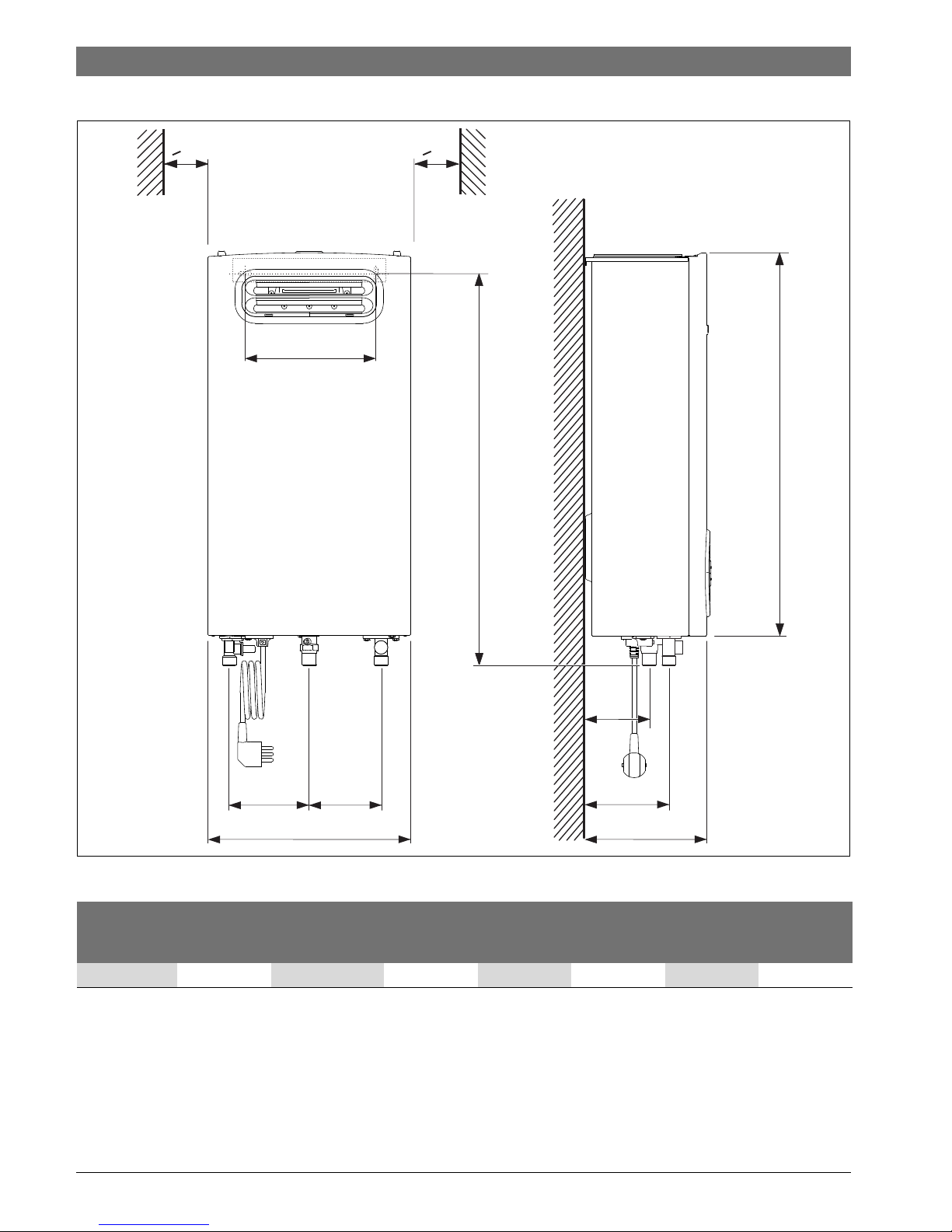
2.7 Dimensions and minimum clearances
Fig. 1 Dimensions (in mm)
B
C
240
A
583
6720808877-02.1V
>10 >10
107120
80
51
Connections
Water Gas
A B C Cold Hot Nat. LPG
GWH12 300 570 170 ½“ ½“ ½“ ½“
Table 4 Dimensions (in mm)
6 720 810 559 (2016/06)OptiFlow Professional
Product details | 7
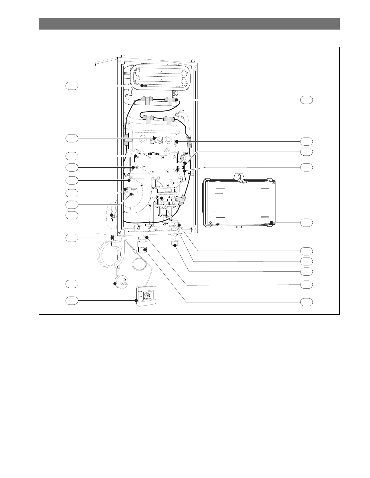
2.8 Appliance layout
Fig. 2
[1] Flue terminal
[2] Flame sensor rod
[3] Burner
[4] Air pressure test point
[5] Fan
[6] Air temperature sensor of the box
[7] Thermal fuse
[8] Hot water temperature sensor
[9] Hot water outlet
[10] Connecting lead with plug
[11] Remote control (optional)
[12] Ignition electrode
[13] Gas pressure test point
[14] Water flow sensor and Water valve
[15] Electronic control box
[16] Cold water temperature sensor
[17] Gas valve
[18] Cold water valve
[19] Incoming gas pressure test point
[20] Gas inlet
[21] Frost protection
6720808877-03.1V
10
2
3
4
5
8
9
6
7
11
15
13
14
20
18
19
17
16
21
12
1
6 720 810 559 (2016/06) OptiFlow Professional
8 | Product details
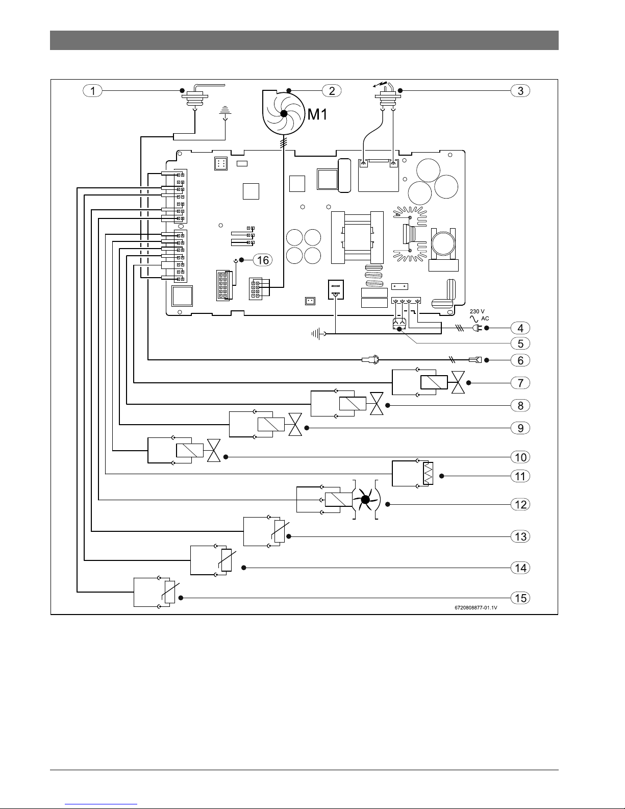
2.9 Electrical wiring diagram
Fig. 3 Electrical diagram
[1] Flame sensor rod
[2] Fan
[3] Ignition electrode
[4] Power supply
[5] Connection for frost-protection device
[6] Connection for remote control (optional)
[7] Modulation electrovalve (gas)
[8] Segmentation electrovalve 1 (gas
[9] Segmentation electrovalve 2 (gas)
[10] Safety electrovalve (gas)
[11] Thermal fuse
[12] Water flow sensor
[13] Air temperature sensor
[14] Hot water temperature sensor
[15] Cold water temperature sensor
[16] Water valve
 Loading...