

Bosch DAF220 Original Instructions Manual
© Robert Bosch Tool Corporation
1800 W. Central Road
Mt. Prospect, IL 60056-2230
Exportado por:
Robert Bosch Tool Corporation
Mt. Prospect, IL 60056-2230, E.U. A.
Importado a México por:
Robert Bosch, S.A. de C. V.,
Calle Robert Bosch No. 405,
Zona Industrial, Toluca, Edo. de México,
C.P. 50070, Tel. (722) 2792300
2 609 140 572 (09/08) T
Printed in Malaysia
3. MTR
4. BVL
SIMPLE MTR
C
OMPOUND MTR
1. SPR
2. CNR
MTR*
ON/CLEAR/OFF
RECALL/
H
OLD*
* PRESS FOR 1 SE
C
OND
DAF220
3. M
TR
4. B
VL
SIMPLE MTR
COMPOUND MTR
1. SPR
2. C
N
R
MTR
*
ON/C
LEAR/OFF
RE
CA
LL/HO
LD
*
* PRES
S
FO
R 1 SE
C
O
ND
DAF220
DAF220
us Original instructions
fr Notice originale
es Manual original
daf220_bu_2609140572_003.fm Seite 1 Montag, 8. September 2008 2:22 14
2 609 140 572 | (8.9.08) Bosch Power Tools
2 |
2
w
6
F
E
D
daf220_bu_2609140572_003.fm Seite 2 Montag, 8. September 2008 2:22 14
3 |
2 609 140 572 | (8.9.08) Bosch Power Tools
v
w
I
H
G
daf220_bu_2609140572_003.fm Seite 3 Montag, 8. September 2008 2:22 14
2 609 140 572 | (8.9.08) Bosch Power Tools
4 |
DAF220
3. MTR
4. BVL
SIMPLE MTR COMPOUND MTR
1. SPR
2. CNR
MTR*
ON/CLEAR/OFF
RECALL/HOLD*
R 1 SECOND
DAF220
3. MTR
4. BVL
MTR*
SIMPLE MTR COMPOUND MTR
1. SPR
2. CNR
ON/CLEAR/OFF
RECALL/HOLD*
* PRESS FOR 1 SECOND
3. MTR
4. BVL
SIM
PLE M
T
R
C
O
M
PO
UN
D
M
TR
1. SPR
2. CNR
MTR*
ON/CLEAR/OFF
RECALL/HOLD*
* PRESS FOR 1 SECOND
DAF220
2
1
14
13
6
4
6
5
12
11
10
9
7
8
3
3
ab
gfedc
14
4
2 607 001 312
15
1 609 203 X52
CB
A
daf220_bu_2609140572_003.fm Seite 4 Montag, 8. September 2008 2:22 14

2 609 140 572 | (8.9.08) Bosch Power Tools
6 |
General Safety Rules
WARNING! Read all
instructions. Failure to
follow all instructions
listed below may result
in electric shock, fire
and/or serious injury.
Safety Rules for
Anglefinders
f When using the angle informa-
tion provided by this tool to cut
materials, always observe all of
your saw’s instructions, including those for positioning and
clamping the workpiece. In
some cases, it may not be possible to set the required angles
on a particular saw or type of
saw, and an alternative means
of performing the cut will need
to be used.
f For extremely acute (sharp)
angles, it may be necessary to
make the cut using a taper jig
with a table saw or circular
saw.
Functional Description
Intended Use
The Bosch DAF220 Miterfinder™ is
a versatile angle measuring tool designed for the following uses:
– Anglefinder – Precisely mea-
sures the exact angle of existing
structure or workpiece.
– Protractor – Precisely positions
the workpiece or intended cut
line at the desired angle
– Miter Cut Calculator – Deter-
mines the exact miter setting
needed for simple miter cuts
daf220_bu_2609140572_003.fm Seite 6 Montag, 8. September 2008 2:22 14

| 7
Bosch Power Tools 2 609 140 572 | (8.9.08)
– Compound Miter Cut Calcula-
tor – Determines the exact miter
and bevel settings needed for
compound miter cuts, such as
crown molding cut
– Level – Built-in vertical and
horizontal spirit levels.
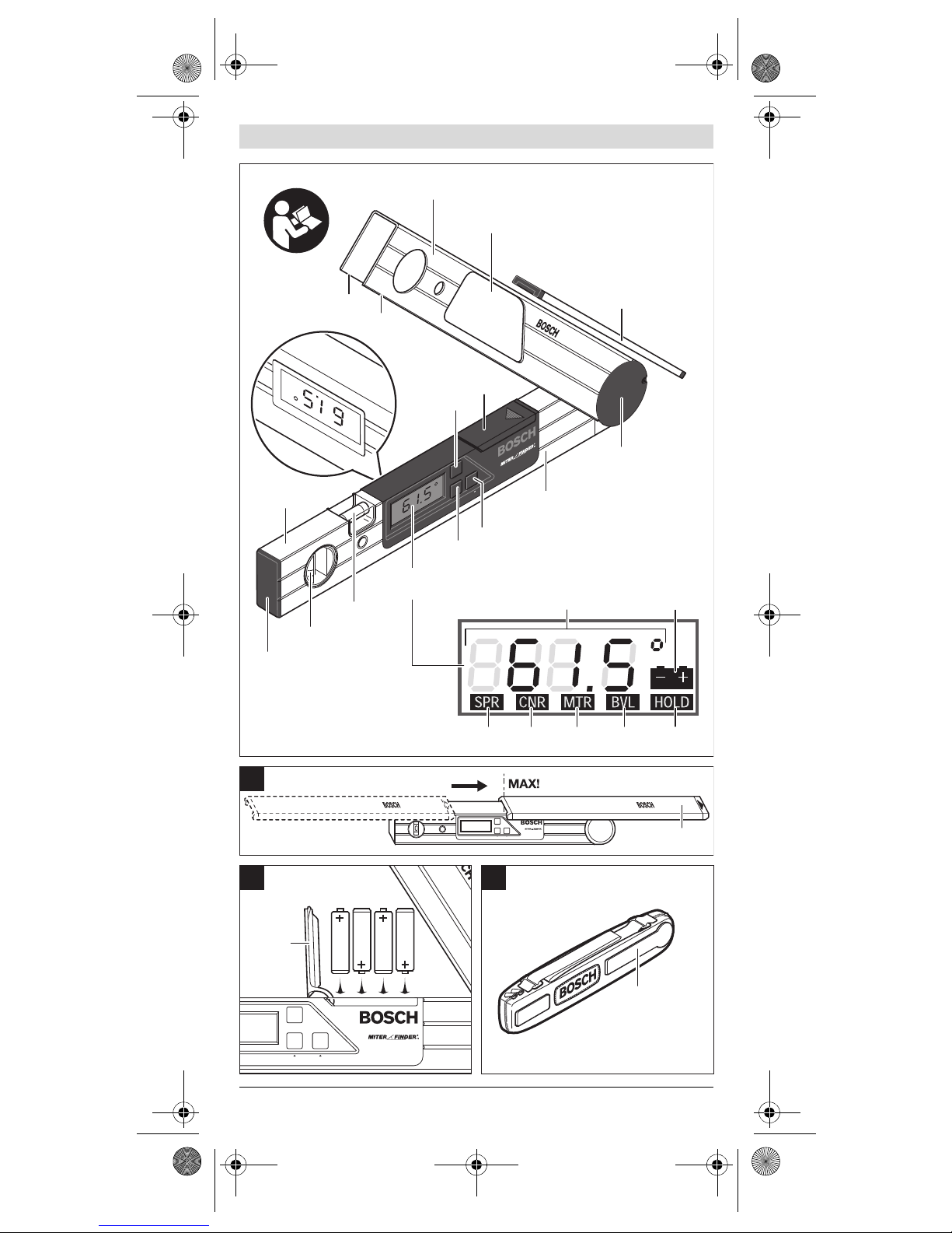
Product Features
1 Display Window
2 Adjustable Leg
3 Contact Edges
4 Battery Compartment Cover
5 RECALL/HOLD Button
6 Main Leg
7 End Cap
8 Spirit Level for vertical
alignment
9 Spirit Level for horizontal
alignment
10 LCD Display
11 ON/CLEAR/OFF & SIMPLE MTR
button
12 COMPOUND MTR button
13 Joint Cover
14 Leg Extension
15 Carrying Case
Display Element
a Angle Display
b Battery Power Indicator
c Spring Angle Indicator
(Input Angle No. 1 Indicator)
d Corner Angle Indicator
(Input Angle No. 2 Indicator)
e Miter Angle Indicator
f Bevel Angle Indicator
g HOLD (Memory) Indicator
daf220_bu_2609140572_003.fm Seite 7 Montag, 8. September 2008 2:22 14

2 609 140 572 | (8.9.08) Bosch Power Tools
8 |
Technical Data
Description Digital
Angle Finder
Model number
DAF220
Miterfinder™
Order number
3 601 K14 210
Measuring
range
0° … 220°
Measuring
accuracy
±0.1°
Calculated
angle accuracy
±0.1°
Operating
temperature
range
+15 °F … +120 °F
–10 °C … +50 °C
Storage
temperature
range
–5 °F … +185 °F
–20 °C … +85 °C
Power supply
Batteries or
rechargeable
batteries
4 x 1.5 V LR6 (AA)
4 x 1.2 V KR6 (AA)
Battery life
(Typ.)
(4 x 1.5 V
Batteries)
Approx. 130 H
Automatic
switch-off
After 3 minutes
without activity
Weight
(w/o extension)
Approx.
2.4 lbs/1070 g
Weight
(w/extension)
Approx.
2.7 lbs/1220 g
Leg length
16"/40 cm
Leg Extension
Range
0"–6-3/4"
or 170 mm
Spirit level
accuracy
±0.05°
(corresponds to
1 mm/m)
Dimensions
17"x1-3/8"x2-3/8"
(432x35x61) mm
U.S. Patent 6,104,480
daf220_bu_2609140572_003.fm Seite 8 Montag, 8. September 2008 2:22 14
| 9
Bosch Power Tools 2 609 140 572 | (8.9.08)
Spare Parts
Battery compartment
cover . . . . . . . . . . . . 1 609 203 928
End cap . . . . . . . . . .1 609 203 770
Joint cover. . . . . . . . 1 609 203 927
Preparation
Insert the batteries before putting
into operation for the first time.
Slide the battery compartment
cover 4 in the direction of the rectangle point and open. While inserting the batteries, make sure that
they are properly oriented
(see Figure B).
The tool automatically switches on
after the insertion of the batteries.
All display segments appear for
about 5 seconds while the unit performs a self check and calibration.
Once it is completed, the tool displays the “current angle”; that is,
the present angle between the legs.
When the battery indicator
stays on, it indicates that the batteries are running low and that
measurements can be made only
for about another 1–2 hours. If the
battery indicator starts to blink,
power is so low that measurements
are no longer possible, and the batteries must be replaced.
Switching On and Off
– ON: Press button 11. All seg-
ments of the angle display appear briefly.
– OFF: When the tool is in the nor-
mal measuring mode, press button 11 for less than 1 second.
After 3 minutes without button
actuation or angle change, the tool
switches off automatically to maximize battery life.
daf220_bu_2609140572_003.fm Seite 9 Montag, 8. September 2008 2:22 14
2 609 140 572 | (8.9.08) Bosch Power Tools
10 |
Exiting Special Modes
A press of 11 ON/CLEAR/OFF for
less than 1 second while the tool is
in the SIMPLE MTR or COMPOUND
MTR modes (or when HOLD [memory] is flashing) returns the tool to
the normal measuring mode.
Operation
Normal Measuring Mode –
Measuring the Angle of
Structure or Workpiece
(See Figure D–F)
1 Place both legs flat on the sur-
faces adjacent to the angle.
2 The “tool-interior angle” w (the
angle between the main leg 6 and
the adjustable leg 2) is measured.
3 The angle measurement in
degrees is shown in the display.
Notes:
– Contact surfaces and contact
edges must be clean. A dirty
surface will cause erroneous
measurements.
– For increased ability to see the
measurement, there are displays
on both the front and back sides
of the tool.
– When the angle between the
legs is changed, the angle measurement displayed is automatically updated.
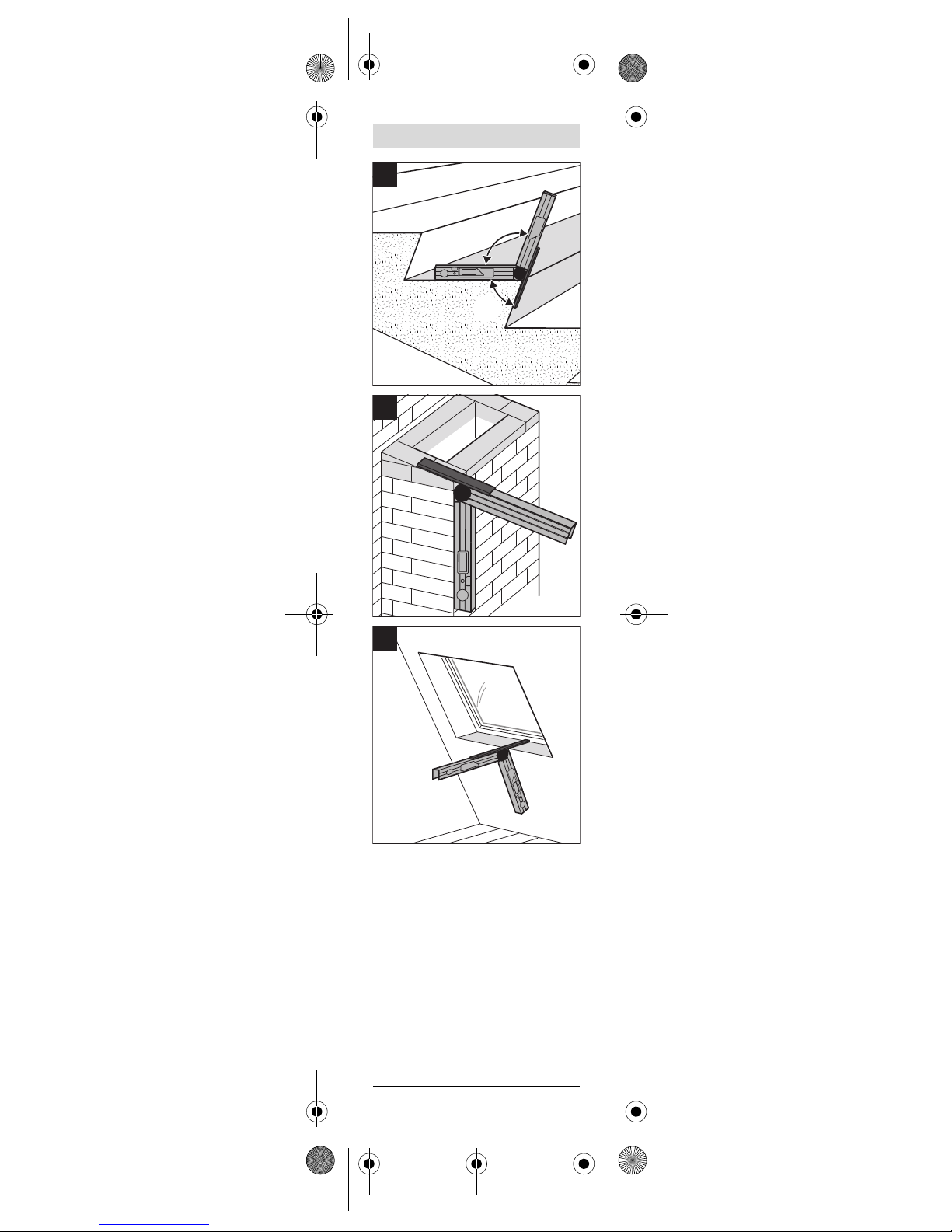
Using the Leg Extension
(Optional Attachment)
The leg extension makes it possible
to measure convex angles when
one of the contact surface areas is
too short to accommodate the
length of the legs.
– Slide the leg extension 14 onto
the adjustable leg 2 in the direction indicated by the arrow on
the extension.
daf220_bu_2609140572_003.fm Seite 10 Montag, 8. September 2008 2:22 14
| 11
Bosch Power Tools 2 609 140 572 | (8.9.08)
– The leg extension can be extend-
ed out up to 6-3/4" or 170 mm
(see Figure A).
– When the extension is used in
this way, the “tool-interior angle” w is displayed though it is
the “tool-exterior angle” v that
is needed (see Figure G). To
determine the “tool-exterior
angle”, subtract displayed angle
measurement from 180°
(v = 180°–w).
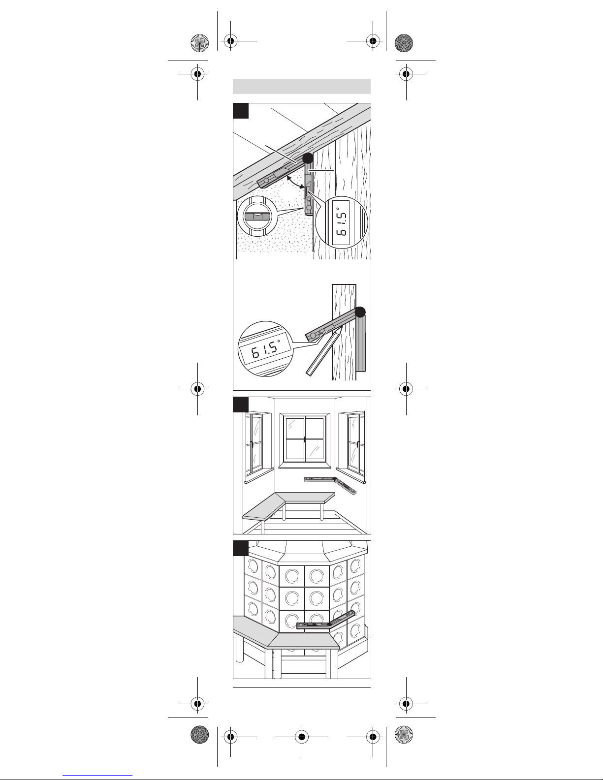
Examples of Leg Extension Usage
– Figure G illustrates the measure-
ment of a stairway step’s angle.
– Figure H illustrates the measure-
ment of the angle of the top of a
ventilation shaft that is to be
covered.
– Figure I illustrates the measure-
ment of a sloped window’s angle.
Transferring of Angles
(See Figure D)
The Miterfinder™ can also be used
to copy existing angles from one location to another:
1 Measure the angle to be copied
and keep the tool opened to that
angle.
2 Place the contact edges of the
tool onto the structure or workpiece and use the tool as a
straight edge to mark both legs
of the intended angle location.
Protractor
The Miterfinder™ can also be used
to position a workpiece or intended
cut line at exactly the desired angle
1 Open the tool to the desired
angle.
2 Please the tool into the intended
position of the work.
3 Use the tool as a straight edge to
mark both legs of the intended
angle location.
daf220_bu_2609140572_003.fm Seite 11 Montag, 8. September 2008 2:22 14

2 609 140 572 | (8.9.08) Bosch Power Tools
12 |
HOLD (Memory)
The hold memory is a single-value
memory that is useful for several
purposes:
– For storing a specific angle value
will be used repeatedly in compound cut calculations, such as
the common 38° crown molding
spring angle.
– For storing an angle measured in
a confined situation …
y when the display cannot be
seen when the measurement
is taken and
y when it is necessary to fold
the leg to move the tool so
that the display can be seen.
(For example, when measuring the angle of eaves from an
attic.)
Procedure
To store an angle in the HOLD
memory,
– Press the RECALL/HOLD button
5 for more than 1 second.
– The display and HOLD indicator g
blink twice of to confirm the successful storage of the angle.
To recall the stored angle, simply
press the RECALL/HOLD button 5
for less than 1 second. The recalled
angle then flashes in the display.
Notes:
– The tool maintains the stored
angle even after the tool is shutoff manually or automatically.
– However, if the battery power is
exhausted or when the batteries
are removed, the stored angle
will be lost and need to be restored after new batteries are installed.
– If the HOLD button is pressed
for more than 1 second when
0.0° is the displayed angle, any
stored angle is deleted.
daf220_bu_2609140572_003.fm Seite 12 Montag, 8. September 2008 2:22 14
| 13
Bosch Power Tools 2 609 140 572 | (8.9.08)
Determining Angles for
Simple Miter Cuts
The SIMPLE MTR feature determines miter angles for miter cuts
that are made with the blade vertically perpendicular to the workpiece; in other words, miter cuts for
which the bevel setting is set at 0°.
Such applications include mitering
baseboard and base shoe, chair
rail, picture rails, door frames, staircase balusters, and picture frames.
Procedure
1 Measure the joint’s angle by
placing the legs flat against the
surfaces adjacent to the angle.
2 Determine the miter angle by
pressing the SIMPLE MTR button for more than 1 second.
3 The necessary miter angle is
displayed and “MTR” appears in
the display.
4 Set the miter angle on the saw,
taking care to properly orient
the workpiece according the
saw’s instruction manual.
5 Return to the normal mea-
suring mode by pressing the
ON/CLEAR/OFF button for less
than 1 second.
Notes:
– To exit the SIMPLE MTR mode,
press ON/CLEAR/OFF for less
than 1 second.
– The DAF220 Miterfinder™ pro-
vides miter angle values for saws
with miter scales that have 0° as
the setting for a perpendicular
cut. When making miter cuts using tools that have 90° as the setting for perpendicular cuts (such
as many table saw miter gauges),
the MTR angle needs to be subtracted from 90° to calculate the
setting needed on such saws:
90° – MTR = correct miter setting for saws with 90° perpendicularity setting.
daf220_bu_2609140572_003.fm Seite 13 Montag, 8. September 2008 2:22 14
2 609 140 572 | (8.9.08) Bosch Power Tools
14 |
– Always observe all of your saw’s
instructions, including those for
positioning and clamping the
work pie ce. In s ome ca ses, it may
not be possible to set the required angles on a particular
saw or type of saw, and an alternative means of performing the
cut will need to be used. For extremely acute (sharp) angles, it
may be necessary to make the
cut using a taper jig with a table
saw or circular saw.
Determining Angles for
Compound Miter Cuts
The Miterfinder™ can be used to
easily determine the miter and
bevel angles needed to create precision joints at compound angles.
This is particularly useful when cutting crown molding laid flat on a
compound miter saw.
Procedure
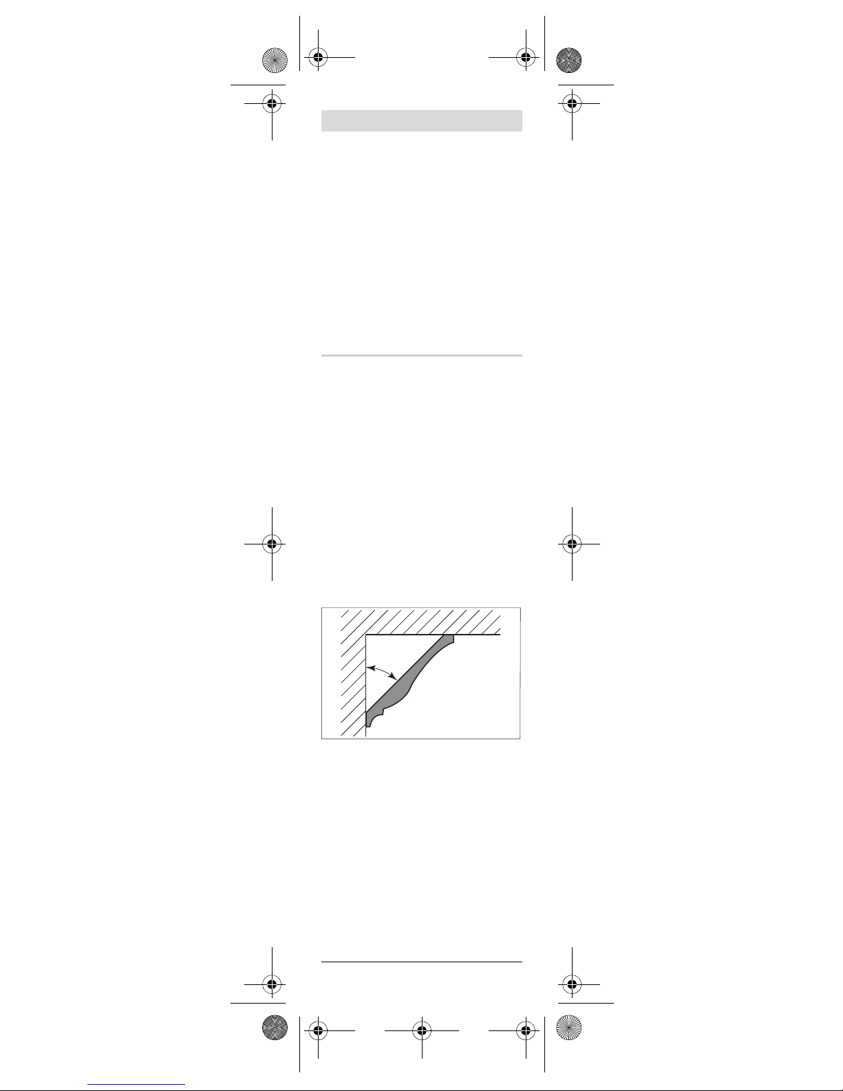
1) Set the Spring Angle
The spring angle is the angle between the back of the crown molding and the wall.
There are two ways to set the
spring angle:
A) Open The Tool to The Spring
Angle
– Open the legs to crown mold-
ing’s spring angle (typically 38°
or 45°).*
Ceiling
Ceiling
Spring
Angle
Spring
Angle
Wall
Wall
daf220_bu_2609140572_003.fm Seite 14 Montag, 8. September 2008 2:22 14

| 15
Bosch Power Tools 2 609 140 572 | (8.9.08)
– Set this value as the spring angle
by pressing the COMPOUND
MTR button.
– The entry is confirmed by the
appearance of “SPR” in the display.
OR
B) Recall A Spring Angle Stored
in “HOLD” (Recommended for
easy repeated use.)
See “HOLD (Memory)” section
– Press the RECALL/HOLD for less
than 1 second to recall the
stored angle.
– Set this value as the spring angle
by pressing the COMPOUND
MTR button.
– The entry is confirmed by the ap-
pearance of “SPR” in the display.
– The main display reverts to
showing the angle to which the
tool is opened.
* To determine the spring angle; see
“How to Determine The Spring Angle of
A Crown Molding” section below
daf220_bu_2609140572_003.fm Seite 15 Montag, 8. September 2008 2:22 14
2 609 140 572 | (8.9.08) Bosch Power Tools
16 |
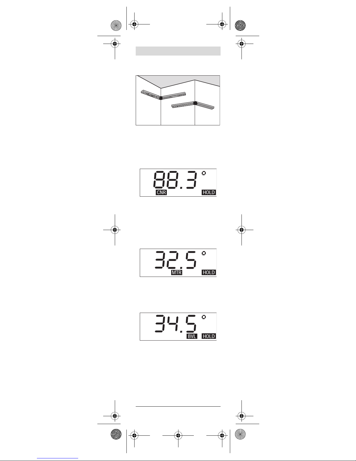
2) Measure the Corner Angle
– Place the legs flat on the walls.
– Store the corner angle by again
pressing the COMPOUND MTR
button.
– The entry is confirmed by the ap-
pearance of “CNR” in the display.
3) Determine the Miter Angle &
Bevel Angles
– Press the COMPOUND MTR
button again to display the necessary miter angle
– “MTR” appears in the display.
– Press the COMPOUND MTR
button again to display the necessary bevel angle.
– “BVL” appears in the display.
– If necessary, the miter angle can
be retrieved by pressing the
COMPOUND MTR button again.
daf220_bu_2609140572_003.fm Seite 16 Montag, 8. September 2008 2:22 14

| 17
Bosch Power Tools 2 609 140 572 | (8.9.08)
4) Set the Miter and Bevel Angles
on the Saw, taking care to prop-
erly orient the workpiece according the saw’s instruction
manual.
5) Return to the Normal Measuring Mode
– Press the ON/CLEAR/OFF but-
ton (for less than 1 second) to
exit the Compound MTR mode
and return to the normal measuring mode.
– The current angle appears in the
main display.
Notes:
– When dealing with compound
angle situations other than the
cutting of crown molding laid
flat, one of the measured structure or workpiece angles should
be treated as though it were a
spring angle (SPR) and the other
as the corner angle (CNR).
– If a measured angle is outside
the range of 0° to 180°, “– – – –”
appears in the display for about
2 seconds, then the tool reverts
to the normal measuring mode.
– To exit the COMPOUND MTR
mode, press ON/CLEAR/OFF for
less than 1 second.
– The DAF220 Miterfinder™ pro-
vides miter angle values for saws
with miter scales that have 0° as
the setting for a perpendicular
cut. When making miter cuts using tools that have 90° as the setting for perpendicular cuts (such
as many table saw miter gauges),
the MTR angle needs to be subtracted from 90° to calculate the
setting needed on such saws:
90° – MTR = correct miter setting for saws with 90° perpendicularity setting.
daf220_bu_2609140572_003.fm Seite 17 Montag, 8. September 2008 2:22 14
2 609 140 572 | (8.9.08) Bosch Power Tools
18 |
– Always observe all of your saw’s
instructions, including those for
positioning and clamping the
work pie ce. In s ome ca ses, it may
not be possible to set the required angles on a particular
saw or type of saw, and an alternative means of performing the
cut will need to be used. For extremely acute (sharp) angles, it
may be necessary to make the
cut using a taper jig with a table
saw or circular saw.
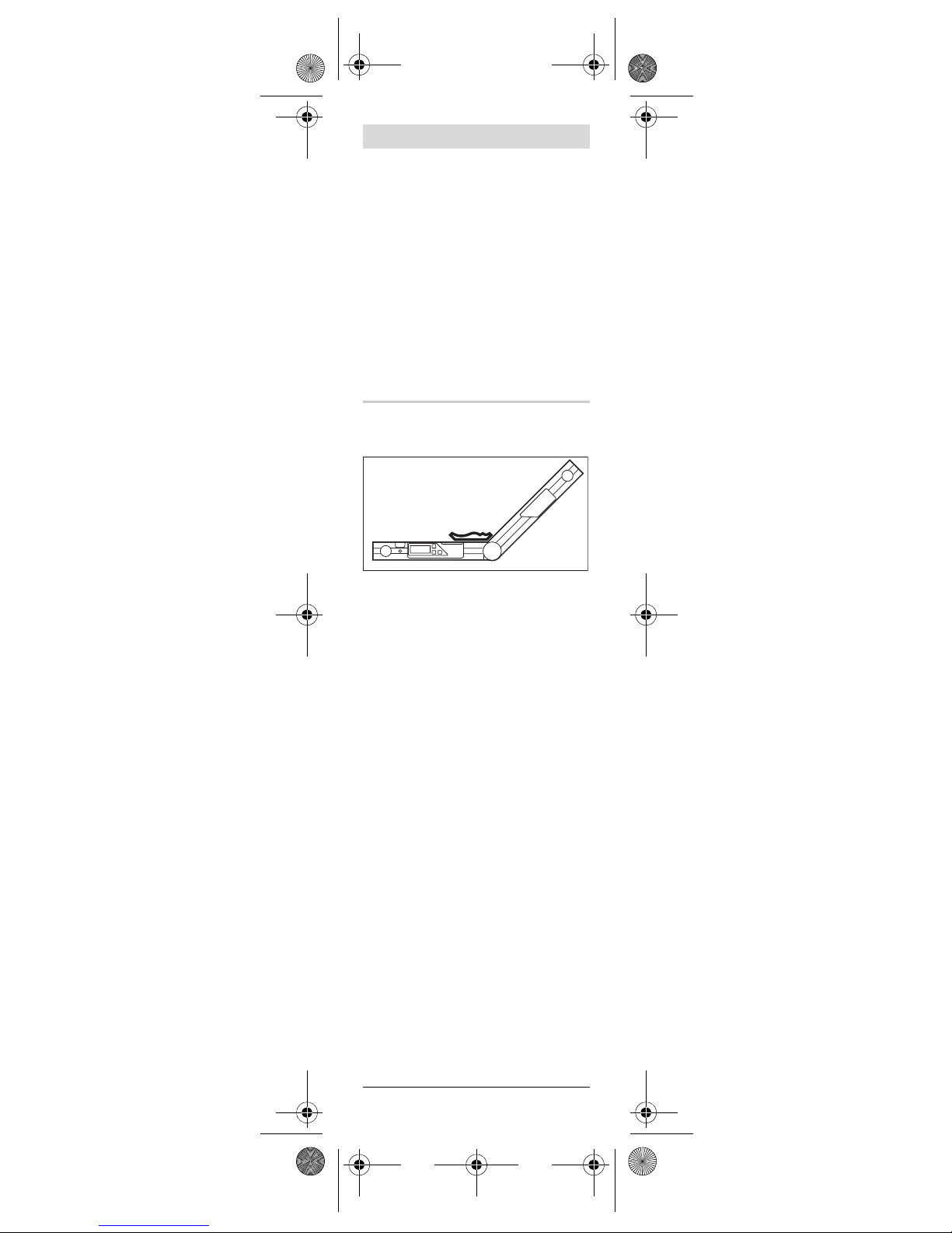
How to Determine The Spring
Angle of A Crown Molding
1 Place the crown molding on the
Miterfinder™ as shown in Figure.
Note that the back of the crown
molding must be placed on the
top of the tool’s main leg 6 and
that the lower edge of the crown
molding must face the adjustable
leg 2.
2 Open the adjustable leg to the
angle that exactly matches the
lower edge of the crown molding.
3 Subtract displayed angle mea-
surement from 180° to determine the spring angle.
Notes:
– The lower edge is typically the
more-detailed edge of the crown
molding.
– The most common crown mold-
ing spring angles are 38° and 45°.
daf220_bu_2609140572_003.fm Seite 18 Montag, 8. September 2008 2:22 14
| 19
Bosch Power Tools 2 609 140 572 | (8.9.08)
Troubleshooting
Issue Remedy
Noise is
coming
from area
between
the tool’s
legs
No action typically
required. The sound
is from the motor is
used to measure
the angle between
the legs.
MTR value
doesn’t
correspond
to the miter
scale on a
particular
saw.
The Miterfinder provides miter angle
values for saws with
miter scales that
have 0° as the setting for a perpendicular cut.
When making miter
cuts on tools that
have 90° as the perpendicular cut setting, the MTR angle
provide by the
Miterfinder needs
to be subtracted
from 90°.
It is not
clear as to
how to position the
workpiece
on the saw.
Follow the saw’s
instructions regarding the positioning
and clamping of the
workpiece.
Battery
symbol is
flashing
Replace batteries
“– – – –”
appears in
display
The tool is not
designed to perform the desired
operation
daf220_bu_2609140572_003.fm Seite 19 Montag, 8. September 2008 2:22 14
 Loading...