

Page 1
D7048(B) Octal Driver Module
Installation Guide
1.0 Notice
These instructions cover the installation of the Radionics D7048(B) Octal Driver Modules in a fire system supervised
by a Radionics D7024 Fire Alarm Panel (FACP).
Install, test and maintain the D7048(B) according to their instructions, NFPA 72, Local Codes and the Authority Having
Jurisdiction. Failure to follow these instructions may result in failure of the device to operate properly. Radionics is not
responsible for improperly installed, tested or maintained devices.
These instructions contain procedures to follow in order to avoid personal injury and damage to equipment.
Test the D7048(B) in accordance with NFPA 72.
2.0 Device Description
The D7048(B) is a Solid State Octal Driver Module that provides eight open collector transistor outputs for addition to
the D7024 Fire Alarm Control/Communicator. It connects to the panel via the Option Bus. The outputs are fully
programmable and can be activated by several system events. Each output operates individually of the other seven
outputs for complete flexibility.
3.0 Installation
The D7048(B) is static-sensitive. Use proper static controls when handling the D7048(B).
Before installing the D7048(B), disconnect all power (AC and battery) from the system. Failure to do so may
result in personal injury and/or damage to the equipment.
3.1 Installing the D7048 inside the FACP Enclosure
Use the following steps when installing the D7048 inside the FACP enclosure:
1) Disconnect all power from the FACP by turning off the AC supply circuit and disconnecting the red battery lead.
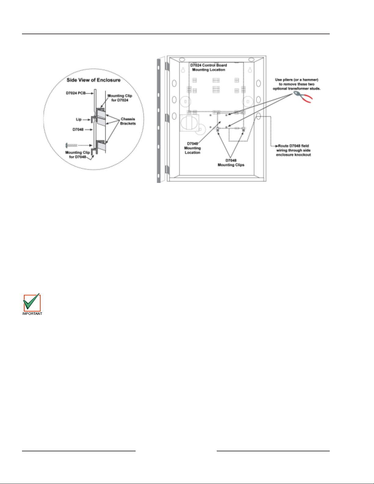
2) Remove the two optional transformer studs from the enclosure using either pliers or a hammer to rock them
loose. Push the studs back through the enclosure. If the enclosure is already mounted, pull the studs forward
through the back of the enclosure instead of pushing them back. See Figure 1 for details.
Page 2
D7048(B)
Installing the D7048(B)
Figure 1: Installing the D7048 in the D7024 Enclosure
3) Place the mounting clips in the enclosure as shown in Figure 1.
4) Insert the upper length of the D7048 board underneath the lips of the mounting clips holding the control panel
board in place. See Figure 1.
5) Fasten screws through the lower mounting holes on the D7048 and mounting clips from step 3. See Figure 1.
6) Refer to section 4.0 for wiring instructions.
3.2 Installing the D7048B Outside the FACP Enclosure
The preferred mounting for the D7048 is directly inside the FACP enclosure, using the provided mounting site. The
D7048B kit (which contains a D7048 Octal Driver Module, one MP-D203 Mounting Skirt, and one AE203R Fire
Enclosure) may, however, be mounted in its own enclosure near the FACP using the following procedure.
The D7048B may be mounted up to 250 feet (76 m) from the D7024 panel using #18 AWG (1.2 mm) wire. No
more than 4,000 ft. (1,219 m) of wire may be attached to the FACP option bus terminals. Refer to the F ACP’ s
installation manual for additional option bus wiring information. The length of wiring connected to the outputs
on the D7048(B) must be less than 20 ft. (6.1 m).
1) Choose an appropriate location for the AE203R enclosure.
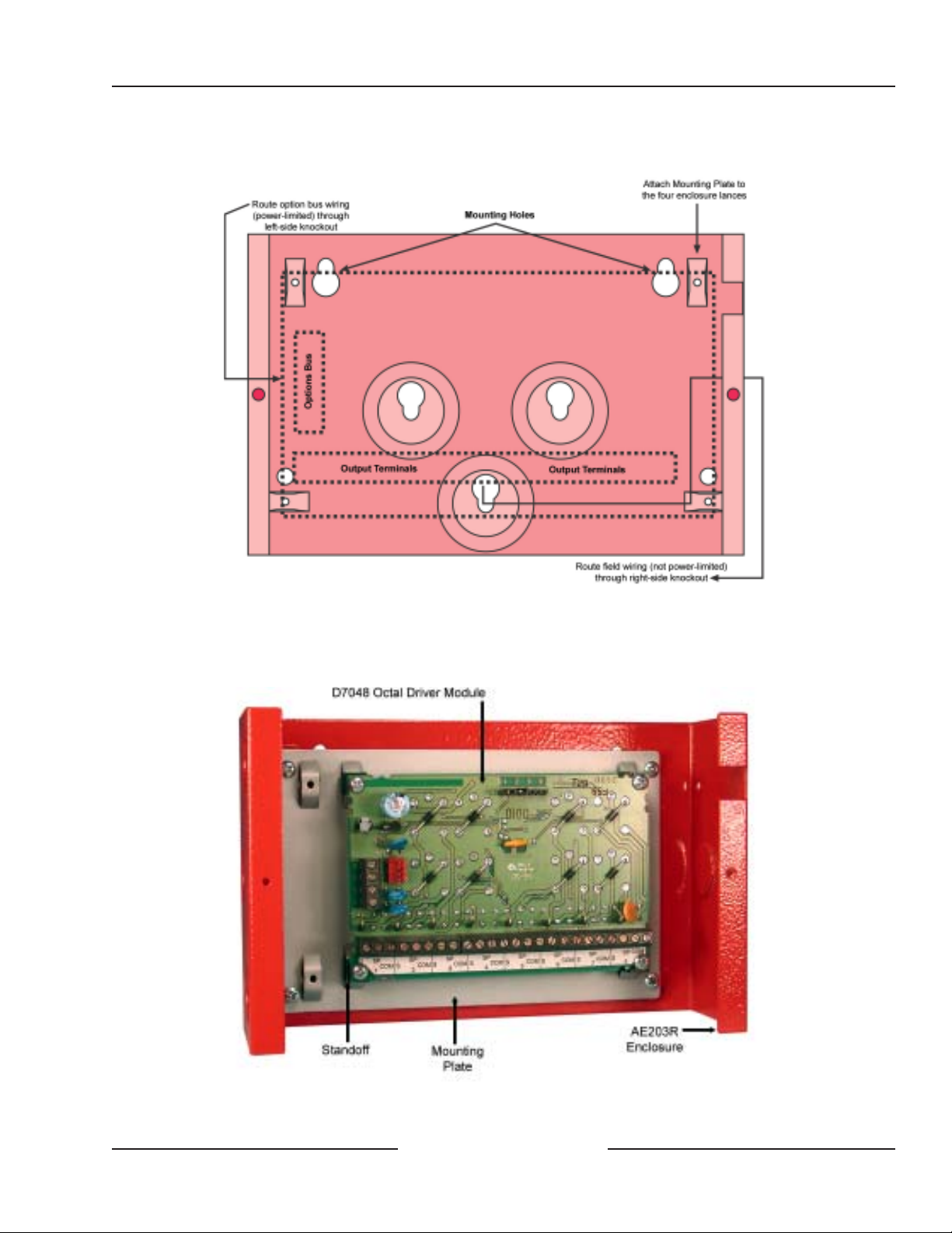
2) Using the enclosure as a template, mark the mounting holes on the mounting surface and make openings for the
unit’s wiring. It is recommended that the option bus wiring enter the AE203R enclosure from the left and the
D7048 output wiring exit the enclosure to the right. See Figure 2.
D7048(B) Installation Guide
48606C Page 2 Copyright © 2002 Radionics
Page 3
D7048(B)
Installing the D7048(B)
Figure 2: Mounting the AE203R Enclosure
3) Snap the four plastic standoffs onto the appropriate raised tabs on the mounting skirt (see Figure 3) and then use
the longer supplied screws to attach the D7048 module to the plastic standoffs.
Figure 3: Mounting Plate Assembly
D7048(B) Installation Guide
Copyright © 2002 Radionics Page 3 48606C
Page 4

D7048(B)
Wiring the D7048(B)
4) Attach the mounting skirt (with the circuit board attached) to the AE203R enclosure using the hardware provided.
See Figure 2 and/or Figure 3.
5) Refer to section 4.0 for wiring instructions.
4.0 Wiring the D7048(B)
For UL listed fire applications, minimum #18 A WG (1.2 mm) wire is required. All wiring outside the enclosure
must be in conduit.
Observe these cautions when wiring the D7048(B):
• Observe correct polarity when wiring the D7048(B). Reversing polarity may damage the unit.
• Never attempt to switch AC Line voltages with this device. Switching AC Line voltages will place dangerous
voltages inside the panel and will damage the panel and its modules. If external power supplies are used, they
must be fully isolated from the AC Lines.
• Do not use voltages over 12 VDC or any AC voltages on the D7048(B). Voltages over 12 VDC may damage the
D7048(B) and the control panel.
• Avoid earth grounding any wires or terminals on this device.
• Do not exceed 50 mA maximum per device (240 mA total).
• All Commons on the D7048(B) are tied together to Option Bus Negative (-). Do not mix voltages and power
supplies.
• For D7048B, route power-limited wiring (option bus) away from non-power limited (field wiring). See Figure 2.
The D7048(B) is wired to the control panel’s option bus. See Figure 4.
Figure 4: Option Bus Wiring
All option bus devices must be connected to the same bus (either Bus A or Bus B). Do not connect some
devices to Bus A data terminals (YA, GA) and some to Bus B (YB, GB). Power (RA and RB terminals) and
ground (BA and BB) may be connected interchangeably to either set of terminals.
D7048(B) Installation Guide
48606C Page 4 Copyright © 2002 Radionics
Page 5

To wire the contacts, see Figure 5. See Table 1 for terminal designations.
Figure 5: Output Wiring
Terminal Function
S Sink. This terminal switches the applied voltage to common when acti vated.
SP Spare. Not used.
COM Common. All Commons are tied together.
Table 1: T erminal Designations
For typical wiring examples of commonly used devices, see Figure 6.
D7048(B)
Wiring the D7048(B)
Figure 6: Typical W iring Examples
D7048(B) Installation Guide
Copyright © 2002 Radionics Page 5 48606C
Page 6

D7048(B)
Selecting Option Bus Address & Programming
5.0 Selecting the Option Bus Address
The D7048(B) must be selected as an option address 1-15. Use the Option Address Pins to select an option address
with the jumper plugs provided. See Figure 7.
Figure 7: D7048(B) Option Bus Addresses
6.0 Programming the D7048(B)
The D7048(B) must be programmed through the control panel. See your control panel’s installation guide for output
programming information.
D7048(B) Installation Guide
48606C Page 6 Copyright © 2002 Radionics
Page 7

7.0 Specifications
Control Panel Compatibility
Operating Voltage 12 VDC option bus power
Current Draw
Outputs
Wiring
D7048(B)
Specifications
D7048/D7048B Specifications
D7024 Fire Alarm Control/Communicator (FACP)
10 mA
Provides a current sink [the output shorts to Common (-) when activated].
Maximum current draw for all eight outputs combined cannot exceed 240 mA.
Refer to th e
The length of wiring connected to each of the outputs on the D7048(B)
D7024 Operation and Installation Guide
Unsupervised outputs.
(P/N: 31499)
for option bus wiring lengths.
must be less than 20 feet (6.1 m).
D7048(B) Installation Guide
Copyright © 2002 Radionics Page 7 48606C
Page 8

© 2002 Radionics, a division of Detection Systems, Inc. 48606C 2/02
PO Box 80012, Salinas, CA 93912-0012 USA Installat ion G uide D7048(B)
Customer Service: (800) 538-5807 Page 8 of 8
 Loading...