

Page 1
D7042/D7042B Multiplex Eight Input Remote Modules
Installation Instructions
1.0 Introduction
These instructions cover the installation of the D7042/D7042B Eight Input Remote Modules in a fire system supervised
by an FPD-7024 Fire Alarm Control Panel (FACP).
Install, test and maintain the D7042/D7042B Eight Input Remote Modules according to their instructions, NFPA 72,
Local Codes and the Authority Having Jurisdiction. Failure to follow these instructions may result in failure of the
device to operate properly. Bosch is not responsible for improperly installed, tested or maintained devices.
These instructions contain procedures to follow in order to avoid personal injury and damage to equipment.
2.0 Device Description
The D7042/D7042B is an Eight Input Remote Module that provides a means of addressing up to eight input loops of
conventional contacts to the multiplex bus of the control panel. It is suitable for use with the FPD-7024 Fire Alarm
Control Panel (FACP) with ROM version 2.0 or greater using a D7039 Multiplex Expansion Module. Up to 30 D7042/
D7042B modules can be supported per FACP. One D7039 Multiplex Expansion Module is required in the system to
use the D7042/D7042B Eight Input Remote Modules.
3.0 Installing the D7042/D7042B
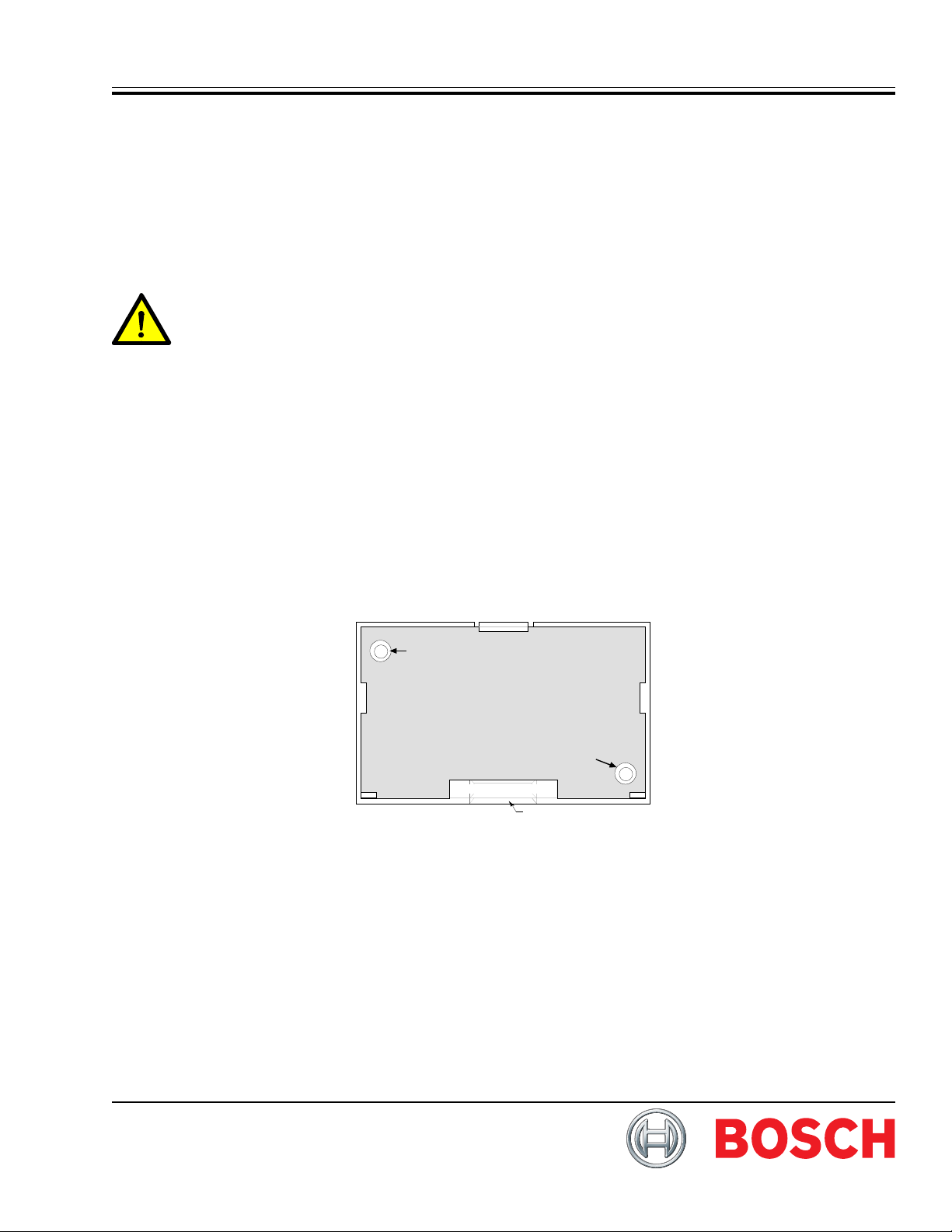
3.1 Mounting the D7042
Use the mounting holes (upper left and lower right corners) to mount the D7042. The D7042 normally is mounted
outside of the FACP enclosure.
Mounting Hole
Mounting Hole
Rear Wire Entrance
Surface Wire Entrance
Figure 1: Mounting the D7042
Page 2
D7042/D7042B
Installation Instructions
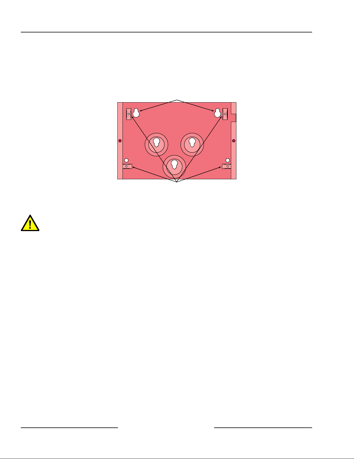
3.2 Mounting the D7042B
The D7042B will come partially preassembled with the circuit board attached to the mounting skirt.
Select a mounting location for the D7042B.
Using the enclosure as a template, mark the mounting holes on the mounting surface and make an opening for the
unit’s wiring.
Next, attach the mounting skirt if applicable (with the circuit board attached) to the enclosure (hardware provided).
Then complete all wiring (see Section 4.0). Once installation and wiring is completed, attach the enclosure cover and
secure with the screws (provided).
Mounting Holes
Attach Mounting Skirt He re
Figure 2: Mounting the D7042B
Be sure all wiring is unpowered before routing. Do not use shielded or twisted pair cable.
Refer to the D7039 Installation Guide (P/N: 38685) for multiplex wiring requirements. The length of the wire connected
to the loop inputs on the D7042/D7042B must be less than 250 ft. (76 m) per loop. Route wiring as necessary from the
D7039 in the FACP enclosure and from remote devices to the D7042/D7042B. If the wiring is to run along the surface
of the enclosure, open the D7042/D7042B surface wire entrance. See Figure 2.
D7042/D7042B Installation Instructions
F01U 2 62 01 4- 0 1 Page 2 © 2011 Bosch Security Systems, Inc.
Page 3
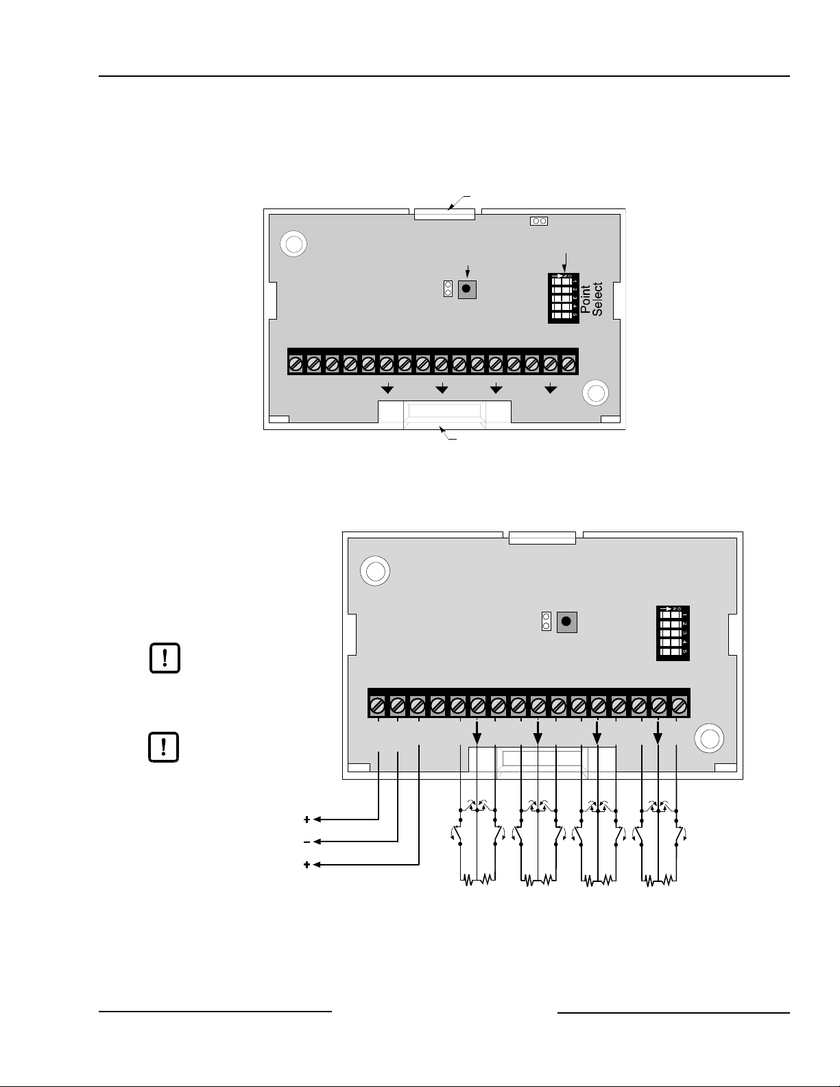
4.0 Wiring
Installation Instructions
Locking tab
P3
Tamper Switch
P2
+–+–12345678
POWER BUS
Rear Wire Entrance
Surface Wire Entrance
DIP switch
D7042/D7042B
Since NFPA 72 does not allow
redundant/duplicate ground paths,
do not connect wiring to the BUS (-)
terminal on this module for fire
applications. Only the BUS (+) needs
to be connected.
When used with a D7039, power is
connected to the option bus power
terminals (RA or RB (+), BA or BB (-)).
Connection t o 24 VDC sources will
damage the D7042/D7042B.
T o D7024 Opt io n Bus RA (or RB) terminal
T o D7024 Option Bus BA (or BB) terminal
To D7039 MUX
bus terminal
Figure 3: D7042/D7042B Front View without Cover
P2
+ –
+ –
POWER
BUS
1 2
NO NO
NC NC
47 k ohm
resistors
3 4
NO NO
NC NC
47 k ohm
resistors
EOL P/N: 28010
5 6
Figure 4: Wiring the D7042/D7042B
NO NO
NC NC
47 k ohm
resistors
7 8
NO NO
NC NC
47 k ohm
resistors
D7042/D7042B Installation Instructions
© 2011 Bosch Security Systems, Inc. Page 3 F01U262014-01
Page 4

D7042/D7042B
Installation Instructions
DS9400 FACP
DS9431Multiplex Expansion Module
Trouble
Power
Silenced
Alarm
Drill
21 3
4 5 6
7 8 9
0
Prog
Clear
*
Silence
Disable
Test
Reset
#
History
Cmnd
SMK+
SMKAUX+
AUX-
4L+
32L+
1-
12V Power (-)
12V Power (+)
Power + may be conn ect ed t o RA or RB
on the FACP Option Bus terminal strip.
Power - may be connected to BA or BB on
the FACP Option Bus.
DS7432 Eight Input Remote Module
+– 23 45 67 8
+ –
1
BUS
POWER
24V Smoke Power (+)
24V Smoke Power (-)
I/O Module for the
DS9431 Multiplex
Expansion Module
Bus (+)
Bus + and Bus - are connected to
MUX A terminals for addresses 9 -
128. MUX B terminals are for
addresses 129 - 255.
NFPA 72 does not allow redundant/duplicate
ground paths, do not connect wiring to the
BUS (-) te rminal on th is m odule for fire
applications. Only the BUS (+) needs to be
connected.
Figure 5: Wiring Four-wire Smoke Detectors
EOL
Resistor
P/N: 28010
Smoke
Detector
Smoke
Detector
EOL
Relay
Example:
DS250 in a MB4W base
Example: EOL200
D7042/D7042B Installation Instructions
F01U 2 62 01 4- 0 1 Page 4 © 2011 Bosch Security Systems, Inc.
Page 5

5.0 Programming the D7042/D7042B
Refer to the programming section of the D7024 Reference Guide (P/N: 31499) for point programming information.
The D7042/D7042B occupies eight multiplex point addresses when connected to the control panel.
6.0 Setting the Jumpers and DIP Switches
6.1 D7042 Jumper Settings
P2 of the D7042/D7042B allows the tamper switch to be bypassed with a jumper when testing or servicing.
Remove the jumper on P2 when testing or servicing has been completed.
6.2 D7042/D7042B DIP Switch Settings
The DIP switches select which points will be activated by the loop inputs.
Set the DIP switches as shown in Table 1.
No two D7042/D7042B DIP Switch settings should be the same.
The D7042/D7042B occupies eight points when connected to the FACP.
The input loops of the D7042/D7042B correspond to the points of the
FACP as shown in Table 2. Figure 6 shows the DIP switch positions for
on and off settings.
D7042/D7042B
Installation Instructions
Figure 6: D7042/D7042B DIP Switch
D7042/D7042B Installation Instructions
© 2011 Bosch Security Systems, Inc. Page 5 F01U262014-01
Page 6

D7042/D7042B
Installation Instructions
stnioP 1 2 3 4 5
61-9ffOffOffOffOnO
42-71ffOffOffOnOffO
23-52ffOffOffOnOnO
04-33ffOffOnOffOffO
84-14ffOffOnOffOnO
65-94ffOffOnOnOffO
46-75ffOffOnOnOnO
sehctiwSPID
27-56ffOnOf
08-37ffOnOffOffOnO
88-18ffOnOffOnOffO
69-98ffOnOffOnOnO
401-79ffOnOnOffOffO
211-501ffOnOnOffOnO
021-311ffOnOnOnOffO
821-121ffOnOnOnOnO
63
1-921nOffOffOffOffO
441-731nOffOffOffOnO
251-541nOffOffOnOffO
061-351nOffOffOnOnO
861-161nOffOnOffOffO
671-961nOffOnOffOnO
481-771nOffOnOnOffO
291-581nOffOnOnOnO
fOffOffO
002-391nOnOffOffOffO
802-102nOnOffOffOnO
612-902nOnOffOnOffO
422-712nOnOffOnOnO
232-522nOnOnOffOffO
042-332nOnOnOffOnO
842-1
42nOnOnOnOffO
T able 1: D7042/D7042B DIP Switch Settings
D7042/D7042B Installation Instructions
F01U 2 62 01 4- 0 1 Page 6 © 2011 Bosch Security Systems, Inc.
Page 7

D7042/D7042B
Installation Instructions
rebmuNtnioP
tupnIB2407D/2407D
pooL
61-9stnioP901112131415161
42-71stnioP7181910212223242
23-52stnioP5262728292031323
04-33stnioP3343536373839304
84-14stnioP1424344454647484
65-94st
nioP9405152535455565
46-75stnioP7585950616263646
27-56stnioP5666768686071727
08-37stnioP3747576777879708
88-18stnioP1828384858687888
1 2 3 4 5 6 7 8
69-98stnioP98091
401-79stnioP798999001101201301401
211-501stnioP501601701801901011111211
021-311stnioP311411511611711811911021
P121221321421521621721821
ioP771871971081181281381481
821-121stnio
631-921stnioP921031131231331431531631
441-731stnioP731831931041141241341441
251-541stnioP54164174184194105115
061-351stnioP3514515516517518511951061
861-161stnioP161261361461561661761861
671-961stnioP961071171271371471571671
481-771stn
291-581stnioP581681781881981091191291
002-391stnioP391491591691791891991002
802-102stnioP10220230240250260
612-902stnioP902012112212312412512612
92939495969
1251
2702802
422-712stnioP712812912022122222322422
232-522stnioP522622722822922032132232
nioP332432532632732832932042
042-332st
842-142stnioP142242342442542642742842
T able 2: Loop/Point Number Relationship
D7042/D7042B Installation Instructions
© 2011 Bosch Security Systems, Inc. Page 7 F01U262014-01
Page 8

7.0 Specifications
B2407D/2407D
warDtnerruC
)rewopsubnoitpomorf(
warDtnerruC
)poolsubxelpitlummorf(
yrettaBrofwarDtnerruClatoT
mralAdnanoitaluclaCybdnatS
B.niMkaepCDV8
egatloVgnitarepOsu
gniriWsuBxelpitluMehtotrefeR ediuGnoitallatsnI9307D )58683:N/P(
gniriWpooLmralAlacoL muminim)m
egnaRerutarepmeTgnitarepO )C°94+otC°0+(F°021+otF°23+
mralAdnaybdnatSAm8
aybdnatSAm01
mralAdn
mralAdnaybdnatSAm81
m2.1(GWA81#;.xam)m2.67(.tf052
© 2011 Bosch Security Systems, Inc.
130 Perinton Parkway, Fairport, New York, USA 14450-9199
Installation Instructions D7042/D7042B
F01U262014-01 12/11
Page 8 of 8
 Loading...