

Bosch B921C Installation Manual
1 | Overview
3 | Installation
3.3 | Sensor loop wiring
The B921C keypad is a SDI2 bus compatible device. Each
keypad has user adjustable options such as volume and
display brightness, and an LCD display that shows two-line
system messages. The keypad features capacitive keys.
The B921C connects to the SDI2 bus on the control panel
using terminal wiring. You can connect more than one keypad
to the control panel by wiring them in parallel.
You can program, diagnose, and troubleshoot the system from
the control panel keypad as well as remotely through Remote
Programming Software (RPS).
You can wire up to 4 inputs to the keypad.
1
3
11
5
7 7
1COM2 3COM4
6
6
4
1
2
R Y G B
2
1
11
5
9
10
11
8
3
5
6
Figure 1.1: Keypad base overview
Callout ― Description
1 3 in octagon box holes
2 Single gang box holes
3 Double gang box holes
4 Wire opening
5 Surface mount wire openings
6 4 in square box or wall mount holes
7 Surface mount wire channel
8 Bubble level
9 SDI2 wiring terminal block
10 Inputs wiring terminal block
11 Wire tie posts
2 | SDI2 address switches
Two switches determine the address for the keypad. The control
panel uses the address for communications. Use a slotted
screwdriver to set the switches.
2 | Access the address switches
1. Unlock the keypad by turning the lock counter-clockwise.
Refer to Figure 2.1.
2. Hold the keypad by the base in one hand. With the other
hand, gently push down on the keypad to remove it from
the base. Refer to Figure 2.2.
3. Look at the back of the keypad, and locate the switches.
Figure 2.1: Unlocking the keypad
Figure 2.2: Removing the keypad from base
2.2 | Set the address switches
Set the address switches per the control panel confi guration.
If multiple SDI2 keypads reside on the same system, each
SDI2 keypad must have a unique address. For single-digit
addresses 1 through 9, set the tens switch to 0. Figure 2.4
shows the address switch setting for address 1.
Figure 2.3: Address switches
2.3 | Understand addresses and point numbers
To determine the point numbers for each keypad address,
multiply the address number by 10 for the base number, and
then use numbers 1 through 4 in the ones place for the point
numbers.
Examples
For B921C address 01 the point numbers for the input devices
are 11 through 14:
Terminal number 1234
Point number 11 12 13 14
For B921C address 11 the point numbers for the input devices
are 111 through 114:
Terminal number 1234
Point number 111 112 113 114
After you set the address switches for the proper address,
mount the keypad base, wire to the control panel, and attach the
keypad to the base.
3.1 | Mount the keypad
You can surface mount the keypad, or mount it to standard
electrical boxes, including single and double gang boxes.
Mounting the keypad:
1. Use the base as a template to mark the desired mounting
surface. Refer to Figure 1.1 for mounting hole and wiring
locations.
2. Pull the wiring through the desired wire opening in the
base.
3. Use the appropriate mounting hardware (supplied) to
mount the base to the desired mounting surface. Refer to
Figure 1.1 for mounting hole and wiring locations
.
3.2 | Wire to the control panel
When you wire the keypad to a control panel, use the control
panel terminals labeled R, Y, G, B (PWR, A, B, COM). Connect
them to the keypad terminals labeled R, Y, G, B.
Refer to Figure 3.1.
You can connect keypads to the SDI2 data bus by parallel wire
run from the control panel to each keypad, wire from keypad to
keypad, or a combination of the two techniques.
Refer to Figure 3.2.
Figure 3.1: Wiring the keypad to the SDI2 bus connection
(B5512 shown)
Callout ― Description
1 Control panel
2 Terminal wiring
3 Keypad’s SDI2 wiring terminal block
Figure 3.2: Installing multiple keypads using the SDI2 terminals
Reconnect the keypad to the base by sliding the keypad onto
the base (reverse of Step 2). The keypad automatically locks
onto the base. Apply power to the system.
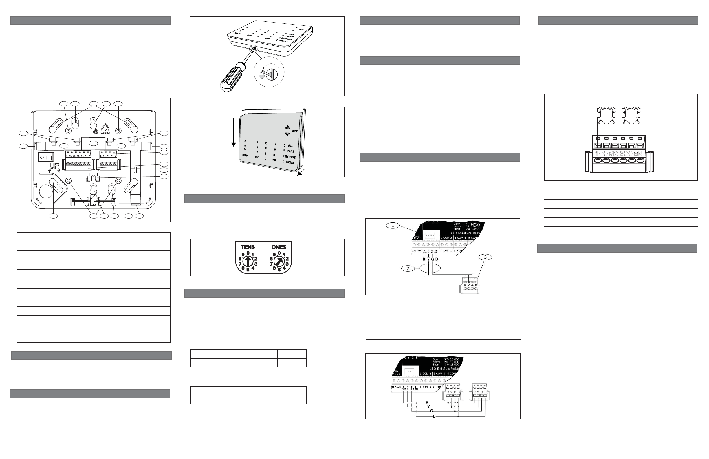
To wire detection devices to the B921C inputs, connect them
to the keypad terminals labeled for 1, 2, 3, 4, and COM. Wire
resistance on each sensor loop must be less than 100 with
the detection devices connected. The terminal strip supports 12
to 22 AWG (0.65 to 2 mm) wires.
The keypad detects open, short, normal, and ground fault circuit
conditions on its sensor loops and transmits the conditions to
the control panel. Each sensor loop is assigned a point number
and transmits to the control panel individually. Run wires away
from the premises telephone and AC wiring. Refer to Figure 3.3.
1COM2 3COM4
Figure 3.3: Wiring sensor loops
Callout Description
1 Keypad’s COM 1, 2, 3, and 4 terminal strip
2 Keypad sensor loops
31 k EOL resistor (ICP-1K22AWG-10)
4 Wiring to additional sensor loops
4 | Display
You can adjust the keypad’s display brightness level, and you
can turn the keypad’s nightlight feature on or off.
Adjusting the keypad display brightness:
1. Press [MENU] to open the Main menu.
2. Use [NEXT] to go to the Press 5 for Settings Menu option,
or simply press [5].
3. Use [NEXT] to go to the Press 4 for Keypad Confi g option,
or simply press [4].
4. Press [1] to adjust the brightness.
5. Use [PREV] or [NEXT] to adjust the brightness level. The
changes apply immediately.
6. Press [ESC] to exit the menu.
Turning the keypad nightlight on or off:
1. Press [MENU] to open the Main menu.
2. Use [NEXT] to go to the Press 5 for Settings Menu option,
or simply press [5].
3. Use [NEXT] to go to the Press 4 for Keypad Confi g option,
or simply press [4].
4. Use [NEXT] to go to the Press 4 for Nightlight option, or
simply press [4].
5. Press [ENTER] to turn it on or off. The changes apply
immediately.
6. Press [ESC] to exit the menu.
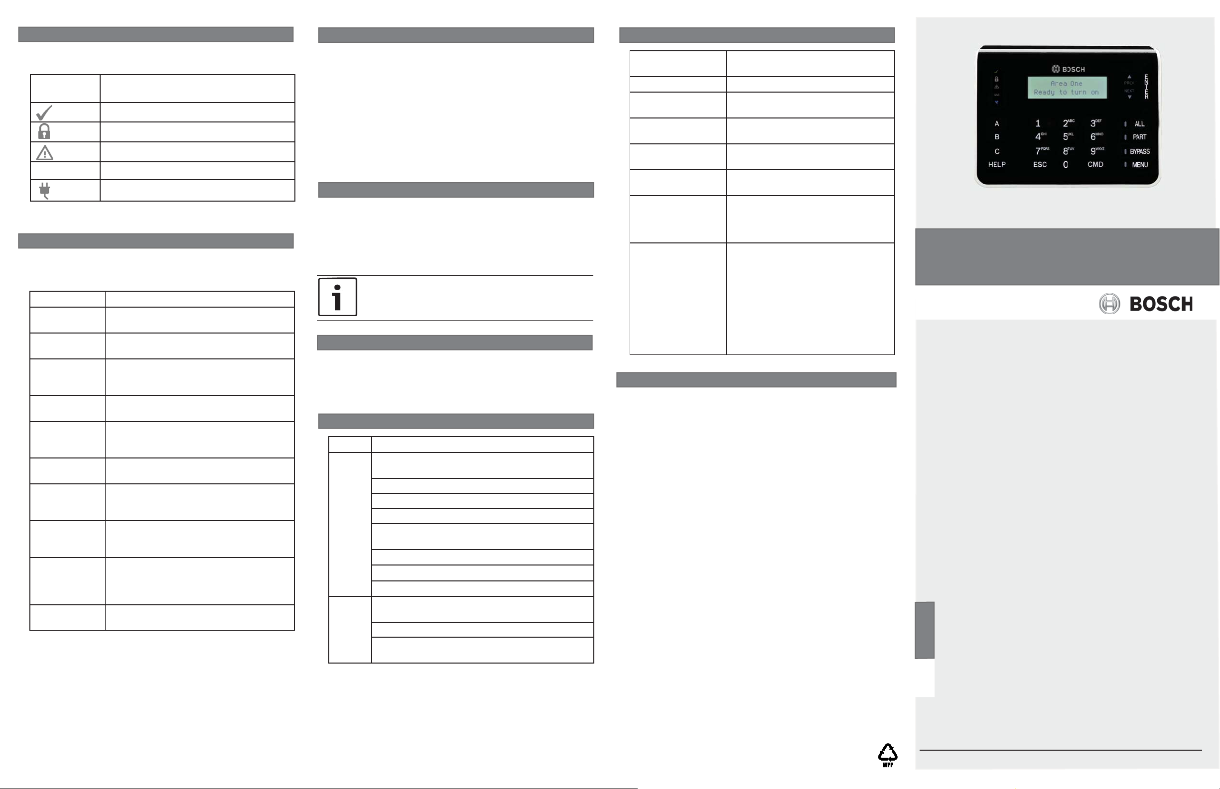
5 | Status indicators
7 | Supervision
11 | Specifi cations
You can diagnose and troubleshoot the system using the
keypad’s status indicators. Refer to Table 5.1.
Status
Function LED On
indicator
Ready to turn on (arm)
Turned on (armed)
System trouble
GAS
Table 5.1: Keypad status indicators
Gas alarm
AC power present
6 | Audible tones
The keypad has a built-in speaker that produces several distinct
warning tones. The keypad backlight illuminates when it emits
an audible tone.
Tone Description
Fire alarm When an area is in fi re alarm, the keypad
emits a pulsed, high-pitched bell tone.
Gas alarm When a gas point activates, the keypad
emits a unique high pitched tone.
User alarm When a user alarm (such as panic and
medical alarms) occurs, the tone sounds
for the programmed amount of time.
Burglary alarm When an area is in alarm, the keypad
emits a steady, high pitched bell tone.
Entry delay The keypad emits an intermittent beep
tone during entry delay periods to remind
the user to disarm the area.
Exit delay The keypad emits an intermittent beep
tone during exit delay.
Invalid button
buzz
Keypress The keypad emits a muted beep tone as
Trouble When a trouble event occurs, such as a
Watch point
fault
Table 6.1: Keypad audible tones
When an invalid button, or sequence of
buttons, is pressed, the keypad emits a
fl at buzz tone.
each button is pressed to indicate that
the entry was accepted.
service alert, the keypad emits a two-tone
warble until you enter a programmed
passcode with the appropriate authority.
A single clean tweedle tone alerts the
user anytime a watch point is faulted.
The control panel supervises all keypads on the SDI2 bus.
If a supervised keypad fails to respond to the control panel,
the control panel declares a Missing Keypad Trouble. When
the control panel can again communicate with the keypad,
it restores the Missing Keypad Trouble. During a Missing
Keypad Trouble, any connected keypad that maintained
contact with the control panel shows the Missing Keypad
Trouble as its idle text, and shows the missing keypad’s
address. The communicating keypads also sound a trouble
tone. Users can silence the trouble tone. If no other troubles
exist, the tone silences when the missing keypad restores.
8 | Show the fi rmware version
Showing the keypad fi rmware version:
1. Remove the keypad from the base to remove power to the
keypad. Refer to Figures 2.1 and 2.2.
2. Return the keypad to the base to restore power.
The keypad shows the
fi rmware version for 10 seconds.
NOTICE!
You can also view a keypad’s fi rmware version in RPS.
model number, keypad address, and
9 | Cleaning the keypad
Use a soft cloth and non-abrasive cleaning solution to clean your
keypad (for example, microfi ber cloth and eyeglass cleaner).
Spray the cleaner onto the cloth. Do not spray cleaners directly
onto the keypad.
10 | Certifi cations
Region Certifi cation
US UL 365 - Police Station Connected Burglar Alarm
Units and Systems
UL 609 - Local Burglar Alarm Units and Systems
UL 985 - Household Fire Warning System Units
UL 1023 - Household Burglar-Alarm System Units
UL 1076 - Proprietary Burglar Alarm Units and
Systems
UL 1610 - Central Station Burglar Alarm Units
CSFM - California Offi ce of The State Fire Marshal
FCC Part 15 Class B
Canada ULC-ORD C1076 - Proprietary Burglar Alarm Units
and Systems
ICES-003 - Digital Apparatus
ULC S545 - Residential Fire Warning System
Control Units
Dimensions 6.2 in x 4.7 in x 1 in (158 mm x 120
mm x 26 mm)
Voltage (input) 12 VDC nominal
Current 45 mA in standby mode
85 mA in alarm mode
Operating
temperature
Relative humidity 5% to 93% at +32°C (+90°F) non-
Terminal wire size 12 AWG to 22 AWG (2 mm to
SDI2 wiring Maximum distance - wire size
Compatibility B9512G/B9512G-E
Copyright
This document is the intellectual property of Bosch Security
Systems, Inc. and is protected by copyright. All rights reserved.
Trademarks
All hardware and software product names used in this document
are likely to be registered trademarks and must be treated
accordingly.
Bosch Security Systems, Inc. product manufacturing dates
Use the serial number located on the product label and refer to
the Bosch Security Systems, Inc. website at
http://www.boschsecurity.com/datecodes/.
0°C to +50°C (+32°F to +122°F)
condensing
0.65 mm)
(unshielded wire only):
700 ft (213 m) - 22 AWG (0.65 mm)
1000 ft (305 m) - 18 AWG (1.02 mm)
B8512G/B8512G-E
B5512
B4512
B3512
D9412GV4 version 2.0 or higher
D7412GV4 version 2.0 or higher
(Refer to the control panel
installation document for number of
supported devices.)
Two-line Capactive Keypad
B921C
en Installation Guide
Bosch Security Systems, Inc.
130 Perinton Parkway
Fairport, NY 14450
USA
www.boschsecurity.com
© 2015 Bosch Security Systems, Inc. F.01U.297.887 | 07 | 2015.02
 Loading...