

Bosch B443 Installation Manual
1 | Overview
2
3
4
5
6
1
1
The B443 provides IP communication over the GSM (GPRS/
EDGE/UMTS/HSPA+) digital cellular network by directly
connecting the module to the control panel. The control panel
can be configured to use B443 for alarm reporting, remote
access and personal notification messaging.
The B443 module requires a SIM card with active cellular
service to communicate. Bosch Cellular service and SIM
cards are available in some countries. Consult your Bosch
representative for details.
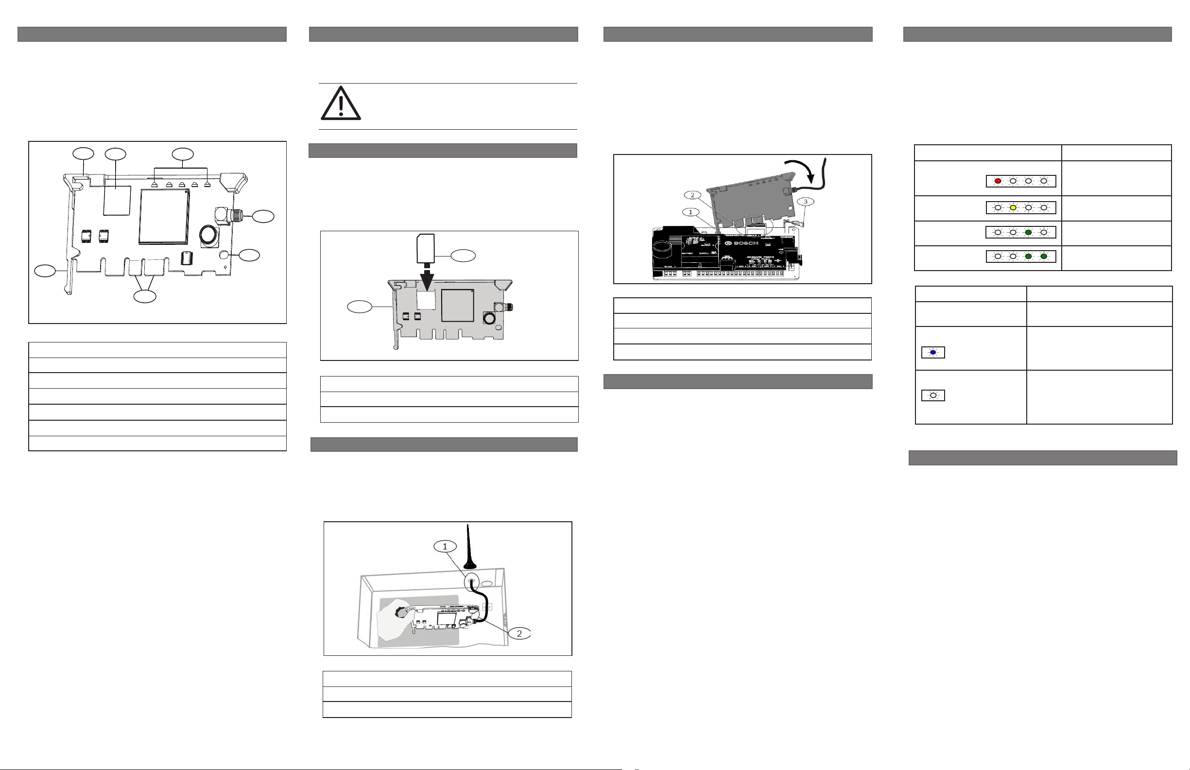
Figure 1.1: Board overview
Callout ― Description
1 ― Module handle and support leg
2 ― SIM card holder
3 ― LEDs
4 ―
Threaded female SMA antenna connector
5 ― Plug-in module retention clip opening
6 ― PCB metal contacts
2 | Installation and removal
If installing the communicator into a B450 module, refer to the
Conettix Plug-in Communicator Interface (B450) Installation and
Operation Guide for more information.
CAUTION!
Remove power to the control panel prior to installing
or removing the module.
2.1 | Insert the SIM card
Inserting the SIM card:
1. Break away the SIM card from the plastic die-cut card.
2. Insert the SIM card into the SIM card holder on the module
by sliding it into the card holder, verifying that the gold
contact side of the SIM card is against the module. Refer to
Figure 2.1.
2
1
Figure 2.1: Inserting the SIM card
Callout ― Description
1 ― Module
2 ― SIM card
2.2 | Install the antenna
Installing the antenna:
1. Place the magnetic antenna on top of the enclosure, or
vertically on another metal surface.
2. Route the antenna cable through a knockout.
3. Connect the antenna cable to the module.
4. Secure the antenna cable to the inside of the enclosure.
2.3 | Install the module
The control panel communicates with and provides power to the
module through the plug-in connection. Proper installation
results in the necessary electrical and mechanical connection.
Installing the module:
1. With the module facing the control panel as shown in Figure
2.3, insert the support leg into the support hole labeled X.
2. Align the PCB metal contacts with the on-board connector.
3. Push the module into place. The retention clip snaps closed
and secures the module in place.
Figure 2.3: Installing the module
Callout ― Description
1 ― Support leg
2 ― PCB metal contacts
3 ― Plug-in module retention clip
2.4 | Module removal
To remove an installed module, hold the plug-in module
retention clip open with one hand while grasping the top corners
of the module support handle with your other hand. Pull the
module out.
3 | Diagnostic LED descriptions
At power up, all module LEDs activate for several seconds,
indicating proper insertion. The Signal LEDs then turn off until
the module registers on the cellular network. Registering a new
module might take up to 3 minutes.
Check the LED display to ensure a good signal strength level,
and adjust the antenna location as required. The signal strength
LEDs momentarily turn off to indicate the module has measured
and updated the signal strength status. Refer to Table 3.1.
Flash pattern Function
Red Indicates an
unacceptable signal
strength level.
Yellow Indicates a marginal
signal strength level.
Green (1 light) Indicates a good signal
strength level.
Green (2 lights) Indicates a very good
signal strength level.
Table 3.1: Signal strength LEDs description
Flash pattern Function
Flashes once every 1
sec (blue)
On Steady (blue)
Off
Table 3.2: STATUS LED descriptions
4 |
Configuration
The programming of B443 Plug-in Communicators is be done
through the compatible control panel or the B450 Plug-in Communicator Interface. Refer to your control panel guide, remote
programming software help or the B450 IOG for parameter
descriptions, options and defaults.
status and management, use RPS or the online service portal
(go to http://www.conettix.com/Cellular.aspx and click on
the Cellular Portal Login link).
Normal State. Indicates normal
operation.
Communication Error State.
Indicates the module is unable
to communicate on the cellular
network.
LED Trouble State. Module is not
powered, or some other trouble
condition prohibits the module
from controlling the STATUS LED.
(Check for proper installation.)
For Bosch Cellular account
Configure network alarm communication routes and settings
in the control panel. Cellular carrier specific settings such
as Access Point Name and SIM card security can also be
programmed through control panel or Conettix Plug-in
Figure 2.2: Installing the antenna
Callout ― Description
1 ― Antenna routed through any knockout
2 ― Antenna cable connected to the module
Communicator Interface (B450).
5 |
Certifications
Region Agency Certification
US FCC FCC, Part 15 Class B Radiated/
Conducted Emissions
UL UL 365 - Police Station Connected
Burglar Alarm Units and Systems
UL 636 - Holdup Alarm Units and
Systems
UL 864 - Standard for Control Units and
Accessories for Fire Alarm Systems
UL 985 - Household Fire Warning System
Units
UL 1023 - Household Burglar-Alarm
System Units
UL 1076 - Proprietary Burglar Alarm
Units and Systems
UL 1610 - Central-Station Burglar-Alarm
Units
Canada ULC ULC C1023 - Household Burglar Alarm
System Units
ULC C1076 - Proprietary Burglar Alarm
Units and Systems
ULC S303 - Local Burglar Alarm Units
and System
ULC S304 - Central and Monitoring
Station Burglar Alarm Units
ULC S545 - Residential Fire Warning
System Control Units
IC ICES-003
Rogers Certified
North
America
Europe CE Hereby, Bosch, declares that this plug-in
PTCRB Certified
communicator is in compliance with
the essential requirements and other
relevant provisions of Directive 1999/5/
EC.
6 | Specifications
Dimensions 50 mm x 93.5 mm x 15.25 mm
(2 in x 3.68 in x 0.60 in)
Voltage (operating) 12 V nominal
Standby current 60 mA
Maximum current 150 mA
Operating temperature 0°C to +49°C (+32°F to +120°F)
Relative humidity Up to 93% non-condensing
Cellular compatibility 4 Bands GPRS/EDGE:
850/900/1800/1900 MHz
5 Bands UMTS/
HSPA: 800/850/900/
AWS1700/1900/2100 MHz
SIM card 3V/1.8V SIM (compliant with
GSM 11.12 recommendation)
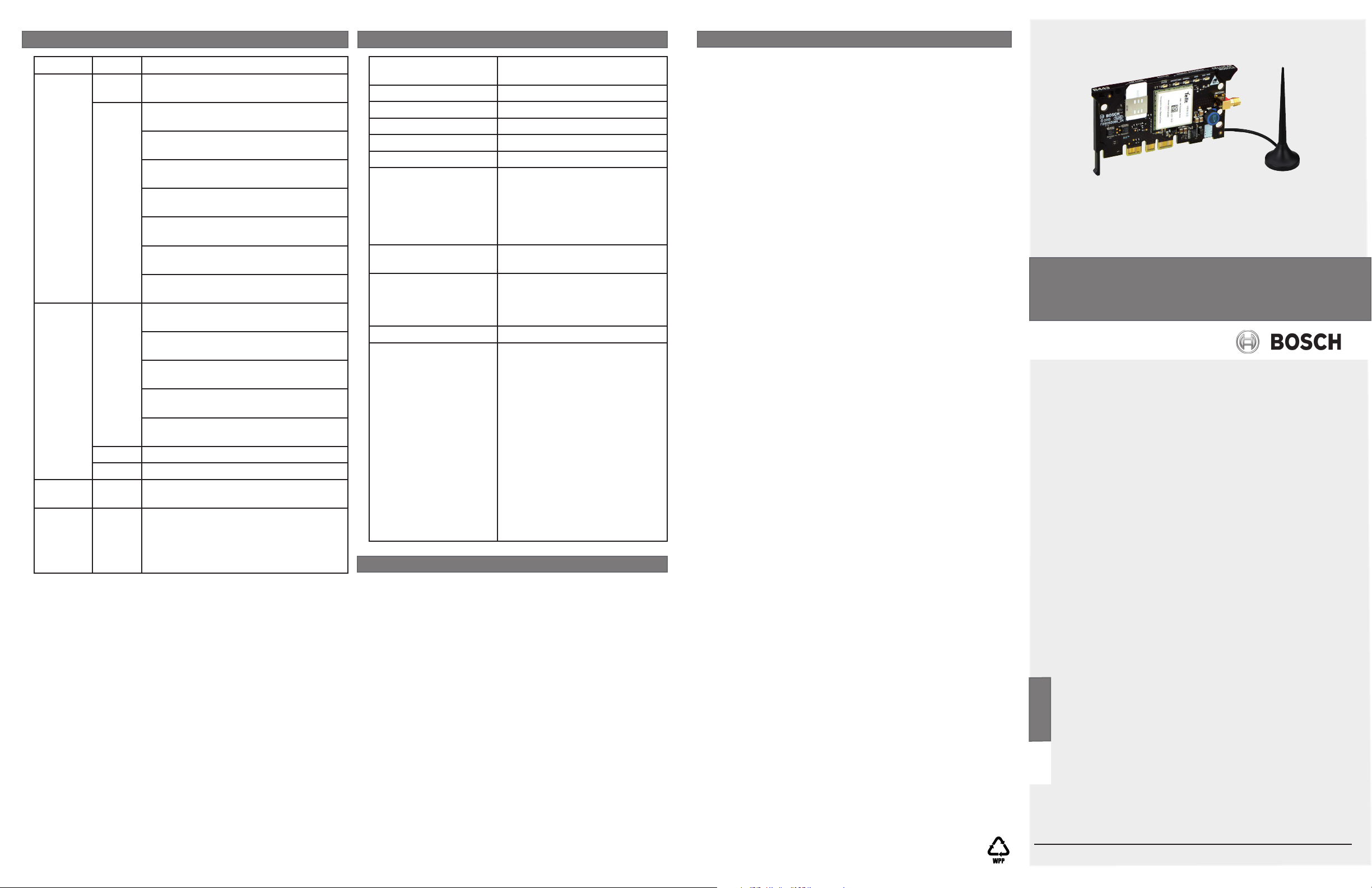
Included antenna – Magnetic base omni-directional
antenna
– 2.5 m (8.2 ft) cable with SMA
connector
Environmental Indoor usage only
Compatibility Control panels
B9512G/B9512G-E
B8512G/B8512G-E
B5512/B5512E
B4512/B4512E
B3512/B3512E
The B443 is compatible with
most Bosch control panels
when used with a B450 Conettix
Plug-in Communicator Interface.
Refer to the Conettix Plug-in
Communicator Interface (B450)
Installation and Operation Guide
for complete control panel
compatibility listings.
Copyright
This document is the intellectual property of Bosch Security
Systems, Inc. and is protected by copyright. All rights reserved.
Trademarks
All hardware and software product names used in this document
are likely to be registered trademarks and must be treated
accordingly.
Bosch Security Systems, Inc. product manufacturing dates
Use the serial number located on the product label and refer to
the Bosch Security Systems, Inc. website at
http://www.boschsecurity.com/datecodes/.
English
Hereby, Bosch Security Systems, declares that this intrusion
detector is in compliance with the essential requirements and
other relevant provisions of Directive 1999/5/EC.
Finnish
Bosch Security Systems vakuuttaa täten että rikosilmoitin
tyyppinen laite on direktiivin 1999/5/EY oleellisten vaatimusten ja sitä koskevien direktiivin muiden ehtojen mukainen.
Dutch
Hierbij verklaart Bosch Security Systems dat het toestel inbraakdetector in overeenstemming is met de essentiële eisen
en de andere relevante bepalingen van richtlijn 1999/5/EG.
Bij deze verklaart Bosch Security Systems dat deze inbraakdetector voldoet aan de essentiële eisen en aan de overige
relevante bepalingen van Richtlijn 1999/5/EC.
French
Par la présente Bosch Security Systems déclare que l’appareil
détecteur d’intrusion est conforme aux exigences essentielles
et aux autres dispositions pertinentes de la directive 1999/5/
CE. Par la présente, Bosch Security Systems déclare que ce
détecteur d’intrusion est conforme aux exigences essentielles
et aux autres dispositions de la directive 1999/5/CE qui lui
sont applicables.
Swedish
Härmed intygar Bosch Säkerhetssystem att denna inbrottsdetektor står I överensstämmelse med de väsentliga egenskapskrav och övriga relevanta bestämmelser som framgår av
direktiv 1999/5/EG.
Danish
Undertegnede Bosch sikkerhedssystemer erklærer herved, at
følgende udstyr Indbrudsdetektor overholder de væsentlige
krav og øvrige relevante krav i direktiv 1999/5/EF.
German
Hiermit erklärt Bosch Sicherheitssysteme, dass sich dieser/
diese/dieses Einbruchmelder in Übereinstimmung mit den
grundlegenden Anforderungen und den anderen relevanten
Vorschriften der Richtlinie 1999/5/EG befindet”. (BMWi).
Hiermit erklärt Bosch Sicherheitssysteme die Übereinstimmung des Gerätes Einbruchmelder mit den grundlegenden
Anforderungen und den anderen relevanten Festlegungen der
Richtlinie 1999/5/EG. (Wien).
Greek
ΜΕ ΤΗΝ ΠΑΡΟΥΣΑ Συστήματα ασφαλείας Bosch ΔΗΛΩΝΕΙ ΟΤΙ
Ανιχνευτής εισβολής ΣΥΜΜΟΡΦΩΝΕΤΑΙ ΠΡΟΣ ΤΙΣ ΟΥΣΙΩΔΕΙΣ
ΑΠΑΙΤΗΣΕΙΣ ΚΑΙ ΤΙΣ ΛΟΙΠΕΣ ΣΧΕΤΙΚΕΣ ΔΙΑΤΑΞΕΙΣ ΤΗΣ
ΟΔΗΓΙΑΣ 1999/5/ΕΚ.
Italian
Con la presente Bosch Security Systems dichiara che questo
rilevatore antintrusione è conforme ai requisiti essenziali
ed alle altre disposizioni pertinenti stabilite dalla direttiva
1999/5/CE.
Spanish
Por medio de la presente Bosch Security Systems declara
que el detector de intrusión cumple con los requisitos esenciales y cualesquiera otras disposiciones aplicables o exigibles
de la Directiva 1999/5/CE.
Portuguese
Bosch Security Systems declara que este detector de intrusão está conforme com os requisitos essenciais e outras
disposições da Directiva 1999/5/CE.
Conettix Plug-in HSPA+ Cellular
Communicator
B443
en Installation Guide
Bosch Security Systems, Inc.
130 Perinton Parkway
Fairport, NY 14450
USA
www.boschsecurity.com
Bosch Sicherheitssysteme GmbH
Robert-Bosch-Ring 5
85630 Grasbrunn
Germany
© 2015 Bosch Security Systems, Inc. F.01U.299.718 | 07 | 2015.05
 Loading...