

Bosch B441, B440 Installation Manual
At power up, all B441 LEDs activate for
several seconds, indicating proper insertion.
The Signal LEDs then turn off until the
module registers on the cellular network.
Registering a new module might take up to 2
minutes.
Check the LED display to ensure a good
signal strength level, and adjust the antenna
location as required. The signal strength
LEDs momentarily turn off to indicate the
module has measured and updated the signal
strength status. Refer to Table 3.1.
3 | Diagnostic LED
descriptions
The B441 provides IP communication over the Verizon cellular network by directly connecting the
module to the control panel. The control panel can be confi gured for IP alarm reporting, remote
access, or personal notifi cation messages over the cellular network.
The B441 module requires active cellular service to communicate. Bosch Cellular devices are
shipped pre-activated with Bosch Cellular service.
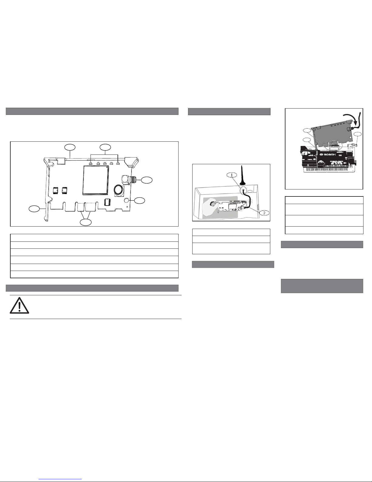
Callout ― Description
1 ― Module handle and support leg
2 ― LEDs
3 ―
Threaded female SMA antenna connector
4 ― Plug-in module retention clip opening
5 ― PCB metal contacts
Figure 1.1: Module overview
CAUTION!
Remove all power (AC and battery) before making any connections. Failure to do so
might result in personal injury and/or equipment damage.
2 | Install or remove the module
1 | Overview
1
2
3
4
5
1
2.1 | Install the antenna
Installing the antenna:
1. Place the magnetic antenna on top of
the enclosure, or vertically on another
metal surface.
2. Route the antenna cable through a
knock-out.
3. Connect the antenna cable to the
module.
4. Secure the antenna cable to the inside
of the enclosure.
Figure 2.2: Wiring the antenna
Callout ― Description
1 ― Antenna routed though any knock-out
2 ― Antenna cable connected to the
module
To remove an installed module, hold the plugin module retention clip open with one hand
while grasping the top corners of the module
support handle with your other hand. Pull
the module out.
2.3 | Remove the module
Installing the module:
1. With the module facing the control
panel as shown below, insert the
support leg into the support hole
labeled X.
2. Align the PCB metal contacts with the
on-board connector.
3. Push the module into place. The
retention clip snaps closed and secures
the module in place.
1
3
2
Figure 2.2: Module installation
Callout ― Description
1 ― Support leg inserted into the control
panel support hole labeled X
2 ― PCB metal contacts resting on the
on-board connector
3 ― Plug-in module retention clip
2.2 | Install the module
The control panel communicates with and
provides power to the module through the
plug-in connection. Proper installation results
in the necessary electrical and mechanical
connection.
© 2015 Bosch Security Systems, Inc.
F.01U.282.233 | 05 | 2015.05
en Installation Guide
Conettix Plug-in CDMA
Bosch Security Systems, Inc.
130 Perinton Parkway
Fairport, NY 14450
USA
www.boschsecurity.com
Cellular Communicator
B441
Bosch Sicherheitssysteme
GmbH
Robert-Bosch-Ring 5
85630 Grasbrunn
Germany
6 | Specifi cations
Region Agency Certifi cation
US FCC FCC, Part 15 Class B Radiated/Conducted Emissions
Verizon Open Development Certifi ed
UL UL 365 - Police Station Connected Burglar Alarm Units and
Systems
UL 636 - Holdup Alarm Units and Systems
UL 864 - Control Units and Accessories for Fire Alarm Systems
UL 985 - Household Fire Warning System Units
UL 1023 - Household Burglar-Alarm System Units
UL 1076 - Proprietary Burglar Alarm Units and Systems
UL 1610 - Central-Station Burglar-Alarm Units
Dimensions 2 in x 3.68 in x 0.60 in (50 mm x 93.5 mm x 15.25 mm)
Voltage (operating) 12 V nominal
Standby current 35 mA
Alarm current 100 mA
Operating temperature 0°C to +49°C (+32°F to +120°F)
Relative humidity Up to to 93% non-condensing
Cellular compatibility CDMA2000
1xRTT
Included antenna – Magnetic base omni-directional antenna
– 2.5 m (8.2 ft) cable with SMA connector
Compatibility Control Panels
B9512G/B9512G-E/B8512G/B8512G-E
B5512/B5512E, B4512/B4512E, B3512/B3512E
The B441 is compatible with most Bosch control panels when
used with a B450 Conettix Plug-in Communicator Interface.
Refer to the Conettix Plug-in Communicator Interface (B450)
Installation and Operation Guide for complete control panel
compatibility listings.
Copyright
This document is the intellectual property of Bosch Security Systems, Inc. and is protected by
copyright. All rights reserved.
Trademarks
All hardware and software product names used in this document are likely to be registered
trademarks and must be treated accordingly.
Bosch Security Systems, Inc. product manufacturing dates
Use the serial number located on the product label and refer to the Bosch Security Systems, Inc.
website at
http://www.boschsecurity.com/datecodes/.
Use Remote Programming Software (RPS) or
an SDI2 keypad to program the control panel to
use the module for communication.
For programming parameter descriptions,
options, and defaults refer to RPS Help or the
Program Entry Guide for your control panel.
For Bosch Cellular account status and
management, use RPS or the online service
portal (go to http://www.conettix.com/
Cellular.aspx and click on the Cellular Portal
Login link).
5 | Certifi cations
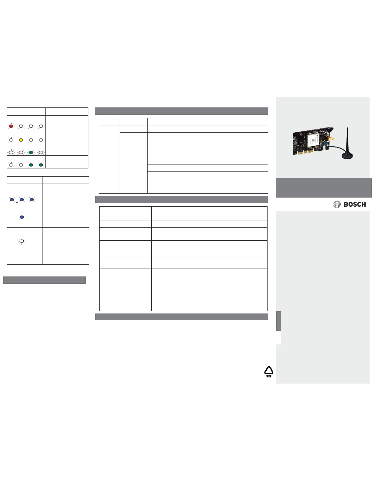
Flash pattern Function
Red Indicates an
unacceptable signal
strength level.
Yellow Indicates a marginal
signal strength level.
Green (1 light) Indicates a good
signal strength level.
Green (2 lights) Indicates a very good
signal strength level.
Table 3.1: Signal strength LEDs description
Flash pattern Function
Flashes once every 1 sec (blue)
Normal State: Indicates
normal operation.
ON Steady (blue)
Communication Error
State: Indicates the
module is unable to
communicate on the
cellular network.
OFF Steady
LED Trouble State:
Module is not powered,
or some other trouble
condition prohibits
the module from
controlling the STATUS
LED. (Check for proper
installation.)
Table 3.2: STATUS LED descriptions
4 | Confi guration
 Loading...