

Bosch AMC-4W Installation Manual
EN
Access Controller
AMC-4W
Bosch Security Systems | V.3.1/2006-09

Trademarks Access Controller AMC-4W
2 Installation Guide Bosch Security Systems | V.3.1/2006-09
Trademarks
Bosch is a registered trademark of Bosch Security Systems in the United States
and/or other countries.
Remarks
This hardware is part of a security system. Access shall be limited to
authorized persons only.
Some states do not allow the exclusion or limitation of implied warranties, or
limitation of liability for incidental or consequential damages, so the above
limitation or exclusion might not apply to you.
Bosch Security Systems retains all rights not expressly granted. Nothing in this
license constitutes a waiver of Bosch’s rights under the U.S. Copyright laws or
any other federal or state law.
If you have any questions concerning this license, please, write to:
Bosch Access Systems GmbH
Adenauerstr. 20 / A3
D-52146 Würselen
Germany.

Access Controller AMC-4W Contents
Bosch Security Systems | V.3.1/2006-09 Installation Guide 3
Contents
1. Please, read the following notes carefully.........................................5
1.1. Explanation of Used Symbols ..............................................................5
1.2. Internet.................................................................................................. 5
1.3. We Are Interested in Your Opinion...................................................... 5
2. Safety Instructions..............................................................................6
2.1. Important Safety Notes......................................................................... 6
2.2. FCC & ICES Information..................................................................... 8
2.3. Safety Precautions ................................................................................ 9
2.4. Unpacking ..........................................................................................10
3. Description of the AMC-4W............................................................11
3.1. Equipment Configuration ................................................................... 13
3.2. Performance Characteristics ...............................................................16
3.3. System Overview................................................................................ 17
4. Technical Data..................................................................................18
5. Installing the AMC-4W....................................................................21
5.1. Mounting the AMC-4W .....................................................................21
5.1.1. Mounting on rails ............................................................................... 21
5.1.2. Demounting the AMC-4W from mounting rails ................................ 21
5.2. Opening the AMC-4W Case............................................................... 22
5.3. Cabling ...............................................................................................22
5.4. Grounding and Shielding.................................................................... 23
5.5. Connecting Power Supply ..................................................................25
5.6. RS485 Host Interface..........................................................................27
5.6.1. RS485 Two Wire Connection.............................................................28
5.6.2. RS485 Four Wire Connection ............................................................ 29
5.6.3. DIL Switch Address Selector .............................................................30
5.7. RS232 Host Interface..........................................................................32
5.8. Ethernet Interface ...............................................................................33
5.8.1. Removing Ethernet Plugs from Socket............................................... 33
5.9. RS485 Extension Module Bus............................................................ 34
5.10. Wiegand Interface for Card Readers ..................................................35
5.11. Connecting Relay Outputs.................................................................. 36

Contents Access Controller AMC-4W
4 Installation Guide Bosch Security Systems | V.3.1/2006-09
5.12. Connecting Analog Input Devices...................................................... 38
5.13. Tamper Protection .............................................................................. 40
6. Operating the AMC-4W ..................................................................41
6.1. Status Display of the AMC-4W.......................................................... 41
6.2. Configuring the Ethernet Interface..................................................... 42
6.3. Resetting the AMC-4W...................................................................... 42
7. Appendix...........................................................................................44
7.1. Connecting Diagrams ......................................................................... 44
7.2. Jumpers............................................................................................... 48
7.3. Proprietary burglar alarm/access control power supply .............Fehler!
Textmarke nicht definiert.
7.3.1. Overview ......................................Fehler! Textmarke nicht definiert.
7.3.2. Power Supply Voltage Output Selections..... Fehler! Textmarke nicht
definiert.
7.3.3. LED Diagnostics ..........................Fehler! Textmarke nicht definiert.
7.3.4. Installation Instructions for the RK-AL600ULX-4CB6 .............Fehler!
Textmarke nicht definiert.
7.4. Legend................................................................................................ 50
7.5. Product declaration............................................................................. 51
7.6. Listings and Approvals....................................................................... 51
7.6.1. FCC Notice......................................................................................... 51
7.6.2. UL Listing .......................................................................................... 51
7.6.3. Safety.................................................................................................. 51
7.7. Included in delivery............................................................................ 51
8. List of Figures...................................................................................52
9. Index..................................................................................................54
Access Controller AMC-4W Please read the following notes carefully
Bosch Security Systems | V.3.1/2006-09 Installation Guide 5
1. Please read the following notes carefully
1.1. Explanation of Used Symbols
Throughout this document, helpful tips, important notes, cautions and warnings
will be presented for the reader to keep in mind. These appear different from
the rest of the text as follows:
Caution!
These warn the operator that damage to the program or equipment
might occur.
Important Notes – must be followed for successful operation and
programming. Tips and shortcuts might also be included here.
Cross Reference
Please, refer to this document or chapter to obtain additional
information about the issue.
1.2. Internet
If you are interested in further information on this product or information on
other products, please, refer to our website at http://www.bosch-securitysystems.com.
1.3. We Are Interested in Your Opinion
We constantly improve the quality of our products and our manuals. Should
you have any suggestions for improvement, please, send us your comments.
Bosch Security Systems
Adenauerstr 20 / A3
D-52146 Würselen
Germany
Tel.: +49 24 05 / 60 05-0
Fax: +49 24 05 / 60 05-29
Email:
info.service@de.bosch.com

Safety Instructions Access Controller AMC-4W
6 Installation Guide Bosch Security Systems | V.3.1/2006-09
2. Safety Instructions
2.1. Important Safety Notes
1. Read, Follow, and Retain Instructions − All safety and operating
instructions must be read and followed properly before putting the unit into
operation. Retain instructions for future reference.
2. Consider all Warnings − Adhere to all warnings on the unit and in the
operating instructions.
3. Accessories − Use only accessories recommended by the manufacturer or
those sold with the product. Accessories not recommended by the
manufacturer shall not be used, as they may cause hazards.
4. Installation Precautions − Do not place this unit on an unstable stand,
tripod, bracket, or mount. The unit may fall, causing serious injury to
persons and damage to the unit. Mount the unit according to the
manufacturer’s instructions.
5. Cleaning − Disconnect the unit from power before cleaning. Follow any
instructions provided with the unit. Generally, using a damp cloth for
cleaning is sufficient. Do not use liquid cleaners or aerosol cleaners.
6. Service − Do not attempt to service this unit by yourself. Opening or
removing covers may expose you to dangerous voltages or other hazards.
Refer all servicing to qualified service personnel.
7. Damage Requiring Service − Disconnect the unit from the main AC or
DC power source and refer servicing to qualified service personnel under
the following conditions:
• When the power supply cord or plug is damaged.
• If liquid has been spilled or an object has fallen into the unit.
• If the unit has been exposed to water and/or inclement weather (rain,
snow, etc.).
• If the unit does not operate normally, when following the operating
instructions. Adjust only those controls specified in the operating
instructions. Improper adjustment of other controls may result in
damage, and require extensive work by a qualified technician to
restore the unit to normal operation.
• If the unit has been dropped or the cabinet damaged.
• If the unit exhibits a distinct change in performance, this indicates that
service is needed.

Access Controller AMC-4W Safety Instructions
Bosch Security Systems | V.3.1/2006-09 Installation Guide 7
8. Replacement Parts − When replacement parts are required, the service
technician shall use replacement parts that are specified by the
manufacturer. Unauthorized substitutions may result in fire, electrical
shock or other hazards.
9. Safety Check − Upon completion of service or repair work on the unit, ask
the service technician to perform safety checks to ensure that the unit
operates properly
10. Power Sources − Operate the unit only from the type of power source
indicated on the label. If unsure of the type of power supply to use, contact
your dealer
• For units intended to operate from battery power, refer to the operating
instructions.
• For units intended to operate with External Power Supplies, use only
the recommended approved power supplies.
• For units intended to operate with a limited power source, this power
source must comply with EN/UL 60950. Substitutions may damage
the unit or cause fire or shock.
• For units intended to operate at 12 VDC normal input voltage is 12
VDC. Voltages applied to the unit’s power input shall not exceed 15
VDC. User-supplied wiring, from the 12 VDC power supply to the
unit, must be in compliance with electrical codes (Class 2 power
levels). Do not ground the 12 VDC supply at the terminals or at the
unit’s power supply terminals.
11. Grounding − If an outside cable system is connected to the unit, ensure
that the cable system is grounded. U.S.A. models only Section 810 of the
National Electrical Code, ANSI/ NFPA No.70, provides information
regarding proper grounding of the mount and supporting structure,
grounding of the coax to a discharge unit, size of grounding conductors,
location of discharge unit, connection to grounding electrodes, and
requirements for the grounding electrode.
12. Grounding and Protection against reverse Polarity − This unit may be
equipped with a polarized alternating current line plug (a plug with one
blade wider than the other). This safety feature allows the plug to fit into
the power outlet in only one way. If unable to insert the plug fully into the
outlet, try reversing the plug. If the plug still fails to fit, contact an
electrician to arrange replacement of the obsolete outlet. Do not defeat the
safety purpose of the polarized plug. Alternately, this unit may be equipped
with a 3−wire grounding plug (a plug with a third pin, for grounding). This
safety feature allows the plug to fit into a grounding power outlet only. If
unable to insert the plug into the outlet, contact an electrician to arrange

Safety Instructions Access Controller AMC-4W
8 Installation Guide Bosch Security Systems | V.3.1/2006-09
replacement of the obsolete outlet. Do not defeat the safety purpose of the
grounding plug.
13. Lightning − For added protection during a lightning storm, or when this
unit is left unused for long periods of time, disconnect the unit from power.
This will prevent damage to the unit due to lightning and excessive power
line surges.
14. Restricted Access Locations are required for the installation.
2.2. FCC & ICES Information
This equipment generates and uses radio frequency energy. If not installed and
used in accordance with the manufacturer's instructions, it may cause
interference to radio and television reception. It has been tested and found to
comply with the specifications Subpart B of Part 15 of FCC rules for Field
Disturbance Sensors. If this equipment causes interference to radio or television
reception - which can be determined by turning the equipment on and off - the
installer is encouraged to correct the interference by one or more of the
following measures:
1. Reorient the antenna of the radio/television,
2. Connect the AC power cord to a different outlet so the control panel and
radio/television are on different branch circuits,
3. Relocate the control panel with respect to the radio/television.
If necessary, consult an experienced radio/television technician for additional
suggestions, or send for the "Interference Handbook" prepared by the Federal
Communications Commission. This booklet is available from the:
U.S. Government Printing Office,
Washington D.C. 20402,
Stock no. 004-000-00450-7.
FCC Registration Number: IDHM32Y6K2000
Intentional or unintentional changes or modifications that are not explicitly
approved by the party responsible for compliance, shall not be made. Any such
changes or modifications could nullify the user’s authority to operate the
equipment.
The user may find the following booklet, prepared by the Federal
Communications Commission, helpful: How to Identify and Resolve Radio-TV
Interference Problems. This booklet is available from the U.S. Government
Printing Office, Washington, DC 20402, Stock No. 004-000-00345-4.
Access Controller AMC-4W Safety Instructions
2.3. Safety Precautions
Read instructions!
Before working with the AMC-4W, read these instructions carefully.
Make sure you have understood all information described in this
document.
Warning! Risk of electric shock!
External power supplies must be installed and put into service by
qualified personnel. Compliance with the relevant regulations must be
ensured.
Warning! Risk of damaging equipment!
- Always switch off power of the AMC-4W before modifying
the installation.
- Do not connect or disconnect plug connectors, data cables or
screw connectors while power is on!
Health and Safety
Installation of the AMC-4W must comply with any local fire, health
and safety regulations. A secured door that may be part of an escape
route from an area must be installed with:
• A fail-safe lock (A). So that the door will be released if
power fails. Ideally, a magnetic lock should be used as these
are less likely to jam or seize.
• A normally-closed break-glass or manual pull (B) in the lock
supply wiring, so that in an emergency the fail-safe lock can
be immediately powered down.
You must ground the AMC-4W. Disconnect both AC and battery
power supply before working on the controller.
Bosch Security Systems | V.3.1/2006-09 Installation Guide 9
Safety Instructions Access Controller AMC-4W
10 Installation Guide Bosch Security Systems | V.3.1/2006-09
Warning! Risk of damage!
Protect the hardware from electrostatic discharge by observing ESD
instructions before unpacking or touching connectors or electronics.
CAUTION: Lithium Battery
Danger of explosion if battery is replaced incorrectly. Replace only
with the same type as recommended by the manufacturer. Dispose
used batteries according to the battery manufacturer’s instructions.
2.4. Unpacking
Check the packaging for visual damage. If anything has been damaged during
transport, make the transport agency aware of this.
Carefully unpack the unit. This is an electronic device that must be handled
with care to avoid damage. Do not attempt to put the unit into operation if
components are damaged.
If parts are missing, inform your customer service representative or a Bosch
Security Systems salesperson. The shipping carton is the safest transport
container for the unit. Store it and the other packaging material for future use. If
the unit has to be sent back, use the original packaging.
Access Controller AMC-4W Description of the AMC-4W
Bosch Security Systems | V.3.1/2006-09 Installation Guide 11
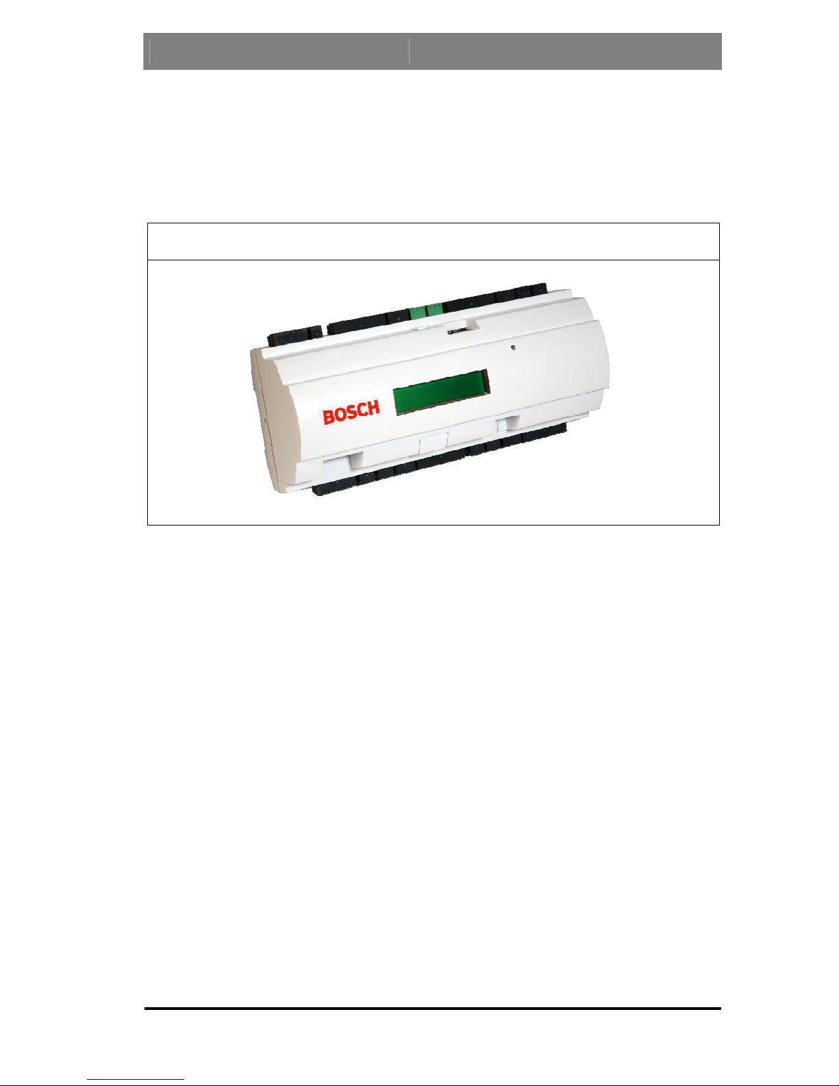
3. Description of the AMC-4W
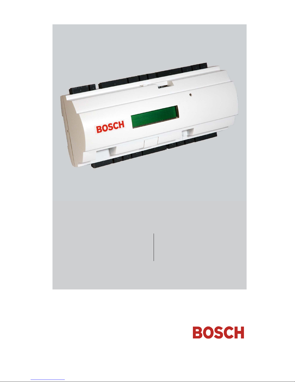
The AMC-4W is equipped with four independent interfaces for Wiegand type
readers. By that it is able to control two doors with a reader in each direction
and up to four doors with a reader in one direction only.
Figure 1: The Access Controller AMC-4W
All necessary information for access verification is stored in a battery buffered
on-board memory and a Compact Flash (CF) memory card. This guarantees
autonomous access decisions and complete access registrations even if the
management host system is offline. The built in compact flash adapter provides
adequate storage capability for cardholders and events, simply by exchanging
the standard compact flash card with 64 MB by one with 128 MB, 256 MB,
512 MB or 1 GB capacity.
Description of the AMC-4W Access Controller AMC-4W
12 Installation Guide Bosch Security Systems | V.3.1/2006-09
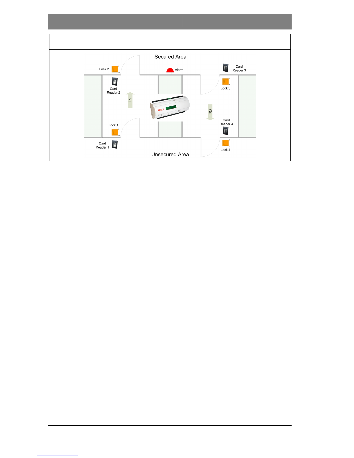
Figure 2: The AMC-4W in a four door safety lock
The AMC-4W can communicate upstream to the host computer via eight
RS485 multi-dropped, RS232 or 10/100 Mbit/s Ethernet. It has eight analog
input devices and eight relay outputs. With its analog input devices, the
AMC-4W verifies, for example, if a lock is closed or open. The relay outputs
can be used to activate lock mechanisms if access is granted, or activate an
external alarm system if an intrusion or system alert is detected.
The AMC-4W provides an IP protocol stack completely developed by Bosch.
There are no third party operating systems and there is no vulnerability by
viruses. The AMC-4W electronic is completely covered by a plastic housing.
The LC Display provides all important status information. The setup procedure
for an AMC-4W is very simple and extremely fast by the use of door templates.
Once selected, all the inputs and outputs are predefined.
Using the AMC-4W gives you the full functionality and the offline capability
of a complete access control system on each room. This leads to an excellent
reliability and a very high redundancy without paying extra money.
Access Controller AMC-4W Description of the AMC-4W
Bosch Security Systems | V.3.1/2006-09 Installation Guide 13
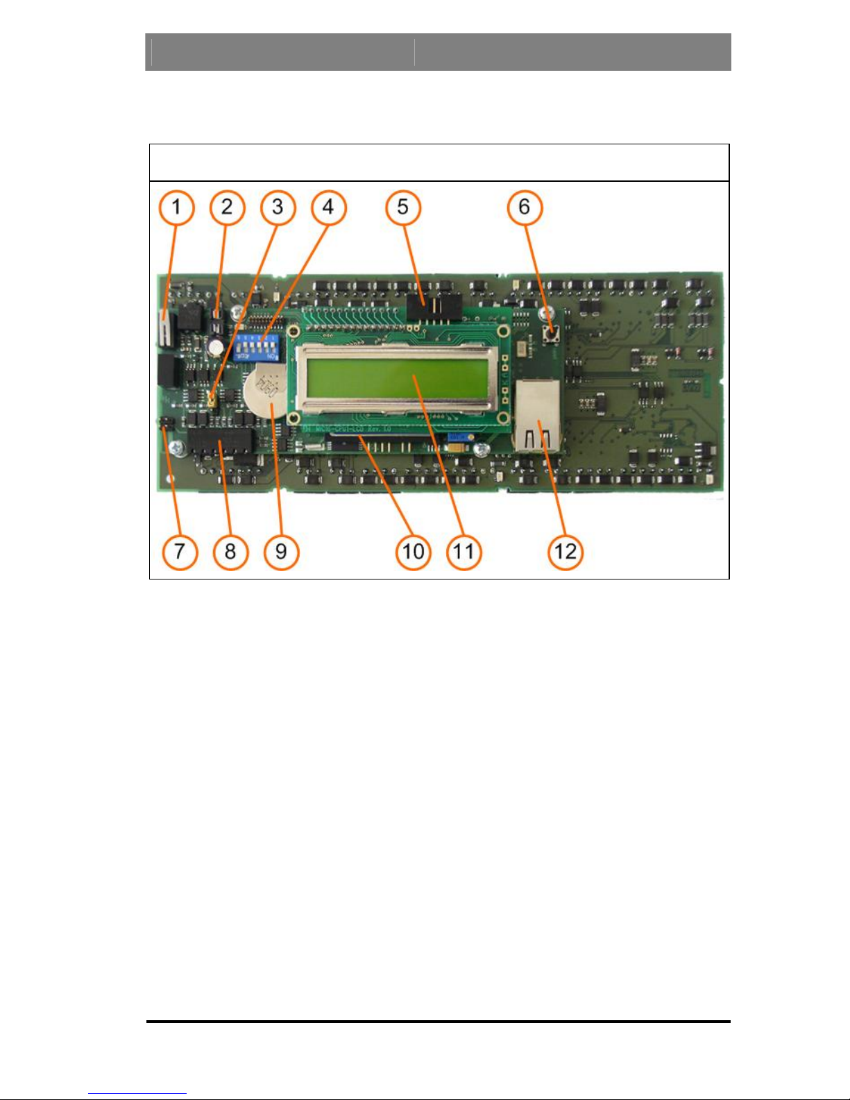
3.1. Equipment Configuration
Figure 3: Upper circuit board with display (top side)
1. Internal tamper contact
2. Fuseholder, not used in this application
3. Jumper: interface selector RS485 Host connection, RS485 two wire or
RS485 four wire (depends on external wiring)
4. DIL switch for RS485 address selection, protocol and RS232/RS485
selection
5. Configurable RS232 host interface (ribbon cable connector)
6. Reset push button
7. Jumper: Potential equalization between different mass systems and
protective earth (shield)
8. Configurable RS485 host interface (pluggable screw connector)
9. Lithium battery for buffering of static RAM and real time clock
(RTC). The battery shall be replaced by qualified personnel every ten
years or if indicated by an appropriate event.

Description of the AMC-4W Access Controller AMC-4W
14 Installation Guide Bosch Security Systems | V.3.1/2006-09
10. Compact Flash (optional size)
11. LC Display
12. Configurable 10/100 Mbit/s Ethernet interface
Access Controller AMC-4W Description of the AMC-4W
Bosch Security Systems | V.3.1/2006-09 Installation Guide 15
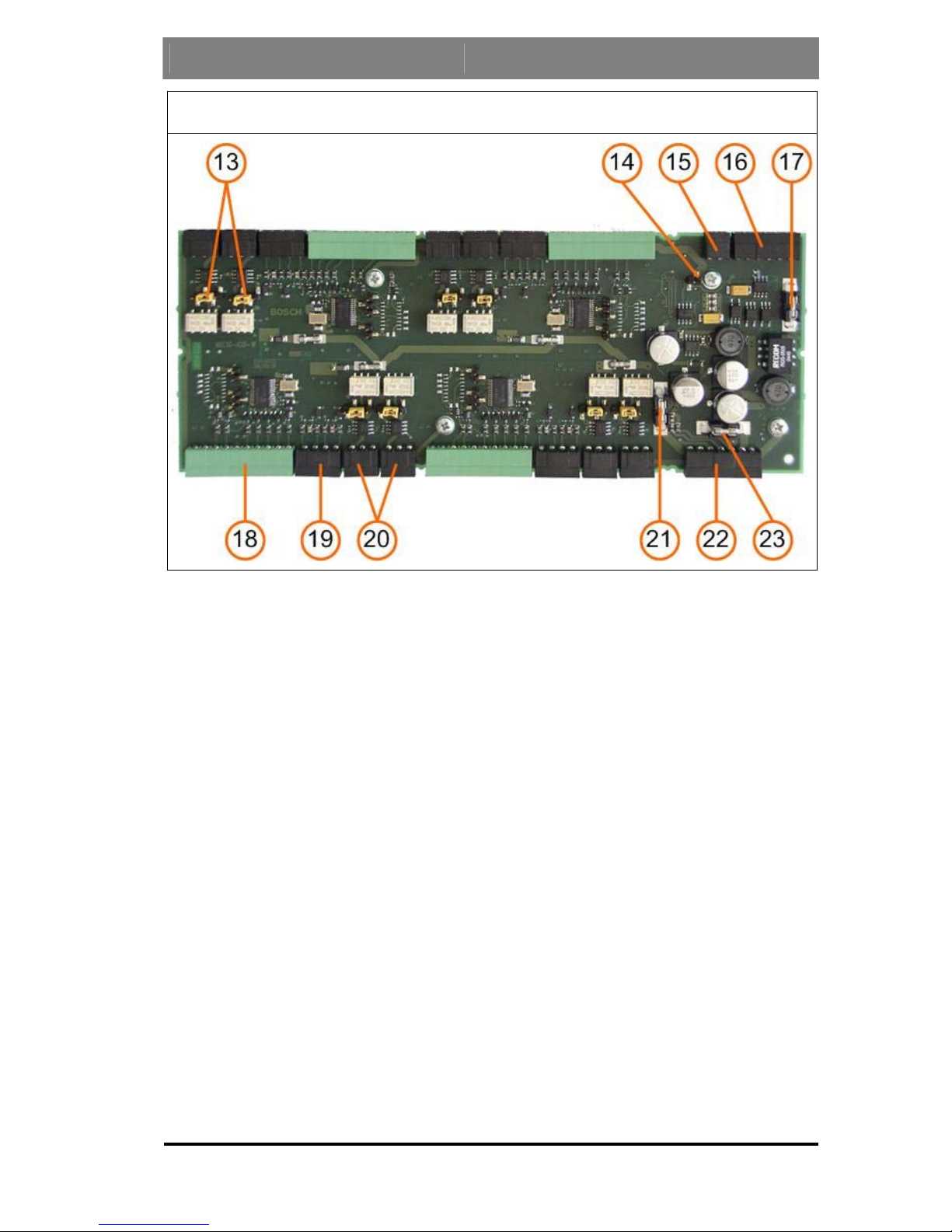
Figure 4: Lower circuit board (bottom side)
13. Jumper: Selector for either potential free relay output or powered by
AMC-4W internal power supply (wet/dry contacts)
14. Jumper: Potential equalization between different mass systems and
protective earth (shield)
15. External tamper contact (Pluggable screw connector)
16. RS485 extension module bus (Pluggable screw connector)
17. Fuse RS485 extension module bus; 6300mA time lag
(i.e. Schurter 7010.ggbg, 125V DC, T, 6300mA)
18. Wiegand interface for card readers (Supply current max. 200mA)
19. Analog input (Pluggable screw connector)
20. Relay Output (Pluggable screw connector, max 1,25A at 12V DC)
21. Fuse: Power supply electronics, 750mA time lag
(i.e. Schurter 7010.ggbo, 125V DC, T, 750mA)
22. Power supply (Pluggable screw connector)
23. Fuse Power supply peripherals, 6300mA time lag
(i.e. Schurter 7010.ggbg, 125V DC, T, 6300mA)

Description of the AMC-4W Access Controller AMC-4W
16 Installation Guide Bosch Security Systems | V.3.1/2006-09
Figure 5: Lower circuit board connections (bottom side)
3.2. Performance Characteristics
- Host address selectable via DIL sliding switch
- Four possible configurable host interfaces:
- RS485 2-wire
- RS485 4-wire
- RS232
- Ethernet 10/100 Mbit/s
- Four peripheral input devices via Wiegand interface
- Eight relay outputs
- potential-free or
- with internal power supply
- Eight analog inputs with internal power supply
- Battery buffered SRAM and real time clock (RTC)
- Pluggable Compact Flash from 64 MB to 1024 MB
- Connector for LC Display
- Transfer rate host interface RS485: 38,4 kBit/s
- Wiegand interface
- Self controlling transfer-receive-switching
Access Controller AMC-4W Description of the AMC-4W
- Power supply for internal electronics: 10V - 35V DC
- Power supply for peripherals: 12V DC
- The AMC-4W is to be used with power supply Deutronic E-TOP60-12 or
Altronix AL600ULX
- Optional uninterruptible power supply Deutronic D-TOP-BAT-LCB 12-12
or Altronix AL600ULX
- The AMC-4W is to be used with mounted enclosure only
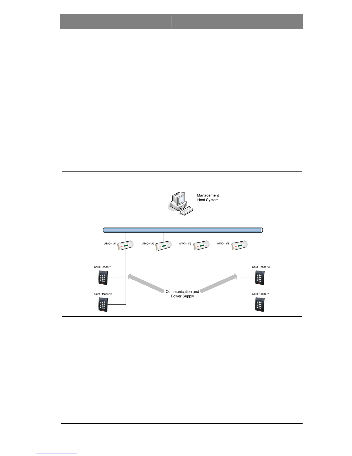
3.3. System Overview
The Access Controller AMC-4W is connected between the management host
system and different peripheral devices.
Figure 6: System overview
By default a management host system is connected via Ethernet. A
management host connection via RS485 or RS232 is also possible.
In RS485 mode up to eight access controllers AMC-4W can be combined on
one party line. Via Wiegand interfaces up to four peripheral devices can be
connected to each AMC-4W.
Bosch Security Systems | V.3.1/2006-09 Installation Guide 17
 Loading...