

Page 1
AMC UL2 Housing | en 1
Included Parts
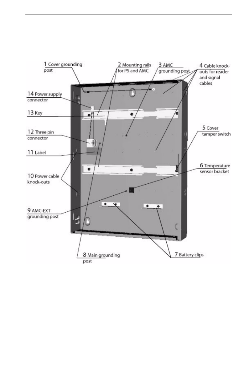
The metal housing inlcudes the following components:
Figure 1 Parts of the housing
The accessories kit includes the following cables. Install these
cables as described in Section Connection of the Devices,
page 4.
Bosch Security Systems Assembly Instruction F.01U.029.481 | V.2 | 2006.08
Page 2
2 en | AMC UL2 Housing
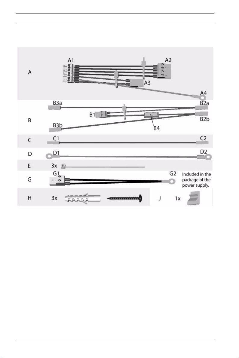
Figure 2 Accessories kit content
Content of the accessories kit:
A = Pre-assembled cable to connect the AMC to the power sup-
ply
B = Pre-assembled cable to connect the batteries to the UPS
(uninterruptable power supply) which is included in the power
supply
C = Cable using 24 V mode
D = Grounding cable for the cover
E = Cable ties to secure the pre-assembled cable
G = Pre-assembled cable with temperature sensor
H = Three screw anchors S8 and wood screws M6 x 50
J = Bracket for cable fixing
F.01U.029.481 | V.2 | 2006.08 Assembly Instruction Bosch Security Systems
Page 3
AMC UL2 Housing | en 3
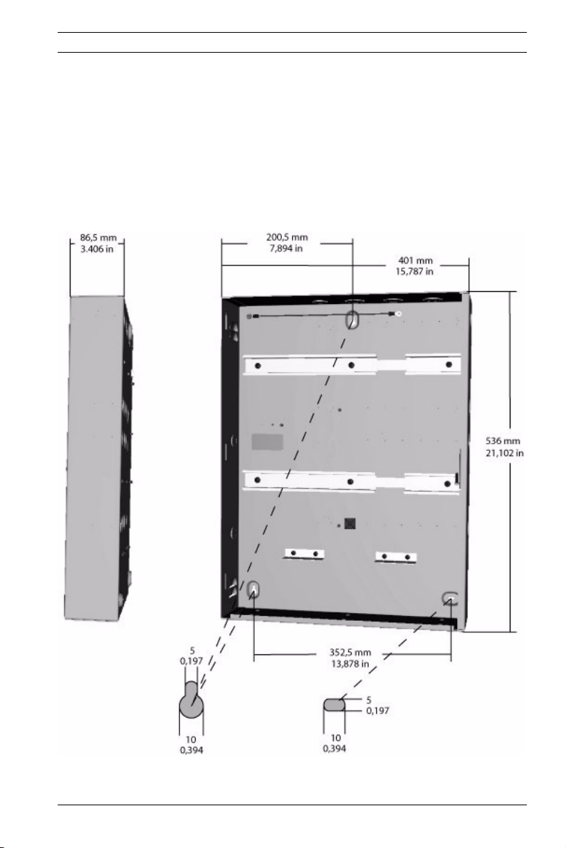
Mounting the Housing
Open the housing cover lock with the provided key and remove
the hood from the wall mounted frame.
Mount the metal housing at the desired position with the screw
anchors provided with the enclosure.
Use the screws (position H of the accessories kit) at the points
to mount the housing against the wall.
Figure 3 Demensions of the housing
Bosch Security Systems Assembly Instruction F.01U.029.481 | V.2 | 2006.08
Page 4
4 en | AMC UL2 Housing
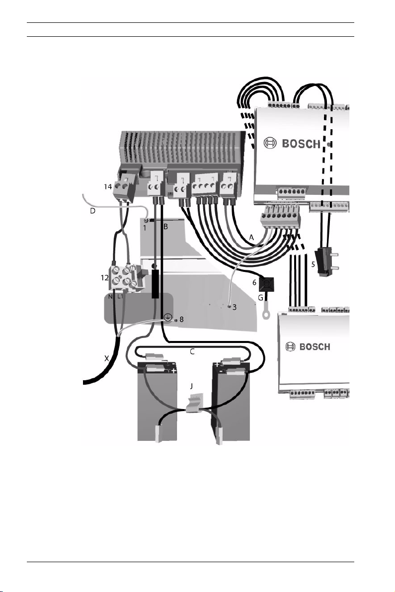
Connection of the Devices
Figure 4 Connection of the devices
F.01U.029.481 | V.2 | 2006.08 Assembly Instruction Bosch Security Systems
Page 5

AMC UL2 Housing | en 5
NOTE!
The following steps describe connecting the batteries in 24 V
i
mode. For information on 12 V mode connections, refer to
Section 12 V Mode Variations, page 8.
1. Mount the AMC on the rail (item 2 in Figure 1) and left
aside the power supply. The second mounting rail is
planned for the extension board.
2. Put the batteries on the bottom of the housing and secure
them beneath the battery clips (item 7 in Figure 1).
3. Stick the bracket J (Figure 2) on the back of the housing in
such a way that later on not used connectors of the cable
B can fixed with it.
4. Cable set A:
a. Connect the 7-pin plug A1 to the AMC’s power supply
connector (labeled: POWER).
b. Attach connectors A3 to the PS-interface DC and A2
to the interface labeled OK.
c. Connect the grounding cable A4 beneath the ground-
ing point 3.
5. Cable set B:
a. Connect the plug connector B1 the second position
from the left on the power supply - labeled with BAT.
b. Attach connector B2b (red) to the
battery.
c. With cable C connect the
--pin of the first battery to
+-pin of the first
the
+-pin of the second battery.
d. Attach connector B2a (black) to the
ond battery.
e. Connectors B3a and B3b are not used.
6. Cable set G:
a. Attach connector G1 on the PS-interface labbeled
RTH.
Bosch Security Systems Assembly Instruction F.01U.029.481 | V.2 | 2006.08
--pin of the sec-
Page 6
6 en | AMC UL2 Housing
b. Route the cable across the temperature sensor
bracket 6 so that the temperature sensor G2 hangs
approximitely 5 cm (2 in.) above the batteries.
7. Pre-assembled cable set 12:
a. Connect the 2-pin plug 14 on the interface AC of the
power supply.
8. Pre-assembled cable 5:
a. Connect the loose ends of the cover tamper switch to
the 2-pin screw connector on the top of the AMC.
Position the cable in the space between the housing
and the mounting rail.
DANGER!
Remove the fuse from the three-pin connector 12 before pro-
!
ceeding with the power supply connection.
Do not install the fuse before completing the installation procedure.
9. Connect the main AC supply X:
a. Connect the brown (phase) wire to terminal L1.
b. Connect the blue (neutral) wire to terminal N.
c. Connect the grounding cable to the housing at posi-
tion 11.
CAUTION!
Shorten the external supply wires so that the ground (yellow/
!
F.01U.029.481 | V.2 | 2006.08 Assembly Instruction Bosch Security Systems
green) wire is at least 20 mm (0.8 in.) longer than the live (blue
and brown) wires. This ensures that the ground wire cannot be
accidentally disconnected before life wires.
10. Connection of the extension board:
a. The extension board will be connected via the RS-485
interface of the AMC (on the left side of the tamper
contact). On the extension board itself use the same
interface.
Page 7

AMC UL2 Housing | en 7
b. Additional to the data lines (pin 3 and 6) connect the
power supply (pin 1 and 2), too.
NOTE!
Connect the readers and other peripheral devices as described
i
in the AMC Installation Manual (P/N: F01U.028.713). Route the
device cables through the knock-outs in the top an right side
wall of the housing, or through the rear of the housing.
11. Cable D:
If this cable is not pre-installed on grounding point 1, use
the cable D from the accessories kit.
a. Connect D1 to grounding post 1.
b. Connect D2 to the grounding post on the cover.
12. Install the fuse.
13. Close the cover.
Bosch Security Systems Assembly Instruction F.01U.029.481 | V.2 | 2006.08
Page 8

8 en | AMC UL2 Housing
12 V Mode Variations
Figure 5.1 + 2 12 V mode with one and two batteries
The 12 V mode can be configured using one or two batteries.
For a one-battery installation, refer to Figure 5.1, and perform
the following procedure:
1. Connect B1 to the power supply position labbeled BAT.
2. Connect B2a (black) to the battery’s - terminal, and B2b
(red) to the battery’s
3. Connectors B3a and B3b remain unused - fix them with the
bracket J.
For the two-battery installation, refer to Figure 5.2, and perform
the following procedure:
1. Connect B1 to the power supply position labbeled BAT.
2. Connect B2a (black) to the battery’s
(red) to the battery’s + terminal.
F.01U.029.481 | V.2 | 2006.08 Assembly Instruction Bosch Security Systems
+ terminal.
- terminal, and B2b
Page 9

AMC UL2 Housing | en 9
3. Connect B3a (black) to the second battery’s - terminal,
i
and B3b (red) to the second battery’s
NOTE!
To switch the power supply between 12 V or 24 V modes, disconnect the input voltage and set the switch as shown in the
figure below.
+ terminal.
Bosch Security Systems Assembly Instruction F.01U.029.481 | V.2 | 2006.08
Page 10

10 en | AMC UL2 Housing
F.01U.029.481 | V.2 | 2006.08 Assembly Instruction Bosch Security Systems
Page 11

AMC UL2 Housing | en 11
Bosch Security Systems Assembly Instruction F.01U.029.481 | V.2 | 2006.08
Page 12

12 en | AMC UL2 Housing
F.01U.029.481 | V.2 | 2006.08 Assembly Instruction Bosch Security Systems
 Loading...