


Radio / CD
Atlanta
RD 105
Einbauanleitung
Fitting instructions
Instructions de montage
Istruzioni di montaggio
Inbouwinstrukties
Monteringsanvisning
Instrucciones de montaje
Instruções de montagem
ATLANTA
3 D94 653 070 (2.95)
Sicherheitshinweise
Einbauund Anschlußvorschriften
Für die Dauer der Montage und des Anschlusses ist der Minuspol der Batterie abzuklemmen.
Hierbei sind die Sicherheitshinweise des KfzHerstellers (Airbag, Alarmanlagen, Bordcomputer, Wegfahrsperren) zu beachten.
Beim Bohren von Löchern darauf achten, daß keine Fahrzeugteile (Batterie, Kabel, Sicherungskasten) beschädigt werden.
Der Querschnitt des Pluskabels darf 2,5 mm2 nicht unterschreiten. Das Gerät ist mit einer Sicherung, 10 A flink, abgesichert.
Das Seitenteil des Autoradiogehäuses wird im Betrieb sehr heiß.
Achtung: Es ist darauf zu achten, daß keine Kabel am Gehäuse anliegen.
D
Anschluß mit fahrzeugseitigen Systemsteckern
Fahrzeugseitige Plus-/ Minus-Systemstecker nicht verwenden.
Für den Plus- / Minusanschluß das Anschlußkabel 7 607 884 093 verwenden, Fig. 4, 5.
In einigen Mercedes-Fahrzeugen liegt ein 10poliger Stecker im Einbauschacht. Dieser Stecker darf nicht am Autoradio angeschlossen werden, da sonst der Schaltplus für Antenne/Verstärker gegen Masse kurzgeschlossen wird und eine Leiterbahn im Radio aufbrennt.
Hinweis:
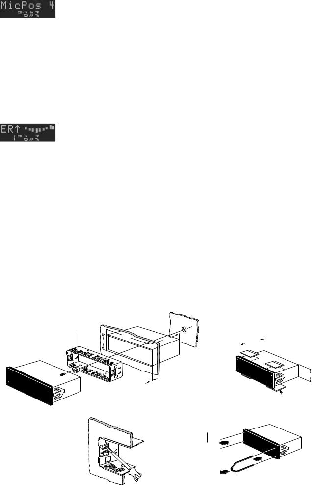
Die zum Lieferumfang dieses Autoradios gehörende Halterung ermöglicht den Einbau in Fahrzeugen mit DIN-Autoradioausschnitt von 182 x 53 mm, 165 mm Einbauraum und einer Instrumententafeldicke im Bereich der Befestigungslaschen von 1 - 20 mm, siehe Fig. 1.
Für Fahrzeuge mit abweichender Einbausituation liefert Blaupunkt für die gängigsten Fahrzeuge fahrzeugspezifische Einbausätze für 50/
52 mm Geräte.
Prüfen Sie daher, ob die Einbausituation im Fahrzeug vorliegt, und verwenden Sie zum Einbau gegebenenfalls einen fahrzeugspezifischen Einbausatz, z. B. Audi A4/A6/A8: 7 608 0214 73.
Bei Verwendung von Einbausätzen für 52 mm Geräte sind 4 Distanzplatten, Best.-Nr. 8 601 055 056 zu verwenden, Fig. 1a.
Autoradioeinbauvorbereitung
Das Autoradio wird in den vom Fahrzeughersteller vorgesehenen
Autoradioausschnitt eingebaut.
Autoradioausschnitt freilegen (Ablagefach oder Blindblende ausclipsen) oder Autoradioausschnitt auf 182 x 53 mm ausarbeiten.
Hinter den Autoradioausschnitt fassen und prüfen, welche Befestigungslaschen der Halterung umgebogen werden können.
Hinweis: Möglichst alle Befestigunglaschen umbiegen.
Halterung in den Ausschnitt einsetzen und die Befestigungslaschen mit einem Schraubendreher umbiegen, siehe Fig. 1, 2.
Anschluß
Anschlußhinweise ....................................................................... |
Fig. 4 |
Plus-/Minus-Anschluß ................................................................. |
Fig. 5 |
Equalizerund Amplifieranschluß ................................................ |
Fig. 6 |
Dem Amplifier beiliegendes Anschlußkabel verwenden oder Anschlußblock 7 607 874 003 verwenden.
Lautsprecheranschluß:
4 Lautsprecher (4 Ω/25 W) ......................................................... |
Fig. 7 |
Anschluß mit fahrzeugseitigem QuickOut
Bei Fahrzeugen, die fahrzeugseitig mit QuickOut ausgerüstet sind (z.Z.
Opel), muß die fahrzeugseitige QuickOut ausgebaut und Adapterkabel verwendet werden.
Autoradioeinbau
Autoradio von vorn in die Halterung einsetzen und einschieben, bis die seitlichen Rastfedern rechts und links arretieren (deutliches Knacken hörbar).
Autoradioausbau
Bügel links und rechts in die vorhandenen Löcher der Blende stecken und so weit eindrücken, bis deutliches Knacken zu hören ist (seitliche Federn entriegelt).
Gerät an den beiden Bügeln herausziehen, siehe Fig. 3.
Hinweis: Eingerastete Bügel können nur nach Herausziehen des Gerätes entfernt werden.
Auszug aus Bedienungsanleitung!
DSA
Digital Signal Adaptation – digitale Signalanpassung
Nach erfolgtem Einbau können Sie mit DSA Equalizer-Funktionen aufrufen und einstellen und die dynamische Fahrgeräuschmaskierung
DNC durchführen.
Übersicht Equalizerfunktionen
Die HiFi-Wiedergabe im Fahrzeug wird z.B. beeinflußt durch die Fahrzeuginnenausstattung (Polster, Scheiben), Anordnung der Lautsprecher usw.
Mit dem integrierten Equalizer sind neun Frequenzbänder pro Kanal einstellbar:
60 Hz, 125 Hz, 250 Hz, 500 Hz, 1 kHz, 2 kHz, 4 kHz, 8 kHz, 16 kHz.
Auf je fünf Speicherplätzen (Tasten 1 bis 5) können verschiedene
Einstellungen gespeichert und abgerufen werden.
Mit der Taste 6 wird der jeweilige Equalizer ausgeschaltet.
Für eine optimale Klangaussteuerung stehen folgende Möglichkeiten zur Verfügung:
Selbsteinmessender Equalizer
(HiFi-Einmessung)
Das Gerät ist mit einem selbsteinmessenden, adaptiven 9-Band-Equa- lizer für vier Kanäle ausgestattet.
Pro Speicherplatz können vier Kanäle elektronisch eingemessen werden (vorn links, vorn rechts, hinten links, hinten rechts).
Manueller Equalizer
Pro Speicherplatz können für vorn und hinten separate Equalizer-
Einstellungen manuell durchgeführt werden.
Preset-Equalizer
(werkseitig fest eingestellt)
Mit den Tasten 1 bis 5 oder mit  /
/ / << >> können nicht veränderbare
Equalizer-Einstellungen abgerufen werden:
1 ROCK, 2 DISCO, 3 JAZZ, 4 CLASSIC, 5 VOCAL, 6 P - EQ OFF
HiFi-Einmessung
Sie können für fünf verschiedene Situationen elektronische Einmessungen vornehmen und speichern.
Diese Einmessungen werden über die Tasten 1 bis 5 gespeichert und abgerufen.
Sie können z.B. folgende Situationen wählen:
1für Fahrer allein
2für Fahrer und Beifahrer
3Beifahrer
4Insassen vorn und hinten
5Insassen nur hinten.
Mit Taste 6 schalten Sie den Equalizer aus. (“EQ OFF” im Display.)
Zur Einmessung befestigen Sie das Mikrofonkabel (Mikrofon-Öffnung nach unten) mit Klebeband am Fahrzeughimmel.
Die Position des Mikrofons für die Situation 1 (Fahrer allein) ist direkt in
Höhe des Fahrerkopfes. Für Situation 2 ist das Mikrofon zwischen Fahrer und Beifahrer, für Situation 3 in Höhe des Beifahrerkopfes usw.
HiFi-Einmessung starten
Für die Einmessung muß eine wirklich ruhige Umgebung vorhanden sein. Fremdgeräusche verfälschen die Messung.
Es sollten keine Insassen im Fahrzeug sein, Gegenstände dürfen die Abstrahlung der Lautsprecher nicht beeinträchtigen.
Die Anlage muß eingeschaltet sein.
•Plazieren Sie das Mikrofon für die einzustellende Situation.
Es kommt zu Fehleinmessungen, wenn das Mikrofon falsch plaziert ist.
Bedingt durch das Fahrzeug und den Einbauort der Lautsprecher kann die Einmessung linear oder baßbetont erfolgen.
Probieren Sie selbst, welche Einstellung Ihnen am besten zusagt. Die Vorwahl führen Sie mit DNC durch. Dabei bedeutet
DNC-OFF |
- |
linearer Frequenzgang |
DNC-LOW |
- |
leichte Baßbetonung |
DNC-MID |
- |
mittlere Baßbetonung |
DNC-HIGH |
- |
stärkere Baßbetonung |
•Drücken Sie DSA zweimal kurz.
Im Display erscheint die aktuelle DNC-Einstellung.
•Wählen Sie mit << >> die Einstellung, mit der Sie die HiFi-
Einmessung durchführen wollen.
•Drücken Sie DSA zweimal kurz.
•Drücken Sie -dB so oft, bis “EL” erscheint.
•Drücken Sie die entsprechende Taste (1 bis 5) ca. 2 Sek. lang
(BEEP).
Im Display erscheint “MicPos 8”, der count down läuft. Sie haben jetzt
8 Sek. Zeit, das Fahrzeug zu verlassen. Anschließend beginnt die vollautomatische Einmessung.
Sorgen Sie bei diesem Vorgang für größtmögliche Ruhe.
Sobald der Einmeßvorgang beendet ist, zeigt das Display “EQ-READY” und schaltet in den zuletzt eingestellten Betriebszustand.
HiFi-Einmessung überprüfen/verändern
Bei Bedarf können Sie die automatische Einmessung eines Kanals überprüfen und korrigieren:
•drücken Sie DSA kurz,
•drücken Sie -dB so oft, bis “EL” erscheint.
Die vier anwählbaren Kanäle erscheinen im Display mit folgenden
Zeichen:
EL  - vorn links
ER  - vorn rechts
EL  - hinten links ER
  - hinten rechts
•wählen Sie mit  /
/ den Kanal.
•Das evtl. zu korrigierende Frequenzband wählen Sie mit << >>.
Die eingestellte Frequenz wird durch einen blinkenden Balken angezeigt.
•Mit  /
/ können Sie die Aussteuerung des Frequenzbandes verändern.
Nach erfolgten Änderungen drücken Sie << >>, bis kein Frequenzband mehr blinkt.
Ändern Sie bei Bedarf weitere elektronisch eingemessene Kanäle wie zuvor beschrieben.
Die letzte Einstellung ist automatisch gespeichert.
Hinweis:
Bei der Einmessung sollten alle vier Lautsprecheranschlüsse belegt sein.
Wird bei der HiFi-Einmessung ein Lautsprecher nicht erkannt, weil dieser defekt ist, nicht angeschlossen oder verdeckt ist, erfolgt für das zugehörige Lautsprecherpaar eine lineare Equalizeraussteuerung.
Die Balance-/Fadereinstellung ist dann entsprechend eingeschränkt möglich.
HiFi-Einmessung abrufen
Soll die Wiedergabe mit der elektronischen HiFi-Einmessung erfolgen,
•DSA kurz drücken.
•Drücken Sie -dB so oft, bis “EL” erscheint.
•Wählen Sie mit den Tasten 1 bis 5 die Equalizer-Einstellung.
Manuelle Equalizer-Einstellung abrufen
Soll die Wiedergabe mit der manuellen Equalizer-Einstellung erfolgen,
•DSA kurz drücken und
•-dB so oft drücken, bis “EQ” im Display erscheint.
•Wählen Sie mit den Tasten 1 bis 5 (kurz drücken) Ihre manuelle Equalizer-Einstellung.
DNC
Dynamic Noise Covering – Fahrgeräuschmaskierung
Mit DNC wird eine bei stehendem Fahrzeug als angenehm empfundene Lautstärke während der Fahrt angehoben.
Die Anhebung erfolgt nach Frequenzbereichen unterschiedlich stark, abhängig von der Geräuschentwicklung im Fahrzeug.
So bleiben Lautstärke und Klangbild auch bei wechselnder Geräuschentwicklung angenehm verständlich. Kurzzeitige Geräusche wie sie z.B. beim Überqueren von Schienen entstehen, werden nicht berücksichtigt.
Einmessen von DNC
Für den fahrzeuggerechten Betrieb ist eine Einmessung über das Meßmikrofon erforderlich. Das Mikrofon wird mit dem beiliegenden selbstklebenden Klettband dauerhaft in Konsolennähe montiert, jedoch nicht direkt an dröhnenden Stellen oder an Lüftung/Heizung.
Die Öffnung des Mikrofons muß in Richtung der Fahrgastzelle zeigen.
Die Einmessung sollte an einem ruhigen Platz mit ausgeschaltetem Motor erfolgen.
•Drücken Sie DSA so oft, bis im Display “DNC-MID”, “-HIGH” oder
“-LOW” oder “DNC-OFF” erscheint.
•Drücken Sie eine beliebige Stationstaste (1 - 6) ca. 2 Sek., bis im Display “MicPos 8” erscheint.
Die DNC-Einmessung ist gestartet und läuft nun automatisch ab.
Den Vorgang können Sie abbrechen, wenn Sie eine Stationstaste (1 - 6) drücken.
Das Display zeigt “DNC-ADJ”, jetzt erfolgt die eigentliche Einmessung.
Sobald das Display “DNC-OK” zeigt, ist der Einmeßvorgang abgeschlossen. Das Display zeigt für ca. 8 Sek. “DNC-MID”.
Illustrationen / Illustrations / Ilustraciones / Illustrazioni / Illustrationer / Afbeeldingen / Ilustraçoes
8 601 310 742
165
150 mm
50 mm
1-20
Fig. 1a
8 601 055 056
Fig. 1
Fig. 1a
8 601 910 002

 1 2
1 2
1
Fig. 2
2
Fig. 3
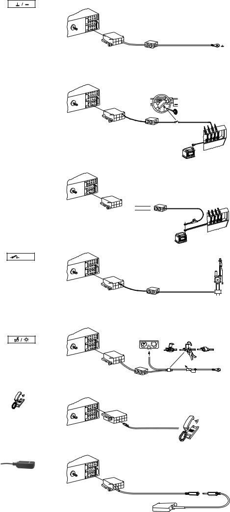
Anschlußhinweise, Fig. 4
Masseanschluß (Ground)
Massekabel nicht am Minuspol der Batterie anklemmen. Massekabel zu einem geeigneten Massepunkt verlegen (Karosserieschraube, Karosserieblech) und entsprechend Massepunkt kürzen.
Massekabel abisolieren und Krallenkabelschuh anschlagen (ggf. nachlöten). Kontaktfläche des Massepunktes metallisch blank kratzen und mit Graphitfett einfetten (wichtig für gute Masseverbindung).
Massekabel anschrauben.
Pluskabelanschluß (ACC + 12 V) |
+12V |
(Ignition)
Wird das Pluskabel am Sicherungshalter Kl.15 (Plus über Zündschloß geschaltet) hinter der Sicherung angeschlossen, so ist das Einund Ausschalten des Autoradios über Zündung möglich.
Außerdem schaltet das Gerät zum Schutz der Batterie automatisch
nach einer Stunde aus.
Die Stunden-Logik wird nicht aktiviert wenn Dauerplus (Kl.30) angeschlossen wird.
Dauerplusanschluß (Battery + 12 V) |
per. +12V |
Fahrzeugseitiges Pluskabel nicht anschließen.
Pluskabel (rot) mit starkem Querschnitt (2,5 mm2) zur Batterie verlegen (Kabel nicht unmittelbar an Kabelbäumen verlegen). Sicherungshalter zur Absicherung des Pluskabels anschließen und am Pluspol der Batterie anklemmen (ggf. Loch in Spritzwand bohren und entsprechend Kabeldurchführung verwenden).
Steuerkabel (Power Antenna +) |
+12V |
Das Steuerkabel ist der geschaltete Plusausgang für externe
Komponenten z.B.: Verstärker Equalizer oder Motorantenne.
Das Steuerkabel nicht an Klemme 15 (Plus geschaltet) oder Klemme 30 (Dauerplus) anschließen.
Bei Anschluß einer vollautomatischen Motorantenne Steuerkabel von der Motorantenne mit einer Kabelklemme am Steuerkabel anklemmen.
Beleuchtungsanschluß (Illumination)
Beleuchtungsanschluß für Fahrzeuge mit regelbarer Instrumentenbeleuchtung (plusgeregelt).
Telefon Mute (low)
Bei Anschluß eines Telefons wird das Autoradio während des
Telefonierens stummgeschaltet.
Meßmikrofon
Das Meßmikrofon dient zur Aufnahme von Störgeräuschen, zur DNC-Steuerung, sowie zur HIFIund DNC-Einmessung.
Changer dürfen hier nicht angeschlossen werden.
5A
Störfreier Massepunkt
5A
Kl. 15
.30 |
Kl |
12 |
V |
5A
 per +12V
15A
12V
5A

 .30 Kl
+12V 
5A |
1 |
2 |
|
||
|
|
3
+
5A
PIN 4
8 604 492 321
5A

 Kl. 15
.30 Kl
 15A
15A
12V
Symbolerklärung
siehe Fig. 4
5A
7 607 884 093 |
|
|
+12V |
br |
|
+12V |
||
rt |
||
|
||
per.+12V |
ge/gn |
|
|
or |
rt
1 |
2 |
per.+12V |
|
||
|
|
3 |
Fig. 5

 Preamp Out
5A
7 607 863 001
5m
Amplifier |
Equalizer |
RF RR
LF LR
Fig. 6
 LF RF LR RR
RF RR
LF LR
Fig. 7
GB
Notes on Safety
Instructions for installation and connection
Disconnect the battery ground wire during installation and connection.
When drilling a hole, be sure not to damage any vehicle part (battery, cable, fuse, etc.).
The positive cable must have a cross-section of at least 2,5 mm2. The unit is protected by a quick-acting fuse of 10 A. Do not use the positive cable installed ex factory.
The side panel of the car radio heats up considerably during operation.
Attention: Pay attention that the cables do not contact with the housing.
Connection with in-vehicle system plugs
Do not use the positive/negative system connectors provided in the vehicle!
For connecting all positive and negative wiring, use connection cable 7 607 884 093, fig. 4, 5.
Some Mercedes vehicles are equipped with a 10-pin connector located in the installation compartment.
This connector must not be hooked up to car radio, since otherwise the positive supply line feeding the antenna or amplifier would be shortcircuited to ground! As a result, one of the conductive tracks in the radio would start burning.
Note:
By means of the support included in the delivery you can mount the set in cars with a DIN car radio cut-outout of 182 x 53 mm, an installation depth of 165 mm and an instrument panel thickness around the fixing clips of 1 - 20 mm, see fig. 1.
For cars with other cut-out dimensions Blaupunkt delivers car-specific installation kits for common car types for 50/52 mm sets.
Please check the dimensions and, if necessary, use a car-specific installation kit, e. g. VW Golf II / Jetta II/: 7 608 3824 73.
When using installation sets for units of 52 mm four distance plates, order number 8 601 055 056, must be used, fig. 1a.
Preparation of car radio installation
Install the car radio into the DIN cut-out provided in your car’s dashboard ex factory.
Prepare the car radio DIN cut-out (unlock shelf or dummy cover) or cut out the car radio compartment to 182 x 53 mm.
Grasp behind the car radio cut-out and check how many of the fixing strips of the car radio support can be bent.
Note: Try to bend as many fixing strips as possible.
Insert the support into the cut-out and bend the appropriate fixing strips with a screwdriver, see fig. 1, 2.
Connection
Notes on connection ..................................................................... |
fig. 4 |
Plus/minus-Connection ................................................................. |
fig. 5 |
Connection of equalizer and amplifier .......................................... |
fig. 6 |
Use the adapter cable enclosed to the amplifier or the adapter cable 7 607 874 003.
Loudspeaker connection: |
|
4 speakers (4 Ω/25 W) .................................................................. |
fig. 7 |
Connection with QuickOut installed ex factory
If your car is fitted with a QuickOut ex factory (at present Opel), the QuickOut ex factory has to be removed.
Car radio installation
Insert the car radio from the front into the support and push in until the stop springs on the sides engage right and left (distinct click to be heard).
3 D94 653 070 (2/95)
Removal of the car radio
Insert the brackets right and left into the provided trimplate holes and push in until you hear a distinct click (lateral springs are unlocked).
Using both brackets (see fig. 3), pull the unit out.
Note
Locked brackets can only be removed after taking out the unit.
Extracts from operating instructions!
DSA
Digital Signal Adaptation
With DSA, you can recall and tune in equalizer functions and activate the dynamic driving noise covering function.
Overview of equalizer functions
The HiFi reproduction in a car is affected, for example, by the interior fittings (upholstery, windows), loudspeaker positioning, etc.
With the integrated equalizer, you can tune in nine frequency bands per channel: 60 Hz, 125 Hz, 250 Hz, 500 Hz, 1 kHz, 2 kHz, 4 kHz, 8 kHz, 16 kHz.
You can store and recall different settings in five memory banks each (preset buttons 1 to 5):
With preset button 6, the corresponding equalizer is deactivated. For optimal acoustic control, the following alternatives are available:
Self-calibrating equalizer
(HiFi calibration)
The set is equipped with a self-calibrating, adaptive 9-band equalizer for four channels.
This function allows you to adjust precise sound settings for each individual speaker (front left, front right, rear left, rear right) by electronic calibration and to store them on the preset buttons.
Manual equalizer
It is also possible to manually adjust different equalizer curves for the front and rear speakers and to store them on the preset buttons.
Preset equalizer
(Default allocation of equalizer)
Preset equalizer settings can be recalled with buttons 1 to 6, or with
 /
/ / << >>.
1 ROCK, 2 DISCO, 3 JAZZ, 4 CLASSIC, 5 VOCAL, 6 P - EQ OFF
HiFi calibration
You can perform and store electronic calibration for five different situations. These calibrations are stored and recalled with the buttons 1 to 5. You can select the following situations, for example:
1For the driver only
2For driver and front passenger
3Front passenger
4Passengers front and rear
5Rear passengers only
You deactivate the equalizer with button 6 (“EQ OFF” in the display.)
To calibrate, you have to fix the microphone lead (microphone opening pointing down) to the roof lining with adhesive tape.
The position of the microphone for situation 1 (driver alone) is directly on a level with the driver’s head. For situation 2, the microphone is between the driver and the front passenger, for situation 3 on a level with the front passenger’s head, etc.
Starting the HiFi calibration
The situation has to be really quiet for calibration, extraneous noises give a false reading.
There should be no-one in the car, objects must not impair the reflection of the loudspeakers. The system must be switched on.
• Position the microphone for the situation to be programmed. Incorrect calibrations result when the microphone is wrongly positioned.
Depending on the vehicle and on the installtion position of the speakers, calibration may be linear or with a bass boost. Try out which setting you like more.
You can preselect with DNC. The following stand for:
DNC-OFF |
- |
linear frequency response |
DNC-LOW |
- |
slight bass boost |
DNC-MID |
- |
medium bass boost |
DNC-HIGH |
- |
stronger bass boost. |
•Press DSA twice briefly.
The current DNC setting appears in the display.
•Use << >> to select the setting you wish to use for the HiFi calibration.
•Press DSA twice briefly.
•Press -dB until “EL” appears.
•Press the corresponding button (1 to 5) for approx. 2 seconds (BEEP).
“MicPos 8” appears in the display, the countdown is on. You now have 8 seconds to leave the car. Fully automatic calibration then commences.
Ensure that everything is as quiet as possible during this process. Once the calibration process is complete, the display shows “EQREADY” and switches to the last set parameter.
Checking/modifying HiFi calibration
If necessary, you can check and correct the sound settings for each speaker channel:
•Press DSA briefly,
•press -dB until “EL” appears.
The four selectable channels appear in the display with the following characters:
EL  - front left
ER  - front right EL
  - rear left
ER  - rear right
•Select the channel with  /
/ .
.
•Select any frequency band you may wish to correct with << >>.
The set frequency is indicated by a flashing bar.
•You can alter the adjustment of the frequency band with  /
/ .
.
When modifications have been completed, press << >> until no more frequency bands are flashing. If necessary, alter further electronically calibrated channels as described above. The last setting is stored automatically.
Please note:
All of the four loudspeakers should be connected for the calibration.
If a loudspeaker is not recognized because it is defective, not hooked up or masked, linear equalizer adjustment is made for the corresponding pair of loudspeakers. Accordingly, the balance/fader setting is only partly possible.
Recalling the HiFi calibration
If you wish to use electronic HiFi calibration in reproduction:
•Press DSA briefly,
•Press -db until “EL” appears.
•Select the equalizer setting with preset buttons 1 to 5.
Recalling the manual equalizer settings
If you want reproduction with the manual equalizer settings,
•press DSA briefly and
•press -dB until “EQ” appears in the display.
•Select any of your manual equalizer settings with buttons 1 to 5
(press briefly).
DNC
Dynamic Noise Covering
With DNC, a volume considered to be pleasant when the vehicle is stationary is boosted during driving.
Depending upon the noise development in the car, the frequency ranges are boosted with different intensity.
Even during changing noise development, the volume and the sound pattern remain pleasantly distinguishable. Short-term noises such as, for example, when crossing railway tracks, are not covered.
DNC calibration
For operation in your particular car, you have to measure the interior acoustics using the test microphone. With the adhesive tape supplied, the microphone is fixed permanently in the vicinity of the console, but not directly in the most droning positions or close to the ventilation/heating.
The microphone opening must be directed towards the passanger compartment. The measurement should be performed in a quiet place with the motor off.
•Press DSA until “DNC-MID”, “DNC-HIGH”, “DNC-LOW” or “DNCOFF” appears.
•Press any preset button (1-6) for approx. 2 seconds until “MicPos
8” appears in the display.
DNC calibration is now in operation and functioning automatically.
You can interrupt the process by pressing a preset button (1-6).
The display indicates “DNC-ADJ”, now actual calibration is taking place. Once “DNC-OK” appears in the display, calibration is complete. The display indicates “DNC-MID” for approx. 8 seconds.
Notes on connection, fig. 5
Ground cable
Do not connect the ground cable to the negative pole of the battery.
Route the ground cable to a suitable ground point (car body screw, car body metal sheet) and shorten it accordingly.
Remove the insulation from the ground cable and attach the forked cable lug (if necessary, solder it).
Scratch off the paint from the contact area of the ground point and lubricate it with graphite grease (important for good ground contact).
Screw on the ground cable.
Positive cable (ACC + 12 V) (ignition) |
+12V |
If the plus cable is connected to pin 15 of the fuse holder (plus connected via ignition lock) downstream of the fuse, the in-car radio can be switched on and off with the ignition key.In addition, the set automatically switches off after one our in order to avoid that the battery goes flat.
The hour logic will not be activated whrn connecting the permanent +12 V line (terminal 30).
Permanent plus connection (Battery +12 V) |
per. +12V |
Do not use the positive cable installed in the car.
Route the positive cable (thick red cable of 2.5 mm2) to the battery (do not route the cable near the cable harnesses). Connect the fuse holder to protect the positive cable and connect it to the positive pole of the battery (if necessary, drill a hole into the fire wall and use cable ducts).
Control cable (Power Antenna +) |
+12V |
The control cable represents the switched positive output for external components, e.g. amplifiers, equalizers, or motor antennas.
Do not connect the control cable to pin 15 (switched +) or pin 30
(permanent +12 V).
When installing an all-automatic motor antenna, connect the motor antenna’s control cable with a cable clamp to the control cable.
Lighting connection (Illumination)
Lighting connection for vehicles with adjustable dashboard lighting (pluscontrolled).
 Loading...