


Installation and Operation Manual
Videohub
April 2017

Welcome
Thank you for purchasing Videohub!
We hope you share our dream for the television industry to become truly creative by allowing anyone to have access to the highest quality video.
Previously, high end television and post production required investing in millions of dollars of hardware, and professional SDI routers have always been way too costly for most people to afford. HD-SDI is even more expensive and, until now, only the largest post production and television facilities could afford HD-SDI routing. Videohub changes all that! Some Videohub models not only give you HD-SDI, but also the latest Ultra HD format, even enabling you to pipe 4K film around your studio just like video.
This instruction manual contains all the information you’ll need to install your Videohub, although it’s always a good idea to ask a technical assistant for help if you are not sure what IP addresses are, or if you don’t know much about computer networks. Videohub is easy to install, however there are a few slightly technical preferences you will need to set after you install it.
Please check our web site at www.blackmagicdesign.com and click the support page to download the latest updates to this manual and Videohub software. Lastly, please register your Videohub when downloading software updates so we can keep you
updated when new software is released. We are constantly working on new features and improvements, so we would love to hear from you!
We hope you get years of use from your Videohub and have lots of fun connecting everyone in your facility together!
Grant Petty
CEO Blackmagic Design
Contents
Videohub Operation Manual
Getting Started |
5 |
Universal Videohub Routers |
25 |
Getting Started with Videohub |
|
5 |
Creating an IP Videohub with |
|
|
Teranex Mini IP Video 12G |
|
5 |
Plugging in Video |
|
5 |
Controlling your Videohub |
|
5 |
Blackmagic Videohub Software |
|
6 |
Smart Videohub CleanSwitch 12x12 |
|
6 |
Connecting Videohub to a Network |
|
6 |
Connect to an Ethernet Network |
|
6 |
Connect to a Videohub Server with USB |
7 |
|
Configuring your Videohub |
|
|
Server Settings |
|
8 |
Configuring Network Settings |
|
|
with a Built In Control Panel |
|
9 |
Smart Videohub Control Panel |
|
10 |
Using the Smart Videohub |
|
|
Control Panel and LCD |
|
10 |
Switching Routes with Smart Videohub |
|
11 |
Videohub Hardware Control Panels |
|
12 |
Introducing Videohub |
|
|
Hardware Control Panels |
|
12 |
GPI and Tally Interface |
|
12 |
Connecting USB to Configure |
|
|
the Control Panel |
|
13 |
Plugging into an Ethernet Network |
|
13 |
Control Panel Button Diagnostics |
|
14 |
Updating the Software in your |
|
|
Videohub Controller |
|
15 |
About Routing Levels |
|
16 |
How to Select Sources and Destinations |
17 |
|
Using Videohub Smart |
|
|
Control as a Cut-Bus Controller |
|
22 |
Universal Videohub 288 |
|
25 |
Universal Videohub 288 |
|
|
Crosspoint Card |
|
26 |
Router Control Cable |
|
27 |
Power Supply |
|
27 |
Building Universal Videohub 288 |
|
27 |
Installing a Universal |
|
|
Videohub 288 Crosspoint Card |
|
28 |
Universal Videohub Status LED’s |
|
29 |
Installing Interface cards |
|
30 |
Installing a Universal |
|
|
Videohub Power Supply |
|
30 |
Installing a second Power |
|
|
Supply while Universal |
|
|
Videohub 288 is running |
|
32 |
Removing a Power Supply |
|
|
while Universal Videohub |
|
|
288 is running |
|
33 |
Installing a Universal |
|
|
Videohub 72 Crosspoint Card |
|
33 |
Universal Videohub 72 |
|
35 |
Universal Videohub 72 |
|
|
Crosspoint Card |
|
36 |
Router Control Cable |
|
36 |
Power Supply |
|
36 |
Building Videohub 72 |
|
37 |
Installing a Universal 72 |
|
|
Crosspoint Card |
|
37 |
Universal Videohub Status LED’s |
|
38 |
Installing Interface cards |
|
39 |
Installing a Universal |
|
|
Videohub 450W Power Card |
|
39 |
SDI Interface Card |
|
40 |
Using Videohub Smart |
|
Universal Videohub Deck |
|
Control as an XY Controller |
23 |
Control Cable |
40 |
Labeling Pushbuttons |
24 |
Universal Videohub Interface Cards |
41 |
3G-SDI Videohub Routers |
42 |
Blackmagic 3G-SDI Videohub Routers |
42 |
Using the Smart Videohub |
|
Control Panel |
43 |
Videohub Router Monitoring |
44 |
Router Monitoring with |
|
Blackmagic MultiView 16 |
44 |
Using the Built in Control |
|
Panel and LCD |
45 |
Blackmagic Videohub Software |
|
47 |
To install your Blackmagic |
|
|
Videohub software |
|
47 |
Windows installation |
|
47 |
Mac OS X installation |
|
47 |
Blackmagic Videohub Setup |
|
47 |
Network Settings |
|
48 |
Customizing Labels |
|
48 |
Naming your Videohub |
|
50 |
Updating your Videohub’s |
|
|
Internal Software |
|
50 |
Blackmagic Videohub Control |
|
50 |
Serial Control Settings |
|
57 |
Touchscreen Computers |
|
57 |
Apple iPad |
|
58 |
Installing the Videohub |
|
|
Software on iPad |
|
61 |
Videohub Hardware Panel Setup |
|
62 |
Network Settings |
|
62 |
Configuring Videohub |
|
|
Master Control |
|
64 |
Configuring Videohub |
|
|
Smart Control |
|
65 |
Configuring GPIs |
|
68 |
Configuring Tally |
|
69 |
Setting up the GPI and |
|
|
Tally Interface |
|
71 |
Configuring the GPI and |
|
|
Tally Interface |
|
71 |
Controlling Blackmagic |
|
|
MultiView 16 with Videohub Software |
|
72 |
Connecting Blackmagic |
|
|
MultiView 16 to Videohub |
|
|
Control Software |
|
72 |
Developer Information |
|
74 |
Blackmagic Videohub |
|
|
Ethernet Protocol v2.3 |
|
74 |
Videohub RS-422 Protocol |
|
79 |
Saving and Loading Labels |
|
|
with Telnet in Mac OS X |
|
82 |
Saving and Loading Labels |
|
|
with Telnet in Windows |
|
83 |
Help |
|
85 |
Replacing a fan in Universal Videohub |
|
85 |
Replacing the fan in |
|
|
Broadcast Videohub |
|
86 |
Regulatory Notices |
|
|
and Safety Information |
|
88 |
Warranty |
|
89 |
Contents

Getting Started
Getting Started with Videohub
Getting started with Videohub is as simple as connecting power and plugging in your video sources and destination equipment. Your Videohub can be controlled using the powerful Videohub Control software, hardware control panel or front panel for some models.
Creating an IP Videohub with Teranex Mini IP Video 12G
If you are looking for information on the creation of an IP Videohub for routing Blackmagic Teranex Mini IP Video 12G units, refer to the Teranex Mini IP Video 12G manual which can be downloaded from www.blackmagicdesign.com/support.
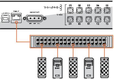
Plugging in Video
To plug in your video sources:
1Connect your video sources to the SDI inputs on the rear panel of your Videohub.
2Connect your destination equipment to the SDI outputs on the rear panel of your Videohub. Your Videohub’s SDI connections will auto detect all supported video formats.
|
|
|
|
Source SDI inputs |
|
|
|
|
|
|
Destinations SDI outputs |
|
||||||||
|
1 |
3 |
5 |
7 |
9 |
11 |
13 |
15 |
17 |
19 |
1 |
3 |
5 |
7 |
9 |
11 |
13 |
15 |
17 |
19 |
REF IN |
RS-422 |
|
|
|
|
|
|
|
|
|
|
|
|
|
|
|
|
|
|
|
CNTRL 2 |
4 |
6 |
8 |
10 |
12 |
14 |
16 |
18 |
20 |
2 |
4 |
6 |
8 |
10 |
12 |
14 |
16 |
18 |
20 |
|
ETHERNET |
USB 2.0 |
|
|
|
|
SD/HD/3G/6G-SDI IN |
|
|
|
|
|
|
|
|
|
SD/HD/3G/6G-SDI OUT |
|
|
|
|
Connect your sources and destination equipment to your Videohub’s SDI inputs and outputs.
Controlling your Videohub
There are two ways to control your Videohub:
1Connect your Videohub to your computer via Ethernet and use the intuitive Videohub Control software to control your Videohub.
Refer to the ‘connecting Videohub to a network’ section in this manual for more information.
2Control your Videohub using a hardware control panel, either built in or external depending on the model.
For example, Smart Videohub models have a built in control panel, LCD and rotary knob for making fast routing changes directly from your Videohub router. For more details, see the ‘switching routers with Smart Videohub’ section in this manual.
Smart Videohub 20 x 20
1 |
4 |
7 |
10 |
13 |
16 |
19 |
SRC |
MENU |
2 |
5 |
8 |
11 |
14 |
17 |
20 |
DEST |
VIDEO |
3 |
6 |
9 |
12 |
15 |
18 |
CLEAR |
TAKE |
Routing changes can be done directly with the Smart Videohub models.
Getting Started |
5 |
Blackmagic Videohub Software
‘Blackmagic Videohub Control‘ is one of the three Blackmagic Videohub software applications. Also included are ‘Blackmagic Videohub Setup‘ and ‘Blackmagic Videohub Hardware Panel Setup‘ that are used for configuring settings and updating internal software.
For Videohub software installation instructions, see the ‘Blackmagic Videohub software‘ section.
Using Blackmagic Videohub Setup, you can customize your source and destination labels so you can easily identify them. Refer to the ‘Blackmagic Videohub setup’ section to learn more about customizing labels.
Smart Videohub CleanSwitch 12x12
When you need to cleanly switch between video sources to monitors or directly to air, you will need timed or genlocked signals. If you cannot guarantee perfectly timed source signals but you still need to clean switch, then you can use Smart Videohub CleanSwitch 12x12 as this model features resynchronization on all inputs so you get perfect clean feeds.
Smart Videohub CleanSwitch 12x12 includes full resynchronization on every input so the router automatically re times all inputs to ensure clean, glitch free switching between router cross points. Sources of the same resolutions and the same frame rate can even be output directly to air for smooth, cuts only production. The SmartVideohub CleanSwitch 12x12 will lock to the reference input or to Input 1 if no reference signal is connected. The video format of the reference signal and all inputs need to be identical for glitch free switching. You can still switch between mixed video formats, however they will not be synced.
Connecting Videohub to a Network
Connect to an Ethernet Network
Many Videohub models have an Ethernet port and can connect directly to your Ethernet network switch or a computer on your local area IP based network.
To connect Videohub to a network:
1Securely connect and power on all of the power supplies included with your Videohub.
2Connect your Videohub router to the network switch or computer Ethernet port with a standard RJ45 Ethernet cable.
Micro Videohub connecting to an Ethernet Network.
Connecting Videohub to a Network |
6 |
If you have a Universal Videohub 288 populated with two Crosspoint Cards, connect Ethernet cables to both for network failover redundancy. Your Universal Videohub 288 will have a single IP address, despite having two Ethernet connections to the network switch.
For Smart Videohub models with a built in control panel, you can use the rotary knob and buttons to configure IP address and network settings, or use Blackmagic Videohub Setup. For models without a front control panel, set your network settings using Blackmagic Videohub Setup. Refer to the Blackmagic Videohub Setup section of this manual for more information. Network settings adjustments using Blackmagic Videohub Setup can only be adjusted when connected to your Videohub via USB.
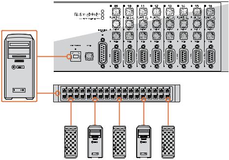
Connect to a Videohub Server with USB
Non ethernet enabled Videohubs can connect to any computer on your local area IP based network via USB. One “server” computer on your network connects to Videohub via the plug and play USB connection, and shares the Videohub with other computers and iPads on your network in a similar way to USB printer sharing. You don’t need a dedicated or powerful computer for this task.
The Videohub Server can be any computer running Mac OS X or Windows. Any number of Mac OS X and Windows clients can connect to the server over the network.
To connect Videohub to the local area IP based network:
1Securely connect and power on all of the power supplies included with your Videohub.
2Connect the Videohub router to the Videohub Server computer with a standard USB 2.0 type A-B male cable.
3Connect the Videohub Server computer to your network switch. We strongly recommend connecting the Videohub Server computer with reliable Ethernet cables in preference to wireless networking. Wireless networking may be affected by interference from appliances and other wireless devices.
Turn the page to proceed with “Configuring your Videohub Server Settings” section.
Studio Videohub connecting to a server via USB.
Connecting Videohub to a Network |
7 |
Configuring your Videohub Server Settings
If you will be using Ethernet to connect to your Videohub, refer to the “Blackmagic Videohub Setup” section in this manual.
Videohubs without Ethernet are connected to a computer via USB and other control panels can see the Videohub by looking for this computer. It effectively becomes a “server”, that all the other control panels on the network can connect to.
A Videohub “server” needs a static IP address and your network administrator will probably want to configure this for you. Please follow the steps below for your respective
operating system.
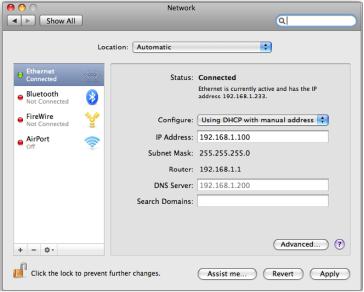
Mac OS X
1Go to System Preferences
2Click on Network
3Check the IP address in the configuration information for your Ethernet or Airport network.
4Set the network configuration to either Using DHCP with manual address or Manually.
Network Preferences in Mac OS X set to “Using DHCP with manual address” to provide a static IP address.
Windows 7
1Open Control Panel
2Click on the Network and Sharing Center.
3Next to your connection, click Local Area Connection for Windows 7.
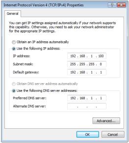
4Click on Properties and Select Internet Protocol Version 4 (TCP/IPv4).
5Click on Properties. Ensure “Use the following IP address” has been selected.
Windows 8
1From the desktop, hover over the right corner to bring up the charms bar.
2Click on Settings, then Control Panel.
Connecting Videohub to a Network |
8 |
3Click on the Network and Sharing Center.
4In the Network and Sharing Center, click on Change Adapter Settings on the left menu pane.
5Right click on your Ethernet connection and select Properties.
6Select Internet Protocol Version 4 (TCP/IPv4).
7Click the Properties button. Ensure “Use the following IP address” has been selected.
Network control panel in Windows set to “Use the following
IP address” to provide a static IP address.
Configuring Network Settings with a Built In Control Panel
You can use Smart Videohub models’ built in control panel and LCD to configure network settings. Your router will be visible to other computers and hardware panels and these devices can then control the unit remotely and make the routing changes. If your router does not have a front panel control, then you should use Blackmagic Videohub Setup to configure your Videohub’s network settings. Refer to the ‘Blackmagic Videohub Setup’ section for more information.
To set the IP address using the front control panel:
1Press the ‘menu’ button to open the ‘settings’ menu.
2Use the rotary knob to scroll down to ‘network’ settings. The ‘take’ button will flash. Press the ‘take’ button to confirm the selection.
3Rotate the knob to select the entry you want to change and press ‘take’ to confirm.
4Use the rotary knob to change a number field. Press the ‘take’ button to confirm the change and move through the fields.
5Make sure you confirm the last change by pressing the ‘take’ button. You will know your settings are confirmed when the field entries are no longer highlighted.
6Press the ‘menu’ button to exit the settings menu and return to your source and destination status.
If required, the subnet and gateway address can be set by the same method.
Connecting Videohub to a Network |
9 |
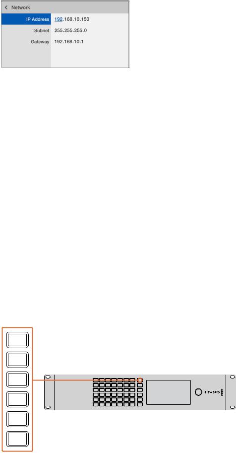
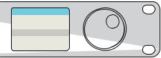
Press MENU to enter the network page and use the
TAKE button and rotary knob to set the IP address.
Smart Videohub Control Panel
Using the Smart Videohub Control Panel and LCD
Smart Videohub routers include Blackmagic Smart Videohub 12x12, 20x20 and 40x40, plus Smart Videohub CleanSwitch 12x12. These models feature a built in control panel and LCD. Routing changes can be made without a computer by pressing the numbered pushbuttons on the front control panel. Remote router control can also be used.
Menu Buttons Explained
MENU
Switches between the routing display and the network configuration page.
VIDEO
Use this button in conjunction with the ‘src’ and ‘dest’ buttons to display either the source or destination video on the LCD.
SRC
Press this button and then a numbered pushbutton to select your source.
DEST
Press this button and then a numbered pushbutton to select your destination.
CLEAR
Press this button to discard a route change.
TAKE
Press this button to confirm a route change.

MENU |
|
|
|
|
|
|
|
|
VIDEO |
|
|
|
|
|
|
|
|
SRC |
1 |
7 |
13 |
19 |
25 |
31 |
37 |
MENU |
|
2 |
8 |
14 |
20 |
26 |
32 |
38 |
VIDEO |
|
3 |
9 |
15 |
21 |
27 |
33 |
39 |
SRC |
|
Smart Videohub 40 x 40 |
|
|
|
|
|
|
DEST |
DEST |
4 |
10 |
16 |
22 |
28 |
34 |
40 |
|
5 |
11 |
17 |
23 |
29 |
35 |
|
CLEAR |
|
|
6 |
12 |
18 |
24 |
30 |
36 |
|
TAKE |
CLEAR |
Press the menu buttons to configure your network settings. |
|||||||
TAKE
Connecting Videohub to a Network 10
Switching Routes with Smart Videohub
Switching routes with your Blackmagic Smart Videohub can be done easily using the intergrated front panel.
1Select your destination by pressing the ‘dest’ button and pressing a numbered pushbutton. Alternatively, you can use the rotary knob to scroll alphabetically through the destination labels. The corresponding numbered button will light to indicate the port number.
2Select the source by pressing the ‘src’ button and pressing a numbered pushbutton. Alternatively, you can scroll through the source labels.
3When you have selected a destination and source, the ‘take’ button will flash red until you have pressed it to confirm your route. The ‘clear’ button will also flash, indicating that you can cancel your route change by pressing the ‘clear’ button.
Selecting the Cut Bus Feature
Smart Videohub models provide two different routing modes for switching sources to destinations. By default, your Smart Videohub model is set to use the ‘take’ button when switching routes. Using this mode, you simply press the ‘take’ button to confirm a selected source for a chosen destination.
If you want a faster way to switch routes, you can use the cut bus mode. In cut bus mode, simply select your destination, then press the numbered source pushbuttons or turn the rotary knob to instantly switch routes. This feature is very effective if you need to use Smart Videohub CleanSwitch 12x12 as a standby switcher in a live switching environment.
To select between cut bus and take button modes:
1Press the ‘menu’ button to open the settings menu and use the rotary knob to select the ‘use take’ setting. Press the ‘take’ button to confirm the selection.
2Using the rotary knob, select ‘on’. This sets your Videohub to use the take button to confirm routing changes. To select cut bus mode, select ‘off’. This means when you select a source, it will be immediately routed without needing confirmation via the take button.
3Press ‘take’ to confirm the settings change. Press the ‘menu’ button to return to your source and destination status.
The LCD provides instant confirmation of route selections and changes and allows you to preview source and destination video without an external monitor.
The Smart Videohub menu screen above shows the ‘use take’ setting set to ‘off’. This enables cut bus routing which lets you bypass the take button and route your sources instantly using the source buttons or rotary knob.
Connecting Videohub to a Network 11

Videohub Hardware Control Panels
Introducing Videohub Hardware Control Panels
Videohub Master Control
Videohub Master Control is a 1 rack unit mountable control panel with 30 backlit pushbuttons, LCD, scroll wheel and Ethernet connectivity designed to perform Videohub crosspoint switching without using a computer. Videohub Master Control can control all sources and destinations for any size of Videohub router, as well as RS-422 deck control.
Videohub Master Control uses port labels to aid in fast selection of equipment using software. 15 buttons can be configured and labeled to provide fast selection of common equipment types, e.g., cameras, decks and monitors. It also includes a loop through Ethernet port for connecting to additional control panels, Videohub routers or other network devices.
|
|
|
|
|
|
|
|
|
|
|
|
Source |
SDI 422 |
|
|
|
|
|
|
|
|
|
|
SRC |
CLEAR |
VTR 10 |
|
|
|
|
|
|
|
|
|
|
|
|
|
Destination |
0 |
1 |
2 |
3 |
4 |
5 |
6 |
7 |
8 |
9 |
0 |
LEVEL DEST |
TAKE |
Monitor 2 |
|
|
|
|
|
|
|
|
|
|
|
|
|
|
IN |
|
|
POWER |
USB |
|
|
|
|
|
|
|
|
|
OUT |
|
|
+12V |
|
|
|
|
|
|
|
|
|
|
|
Videohub Master Control
Videohub Smart Control
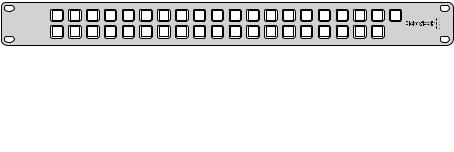
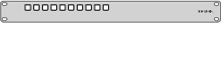
Videohub Smart Control is a 1 rack unit mountable control panel with 40 backlit pushbuttons and Ethernet connectivity, which works with all models of Videohub. It can be configured to work with one or many SDI destination devices. Once configured for your SDI equipment and Videohub router, Videohub Smart Control no longer requires a computer and can immediately change SDI routes as desired.
When configured for a single SDI destination, such as a monitor or deck, the pushbuttons can instantly switch between 40 different SDI sources on the same Videohub router. When configured for multiple SDI destinations, destination buttons become gold, source buttons become white and the lower right button can be configured as a take button and illuminates red. Macro buttons illuminate green when enabled and each one can be configured to perform up to 16 simultaneous crosspoint switches.
Videohub Smart Control
GPI and Tally Interface
GPI and Tally Interface is a low cost alternative for multi-camera productions where a Camera Control Unit (CCU) operator needs to switch video from one of several cameras being controlled to a single monitor. It features 8 configurable GPIs and 8 configurable GPOs.
Videohub Hardware Control Panels 12
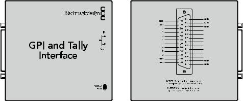
The GPIs send commands to your Videohub by ethernet to switch the selected camera to the operator’s monitor under certain crosspoint conditions. The GPOs send a tally signal to your cameras or other devices under certain crosspoint conditions.
GPI OUT
GPI IN 1
GPI OUT
GPI IN 2
GPI OUT
GPI IN 3
GPI OUT
GPI IN 4
GPI OUT
GPI IN 5
GPI OUT
GPI IN 6
GPI OUT
GPI IN 7
GPI OUT
GPI IN 8
GPI and Tally Interface |
Pinout diagram of the DB25 connector |
Refer to the pinout diagram on the back of the unit when fabricating your custom cable.
For information on how to configure your GPI and Tally Interface using Blackmagic Videohub Setup, refer to the ‘Blackmagic Videohub Software’ section of this manual.
Connecting USB to Configure the Control Panel
A USB 2.0 connection to a computer is used to configure the network settings of the Videohub Controller.
Be aware that the USB port of the Videohub Smart Control is inaccessible once it is installed in a rack. If you are likely to reconfigure Videohub Smart Control network settings periodically, then it may be convenient to permanently connect a USB cable to the unit before installing Videohub Smart Control in a rack.
Plugging into an Ethernet Network
In most facilities, Videohub is usually shared via an Ethernet network switch so it can be controlled by computers on the network as well as by Videohub control panels.
Videohub Master Control and Videohub Smart Control
Videohub Master Control and Videohub Smart Control connect to any Videohub via standard Ethernet networking and can be powered over Ethernet or with an external power supply.
If your Ethernet switch does not provide power over Ethernet, use the included universal power supply.
To connect a Videohub control panel to the local area IP based network:
1Connect the included power supply to your Videohub control panel. You can skip this step if your network switch provides power over Ethernet. No problem will be caused by connecting the power supply and power over Ethernet at the same time.
2Use the network In port on your Videohub control panel to connect to your network switch with a standard RJ45 Ethernet cable.
Videohub Hardware Control Panels 13
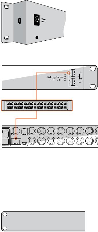
3You might also wish to connect another network device to the network Out port on your Videohub control panel, such as a Videohub router, another Videohub control panel or other network devices such as a computer or VoIP phone. The Out port does not provide power over Ethernet and any network device connected to this port will require its own power supply.
Side view of Videohub Smart Control showing the mini-B type USB port.
|
|
1 |
3 |
5 |
7 |
9 |
11 |
13 |
15 |
|
REF IN |
RS-422 |
2 |
4 |
6 |
8 |
10 |
12 |
14 |
16 |
|
CNTRL |
||||||||||
|
||||||||||
ETHERNET |
USB 2.0 |
|
|
|
|
|
SD/HD/3G/6G-SDI IN |
|
|
|
|
|
|
|
|
|
|
|
|
Videohub Smart Control connected to a Smart Videohub 20x20 via an Ethernet Network Switch.
Control Panel Button Diagnostics
When power is first connected to a Videohub control panel, all the buttons will display their test lights in the following sequence: red, green, blue and white. The top left button of a Videohub control panel indicates its network status, using the following diagnostic display:
Pink flashing light - unit is attempting to acquire an IP address. The button should quickly become red if the unit is set to use a static IP address, or if the unit successfully acquires an IP address from the DHCP server.
Videohub control panel is attempting to acquire an IP address.
Videohub Hardware Control Panels 14
Red flashing light - unit has acquired an IP address and is attempting to connect to the Videohub Server. Make sure the Videohub or Videohub Server computer is powered on and connected via Ethernet.
IP address has been acquired and control panel is attempting to connect to the Videohub Server.
Yellow flashing light - unit has connected to a Videohub Server computer but the Videohub Server is running an incompatible software or firmware version. Update Videohub with the latest version of the Videohub software and firmware and then power cycle the Videohub control panel.
Videohub Server is running an incompatible software or firmware version.
No flashing light - unit has successfully connected to the Videohub Server and is ready to control the Videohub if solid white, or solid white and gold, lights can be seen.
Control panel has successfully connected to the Videohub Server.
If the top left button took several minutes to turn red, the unit has failed to acquire an IP address and has eventually provided itself with a self-assigned AutoIP address in the 169.254.xxx.xxx format. Unless you wish to use an AutoIP address, disconnect and firmly reconnect the network cables to ensure they are properly connected, check for faulty network cables and make sure the DHCP server has spare IP addresses available. Unplug and reconnect all power sources from the Videohub control panel so it will request a new IP address from the DHCP server. The button should quickly become red. The unit will only perform these diagnostics when it is not selected in Videohub Hardware Panel Setup software.
Updating the Software in your Videohub Controller
Follow these steps to check if your Videohub control panel’s internal software is up to date:
1Connect your Videohub control panel to the computer via USB 2.0.
2Launch the Blackmagic Videohub Hardware Panel Setup.
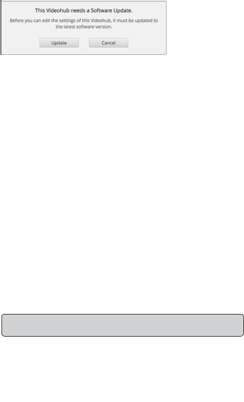
3If a software update is required, the following message will appear: “Software Update Required. The software on this Videohub Control is out of date. Would you like to update it now?” Click Yes. The update will take about 2 minutes to complete.
4The message “Software Update Complete” should appear at completion of the update. Click OK to dismiss the message. Settings can be changed now if desired and this is a good opportunity to give each Videohub control panel a unique name.
Videohub Hardware Control Panels 15
5 You can now unplug the USB cable from your Videohub control panel.
This message will appear if a internal software update is required.
About Routing Levels
If your Videohub does not feature RS-422 remote deck control, Videohub Master Control will always show “SDI” on its LCD and you don’t need to read anything more about routing levels.
If your Videohub does include RS-422 remote deck control ports, you can use the LEVEL button on Videohub Master Control to reduce the list of sources and destinations by routing level.
Start by pressing the DEST button. Now press the LEVEL button to cycle through the routing levels:
SDI 422
Choose this routing level to reduce the list of video equipment to devices with matching labels for their remote and SDI ports. This level is commonly used with SDI capture cards and VTR decks but cannot be used with cameras and monitors as they do not have RS-422 remote ports.
SDI
Lists all SDI sources and destinations. Choose this routing level if you want to see all SDI video equipment, i.e., cameras, monitors, capture cards and VTR decks, regardless of RS-422 connections.
422
Choose this routing level if you want to reduce the list of video equipment to all devices with RS-422 deck control. This will list sources and destinations by the names of their RS-422 remote ports, regardless of whether there are any associated SDI ports and regardless of whether any associated SDI ports have matching labels or not. This level is commonly used with SDI capture cards and VTR decks but also lists remote control panels and servers used to control decks.
|
|
|
|
|
|
|
|
|
|
|
|
Source |
SDI 422 |
|
|
|
|
|
|
|
|
|
|
SRC |
CLEAR |
VTR 10 |
|
|
|
|
|
|
|
|
|
|
|
|
|
Destination |
0 |
1 |
2 |
3 |
4 |
5 |
6 |
7 |
8 |
9 |
0 |
LEVEL DEST |
TAKE |
Monitor 2 |
|
Front panel showing a new source has been selected.
Source |
SDI 422 |
Source |
SDI |
EDIT 1 |
|
EDIT 1 |
|
Destination |
|
Destination |
|
VTR 1 |
|
VTR 1 |
|
Choose the SDI 422 routing level if you only want to see SDI video equipment with RS-422 deck control. In this example, the capture card (Edit 1) and the deck (VTR 1) are listed because they both have SDI and RS-422 ports.
Choose the SDI routing level if you want to see all SDI video equipment. In this example, the capture card (Edit 1) and the deck (VTR 1) are listed because they both have SDI ports.
Videohub Hardware Control Panels 16
Source |
422 |
serial 1
Destination
VTR 1
Choose the 422 routing level if you want to see all equipment with RS-422 remote deck control, including equipment with mismatched labels and also remote controllers. In this example, the
capture card (Edit 1) has a mismatched label for its remote port (serial 1) and is only listed when the routing level is set to 422.
How to Select Sources and Destinations
Videohub Master Control provides several ways to select and switch your destinations and sources quickly, depending upon whether you have customized the port labels on your Videohub router or if you just want to enter port numbers directly.
Videohub Master Control works in the same conceptual way as any other router control. These are the basic steps you will take, regardless of your method for selecting devices.
1Press the DEST button to display a destination on the LCD. Use the pushbuttons and/or the scroll wheel to find the desired destination.
2Press SRC and use the buttons and/or the scroll wheel to change the source connected to the destination.
3Press TAKE to confirm the route change.
How to select devices by typing the Videohub port numbers
If you’ve chosen to keep the default labels for all Videohub SDI and remote ports, you can simply type the port numbers to make a routing change. This method is fast but requires that you remember port numbers or have devised a system for knowing what equipment is connected to each Videohub port.
1Press the DEST button. The destination field will be highlighted blue on the LCD.
2If your Videohub router has RS-422 remote control, press the LEVEL button until you have set the appropriate routing level for your equipment. Otherwise you can skip this step.
3Type in the destination port number using the numeric pushbuttons. Each button will flash gold once as you press it. The destination will be displayed on the LCD. If you make a mistake, press the white CLEAR button and retype the port number.
4Press the SRC button. The source field will be highlighted blue on the LCD.
5Type in the source port number using the numeric pushbuttons. Each button will flash white once as you press it. The source will be displayed on the LCD. If you make a mistake, press the white CLEAR button and retype the port number.
6The TAKE button will flash red, awaiting your confirmation of the route change. Press TAKE and the route will change immediately. Otherwise, press CLEAR and no route change will take place. Videohub Master Control returns to its idle state with the latest route displayed on the LCD.
Videohub Hardware Control Panels 17
Source |
SDI |
Input 52
Destination
Output 88
If you’ve chosen to keep the default labels for all Videohub SDI and remote ports, you can simply type the port numbers to make a routing change. In this example, press DEST and then type the port number 88. Then press SRC and type the port number 52. Press TAKE to confirm the route change.
How to select devices with the scroll wheel
Regardless of whether or not you’ve customized the Videohub port labels, you can always use the scroll wheel to browse through a list of sources and destinations. This is the slowest method but is useful if you want to see the list of all available equipment and ports.
Press the DEST button. The destination field will be highlighted blue on the LCD.
1If your Videohub router has RS-422 remote control, press the LEVEL button until you have set the appropriate routing level for your equipment. Otherwise you can skip this step.
2Scroll the wheel forwards or backwards until the desired destination is found. The destination will be displayed on the LCD.
3Press the SRC button so it lights white. The source field will be highlighted blue on the LCD.
4Scroll the wheel until the desired source is found. The source will be displayed on the LCD.
5The TAKE button will flash red, awaiting your confirmation of the route change. Press TAKE and the route will change immediately. Or press CLEAR and no route change will take place. Videohub Master Control returns to its idle state with the latest route displayed on the LCD.
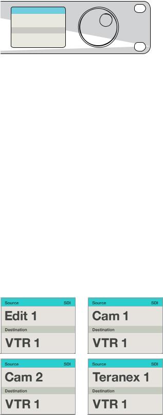
In this example, the scroll wheel is being used to list all sources that can be routed to the destination VTR 1, based upon the SDI routing level. When the scroll wheel is rotated, the names of source equipment are progressively displayed to make it very easy to find the desired video source.
Videohub Hardware Control Panels 18

How to select devices using the customizable buttons and scroll wheel
If you have customized the Videohub port labels, you can use the customizable buttons and scroll wheel together to find a short list of sources and destinations. This method is fast and intuitive because you only have to scroll through a short list of equipment and you don’t have to remember any port numbers. This method is very helpful if you label types of equipment together by name, e.g., VTR, Cam and Mon.
1Press the DEST button. The destination field will be highlighted blue on the LCD.
2If your Videohub router has RS-422 remote control, press the LEVEL button until you have set the appropriate routing level for your equipment. Otherwise you can skip this step.
3Press a button you have customized for a type of destination equipment, e.g., VTR. The button should light up gold.
4Scroll the wheel forwards or backwards until the desired destination is found. In this example, the destination VTR will be displayed on the LCD. If you make a mistake, press the white CLEAR button and scroll until the correct destination is displayed.
5Press the SRC button. The source field will be highlighted blue on the LCD.
6Press a button you have customized for a type of source equipment, e.g., a capture card.
The button should light up white.
7Scroll the wheel forwards or backwards until the desired source is found. In this example, the source capture card will be displayed on the LCD. If you make a mistake, press the white CLEAR button and scroll until the correct destination is displayed.
8The TAKE button will flash red, awaiting your confirmation of the route change. Press TAKE and the route will change immediately. Otherwise, press CLEAR and no route change will take place. Videohub Master Control will then return to its idle state with the latest route displayed on the LCD.
If any button you have customized for either a source or destination flashes but does not stay lit, Videohub Master Control is preventing you from selecting the button because the equipment type has not been labeled as a source or destination device or does not match the current routing level. For example, cameras should not usually be set as destination devices, monitors should not be set as source devices and won’t match the RS-422 routing level. Refer back to Creating Button Labels in Setting Up Videohub Master Control for steps on how to change this.
In this example, a customized Cam button has been selected so only cameras will be listed as sources, on the LCD, when the scroll wheel is rotated. This provides a fast way to find a video source because you only have to scroll through a short list of equipment.
Videohub Hardware Control Panels 19

How to select devices using the numeric buttons and scroll wheel
If you have customized the Videohub port labels with numbers, you can use the numeric buttons and scroll wheel together to find a short list of sources and destinations. This method is fast and intuitive because you only have to scroll through a short list of equipment and you don’t have to remember any port numbers. This method is very helpful if you label groups of equipment together by numbers, perhaps to represent locations. For example, all the equipment in Studio 3 could be labeled VTR3,
Edit 3, Cam 3A, Cam 3B, Mon 3A and Mon 3B etc.
1Press the DEST button. The destination field will be highlighted blue on the LCD.
2If your Videohub router has RS-422 remote control, press the LEVEL button until you have set the appropriate routing level for your equipment. Otherwise you can skip this step.
3Using the numeric pushbuttons, type the destination number, e.g., 3 for Studio 3. Each numeric button will flash gold as you press it.
4Scroll the wheel forwards or backwards until the desired destination is found. In this example, any of VTR 3, Edit 3, Mon 3A or Mon 3B could be displayed on the LCD.
If you make a mistake, press the white CLEAR button and scroll until the correct destination is displayed.
5Press the SRC button. The source field will be highlighted blue on the LCD.
6Using the numeric pushbuttons, type the source number, e.g., 3 for Studio 3. Each numeric button will flash white as you press it.
7Scroll the wheel forwards or backwards until the desired source is found. In this example, any of VTR 3, Edit 3, Cam 3A or Cam 3B could be displayed on the LCD. If you make a mistake, press the white CLEAR button and scroll until the correct destination is displayed.
8The TAKE button will flash red, awaiting your confirmation of the route change. Press TAKE and the route will change immediately. Otherwise, press CLEAR and no route change will take place. Videohub Master Control will then return to its idle state with the latest route displayed on the LCD.
In this example, the numeric button “3” has been selected so only video sources with a “3” in their label will be listed, on the LCD, when the scroll wheel is rotated. This provides a fast way to find a video source because you only have to scroll through a short list of equipment based upon a group number, e.g. only list the equipment in Studio 3.
How to select devices using the customizable and numeric buttons together
If you have customized the Videohub port labels with names and numbers, you can use the customizable buttons and numeric buttons together to directly select sources and destinations. This method is very fast and intuitive because you don’t have to scroll through a list of equipment and you only have to remember how many of each type of equipment you have, e.g., two VTRs and four monitors.
Videohub Hardware Control Panels 20
This method is very helpful if you label types of equipment by name and number, e.g., VTR 01, VTR 02, Cam 01, Cam 02, Cam 03, Mon 01, Mon 02, Mon 03 and Mon 04.
1Press the DEST button. The destination field will be highlighted blue on the LCD.
2If your Videohub router has RS-422 remote control, press the LEVEL button until you have set the appropriate routing level for your equipment. Otherwise you can skip this step.
3Press a button you have customized for a type of destination equipment, e.g., VTR. The button should light gold.
4Type in the destination equipment number using the numeric pushbuttons, e.g., 07 for VTR 07. Each numeric button will flash gold as you press it.
5Press the SRC button. The source field will be highlighted blue on the LCD.
6Press a button you have customized for a type of source equipment, e.g., a capture card. The button should light white.
7Type in the source equipment number using the numeric pushbuttons, e.g., 03 for the capture card Edit 03. Each numeric button will flash white as you press it.
8The TAKE button will flash red, awaiting your confirmation of the route change. Press TAKE and the route will change immediately. Otherwise, press CLEAR and no route change will take place. Videohub Master Control will then return to its idle state with the latest route displayed on the LCD.
If any button you have customized for either a source or destination flashes but does not stay lit, Videohub Master Control is preventing you from selecting the button because the equipment type has not been labeled as a source or destination device or does not match the current routing level. For example, cameras should not usually be set as destination devices, monitors should not be set as source devices and won’t match the RS-422 routing level. Refer back to Creating Button Labels in Setting Up Videohub Master Control for steps on how to change this.
Source |
SDI |
Edit 3
Destination
VTR 1
If you know that you want Edit 3 as the source, and VTR 1 as the destination, you can select the route directly without any
scrolling being necessary. In this example, press DEST, press the customized VTR button and then press 1. VTR 1 will be shown in the destination field. Now press SRC, press the customized Edit button and then press 3. “Edit 3” will be shown in the source field. Finally, press TAKE to confirm the route change.
Locking and Unlocking Routes
Videohub Master Control can lock and unlock any route on your Videohub. In contrast to Videohub Smart Control, Videohub Master Control can also unlock any destinations locked by other people using their computer, iPad or Videohub Smart Control.
Videohub Hardware Control Panels 21

To lock a destination using Videohub Master Control:
1Set the destination and source using whichever method you prefer. Once the route has been set, Videohub Master Control will return to its idle state.
2Press the DEST button. The destination field will be highlighted blue on the LCD.
3If the desired route is not already displayed on the LCD, use the pushbuttons and/or scroll wheel to find the destination to be locked.
4Press and hold the gold DEST button until a lock icon appears in the destination field of the LCD.
5Press DEST again to return Videohub Master Control to its idle state and the destination field will revert to gray.
Source |
SDI 422 |
Edit 1 |
|
Destination |
0 |
VTR 1 |
|
The destination field shows a lock icon if the destination is locked.
To unlock a destination using Videohub Master Control:
1Press the DEST button. The destination field will highlighted blue on the LCD.
2If the desired route is not already displayed on the LCD, use the pushbuttons and/or scroll wheel to find the destination to be unlocked. The destination field will show a lock icon for the locked destination.
3Press and hold the gold DEST button until the lock icon disappears from the destination field of the LCD.
4Press DEST again to return Videohub Master Control to its idle state and the destination field will revert to gray.
Source |
SDI 422 |
Edit 1
Destination
VTR 1
The lock icon disappears from the destination field when the destination is unlocked.
Using Videohub Smart Control as a Cut-Bus Controller
If Videohub Smart Control has been configured as a Cut-Bus controller, the destination device has already been chosen and you only need to choose a video source.
1Select a white video source button. The button will light up to distinguish it from the other sources. The video source will immediately connect and be viewable on the destination device.
Videohub Hardware Control Panels 22
2If the Take button has been enabled, the new source button and the Take button will flash. The route change will only take place when you confirm by pressing the Take button.
Videohub Smart Control configured as a Cut-Bus controller and with a Take button.
Using Videohub Smart Control as an XY Controller
If Videohub Smart Control has been configured as an XY controller, destination buttons light up gold and source buttons light up white. When working with multiple destinations, always select a destination button before selecting a source button.
To change routes:
1Select a gold destination button and it will light up brightly to distinguish itself from the other destination buttons. If a video source has previously been connected to this destination, its button will light up white.
2To connect a new source to the destination, press the desired video source button. The video source will immediately be connected and viewable on the destination device. The new source button will be brightly lit and the previous source button will dim to normal. To change another route, select another destination button and then select a new source button.
3If the Take button has been enabled, the new source button and the Take button will flash. The route change will only take place when you confirm by pressing the Take button.
Locking and Unlocking Routes
To lock a destination, press and hold the desired destination button until it turns blue. The corresponding source button will illuminate. If you attempt to change sources for a locked destination, the destination button will flash blue. To unlock a destination, press and hold the button until it returns to the standard gold color.
Using Macros
If you press a green macro button, it will simultaneously make the crosspoint changes you have previously configured in Videohub Hardware Panel Setup. Each button can be configured with up to 16 crosspoint routes. If you have the Take button enabled, the simultaneous change of routes will only take place when you confirm by pressing the Take button. If for any reason the macro cannot be performed, the button will flash.
Videohub Hardware Control Panels 23
Videohub Smart Control configured as an XY controller and with a Take button.
Labeling Pushbuttons
Videohub Master Control and Videohub Smart Control have removable face plates, which provide access to the pushbuttons for labeling.
Included with the software installer is a Videohub Control Labels folder containing both PDF and Adobe Illustrator template files. You can print and use either of these files for labeling the buttons. The Illustrator file contains text boxes so you can add your text labels before printing them out. If you don’t have Adobe Illustrator, you can just fill out and print the PDF file labels. Then cut out the square labels so they are ready to be inserted into the buttons.
To remove the face plate:
1Power off the unit, disconnect all cables and lay it flat with the buttons facing upwards.
2Using a No. 2 Phillips head screwdriver, remove the 8 screws found on the top and bottom sides of the faceplate.
3Gently lift the face plate off the unit. If you have a Videohub Master Control, take care not to pull on the data cable that connects the scroll wheel to the rest of the unit.
4The button caps can be easily lifted off with your fingers. Remove the clear cap from a button that you wish to label, while taking care to avoid lifting the silicon button membrane.
5Loosely place the printed label into the upturned clear cap.
6Use a pointy device, such as the tip of a screwdriver, to lightly press the four corners of the square paper label into the four rounded corners of the clear cap.
7Reinstate the clear cap containing the printed label. As the clear cap is pressed down onto its silicon button, the paper label will be pushed forward, and neatly held flat against the window of the clear cap. Repeat for as many buttons as you wish to label.
8Lower the face plate back into position, making sure the Blackmagic Design logo is the correct way up. If you have a Videohub Master Control, make sure the data cable tucks neatly into place.
9Reinstate the eight screws.
Congratulations! Your Videohub control unit is now ready to use!
Videohub Hardware Control Panels 24
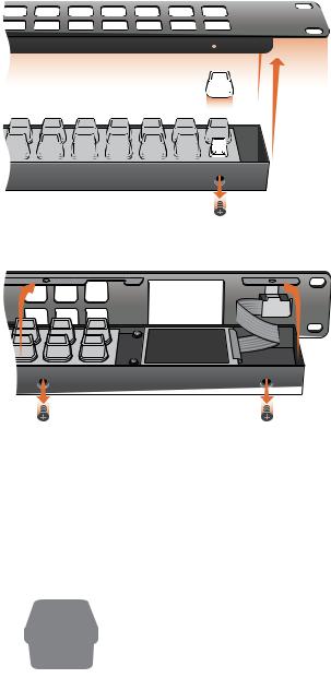
For Videohub Smart Control and Smart Videohub, remove the 8 screws, lift off the face plate and then the button caps.
For Videohub Master Control, remove the 8 screws, lift off the face plate and carefully allow the face plate to lie down next to the rest of the unit. Then remove the button caps.
Lightly press the four corners of the square label into the rounded corners of the clear cap.
Universal Videohub Routers
Universal Videohub 288
What you need to get started
Universal Videohub 288 is a large, modular router ideally suited to very large facilities and broadcasters. It features a 72 card rack frame that can be filled with any combination of BNC SDI or optical fiber SDI interface cards.
Universal Videohub Routers 25
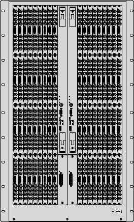
When fully populated with two Universal Videohub 288 Crosspoint cards, two power cards, 72 interface cards and 72 deck control cables, Universal Videohub 288 provides
288 SDI inputs, 288 SDI outputs, 288 bidirectional RS-422 deck control ports, reference input, redundant crosspoint processor, redundant Ethernet networking, redundant power and powerful Videohub routing control software for Mac OS X and Windows.
Occasionally, the internal software of the Universal Videohub 288 will need to be updated. Videohub Setup will prompt you if an update is required. The utility uses the USB 2.0 connection and you will need to provide a USB 2.0 type A to mini B male cable.
Universal Videohub 288 ships as an empty rack frame, except for a removable fan tray and fans. All other hardware components, such as SDI interface cards and power supplies, must be purchased and installed separately. Read the following section to help you decide which components you will need before you build your Universal Videohub 288.
Pages 40-41 provide information on the different interface cards available for your Universal Videohub.
MAIN POWER |
MAIN POWER |
+12V 800W |
+12V 800W |
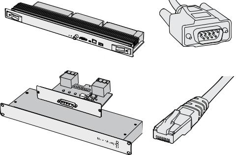
Universal Videohub 288 Crosspoint Card
This module contains the crosspoint processor for switching video routes and changing deck control ports. Ethernet, USB and serial ports are located on the card for router control.
A Reference input is located on the card for connection to a tri-level sync or black burst genlock signal.
An Alarm light will illuminate on the card if user intervention is required, e.g., if inadequate cooling has caused Videohub to overheat. Alarm notification is supplied by the GPI (General Purpose Interface) output to other devices.
Universal Videohub Routers 26
A Power Overload light will illuminate on the card if inadequate power is being supplied to the unit for the number of cards installed.
You will need a number 01 size Pozidriv screwdriver to install the Universal Videohub 288 Crosspoint card.
Router Control Cable
Remote router control is performed via 10/100Base-T Ethernet or serial. If router control is performed via Ethernet, the integrated Videohub Server is used. This means you only need to provide an Ethernet cable to connect Universal Videohub 288 to your Ethernet network switch.
Third party router controllers can control Universal Videohub 288 via Ethernet, or as an RS-422 slave device, for router crosspoint switching. Please refer to the Developer Information section of this manual for Videohub and RS-422 protocols.
Power Supply
When fully populated and running at maximum power consumption, Universal Videohub 288 can be powered by a single Universal Videohub Power Supply.
The Universal Videohub Power Supply package includes a power card with a single connection to a
1 RU size rack mount chassis which contains the power supply.
The Universal Videohub Power Supply chassis contains a universal power supply for use in all countries. You will need to provide a standard IEC cord with a C13 connector.
Universal Videohub 288 Crosspoint card |
Serial Cable |
POWER
MAIN
|
Videohub |
Power |
Supply |
Universal |
|
||
|
|
|
Universal Videohub Power Supply includes a power |
Standard RJ45 Ethernet Cable |
card, 1 RU chassis and connecting power cable. |
|
Building Universal Videohub 288
25 rack units of space should be reserved for the installation of Universal Videohub 288 and two rack mount power supply chassis, allowing free space for heat dissipation. Only 23 RU is required if Universal Videohub 288 is mounted at the top of an open rack as heat can be dissipated from the top.
Universal Videohub Routers 27
 Loading...